1
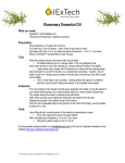
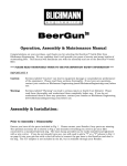
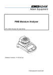
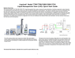
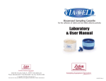
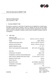
The Macro to Micro Interface ® InnovaPrep® Hydrosol Concentrator – Integrated Platform Operator’s Manual Table of Contents CHAPTER 1 Product Overview ................................................................................................................. 1 1.1 Product Description......................................................................................................................... 1 1.2 Applications ..................................................................................................................................... 1 1.3 How the InnovaPrep Hydrosol Concentrator Operates ................................................................... 1 1.4 InnovaPrep History .......................................................................................................................... 1 CHAPTER 2 Description of the InnovaPrep Concentrator ........................................................................ 1 2.1 Front Panel ...................................................................................................................................... 1 2.2 Internal Components ...................................................................................................................... 3 CHAPTER 3 Installation ............................................................................................................................ 5 3.1 Materials Provided .......................................................................................................................... 5 3.2 Materials Required But Not Provided ............................................................................................. 5 3.3 Installing a Concentration Cell ......................................................................................................... 5 3.4 Uninstalling a Concentration Cell .................................................................................................... 6 3.5 Filling the Extraction Fluid Reservoir ............................................................................................... 6 3.6 Draining the Extraction Fluid Reservoir ........................................................................................... 7 3.7 Installing the CO2 Cylinder ............................................................................................................... 7 3.8 Removing the CO2 Cylinder ............................................................................................................. 7 3.9 Cleaning the Extraction Fluid Reservoir ........................................................................................... 7 3.10 Calibration of the Optical Sensors ................................................................................................. 8 CHAPTER 4 Concentrator Operation ....................................................................................................... 9 4.1 LCD Control Panel ............................................................................................................................ 9 4.2 Setting the Extraction Fluid Volume ................................................................................................ 9 4.3 Concentrating a Liquid Sample ...................................................................................................... 10 4.4 Additional Sample Extractions....................................................................................................... 10 4.5 Concentration Cell Decontamination ............................................................................................ 10 4.6 Concentration Cell Storage............................................................................................................ 11 4.7 Cell Selection ................................................................................................................................. 11 CHAPTER 5 Troubleshooting.................................................................................................................. 16 Revision 05/23/11 www.innovaprep.com i CHAPTER 1 Product Overview This chapter contains a product description of the InnovaPrep hydrosol concentrator and a brief description of instrument operation. 1.1 Product Description The hydrosol concentrator, shown in Figure 1-1, quickly and efficiently concentrates waterborne bacteria, viruses, DNA, toxins, protozoa, or other particles of interest from large liquid sample volumes into liquid volumes as small as 100 microliters (smaller volumes are achievable in some applications). The system uses a novel elution method to recover organisms that have been captured onto hollow fiber membrane filters into very small volumes. Figure 1-1. InnovaPrep Hydrosol Concentrator – Integrated Platform 1.2 Applications The InnovaPrep technology has application anywhere that analysis of low concentrations of particles is needed. The primary area of application is for preparing and concentrating bacteria, viruses, DNA, and other particles of biological origin, including pathogens, for subsequent analysis by microbiological methods or with microbiological detection devices. 1.3 How the InnovaPrep Hydrosol Concentrator Operates The InnovaPrep system uses a novel wet foam elution method to recover organisms that have been captured onto hollow fiber membrane filters into user settable volumes as small as 100 micro liters (smaller volumes are achievable in some applications). 1.4 InnovaPrep History The technology was developed by a team of veteran aerosol research scientists in response to the recognized need for a macro-to-micro interface between the large liquid sample volumes collected by many bioaerosol samplers and advanced detectors which require ultra low volumes. InnovaPrep was founded in 2008 to commercialize this new concentration and sample preparation technology developed by AlburtyLab, Inc. and Page Applied Research LLC. Revision 12/27/13 www.innovaprep.com 1 CHAPTER 2 Description of the InnovaPrep Concentrator The following chapter describes the components of the InnovaPrep Hydrosol Concentrator – Integrated Platform. 2.1 Front Panel The following section describes the main components of the front panel of the InnovaPrep hydrosol concentrator as is shown in Figure 2-1. Revision 12/27/13 www.innovaprep.com 1 Figure 2-1. InnovaPrep Hydrosol Concentrator - Integrated Platform Front Panel 2.1.1 LCD Control Panel Functions of the hydrosol concentrator are managed through a user interface LCD control panel located in the upper left hand corner of the front panel. Detailed instructions on the operation of the LCD control panel are provided in Section 4.1 . 2.1.2 Pumps Two liquid peristaltic pumps are located directly below the LCD control panel. The left serves as the feed pump and the right serves as the permeate pump. Each pump is controlled to maintain feed and permeate pressures set through the LCD control panel. 2.1.3 Extraction Fluid Reservoir Ports Three ports are located in the lower right hand corner of the front panel. Fill is used to fill the extraction fluid reservoir, Drain is used to drain the extraction fluid reservoir, and Vent is used both to vent gas from the extraction fluid reservoir, and to vent gas from the CO 2 cylinder. 2.1.4 Control Valves Two red-faced control valves are located below the peristaltic pumps. These control the flow of the extraction fluid and carbon dioxide. The desired position should be selected by slowly rotating the valve. Built-in positioning detents allow the valves to snap into place, ensuring correct positioning of the valves. The position settings for each of the control valves are described below. The Extraction fluid valve has four positions as follows: Revision 12/27/13 www.innovaprep.com 2 Fill Run Drain Off In this position, the extraction fluid reservoir is connected to the port labeled Fill. The reservoir can be filled through this port. Note: Vent reservoir pressure completely prior to switching valve to this position. In this position, the extraction fluid reservoir is connected to the foam valve and is ready for extraction. In this position, the fluid can be drained from the extraction fluid reservoir to the port labeled Drain. In this position, the extraction fluid reservoir is disconnected from the fill, drain, and run fluidics. The CO2 valve has four positions as follows: CO2 vent In this position, the CO2 supply lines are connected to the port labeled Vent. Note: Switching to CO2 vent with a CO2 cylinder fully engaged will vent the entire cylinder. Follow the instructions for removing the CO2 cylinder. Run In this position, the CO2 supply lines are connected and ready for operation. NOTE: it is only in this position that the Extraction fluid pressure gauge indicates the pressure on the extraction fluid reservoir, in all other positions it indicates the pressure being supplied to the valve by the regulator. Off In this position, the CO2 supply lines are valved off from the system including the extraction fluid reservoir. Reservoir vent- In this position, the CO2 head pressure is vented from the extraction fluid reservoir to the port labeled Vent. 2.1.5 Pressure Gauges Two pressure gauges located below the control knobs display the pressure in the CO2 cylinder (CO2 supply pressure) and in the extraction fluid reservoir (Extraction fluid pressure). Directly to the left of the extraction fluid pressure gauge is a PSI adjustment screw. Using a 7-mm nut driver the gas pressure in the extraction fluid reservoir can be easily adjusted. NOTE: When the pressure is increased, the operator should wait approximately 20 minutes prior to processing a sample. This allows for the CO2 to come into equilibrium with the extraction fluid. 2.1.6 Flow Rate Needle Valves Two adjustable flow rate needle valves are located at the top of the hollow fiber concentration cell. The left needle valve adjusts the extraction fluid flow rate and is identified as Ext. fluid flowrate. The right needle valve adjusts the CO2 flush flowrate. 2.1.7 Hollow Fiber Concentration Cell The concentration cell is positioned vertically just to the left of the carbon dioxide cylinder on the right hand side of the front panel. The concentration cell is connected to the system at ports A, B, and C; and to the retentate valve and a fluid sensor located directly above the retentate valve. 2.1.8 Retentate Valve The bottom retentate tube on the hollow fiber concentration cell runs through the retentate valve that is located directly below the concentration cell. This valve controls concentrate fluid flow from the concentration cell. Revision 12/27/13 www.innovaprep.com 3 2.1.9 Concentrate Reservoir (if present) Directly below the retentate valve is the concentrate reservoir (if present). This reservoir can be removed and the concentrate can be captured into a small sample tube or the reservoir can be connected with an outlet tube for integration into an automated system. 2.1.10 Liquid CO2 Cylinder A 12-gram liquid CO2 cylinder is required for carbonating the extraction fluid. The cylinder is installed into the black cylinder housing located on the far right side of the front panel. 2.1.11 Ports A, B, and C Port A is the feed port; the sample is pumped into the concentration cell through this port. Extraction fluid also enters the cell through this port. Port B is the permeate purge port and port C is the permeate port. The hollow fiber concentration cell should be positioned with the “up arrow” (if present) on the concentration cell label in the up position and the corresponding ports connected. 2.2 Internal Components The following sections describe the serviceable internal components of the InnovaPrep hydrosol concentrator as is shown in Figures 2-2 and 2-3. A certified InnovaPrep technician should service internal components not described here. Please contact InnovaPrep (816-619-3375) for assistance. 2.2.1 Power Power to the hydrosol concentrator is provided through a separate external 12-volt DC power supply. The power supply is connected to the 12VDC+ and 12VDC- connectors located on the back, right-hand corner of the bottom plate. 2.2.2 Communications Ports Communications ports are located on the same white connector block as the 12-volt input. The “IN” ports are operated by 12v to 24v positive logic, the “OUT” ports signal 12v high and 0v low. As of software version 1.1-M the ports operate as follows: IN1- Start Run, IN2- Extract, IN3- Not used, and OUT1- System busy. 2.2.3 Feed In Port A 1/4-28 flat bottom port labeled Feed In is located on the right hand side approximately half way up from the bottom, internal plate. A section of tubing with a 1/4-28 flat bottom connector should be attached to this port from an outside reservoir containing the feed sample. 2.2.4 Permeate Out Port A 1/4-28 flat bottom port labeled Permeate Out is located two ports to the left of the Feed In port on the right hand side approximately half way up from the bottom, internal plate. A section of tubing with a 1/4-28 flat bottom connector should be attached to this port and placed into an outside reservoir to catch the permeate fluid. Revision 12/27/13 www.innovaprep.com 4 Figure 2-2. InnovaPrep Hydrosol Concentrator - Integrated Platform Internal Components; Back View Figure 2-3. Revision 12/27/13 InnovaPrep Hydrosol Concentrator - Integrated Platform Internal Components; Top View www.innovaprep.com 5 CHAPTER 3 Installation Included in this chapter are the general instructions for the setup of the InnovaPrep Hydrosol Concentrator – Integrated Platform. Inspect each component when unpacking. If damage is observed, do not use the instrument, and contact your shipping representative immediately. Remove any protective packaging that may be present around the instrument. Examine the packaging material to be sure that materials that have been provided (see the list below) are removed. 3.1 Materials Provided Component InnovaPrep concentrator Programming Cable 7 mm Nut Driver Pre-filter Kit Tubing supply kit 12 g food grade C02 Cartridge Qty 1 1 1 1 1 2 3.2 Materials Required But Not Provided The reagent for sample extraction is required in order to use the system. The user must provide this. A standard 60 mL syringe equipped with a 0.2 µm filter is required for the transfer of fluids into the extraction fluid reservoir and for flushing the sample path. One Syringe filter kit is provided. Additional syringe filter kits (Part # HC05100) are available for purchase on the InnovaPrep website. Instructions for loading the extraction fluid reservoir are included in Section 3.5 . A 12-gram carbon dioxide cylinder is required for charging the extraction fluid reservoir; two are provided. These cartridges are available from the InnovaPrep website in 5-packs (Part #HC05051-5) or in 10-packs (Part #HC05051-10). Instructions for installing the CO2 cylinder are included in Section 3.7. A personal computer with a serial port is required for uploading new protocols to the hydrosol concentrator. Please contact InnovaPrep (816619-3375) for information regarding this feature. A 12-volt DC power supply is required to power the concentrator. 3.3 Installing a Concentration Cell To install a concentration cell, refer to Figure 3-1 and use the following procedure: 1. Hold the concentration cell with the arrow on the label pointing up and the permeate ports facing toward the instrument. Revision 12/27/13 www.innovaprep.com Figure 3-1. Concentration Cell Installation 6 2. Guide the bottom of the cell into the retentate port and twist clockwise to seal, the permeate ports should end up facing toward the right and away from the instrument as shown. 3. Attach the top port of the cell to port A on the instrument 4. Attach the upper permeate port on the concentration cell to port B on the instrument. 5. Attach the lower permeate port on the concentration cell to port C on the instrument. 3.4 Uninstalling a Concentration Cell To uninstall a concentration cell, refer to Figure 3-1 and use the following procedure: 1. Detach connectors A and B and place caps or plugs into the ports. 2. Detach connector C and place caps or plugs into the ports. 3. Detach the tubing from the bottom port of the concentration cell and replace with a cap or plug. *Note: The concentration cell must be filled with an appropriate storage fluid and capped prior to storing. InnovaPrep recommends a 0.01% sodium hydroxide solution. Contact InnovaPrep regarding questions about specific membrane types (816-619-3375). 3.5 Filling the Extraction Fluid Reservoir 1. If the extraction fluid pressure will remain the same it is not necessary to adjust the Extraction fluid pressure regulator prior to filling; however, if a lower pressure is desired begin by inserting a 7 mm nut driver into the opening for the extraction fluid pressure regulator and turning two or more counterclockwise turns to reduce the pressure to less than the desired pressure (if resistance is met stop turning). 2. Slowly set the CO2 valve to Reservoir vent. If there is still fluid in the reservoir, be prepared for foam to flow out of the vent port, it may be necessary to plumb a waste container to catch the foam as the CO2 off-gasses from the remaining extraction fluid. 3. After the gas has stopped venting, set the Extraction fluid valve to Fill. 4. Load a sterile syringe with no more than 50 mL of the desired extraction fluid, attach a 0.2µm filter to the syringe and attach the outlet of the filter it to the Fill port. 5. Fill the extraction fluid reservoir with no more than 50 mL of extraction fluid. Use the volume markings on the syringe to track the volume of extraction fluid loaded into the extraction fluid reservoir. 6. Switch the Extraction fluid valve to Run. 7. Switch the CO2 valve to Off. 8. Using the 7 mm nut driver, slowly turn the Extraction fluid pressure regulator adjustment screw clockwise until the desired pressure is reached. NOTE: it may take several turns before the regulator engages, but once it does engage the pressure can increase rapidly. 9. When you are ready to pressurize the extraction fluid, switch the CO2 valve to Run. NOTE: The operator should wait approximately 20 minutes prior to processing a sample. This allows for the CO2 to come into equilibrium with the extraction fluid. 10. Flush the foam line to remove all unpressurized fluid by performing a Foam Line Purge by following the menu path below: Run Settings Extract settings Revision 12/27/13 www.innovaprep.com 7 Foam line purge—The LED panel will instruct you to “Disconnect cell at port “A” hold a waste container under the tube” Start. Allow the fluid to purge until the foam is of the proper consistency Stop 3.6 Draining the Extraction Fluid Reservoir 1. Attach a length of tubing to the Drain port and place the other end in an appropriate waste container. 2. If there is no pressure on the extraction fluid, raise it to approximately 50 PSI. 3. Switch the CO2 valve to Off. 4. Slowly switch the Extraction fluid valve to Drain. Control the flow rate using the Extraction fluid valve. 5. When the extraction fluid has finished draining, switch the Extraction fluid valve to Off. 3.7 Installing the CO2 Cylinder 1. 2. 3. 4. Set the Extraction fluid valve to Run. Set the CO2 valve to Off. Place the CO2 cylinder into the bottom CO2 cylinder housing. Screw in the bottom housing until resistance is met; then rapidly screw the housing in until snug. 5. If the regulator is set to the correct pressure then proceed to step 6. If not, use the 7 mm nut driver and slowly turn the Extraction fluid pressure regulator adjustment screw clockwise until the desired pressure is reached. 6. When you are ready to pressurize the extraction fluid, switch the CO2 valve to Run. 3.8 Removing the CO2 Cylinder 1. If there is any pressure shown on the CO2 Supply Pressure gauge; slowly turn the CO2 valve to CO2 Vent to vent any remaining CO2 out of the cylinder. If no gas flows, the Extraction fluid pressure regulator may need to be turned up. 2. When gas has stopped flowing, set the CO2 valve to Off. 3. Remove the CO2 cylinder. 3.9 Cleaning the Extraction Fluid Reservoir The Extraction Fluid Reservoir may require sterilization after the HSC-40 has an extended period of non-use. 1. Remove the concentration cell from unit. 2. Drain Reservoir - Follow Section 3.5 “Draining the Extraction Fluid Reservoir” to remove any remaining extraction fluid. 3. Clean with 0.1 % N Sodium Hydroxide. a. Slowly set the CO2 valve to Reservoir vent. b. Wait for the venting gas to stop, and then set the Extraction fluid valve to Fill. c. Load a syringe with 0.1 % sodium hydroxide and, using a section of tubing, attach it to the Fill port on the lower right hand side on the front face of the unit. d. Attach a section of tubing to the Vent port on the lower right hand side of the front face of the unit and place the opposite end into a waste container. e. Fill the extraction fluid reservoir with approximately 75 mL of extraction fluid – until fluid begins to flow out of the Vent port. Revision 12/27/13 www.innovaprep.com 8 f. Let the 0.1 % sodium hydroxide remain in the extraction fluid reservoir for 20 minutes. g. Follow Section 3.5 “Draining the Extraction Fluid Reservoir” to remove the sodium hydroxide. 4. Rinse the unit twice with sterile filtered laboratory water a. Slowly set the CO2 valve to Reservoir vent. b. Wait for the venting gas to stop, and then set the Extraction fluid valve to Fill. c. Load a filter equipped syringe with sterile laboratory grade water and, using a section of tubing, attach it to the Fill port on the lower right hand side on the front face of the unit. d. Attach a section of tubing to the Vent port on the lower right hand side of the front face of the unit and place the opposite end into a waste container. e. Fill the extraction fluid reservoir with approximately 75 mL of water – until fluid begins to flow out of the Vent port. f. Follow Section 3.5 “Draining the Extraction Fluid Reservoir” to remove the sterile filtered laboratory grade water. 3.10 Calibration of the Optical Sensors Warning: Before calibrating the optical sensors in the hydrosol concentrator the fluid lines must be clean and dry. Any residual liquid or bubbles in the tubing could interfere with accurate calibration of the optical sensors. The following procedure should be used to calibrate the optical sensors: Press “Settings” on the home screen. Select “System settings”. Select “Fluid sensor cal.”. Press “Calibrate”. After the calibration is complete a pass/fail page will appear with two light bulbs, which corresponds, to the two optical sensors. An illuminated light bulb indicates an optical sensor did not calibrate correctly. If so, make sure there is no fluid in the lines; then repeat the above procedure. Revision 12/27/13 www.innovaprep.com 9 CHAPTER 4 Concentrator Operation Included in this chapter are the general instructions for operation of the InnovaPrep Hydrosol Concentrator – Integrated Platform. 4.1 LCD Control Panel Control of the InnovaPrep CONCENTRATOR is performed using the LCD control panel, as shown in Figure 4-1. Figure 4-1. InnovaPrep CONCENTRATOR LCD Control Panel 4.2 Setting the Extraction Fluid Volume 1. Set the extraction fluid pressure to desired level using a 7 mm nut driver (inserted in the port to the left of the Extraction Fluid Pressure gauge) turn slowly until desired pressure is reached. 2. Wait a minimum of 20 minutes for the CO2 to dissolve into the extraction fluid. 3. Perform a Foam Line Purge by following the menu path below: Run Settings Extract settings Foam line purge—The LED panel will instruct you to “Disconnect cell at port “A” hold a waste container under the tube” Start. Allow the fluid to purge until the foam is the proper consistency Stop 4. Set the “Foam timer” value in seconds in the "Extract settings" menu. Revision 12/27/13 www.innovaprep.com 10 5. 6. 7. 8. Settings Extract settings Foam timer – set to 0.100s Disconnect the cell at port “A” and hold a tare-weighed vile under the tube coming out of port A Perform a test extract from the extraction settings menu Weigh the vial, the volume of extraction fluid should be approximately 100 µL, adjust the foam flow rate valve up or down as necessary so that a 100 millisecond extraction produces approximately 100 µL of extraction fluid. From this point adjust for your desired sample volume using the Foam Timer setting. 4.3 Concentrating a Liquid Sample 1. Connect a section of tubing from an appropriate reservoir to the Feed In port located on the right hand side of the inside of the instrument. 2. Connect a section of tubing from the Perm out port (located inside the instrument) to a waste container. 3. Place a feed sample into the reservoir. 4. Place an appropriate sample collection container under the retentate tube on the bottom of the concentration cell or attach the concentrate reservoir and a section of tubing. 5. Press Start on the main menu of the LCD Control Panel. 6. Sample will be automatically processed and the concentrate will be dispensed into the sample concentrate tube or concentrate reservoir. 4.4 Additional Sample Extractions Additional extractions of the concentration cell can be performed by pressing “2” on the control panel to emulate a signal from the communication port “IN2”. 4.5 Concentration Cell Decontamination Decontamination of the concentration cell may be necessary in some instances. Decontamination can be performed with any of the methods described below. Perform one or more additional extractions of the concentration cell to remove remaining material from the concentration cell. Place clean feed fluid, filtered laboratory grade water, or surfactant solution into the feed reservoir and run as a sample. Follow with additional extractions as necessary. 4.5.1 Decontamination Fluid - Options It is important to check the chemical compatibility of each concentration cell media type before choosing your decontamination fluid. 0.01% N sodium hydroxide - run as a sample. Follow with multiple rinses of sterile filtered laboratory grade water. 200 ppm sodium hypochlorite - run as a sample. Follow with 200 ppm sodium thiosulfate to deactivate the sodium hypochlorite. Follow with sterile filtered laboratory grade water. Use chlorine test strips to ensure that the sodium hypochlorite solution has been completely removed. Revision 12/27/13 www.innovaprep.com 11 3% hydrogen peroxide - run as a sample. Follow with multiple rinses of sterile filtered laboratory grade water. Use hydrogen peroxide test strips to ensure that the hydrogen peroxide solution has been completely removed. 4.5.2 Autoclaving of Concentration Cells The following steam autoclaving method is recommended for use with hollow fiber modules: 1. Remove and discard all plastic packaging, as these should not be autoclaved; wet the membrane (optional). 2. Loosen all sanitary connections, Luer™ fittings, clamps and flange nuts to avoid damaging the module during the autoclave cycle. 3. Wrap all open ports of the connecting tubing with autoclave paper. 4. Pre-warm the module to 102°C at 10 psi for 10 minutes. 5. Ramp up the autoclave by increasing pressure approximately 1.5 psi/min for 30 minutes to 123°C. 6. Hold the autoclave at 123ºC for 50 minutes. Do not exceed 124ºC. 7. Slowly ramp down the temperature of the autoclave by exhaust pressure release of approximately 0.75 to 1.0 psi/min to 104°C. 8. Hold the autoclave at 104°C for at least 20 minutes. 9. Bring the module to room temperature. 10. Tighten all sanitary connections, Luer™ fittings or any other clamps or connections if they are fitted in the module. 4.6 Concentration Cell Storage Concentration cells are generally stored in 0.01% N sodium hydroxide. The cells should be rinsed with sterile filtered water prior to use. Please contact InnovaPrep (816-619-3375) for assistance in selection of other storage fluids or with dry storage. 4.7 Cell Selection Table 4-1 contains a chemical resistance chart for the various components of the HCI-40 system. This chemical resistance chart is intended for use as a guide, not as a guarantee of chemical compatibility. Variations in temperature, concentrations, durations of exposure, and other factors may affect the use of the product. It is recommended that testing be performed under the user’s specific conditions. Revision 12/27/13 www.innovaprep.com 12 Revision 12/27/13 Cellulose Ester (CE) / Mixed Cellulose Ester (ME) Regenerated Cellulose (RC) Polysulfone (PS) / Polyethersulfone (PES) Polypropylene (PP) Polyvinylidene difluoride (PVDF) Nylon (N) Stainless Steel (SS) Polyester (P) Fluorocarbon (F) R=Recommended L= Limited Exposure NR=Not Recommended U=Unknown 5% Acetic acid 25% Acetic acid Acetic acid (glacial) Acetone Acetonitrile Dilute Ammonium hydroxide Conc. Ammonium hydroxide Amyl acetate Amyl alcohol Aniline Benzene Benzyl alcohol Boric acid Brine Bromoform Butyl acetate Butyl alcohol Butyl cellosolve Butylaldehyde Carbon tetrachloride Cellosolve Chloroacetic acid Chloroform Chromic acid Cresol Cyclohexane Cyclohexanone Diacetone alcohol Dimethyl formamide Dimethylsulfoxide 1,4 Dioxane Ethers Ethyl acetate HCI-40 Sample Fluidics Table 4-1. Chemical Resistance Chart L NR NR NR NR U R NR NR U NR NR R U U NR NR U U NR U NR NR L NR NR NR NR U U U NR U L NR NR NR NR NR NR NR L NR NR NR R R NR NR L NR NR NR NR NR L NR NR L NR NR NR NR NR NR NR R R R R R R L R R R R R R R R R R L R R L R R NR R R R R L R L R R R R R NR NR R R NR L NR L NR R R NR NR R NR NR NR R NR L NR NR L NR NR NR NR L NR NR R R R R R R R R R R R R R R R R R U R R R R R L R R R R R R R L R R R R L L R R R R R R L R R R R R R R R R R R R NR R L R NR L R L R NR NR L R U R R L R R R U L R U R L U U NR U NR R NR NR R R R R U U R R L L L R U R R R R R L L L R U L R U U L U L R L R R R L R U U R L L NR NR R U U U L R U R NR R R U R R U U R U U R U U U R U NR U R NR U R R R R U R R R R R R R R R U R U U R U R R R U R R R R U U R R R www.innovaprep.com 13 Revision 12/27/13 HCI-40 Sample Fluidics Cellulose Ester (CE) / Mixed Cellulose Ester (ME) Regenerated Cellulose (RC) Polysulfone (PS) / Polyethersulfone (PES) Polypropylene (PP) Polyvinylidene difluoride (PVDF) Nylon (N) Stainless Steel (SS) Polyester (P) Fluorocarbon (F) R=Recommended L= Limited Exposure NR=Not Recommended U=Unknown Ethyl Alcohol 15% Ethyl alcohol 95% Ethyl alcohol Ethylene dichloride Ethylene glycol Ethylene oxide 2% Formaldehyde 30% Formaldehyde 25% Formic acid 50% Formic Acid Freon® Gasoline Glycerine Glycerol Hexane Hexanol 5% Hydrochloric acid 25% Hydrochloric acid 37% Hydrochloric acid 25% Hydrofluoric acid 30% Hydrogen peroxide Iodine solutions Isobutyl alcohol Isopropanol Isopropyl acetate Isopropyl alcohol Isopropyl ether Jet Fuel 640A Kerosene Lactic acid Methyl acetate Methyl alcohol 98% Methyl alcohol Methyl cellosolve Methyl chloride U U U NR NR NR L L L L NR NR NR U NR U NR NR NR NR R U U U NR NR NR NR NR R NR L L NR NR L R L NR L NR L L NR NR R R R R R L R NR NR NR R NR R L NR L L R R R NR L L L NR R R R R R L R R R R R R R R R R R NR NR L R NR R R R R R R R R R R R L R R R L NR R R R R R R R L R R R R R R R L R NR R R NR R R R R R NR L R R NR R R R L R R R R R R R R R R R R R R L NR R R R R R R L R R R R R R R R R R R R R R R R R R R R R R R R R R R R R R R R R R R R R R R R R R L R R R R R R R R NR NR NR R R R L R L NR NR L NR L NR NR L NR R L R L R L L L L R R R L L L R R L L R R R R R R NR NR NR NR L NR R L L L R R R L R R R L R R R R U R U R R NR NR R R R R R R R R R NR R U U R R R U U L R L U U U U R R R R R R R R R R R R R R R R R R R R R R R R R R R R R R R R R R R www.innovaprep.com 14 Revision 12/27/13 Polysulfone (PS) / Polyethersulfone (PES) Polypropylene (PP) Polyvinylidene difluoride (PVDF) Nylon (N) Stainless Steel (SS) Polyester (P) Fluorocarbon (F) U Regenerated Cellulose (RC) NR U NR U NR U L NR NR NR NR NR U R NR NR NR NR NR NR NR NR U U U U NR R R R R U U Cellulose Ester (CE) / Mixed Cellulose Ester (ME) HCI-40 Sample Fluidics R=Recommended L= Limited Exposure NR=Not Recommended U=Unknown Methyl ethyl ketone Methyl formate Methylene chloride N-methyl-2-pyrrolidone Mineral spirits Monochlorobenzene 5% Nitric acid 25% Nitric acid 6 N Nitric acid 70% Nitric acid Conc. Nitric acid Nitrobenzene Nitropropane Oils, mineral Pentane 25% Perchloric acid Perchloroethylene Petroleum based oils Petroleum ether 0.5% Phenol 10% Phenol 25% Phosphoric acid 1 N Potassium hydroxide 25% Potassium hydroxide 50% Potassium hydroxide Propanol Pyridine Silicone oil 0.1 N Sodium hydroxide 5% Sodium hydroxide 25% Sodium hydroxide 50% Sodium hydroxide Conc. Sodium Hydroxide Sodium hypochlorite 5% Sulfuric acid NR NR L NR R L L NR NR NR NR NR NR R R NR NR R R R NR NR L NR NR R NR R L NR NR NR NR R L R L R R R R R NR NR NR NR L L R R L R R R R R L L R NR R R R R L L NR NR R R NR NR L NR R NR R R R NR R NR NR R R NR NR R R R L R NR R R R NR R R R R R R R R R R R R R L R R L NR NR NR L R R NR L R R R R R R R R R R R R R R R R L R L R R R R R NR NR R NR L R R R R R R R R R R R R R R R L R R R R R R R R R U L U R U NR NR NR NR NR L U R R NR L R U NR NR L L L L NR L R R R R R L NR L R U L L R U R R R R R L U R L L L R U L L NR L L L R R R L L L L L NR NR U U NR U U U R L R NR NR NR U U R U U R R L NR U R R L R NR U R L NR NR NR U NR R U R U R U R R R R R R U R R R R R U R R R R R R R R R R R R R R R R www.innovaprep.com 15 Revision 12/27/13 HCI-40 Sample Fluidics Cellulose Ester (CE) / Mixed Cellulose Ester (ME) Regenerated Cellulose (RC) Polysulfone (PS) / Polyethersulfone (PES) Polypropylene (PP) Polyvinylidene difluoride (PVDF) Nylon (N) Stainless Steel (SS) Polyester (P) Fluorocarbon (F) R=Recommended L= Limited Exposure NR=Not Recommended U=Unknown 25% Sulfuric acid 6 N Sulfuric acid Conc. Sulfuric Acid Tetrahydrofuran Toluene 25% Trichloroacetic acid Trichlorobenzene Trichloroethane Trichloroethylene Triethylamine Turpentine Urea 6 N Urea Water Xylene NR NR NR NR NR NR U NR NR U NR U U R NR NR NR NR NR R NR NR L R NR NR R NR R NR L L NR R R NR R R R R R R R R R R R R NR L R NR L R NR NR R NR R NR R R NR R R R R R R L R R R R R R R L R R R R R NR R R R R R R NR NR NR R R L U L L R L R R R R NR NR NR R R NR U L L R R L L R L NR NR NR R U NR U L R U U R R R NR R R R R R R U R R R R R R R R www.innovaprep.com 16 CHAPTER 5 Troubleshooting Please contact InnovaPrep for technical assistance and troubleshooting. InnovaPrep LLC 132 E. Main St. Drexel, MO 64742 Phone: 816-619-3375 [email protected] www.innovaprep.com Revision 12/27/13 www.innovaprep.com 17