1
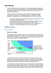
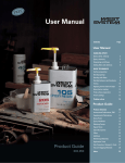
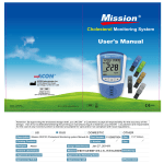
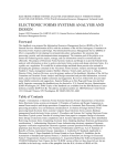
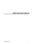
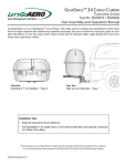
ACD-‐200 Bobcat Dry Filter Air Sampler User’s Guide Copyright 2012, InnovaPrep LLC www.innovaprep.com 1 Table of Contents 1 Product Overview .................................................................................................................................... 3 1.1 Product Description ......................................................................................................................................... 3 1.2 Applications ..................................................................................................................................................... 3 1.3 Materials Provided .......................................................................................................................................... 3 1.4 Materials Required But Not Provided .............................................................................................................. 4 2 ACD-‐200 Bobcat Method of Operation ..................................................................................................... 4 2.1 Sample Collection on an Electret Filter ............................................................................................................. 4 2.2 Wet Foam Elution ............................................................................................................................................ 4 2.3 Foam Generation ............................................................................................................................................. 5 3 Components of the ACD-‐200 Bobcat ........................................................................................................ 6 3.1 Description of Components ............................................................................................................................. 6 3.2 Check Status Button and Associated LEDs ........................................................................................................ 7 4 Procedures .............................................................................................................................................. 8 4.1 Setting Up the ACD-‐200 Bobcat for Collection .................................................................................................. 8 4.2 Optional Battery Operation ............................................................................................................................. 9 4.3 Installing Filter Cassette ................................................................................................................................. 10 4.4 Collecting a Sample ....................................................................................................................................... 10 4.5 Recovery of the Sample ................................................................................................................................. 11 4.6 Eluting a Filter Sample ................................................................................................................................... 11 4.7 Cleaning the System ...................................................................................................................................... 11 4.8 Battery Charging ............................................................................................................................................ 12 Copyright 2012, InnovaPrep LLC www.innovaprep.com 2 1 PRODUCT OVERVIEW This section contains a product description of the InnovaPrep ACD-‐200 Bobcat Dry Filter Air Sampler and a brief look at its applications. 1.1 PRODUCT DESCRIPTION The InnovaPrep ACD-‐200 Bobcat, shown in Figure 1.1, is a lightweight, portable, dry filter air sampler with a unique, patented (US Patents 8,100,112 and 8,584,536), rapid filter elution system. The Bobcat aerosol collector takes up little more than one-‐quarter of a cubic foot, has an internal battery, built-‐in tripod, and can run continuously at 200 liters per minute for up to 18 hours. The system has a built-‐in, omni-‐directional aerosol inlet, easy to read status display, and a built-‐in handle. The system is equipped with a mass flow sensor that allows for consistent sampling rates throughout the collection cycle. It can be operated in four programmable run modes that allow the user to balance collection rate with battery life. The system is easy to use and operators can be trained in a little as 10 minutes. Installation of the FIGURE 1.1 ACD-‐200 BOBCAT filter cassettes and the controls can be manipulated with gloved hands, while wearing personal protective equipment such as military-‐style nuclear/biological/chemical (NBC) protective suits. Following aerosol collection, the filter cassette is snapped onto the sample cup, removed from the Collector, and capped with a lid; this provides a primary container for transport. To extract the captured particles from the filter, a can containing the elution foam is simply pressed to a fitting on the elutor cap. The elution foam is released from the elution can evenly through the filter. The wet foam passes through the interstitial spaces of the filter to efficiently extract any captured particles. Sample elution takes approximately 5 seconds and produces 6 to 7 milliliters of liquid sample. The foam quickly collapses back to a liquid in the sample cup, making it available for sample processing and analysis. 1.2 APPLICATIONS The system uses a dry 52 mm electret filter as the collection media. The InnovaPrep ACD-‐200 Bobcat is ideally suited for the collection of bio-‐aerosols and particulate matter; including sub-‐micron sized particles, airborne molecular contamination, and particulates. This system has been developed to address a broad range of air sampling requirements. The filter cassettes and elutor components are single-‐use, therefore there is no requirement for decontamination between samples. Since no liquids are used in the collector, the system can be operated at temperatures ranging from 10° C to 60° C in non-‐condensing environments. 1.3 MATERIALS PROVIDED Inspect each component when unpacking. If damage is observed, do not use the instrument, and contact your shipping representative immediately. Remove any protective packaging that may be present around the instrument. Examine the packaging material to be sure that materials that have been provided (see the list below) are removed. Please keep custom foam packaging insert for use in the event a return shipment is necessary. Component InnovaPrep ACD-‐200 Bobcat External Power Supply with Power Cord Power Power and Communication Cable Battery Battery Charger with Associated Power Cord Copyright 2012, InnovaPrep LLC www.innovaprep.com InnovaPrep P/N ACD-‐200 AC01020 AC01090 AC01054 AC01055 Quantity 1 1 1 1 1 3 1.4 MATERIALS REQUIRED BUT NOT PROVIDED A collection filter and rapid elution kit, which is a single use kit that includes a collection filter, sample cup with lid, elutor cap, and elution fluid (0.075% Tween 20/25mM Tris or 0.075% Tween 20/PBS), is required in order to use the system. These are available for purchase on the InnovaPrep website. A personal computer with a serial port is required if the unit is to be operated in the “Triggered” mode. To operate the unit in this mode the user will need to contact InnovaPrep to design a program specific to the user’s requirements. The software loaded on the Bobcat does not allow for operation in this mode unless the user requested this option at the time of purchase. 2 ACD-‐200 BOBCAT METHOD OF OPERATION The InnovaPrep ACD-‐200 Bobcat uses an electret filter to capture particles onto the surface of polymer fibers in the filter. A novel Wet Foam Elution process is then employed to wash the particles off of the fiber surfaces into very small liquid volumes. 2.1 SAMPLE COLLECTION ON AN ELECTRET FILTER The system uses a dry 52 mm electret filter as the collection media. Electret filters are produced from dielectric polymer fibers that develop an electrical charge when air flows past them. This substantially increases the collection efficiency of the filter and allows for the use of lower pressure drop filters, which, in turn, allows for higher sampling rates for extended periods using battery power. Additional advantages include low consumable costs, ease of use, and high durability. This gives it the ability to operate at low temperatures—a limitation for most wet-‐wall cyclone type collectors. 2.2 WET FOAM ELUTION The patented Wet Foam Elution process (US Patent 8,100,112) is similar to how liquid would be used to rinse particles off of a membrane filter; however, it is much more efficient than liquid rinsing for the following reasons: • • • • Volume Expansion When rinsing a filter with liquid, most of the liquid volume is used to fill the dead space inside the filter housing; only a small portion of the fluid is actually in contact with the filter surface. This can be minimized to an extent by reducing the cross-‐sectional area of the fluid path across the filter, but a large portion of the liquid is still underutilized. Foam however is 80-‐90% gas, which fills the empty space without contributing to the final sample volume. Increased Viscosity Liquid has a tendency toward “channeling” when flowing through a filter, that is, there is an area of high flow in the center of the fluid path while the portion of flow in contact with the filter surface is much slower. The higher viscosity of foam prevents channeling and creates a more uniform flow through the interstitial spaces of the filter. Bubble Dynamics The micro-‐bubbles in the foam behave as deformable solids. As they travel through the filter they move as a ridged body with a narrow lubricating layer, effectively squeegeeing the particles off of the surfaces of the filter fibers. Exfoliating Action Copyright 2012, InnovaPrep LLC www.innovaprep.com 4 As the micro-‐bubbles in the foam impact against each other and burst, the turbulence and energy produced helps to lift particles that are adhering to the filter fibers. 2.3 FOAM GENERATION The Wet Foam Elution process requires very specific high-‐quality foam in order to be effective. The elution fluid is composed of water, a low concentration surfactant (0.075% Tween 20), and a pH buffer (Tris or PBS). This solution is carbonated at 130 psi, which dissolves significant amount of CO2 into the fluid. During the elution process, the valve opens as the elution can is pushed into the elution cap that is fitted into the filter cassette, forcing the elution fluid through the pressure orifice. As the fluid passes from the high-‐pressure environment on one side of the orifice, to the low-‐pressure environment on the other side, the dissolved CO2 expands, comes out of the solution to form micro-‐ bubbles. These micro-‐bubbles increase the volume of the fluid sevenfold or more. Copyright 2012, InnovaPrep LLC www.innovaprep.com 5 3 COMPONENTS OF THE ACD-‐200 BOBCAT The following section describes the components of the InnovaPrep ACD-‐200 Bobcat air sampler. Inlet Cap Lid Release Mode Selection Knob Status Lights Power and Communication Port Check Status Button Carrying Handle Leg Hinges with Locking Push Pins Telescoping Tripod Legs Battery Cover Leg Latches FIGURE 3.1 COMPONENTS OF THE ACD-‐200 BOBCAT 3.1 DESCRIPTION OF COMPONENTS Description of the InnovaPrep ACD-‐200 Bobcat components listed in Figure 3.1, clockwise from top: • • • Lid Release -‐ Used to open the ACD-‐200 for loading or recovering a filter cartridge. Power and Communication Port -‐ Inlet for the included power supply/communication cable. Carrying Handle – Used to stabilize unit when opening the lid, checking status or selecting run mode, and for transportation. Copyright 2012, InnovaPrep LLC www.innovaprep.com 6 • • • • • • • • Leg Hinges with Locking Push Pins -‐ Releasing the push pins allows the user to fold the legs up against the unit for compact storage and convenient transportation. Telescoping Tripod Legs-‐ Each of the three legs consist of three segments that allow the user to raise and lower the unit to the desired height. Leg Latches-‐ Each leg has three leg latches that allow the user to telescope the legs to the desired length. Battery Cover – Located on the bottom of the unit, the battery cover holds the battery in place during operation. Check Status Button – Used to verify the status of the system. Status Lights – Green LED indicates the system is okay, red LEDs indicate if the lid is open, a filter is needed, the flow rate is below desired level, or the battery power is low. Mode Selection Knob – Rotary knob for selecting the operating mode and turning the unit off. Inlet Cap. 3.2 CHECK STATUS BUTTON AND ASSOCIATED LEDS The ACD-‐200 is equipped with five LEDs that communicate the status of the unit to the user. The appropriate LEDs are illuminated when “Check Status” button is pushed. The red “Check lid” LED is illuminated when the lid is open or the lid release is not completely pushed in. The red “Check filter” LED is illuminated if there is not a filter cassette present in the sampler. The “Flowrate” LED is illuminated when the internal mass flow sensor is measuring a flow rate less than what has been selected. This may be due to an overloaded filter or a blockage at the exhaust vents located on the bottom of the unit. The “Battery” LED is illuminated when the battery needs to be recharged. FIGURE 3.2 CHECK STATUS BUTTON AND LEDS Copyright 2012, InnovaPrep LLC www.innovaprep.com 7 4 PROCEDURES This chapter includes some of the basic procedures used while operating the Bobcat. 4.1 SETTING UP THE ACD-‐200 BOBCAT FOR COLLECTION Select the desired area for sample collection. For each leg, push the locking push pin located on the leg hinge at the base of the Bobcat as shown in Figure 4-‐1 and 4-‐2. It should be noted that the Bobcat cannot be operated with the legs in the upright position since the exhaust vents are located on the bottom of the unit. FIGURE 4.1 LOCKING PUSH PIN LOCATION AT LEG HINGE FIGURE 4.2 UNLOCKING AND UNFOLDING LEG Unfold the leg until the push pin pops out and locks the leg into place as shown in Figure 4.3. Open the leg latches, as shown in Figure 4.4, and telescope the legs out to the desired height. FIGURE 4.3 LEG PUSH PIN LOCKED IN PLACE FIGURE 4.4 OPENING LEG LATCH FOR ADJUSTMENT Supporting the back of the unit with one hand, push the 10-‐Pin Connector (see Figure 4-‐5) on the Power and Communication Cable into the Power and Communication Port on the front of the unit. It will automatically lock into place. Push the barrel plug on the external power supply (see Figure 4.6) into the barrel jack on the Power and Copyright 2012, InnovaPrep LLC www.innovaprep.com 8 Communication Cable. Plug one end of the AC Power Cord (Figure 4.7) into the External Power Supply and plug the other end into an appropriate wall outlet. FIGURE 4.5 10-‐PIN CONNECTOR ON POWER AND COMMUNICATON CABLE FIGURE 4.6 EXTERNAL POWER SUPPLY WITH BARREL PLUG FIGURE 4.7 AC POWER CORD 4.2 OPTIONAL BATTERY OPERATION The ACD-‐200 has a rechargeable battery for operating the unit in remote locations. Instructions for using the battery are as follows. The battery door is located on the bottom of the unit. Prior to installing or removing the battery, ensure that the legs are not telescoped and are locked in the up position along the sides of the unit. Turn the unit upside down as shown in Figure 4.8. The Battery Cover is removed by pinching the retaining clips on both sides, as shown in Figure 4.9, and pulling the cover straight out of the bottom of the unit, as shown in Figure 4.10. The battery is installed into the unit with the battery socket towards the front of the unit as shown in Figure 4.11. Reinstall the Battery Cover by pushing it into the bottom of the unit until both clips click into place. FIGURE 4.8 BATTERY COVER ON THE BOTTOM OF THE UNIT Battery Socket FIGURE 4.9 PINCHING CLIPS ON BATTERY COVER FIGURE 4.10 REMOVING BATTERY COVER FIGURE 4.11 INSTALLING BATTERY Copyright 2012, InnovaPrep LLC www.innovaprep.com 9 4.3 INSTALLING FILTER CASSETTE Open the ACD-‐200 by putting one hand on top of the unit and, grasping the Lid, grip the Release with your other hand and pull the Lid Release straight out. The top will now open on its hinge. Set the filter cassette into the top of the ACD-‐ 200 and press it firmly into place, as shown in Figure 4.12. The filter housing is designed to only fit in one way. Close the lid and hold it down while pushing the lid latch straight in to lock it in place, as shown in Figures 4.13 and 4.14. FIGURE 4.12 INSTALLING FILTER CASSETTE FIGURE 4.13 CLOSING LID FIGURE 4.14 ENGAGING LATCH 4.4 COLLECTING A SAMPLE The unit is controlled with a single rotary switch as shown in Figure 4.15. The selections are Power OFF, Triggered, Continuous, and three run modes: • • • 1 minute on, 1 minute off—sample collection at 200 Lpm. 5 minutes on, 15 minutes off—sample collection at 200 Lpm. Extended Run—this selection samples for 1 minute on and 5 minutes off with sample collection at 100 Lpm. Five status lights are used to signal the system’s status and to alert the user to errors. A check status push-‐button switch can be used to turn the status lights on and off so that device is not readily seen in dark conditions if this is desired by the user (i.e. under “light discipline” conditions). To operate the unit in the “Triggered” mode, the user will need to contact FIGURE 4.15 MODE SELECTION KNOB InnovaPrep to design a program specific to the user’s requirements. The software loaded on the Bobcat does not allow for operation in this mode unless the user requested this option at the time of purchase. Copyright 2012, InnovaPrep LLC www.innovaprep.com 10 4.5 RECOVERY OF THE SAMPLE When the run is completed, the filter sample is recovered by unlatching the lid of the unit, reaching in and snapping the sample cup into the top of the filter cassette as shown in Figure 4.16. The filter cassette and sample cup are then lifted out of the collector, flipped over, and capped with the sample cup cap as shown in Figure 4.17. The assembly, as shown in Figure 4.18, can then be transported to a laboratory space for elution or may be eluted while in the field. FIGURE 4.16 SAMPLE CUP SNAPPED INTO THE FILTER CASSETTE FIGURE 4.17 SAMPLE CUP LID SNAPPED INTO THE FILTER CASSETTE FIGURE 4.18 SAMPLE READY FOR TRANSPORT TO THE LABORATORY 4.6 ELUTING A FILTER SAMPLE To extract the captured particles from the filter contained in the filter cassette, follow the procedures below: 1. Set the sample assembly, as shown previously in Figure 4.18, on a stable surface. 2. Remove the sample cup lid from the top of the filter cassette. 3. Snap the elutor cap into the top of the filter cassette until it clicks into place all the way around the cup as can be seen in Figure 4.19. 4. Firmly press an elution can containing the elution foam into the fitting on the elutor cap, also shown in Figure 4.19. The elution foam is released from the elution can evenly through the filter when the can valve is pressed down. Hold the can down until all the foam is released. The foam quickly collapses back to a liquid in the sample cup, making it available for sample processing and analysis. FIGURE 4.19 ELUTION OF FILTER 4.7 CLEANING THE SYSTEM These procedures should be used when the instrument is placed in or removed from storage and for periodic cleaning. This procedure is performed using the Bobcat Cleaning and Maintenance Kit (Part # AC00203) that is available for purchase from InnovaPrep. Remove the sampler from the work area, hot zone, or contaminated area to an area where the cleaning can be safely performed, if applicable, and disconnect AC power converter and/or remove the battery. Copyright 2012, InnovaPrep LLC www.innovaprep.com 11 Open one of the cleaning wipe packets contained in the Bobcat Cleaning and Maintenance Kit and use the enclosed towelette to wipe down the exterior surface of the inlet as shown in Figure 4.20. Wet the foam tipped applicator with the cleaning wipe and clean the inlet under the inlet cap as shown in Figure 4.21. Open the second cleaning wipe packet contained in the Bobcat Cleaning and Maintenance Kit and use the enclosed towelette to wipe down the interior surfaces of the sampler as shown in Figure 4.22. FIGURE 4.20 CLEANING EXTERIOR SURFACES FIGURE 4.21 CLEANING INLET WITH FOAM TIPPED APPLICATOR FIGURE 4.22 CLEANING INTERIOR SURFACES 4.8 BATTERY CHARGING The battery charger consists of two parts, the battery cap and a “wall wart” style AC power adapter, permanently connected by a flexible cable. The AC power adapter is supplied with a standard North American AC plug installed. Other AC plugs are available for International use; contact InnovaPrep for more information. Plug the AC power adapter into any available AC mains socket. The blue LED on the power supply will illuminate, and the battery cap indicator will indicate the Stand-‐by state (see below). Make sure that the connector and contact pads on the battery are clean and free of foreign matter, and push the battery cap all the way into the battery connector. The charge cycle for the attached battery will start automatically. Indicator Light Slow Blinking Yellow Fast Blinking Yellow Steady Yellow Steady Green Red State of Charging Process Stand-‐by – Prequalification Precharge Normal Charge Charge Complete Battery or Charger Fault Please contact InnovaPrep LLC for technical assistance and troubleshooting. 132 East Main Street Drexel, MO 64742 Phone: 816-‐619-‐3373 Fax: 816-‐619-‐3377 [email protected] and www.innovaprep.com Revision 1 2 Date November 12, 2013 February 24, 2015 Author P. Murowchick P. Murowchick Copyright 2012, InnovaPrep LLC www.innovaprep.com 12