1
GPIB-232CV
User Manual
IEEE 488
RS-232 Converter
April 1994 Edition
Part Number 320109-01
© Copyright 1987, 1994 National Instruments Corporation.
All Rights Reserved.
National Instruments Corporate Headquarters
6504 Bridge Point Parkway
Austin, TX 78730-5039
(512) 794-0100
Technical support fax: (512) 794-5678
Branch Offices:
Australia 03 879 9422, Austria 0662 435986, Belgium 02 757 00 20,
Canada (Ontario) 519 622 9310, Canada (Québec) 514 694 8521,
Denmark 45 76 26 00, Finland 90 527 2321, France 1 48 65 33 70,
Germany 089 714 50 93, Italy 02 48301892, Japan 03 3788 1921,
Netherlands 01720 45761, Norway 03 846866, Spain 91 640 0085,
Sweden 08 730 49 70, Switzerland 056 27 00 20, U.K. 0635 523545
Limited Warranty
The GPIB-232CV is warranted against defects in materials and
workmanship for a period of two years from the date of shipment, as
evidenced by receipts or other documentation. National Instruments will, at
its option, repair or replace equipment that proves to be defective during the
warranty period. This warranty includes parts and labor.
A Return Material Authorization (RMA) number must be obtained from the
factory and clearly marked on the outside of the package before any
equipment will be accepted for warranty work. National Instruments will
pay the shipping costs of returning to the owner parts which are covered by
warranty.
National Instruments believes that the information in this manual is
accurate. The document has been carefully reviewed for technical
accuracy. In the event that technical or typographical errors exist, National
Instruments reserves the right to make changes to subsequent editions of
this document without prior notice to holders of this edition. The reader
should consult National Instruments if errors are suspected. In no event
shall National Instruments be liable for any damages arising out of or
related to this document or the information contained in it.
EXCEPT AS SPECIFIED HEREIN, NATIONAL I NSTRUMENTS MAKES NO
WARRANTIES, EXPRESS OR IMPLIED, AND SPECIFICALLY DISCLAIMS
ANY WARRANTY OF MERCHANTABILITY OR FITNESS FOR A
PARTICULAR PURPOSE. CUSTOMER’S RIGHT TO RECOVER DAMAGES
CAUSED BY FAULT OR NEGLIGENCE ON THE PART OF NATIONAL
INSTRUMENTS SHALL BE LIMITED TO THE AMOUNT THERETOFORE
PAID BY THE CUSTOMER . NATIONAL I NSTRUMENTS WILL NOT BE
LIABLE FOR DAMAGES RESULTING FROM LOSS OF DATA, PROFITS,
USE OF PRODUCTS, OR INCIDENTAL OR CONSEQUENTIAL DAMAGES,
EVEN IF ADVISED OF THE POSSIBILITY THEREOF. This limitation of the
liability of National Instruments will apply regardless of the form of action,
whether in contract or tort, including negligence. Any action against
National Instruments must be brought within one year after the cause of
action accrues. National Instruments shall not be liable for any delay in
performance due to causes beyond its reasonable control. The warranty
provided herein does not cover damages, defects, malfunctions, or service
failures caused by owner’s failure to follow the National Instruments
installation, operation, or maintenance instructions; owner’s modification of
the product; owner’s abuse, misuse, or negligent acts; and power failure or
surges, fire, flood, accident, actions of third parties, or other events outside
reasonable control.
Copyright
Under the copyright laws, this publication may not be reproduced or
transmitted in any form, electronic or mechanical, including photocopying,
recording, storing in an information retrieval system, or translating, in
whole or in part, without the prior written consent of National Instruments
Corporation.
Trademarks
Product and company names listed are trademarks or trade names of their
respective companies.
Warning Regarding Medical and Clinical Use
of National Instruments Products
National Instruments products are not designed with components and testing
intended to ensure a level of reliability suitable for use in treatment and
diagnosis of humans. Applications of National Instruments products
involving medical or clinical treatment can create a potential for accidental
injury caused by product failure, or by errors on the part of the user or
application designer. Any use or application of National Instruments
products for or involving medical or clinical treatment must be performed
by properly trained and qualified medical personnel, and all traditional
medical safeguards, equipment, and procedures that are appropriate in the
particular situation to prevent serious injury or death should always continue
to be used when National Instruments products are being used. National
Instruments products are NOT intended to be a substitute for any form of
established process, procedure, or equipment used to monitor or safeguard
human health and safety in medical or clinical treatment.
FCC/DOC Radio Frequency
Interference Compliance
This equipment generates and uses radio frequency energy and, if not
installed and used in strict accordance with the instructions in this manual,
may cause interference to radio and television reception. This equipment
has been tested and found to comply with the following two regulatory
agencies:
Federal Communications Commission
This device complies with Part 15 of the Federal Communications
Commission (FCC) Rules for a Class A digital device. Operation is subject
to the following two conditions:
1.
This device may not cause harmful interference in commercial
environments.
2.
This device must accept any interference received, including
interference that may cause undesired operation.
Canadian Department of Communications
This device complies with the limits for radio noise emissions from digital
apparatus set out in the Radio Interference Regulations of the Canadian
Department of Communications (DOC).
Le présent appareil numérique n’émet pas de bruits radioélectriques dépassant les
limites applicables aux appareils numériques de classe A prescrites dans le
règlement sur le brouillage radioélectrique édicté par le ministère des
communications du Canada.
Instructions to Users
These regulations are designed to provide reasonable protection against
harmful interference from the equipment to radio reception in commercial
areas. Operation of this equipment in a residential area is likely to cause
harmful interference, in which case the user will be required to correct the
interference at his own expense.
There is no guarantee that interference will not occur in a particular
installation. However, the chances of interference are much less if the
equipment is installed and used according to this instruction manual.
If the equipment does cause interference to radio or television reception,
which can be determined by turning the equipment on and off, one or more
of the following suggestions may reduce or eliminate the problem.
•
Operate the equipment and the receiver on different branches of your
AC electrical system.
•
Move the equipment away from the receiver with which it is interfering.
•
Reorient or relocate the receiver’s antenna.
•
Be sure that the equipment is plugged into a grounded outlet and that
the grounding has not been defeated with a cheater plug.
Notice to user: Changes or modifications not expressly approved by
National Instruments could void the user’s authority to
operate the equipment under the FCC Rules.
If necessary, consult National Instruments or an experienced radio/television
technician for additional suggestions. The following booklet prepared by
the FCC may also be helpful: How to Identify and Resolve Radio-TV
Interference Problems. This booklet is available from the U.S. Government
Printing Office, Washington, DC 20402, Stock Number 004-000-00345-4.
Contents
About This Manual
Organization of This Manual ................................................... xi
Conventions Used in This Manual........................................... xii
Related Documentation ............................................................ xiii
Customer Communication ....................................................... xiii
Chapter 1
Description of the GPIB-232CV ............................................... 1-1
Introduction .............................................................................. 1-1
What Your Kit Contains .......................................................... 1-2
Optional Equipment ................................................................. 1-3
The GPIB-232CV Front Panel ................................................. 1-3
The GPIB-232CV Rear Panel .................................................. 1-5
The RS-232 Connector .............................................. 1-6
The GPIB Connector ................................................. 1-7
Chapter 2
Configuration and Installation ................................................ 2-1
Choosing Between D Mode or C Mode................................... 2-1
Installation................................................................................ 2-2
Step 1. Inspection .................................................... 2-3
Step 2. Verify the Voltage Requirement ................. 2-3
Step 3. Configure the Operating Parameters ........... 2-3
Set Configuration Switches......................... 2-4
Step 4. Connect the Cables ...................................... 2-10
Step 5. Power on the Unit........................................ 2-10
Operation .................................................................................. 2-10
Chapter 3
Operation ........................................................................................... 3-1
D Mode Operation ................................................................... 3-2
Data Transfers and Buffering .................................... 3-2
Choosing a Serial Port Buffer Size ............................ 3-2
Using the SRQ Feature .............................................. 3-3
Enabling the SRQ Feature........................... 3-3
Conditions that Assert SRQ ........................ 3-4
Serial Poll Responses ................................................ 3-4
Listen-Only Mode...................................................... 3-4
© National Instruments Corp.
vii
GPIB-232CV User Manual
Contents
Special Conditions in D Mode .................................. 3-5
C Mode Operation .................................................................... 3-5
Modes of Operation within C Mode .......................... 3-5
Time Termination Mode ............................. 3-6
<CR> or <LF> Termination Mode ............. 3-6
No-Swap Mode ........................................... 3-7
Buffering and Handshaking ..................................................... 3-8
Hardware Handshake................................................. 3-8
XON/XOFF ............................................................... 3-9
Appendix A
Hardware Specifications .............................................................. A-1
Appendix B
Interfacing to a Serial Device .................................................... B-1
The RS-232C Standard ............................................................ B-1
The RS-232C Serial Port.......................................................... B-1
Interfacing the GPIB-232CV to a DCE .................................. B-3
Interfacing the GPIB-232CV to a DTE .................................. B-5
Appendix C
Application Examples ................................................................... C-1
Using the GPIB-232CV as a High-Speed Print Spooler .......... C-1
Using the GPIB-232CV to Connect a HP7475 GPIB
Plotter to a PC Serial Port ........................................................ C-4
Appendix D
Customer Communication .......................................................... D-1
Glossary .............................................................................................. G-1
GPIB-232CV User Manual
viii
© National Instruments Corp.
Contents
Figures
Figure 1-1.
Figure 1-2.
Figure 1-3.
Figure 1-4.
Figure 1-5.
The GPIB-232CV ............................................................. 1-1
The GPIB-232CV Front Panel .......................................... 1-3
The GPIB-232CV Rear Panel........................................... 1-5
The RS-232 Connector and Signal Designations.............. 1-6
The GPIB Connector and Signal Designations ................ 1-7
Figure 2-1.
Figure 2-2.
Figure 2-3.
Figure 2-4.
Example of C Mode System Setup ................................... 2-1
Example of D Mode System Setup................................... 2-2
Factory Default Settings for Switch U22 .......................... 2-4
Factory Default Settings for Switch U20 .......................... 2-8
Figure B-1.
Figure B-2.
Figure B-3.
Figure B-4.
DTE-to-DCE Cable Configuration .................................. B-3
Minimum DTE-to-DCE Cable Configuration .................. B-4
Null Modem Cable Configuration .................................... B-5
Minimum Null Modem Cable Configuration ................... B-6
Figure C-1. Example of Print Spooler Setup........................................ C-2
Tables
Table 1-1.
LED Descriptions.............................................................. 1-4
Table 2-1.
Table 2-2.
Table 2-3.
Configuration Parameters for U22 Switch 1 .................... 2-5
Configuration Parameters for U22 Switches 2 and 3........ 2-5
Configuration Parameters for U22 Switches
4 through 8 ........................................................................ 2-6
Configuration Parameters for U20 Switches
1 through 5 ........................................................................ 2-9
Configuration Parameters for U20 Switches
6 through 8 ........................................................................ 2-9
Table 2-4.
Table 2-5.
Table A-1.
Table A-2.
Table A-3.
Electrical Characteristics .................................................. A-1
Environmental Characteristics .......................................... A-1
Physical Characteristics .................................................... A-2
Table B-1.
RS-232 Serial Port Signals................................................ B-2
© National Instruments Corp.
ix
GPIB-232CV User Manual
About This Manual
The GPIB-232CV User Manual describes the features, functions, and
operation of the Product. The GPIB-232CV is one of National Instruments
family of MicroGPIB products. These products are high-performance,
low-cost IEEE 488 support items, packaged in small all-metal cases,
capable of being rack mounted.
Organization of This Manual
The GPIB-232CV User Manual is organized as follows:
• Chapter 1, Description of the GPIB-232CV, contains a brief overview of
the GPIB-232CV, lists the contents of your kit and optional equipment,
and describes the panels of the GPIB-232CV.
• Chapter 2, Configuration and Installation, describes the procedures for
configuring and installing the GPIB-232CV.
• Chapter 3, Operation, contains information about operating the
GPIB-232CV in D mode or C mode and information about data buffering
and handshaking.
• Appendix A, Hardware Specifications, lists the electrical, environmental,
and physical specifications of the GPIB-232CV.
• Appendix B, Interfacing to a Serial Device, contains information about
the RS-232 port and how to connect the GPIB-232CV to your serial
device. This information is useful if you want to build your own serial
cable.
• Appendix C, Application Examples, contains an example showing how to
use a GPIB-232CV as a high-speed print spooler and an example
showing how to use a GPIB-232CV to interface a HP7475 plotter to a
computer running AUTOCAD.
• Appendix D, Customer Communication, contains forms you can use
when requesting help from National Instruments or to comment on our
products and manuals.
© National Instruments Corp.
xi
GPIB-232CV User Manual
About This Manual
• The Glossary contains an alphabetical list and description of terms used
in this manual including abbreviations, acronyms, metric prefixes,
mnemonics, and symbols.
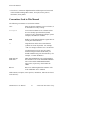
Conventions Used in This Manual
The following conventions are used in this manual:
italic
Italic text denotes emphasis, a cross reference, or
an introduction to a key concept.
monospace
Text in this font denotes text or characters that
are to be literally input from the keyboard,
sections of code, programming examples, syntax
examples, and names of variables.
bold
Bold text in this manual denotes a signal name or
a front panel LED indicator.
<>
Angle brackets enclose the ASCII character
symbols for certain keystrokes. For example,
<CR> for carriage return and <LF> for linefeed.
-
A hyphen between two or more key names
enclosed in angle brackets denotes that you
should simultaneously press the named keys–for
example, <Control-Alt-Delete>.
IEEE 488 and
IEEE 488.2
IEEE 488 and IEEE 488.2 are used throughout
this manual to refer to the ANSI/IEEE Standard
488.1-1987 and the ANSI/IEEE Standard
488.2-1987, respectively, which define the
GPIB.
RS-232
RS-232 is used throughout this manual to refer
to the ANSI/EIA-232-C standard.
Abbreviations, acronyms, metric prefixes, mnemonics, and terms are listed
in the Glossary.
GPIB-232CV User Manual
xii
© National Instruments Corp.
About This Manual
Related Documentation
The following documents contain information that you may find helpful as
you read this manual:
•
ANSI/EIA-232, Interface Between Data Terminal Equipment and
Data Circuit-Terminating Equipment Employing Serial Binary Data
Interchange.
•
ANSI/IEEE Standard 488.1-1987, IEEE Standard Digital Interface for
Programmable Instrumentation.
•
ANSI/IEEE Standard 488.2-1987, IEEE Standard Codes, Formats,
Protocols, and Common Commands.
Customer Communication
National Instruments wants to receive your comments on our products and
manuals. We are interested in the applications you develop with our
products, and we want to help if you have problems with them. To make it
easy for you to contact us, this manual contains comment and configuration
forms for you to complete. These forms are in Appendix D, Customer
Communication, at the end of this manual.
© National Instruments Corp.
xiii
GPIB-232CV User Manual
Chapter 1
Description of the GPIB-232CV
This chapter contains a brief overview of the GPIB-232CV, lists the
contents of your kit and optional equipment, and describes the panels of the
GPIB-232CV.
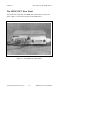
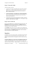
Introduction
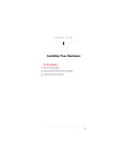
The GPIB-232CV, shown in Figure 1-1, provides a method of connecting a
device with a RS-232 port to the GPIB, or IEEE 488, bus. The
GPIB-232CV transparently converts data between the two ports so that
control codes or special commands are not required. The GPIB-232CV
also increases the efficiency of the interface system by isolating the slower
device from the faster port with a 256 KB character buffer. This buffer is
used to offload the host computer during printer and plotter applications.
Figure 1-1. The GPIB-232CV
© National Instruments Corp.
1-1
GPIB-232CV User Manual
Description of the GPIB-232CV
Chapter 1
The GPIB-232CV is capable of interfacing either a GPIB Controller or a
GPIB device to a computer or instrument with a RS-232 port. It can be
used to interface a GPIB device to a computer with a RS-232 port or to
connect a RS-232 device such as a printer or plotter to a GPIB network.
Data transfers in either direction are possible at all times.
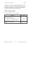
What Your Kit Contains
Your kit should contain the following components:
Component
Part Number
One of the following boxes:
•
GPIB-232CV (256 KB RAM - 115 VAC)
776174-02
•
GPIB-232CV (256 KB RAM - 230 VAC)
776174-32
GPIB-232CV User Manual
GPIB-232CV User Manual
320109-01
1-2
© National Instruments Corp.
Chapter 1
Description of the GPIB-232CV
Optional Equipment
Component
Part Number
Rack mount Kit:
Single (1 unit)
180480-01
Dual (2 units)
180480-02
RS-232 Shielded Cable, Compatible with IBM PC
DTE to DTE - 1 m
181074-10
25-pin male D-sub to 9-pin female D-sub
Double-Shielded GPIB Cables:
GPIB Type X2 Cable – 1 m
763061-01
GPIB Type X2 Cable – 2 m
763061-02
GPIB Type X2 Cable – 4 m
763061-03
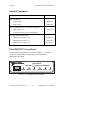
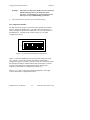
The GPIB-232CV Front Panel
The front panel of the GPIB-232CV is shown in Figure 1-2. The power
switch and six light-emitting diodes (LEDs) are mounted on the
GPIB-232CV front panel.
GPIB-232CV
IEEE 488
POWER READY
RS-232 CONVERTER
TALK
LISTEN BUSY
FULL
Figure 1-2. The GPIB-232CV Front Panel
© National Instruments Corp.
1-3
GPIB-232CV User Manual
Description of the GPIB-232CV
Chapter 1
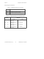
The LEDs show the current status of the GPIB-232CV at all times.
Table 1-1 describes each LED.
Table 1-1. LED Descriptions
LED
Indication
POWER
Indicates that power to the unit has been applied and the
ON/OFF switch is in the ON position.
READY
Indicates that the power-on self-test has passed successfully
and the unit is ready to operate.
TALK
Indicates that the GPIB-232CV is configured as a GPIB
Talker.
LISTEN
Indicates that the GPIB-232CV is configured as a GPIB
Listener.
BUSY
Indicates that the GPIB-232CV is currently accepting serial
data. Each serial character received toggles the status of
the BUSY LED.
FULL
Indicates that one of the GPIB-232CV data buffers is full.
This is not an error condition, but is merely a signal that
bus performance may be reduced to the speed of the slower
interface.
GPIB-232CV User Manual
1-4
© National Instruments Corp.
Chapter 1
Description of the GPIB-232CV
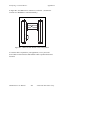
The GPIB-232CV Rear Panel
The power cord, serial cable, and GPIB cable connections are on the rear
panel. Figure 1-3 shows the rear panel of the GPIB-232CV.
Figure 1-3. The GPIB-232CV Rear Panel
© National Instruments Corp.
1-5
GPIB-232CV User Manual
Description of the GPIB-232CV
Chapter 1
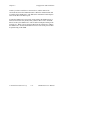
The RS-232 Connector
The RS-232 port on the GPIB-232CV is configured as a DTE (Data
Terminal Equipment) and uses a standard 25-pin shielded D-subminiature
female connector with screwlock assemblies. The RS-232 connector will
accept standard 25-pin D-subminiature male connectors. A diagram of the
serial connector and the signals supported is shown in Figure 1-4. For more
information on the RS-232 signals refer to Appendix B, Interfacing to a
Serial Device.
NC
NC
NC
NC
NC
RTS
RXD
2 1
NC
GND
3
NC
NC
4
DTR
6 5
NC
7
NC
NC
8
NC
13 12 11 10 9
NC
25 24 23 22 21 20 19 18 17 16 15 14
NC
TXD
NC
NC
NC
NC
CTS
GND
Figure 1-4. The RS-232 Connector and Signal Designations
GPIB-232CV User Manual
1-6
© National Instruments Corp.
Chapter 1
Description of the GPIB-232CV
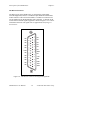
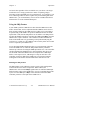
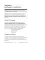
The GPIB Connector
The GPIB connector is a standard 24-pin shielded AMP Champ female
connector with metric screwlock hardware. A diagram of the GPIB
connector and the signals supported is shown in Figure 1-5 (a * suffix
indicates that the signal is active low).
DIO1*
DIO2*
DIO3*
DIO4*
EOI*
DAV*
NRFD*
NDAC*
IFC*
SRQ*
ATN*
SHIELD
1
2
3
4
5
6
7
8
9
10
11
12
13
14
15
16
17
18
19
20
21
22
23
24
DIO5*
DIO6*
DIO7*
DIO8*
REN*
GND (Twisted Pair with DAV*)
GND (Twisted Pair with NRFD*)
GND (Twisted Pair with NDAC*)
GND (Twisted Pair with IFC*)
GND (Twisted Pair with SRQ*)
GND (Twisted Pair with ATN*)
SIGNAL GROUND
Figure 1-5. The GPIB Connector and Signal Designations
© National Instruments Corp.
1-7
GPIB-232CV User Manual
Chapter 2
Configuration and Installation
This chapter describes the procedures for configuring and installing the
GPIB-232CV.
As mentioned in Chapter 1, the GPIB-232CV can be configured either as a
GPIB Controller capable of addressing a single GPIB device to talk or
listen, or as a GPIB device that can be addressed to talk or listen by a GPIB
Controller.
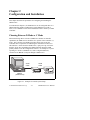
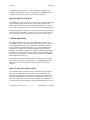
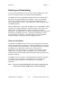
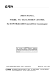
Choosing Between D Mode or C Mode
When transferring data to or from a GPIB device that has no controller
capabilities, the GPIB-232CV should be set to operate in the Controller (C)
mode. This is because in a GPIB system there must exist at least one
Controller that is responsible for addressing the instruments on the bus to
talk and listen. In this mode the GPIB-232CV, upon power-up, will assert
Interface Clear (IFC) and address the GPIB instrument using the GPIB
primary address set on the configuration switches. An example of a system
operating in C mode is a GPIB device, such as a digital multimeter,
connected to an IBM PC serial port through a GPIB-232CV.
Serial
Cable
GPIB
Cable
GPIB-422CV
IEEE 488
POWER READY
IBM PC
(Serial Device)
RS-422 CONVERTER
TALK
LISTEN BUSY
FULL
GPIB-232CV
Digital Multimeter
(GPIB Device)
Figure 2-1. Example of C Mode System Setup
© National Instruments Corp.
2-1
GPIB-232CV User Manual
Configuration and Installation
Chapter 2
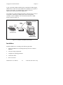
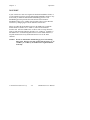
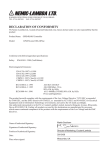
If your system has a GPIB Controller that is responsible for addressing the
GPIB-232CV to talk or listen, the GPIB-232CV should be set to operate in
the Device (D) mode. It is called the Device mode because the
GPIB-232CV functions like another GPIB device.
An example of a system operating in D mode is a RS-232 device, such as a
serial printer, connected to a GPIB system with an existing GPIB
Controller, such as an IBM PC with a National Instruments AT-GPIB
board, as shown in Figure 2-2.
GPIB Device
GPIB
Cables
Serial
Cable
GPIB-422CV
IEEE 488
POWER
Printer
(Serial Device)
READY
RS-422 CONVERTER
TALK
LISTEN
BUSY
FULL
GPIB-232CV
IBM PC AT
(GPIB Controller)
Figure 2-2. Example of D Mode System Setup
Installation
Install the GPIB-232CV according to the following procedure.
1.
Inspect the GPIB-232CV for damage that may have been caused in
shipment.
2.
Verify the voltage requirement.
3.
Configure the operating parameters.
4.
Connect the cables.
5.
Power on the unit.
GPIB-232CV User Manual
2-2
© National Instruments Corp.
Chapter 2
Configuration and Installation
Step 1. Inspection
Before you install the GPIB-232CV, inspect the shipping container and its
contents for damage. If damage appears to have been caused in shipment,
file a claim with the carrier. Retain the packing material for possible
inspection and/or reshipment.
If the equipment appears to be damaged, do not attempt to operate it.
Contact National Instruments for instructions.
Step 2. Verify the Voltage Requirement
The GPIB-232CV is shipped from the factory with either a 115V or 230V
wall-mount supply. Verify that the voltage on the supply matches the
voltage that is supplied in your area.
Warning:
Operating the unit at any voltage other than the one
specified could damage the unit.
Step 3. Configure the Operating Parameters
The GPIB-232CV is shipped from the factory configured to operate in D
mode and is set to GPIB primary address 5. The serial port is configured at
9600 baud, 1 stop bit, no parity, and 7 data bits with XON/XOFF protocol
disabled. If you wish to change any of the GPIB-232CV parameters, you
must open the unit and set the configuration switches. To change the
configuration switches follow these steps:
1.
Disconnect power to the unit and disconnect any cables that may be
connected to the unit.
2.
Unscrew the two screws on the opposite sides of the rear panel.
3.
Grab the rear panel bezel and pull it straight away from the rest of the
unit. The card should slide out the back of the enclosure.
4.
Locate the configuration DIP switches (U20 and U22) on the printed
wire board.
5.
Set the switches for the desired mode of operation, as described in the
following section, Set Configuration Switches.
© National Instruments Corp.
2-3
GPIB-232CV User Manual
Configuration and Installation
Warning:
6.
Chapter 2
Most of the circuitry in the GPIB-232CV uses advanced
CMOS technology and can be damaged by static
electricity. Avoid touching any of the components and
take any necessary CMOS handling precautions.
Close the unit and re-insert the screws removed in Step 2.
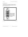
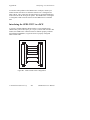
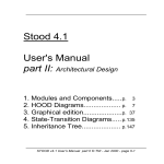
Set Configuration Switches
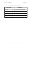
The DIP switches at location U20 and U22 on the printed wire board are
used to configure the GPIB-232CV. The DIP switch at location U22 is
used to configure the mode of the GPIB-232CV as well as the address of
the GPIB device. The DIP switch, shown in Figure 2-3, has eight
configuration switches.
U22
1
2
3
4
5
6
7
8
O
N
O
F
F
Figure 2-3. Factory Default Settings for Switch U22
Figure 2-3 shows the GPIB-232CV's factory default settings for switch
U22. Switch 1 is in the OFF position; this indicates that the unit is
configured to operate in D mode. Switches 2 and 3 are in the OFF position;
this indicates that SRQ is disabled and the small serial buffer is selected.
Switches 4 through 8 are in the OFF OFF ON OFF ON positions,
respectively; this indicates a GPIB primary address of 5.
Tables 2-1, 2-2, and 2-3 show the possible configurations of the eight
switches and what the configurations indicate.
GPIB-232CV User Manual
2-4
© National Instruments Corp.
Chapter 2
Configuration and Installation
Default settings are in shaded rows.
Table 2-1. Configuration Parameters for U22 Switch 1
Switch 1
Position
Indication
OFF
GPIB-232CV operates in D mode.
ON
GPIB-232CV operates in C mode .
Table 2-2. Configuration Parameters for U22 Switches 2 and 3
Switches
2
3
Indication
D Mode
C Mode
OFF
OFF
Small serial buffer and
disable SRQ
Time-out termination
OFF
ON
Small serial buffer and
enable SRQ
CR termination
ON
OFF
Large serial buffer and
disable SRQ
LF termination
ON
ON
Large serial buffer and
enable SRQ
No swapping
© National Instruments Corp.
2-5
GPIB-232CV User Manual
Configuration and Installation
Chapter 2
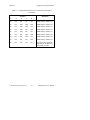
Table 2-3. Configuration Parameters for U22 Switches 4 through 8
Switches
6
7
Indication
4
5
OFF
OFF
OFF
OFF
OFF
GPIB Primary Address 0
OFF
OFF
OFF
OFF
ON
GPIB Primary Address 1
OFF
OFF
OFF
ON
OFF
GPIB Primary Address 2
OFF
OFF
OFF
ON
ON
GPIB Primary Address 3
OFF
OFF
ON
OFF
OFF
GPIB Primary Address 4
OFF
OFF
ON
OFF
ON
GPIB Primary Address 5
OFF
OFF
ON
ON
OFF
GPIB Primary Address 6
OFF
OFF
ON
ON
ON
GPIB Primary Address 7
OFF
ON
OFF
OFF
OFF
GPIB Primary Address 8
OFF
ON
OFF
OFF
ON
GPIB Primary Address 9
OFF
ON
OFF
ON
OFF
GPIB Primary Address 10
OFF
ON
OFF
ON
ON
GPIB Primary Address 11
OFF
ON
ON
OFF
OFF
GPIB Primary Address 12
OFF
ON
ON
OFF
ON
GPIB Primary Address 13
OFF
ON
ON
ON
OFF
GPIB Primary Address 14
OFF
ON
ON
ON
ON
GPIB Primary Address 15
ON
OFF
OFF
OFF
OFF
GPIB Primary Address 16
ON
OFF
OFF
OFF
ON
GPIB Primary Address 17
ON
OFF
OFF
ON
OFF
GPIB Primary Address 18
ON
OFF
OFF
ON
ON
GPIB Primary Address 19
ON
OFF
ON
OFF
OFF
GPIB Primary Address 20
ON
OFF
ON
OFF
ON
GPIB Primary Address 21
ON
OFF
ON
ON
OFF
GPIB Primary Address 22
2-6
© National Instruments Corp.
GPIB-232CV User Manual
8
Chapter 2
Configuration and Installation
Table 2-3. Configuration Parameters for U22 Switches 4 through 8
(continued)
4
5
Switches
6
7
Indication
8
ON
OFF
ON
ON
ON
GPIB Primary Address 23
ON
ON
OFF
OFF
OFF
GPIB Primary Address 24
ON
ON
OFF
OFF
ON
GPIB Primary Address 25
ON
ON
OFF
ON
OFF
GPIB Primary Address 26
ON
ON
OFF
ON
ON
GPIB Primary Address 27
ON
ON
ON
OFF
OFF
GPIB Primary Address 28
ON
ON
ON
OFF
ON
GPIB Primary Address 29
ON
ON
ON
ON
OFF
GPIB Primary Address 30
ON
ON
ON
ON
ON
Sets listen-only operation
(D mode) or no addressing
performed (C mode)
© National Instruments Corp.
2-7
GPIB-232CV User Manual
Configuration and Installation
Chapter 2
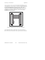
The DIP switch at location U20 on the printed wire board is used to
configure the serial port parameters of the GPIB-232CV. The DIP switch,
shown in Figure 2-4, has eight configuration switches.
U20
1
2
3
4
5
6
7
8
O
N
O
F
F
Figure 2-4. Factory Default Settings for Switch U20
On DIP switch U20, switch 1 is OFF, indicating that XON/XOFF is
disabled. Switch 2 is OFF, indicating that the GPIB-232CV will be using 7
bits/character for its serial data transfers. Switch 3 is OFF, which indicates
1 stop bit per character. Switches 4 and 5 are both OFF, which indicates
that parity is disabled. Switches 6 through 8 are in the ON OFF ON
positions, respectively, indicating that the serial port will be operating at
9600 baud.
Tables 2-4 and 2-5 show the possible configurations of the eight switches
and what the configurations indicate.
GPIB-232CV User Manual
2-8
© National Instruments Corp.
Chapter 2
Configuration and Installation
Table 2-4. Configuration Parameters for U20 Switches 1 through 5
Switch
1
2
3
4
5
Position
Indication
OFF
XON/XOFF protocol disabled
ON
XON/XOFF protocol enabled
OFF
7 bits/character
ON
8 bits/character
OFF
1 stop bit/character
ON
2 stop bits/character
OFF
parity generation/checking disabled
ON
parity generation/checking enabled
OFF
odd parity
ON
even parity
Table 2-5. Configuration Parameters for U20 Switches 6 through 8
6
Switches
7
8
OFF
OFF
OFF
300 baud
OFF
OFF
ON
600 baud
OFF
ON
OFF
1200 baud
OFF
ON
ON
2400 baud
ON
OFF
OFF
4800 baud
ON
OFF
ON
9600 baud
ON
ON
OFF
19200 baud
ON
ON
ON
38400 baud
© National Instruments Corp.
Indication
2-9
GPIB-232CV User Manual
Configuration and Installation
Chapter 2
Step 4. Connect the Cables
Connect the cables as follows:
1.
Connect the serial cable to the GPIB-232CV and securely fasten the
holding screws. Connect the other end of the cable to your serial
device. Be sure to use only shielded serial cable, and follow all
RS-232 cabling restrictions.
2.
Connect the GPIB cable to the GPIB-232CV and tighten the thumb
screws on the connector. Connect the other end to your GPIB system.
Be sure to follow all IEEE 488 cabling restrictions, and use only
double-shielded GPIB cable.
3.
Connect the power jack of the wall-mount power supply to the power
receptacle on the back panel of the GPIB-232CV, then plug the supply
into an AC outlet of the correct voltage.
Step 5. Power on the Unit
Power on your GPIB-232CV by using the front panel rocker switch. The
POWER LED should come on immediately. The READY indicator
should come on after the GPIB-232CV has passed its power-on self-test,
indicating the unit is ready for operation.
If the READY indicator does not come on within seven seconds after the
unit is powered on, recheck all connections and switch settings and retry the
power-on sequence. If the READY light still fails to come on, contact
National Instruments for further instructions.
Operation
The GPIB-232CV is now ready to operate. All characters sent to the unit
will be received at full speed and stored in the internal data buffer. The
characters will be sent to the receiving device at the rate of the receiving
device.
If using the GPIB-232CV in C mode, turn on the GPIB instrument before
turning on the GPIB-232CV and be sure the configuration switches are set
correctly. When the GPIB-232CV is powered on, it will send IFC and
address the instrument to listen. Simply send data to your serial port as you
GPIB-232CV User Manual
2-10
© National Instruments Corp.
Chapter 2
Configuration and Installation
would if you had a serial device connected to it, and the data will be
converted and sent to the GPIB instrument. When the instrument has data
to send back, the GPIB-232CV will address the instrument to talk and pass
all received data to the RS-232 port.
If using the GPIB-232CV in D mode, simply address the GPIB-232CV to
listen (if not in listen-only mode) when you have data to send. All GPIB
data received by the GPIB-232CV will be buffered and passed along to the
serial device. When you are expecting data from the serial device, address
the GPIB-232CV to talk, and all data received over the serial port will then
be passed along to the GPIB.
© National Instruments Corp.
2-11
GPIB-232CV User Manual
Chapter 3
Operation
This chapter contains information about operating the GPIB-232CV in D
mode or C mode and information about data buffering and handshaking.
The GPIB-232CV is actually a powerful 8-bit microcomputer tailored for
use as an IEEE 488-to-RS-232 protocol converter. The unit's operating
system is contained in Read-Only Memory (ROM) and can address up to
256 KB of dynamic Random-Access Memory (RAM). The GPIB-232CV
microprocessor contains an integrated Direct Memory Access (DMA)
Controller for high-speed data transfers from the GPIB circuitry. The
processor also contains an integrated memory management unit, a dynamic
RAM Controller, a clock generator, a programmable timer unit, a full
duplex UART (Universal Asynchronous Receiver Transmitter), and an
interrupt controller.
The serial port has been designed to be fully compatible with all electrical
specifications in the RS-232 standard. All GPIB functionality is provided
by an LSI GPIB Controller chip, which is programmed and maintained by
the operating system. Both the serial port and the GPIB port are interrupt
driven and feature extremely fast response times to external data transfers.
For more information on how the individual modes of operation work, refer
to the following discussions.
The following terms are specific to the discussions in this chapter:
•
A * suffix after a mnemonic indicates negative logic.
•
A boldface mnemonic indicates that it is a signal name, or a front panel
LED indicator.
•
<CR> is the symbol for the Carriage Return character (hex 0D).
•
<LF> is the symbol for the Linefeed character (hex 0A).
© National Instruments Corp.
3-1
GPIB-232CV User Manual
Operation
Chapter 3
D Mode Operation
In D mode, the GPIB-232CV can act only as a GPIB Talker or Listener.
The GPIB-232CV should not be passed control. If it is, the GPIB circuitry
in the GPIB-232CV will accept control and immediately assert ATN*.
This is an error condition that can lock up your system and should therefore
be avoided.
Data Transfers and Buffering
When operating in D mode, the GPIB-232CV accepts data from the GPIB
port using the onboard DMA Controller. The DMA Controller transfers the
data directly to the memory buffer without processor intervention. As a
result, very high-speed GPIB transfer rates are possible—as high as 900
kbytes/sec. This means that the GPIB system performance will not be
degraded by connecting a "slow" printer or plotter to the interface. The
buffered data is then dumped to the device on the RS-232 port at its own
rate. These two asynchronous events take place concurrently and without
user interaction. All operations are completely transparent to the user.
Any serial data that is sent to the GPIB-232CV will be buffered and then
passed along to the GPIB port whenever the GPIB-232CV is addressed to
talk. Depending upon how much data, if any, is expected to be sent to the
GPIB-232CV, via the serial port, two different serial port input buffer sizes
can be used for maximum efficiency. The size of the serial input buffer can
be set to either 256 bytes (U22 switch 2 set to OFF), or 32 KB (U22 switch
2 set to ON). The serial input buffer size should be set to 256 bytes if only
small amounts of data, such as status information, are expected to be sent
from the serial device to the GPIB-232CV. The serial input buffer size
should probably be set to 32 KB if large amounts of data are expected to be
sent from the serial device to the GPIB-232CV, such as an RS-232
instrument sending thousands of bytes of measurements.
Choosing a Serial Port Buffer Size
Whether you use a 256-byte or 32 KB buffer size, the remainder of the
RAM space is used as the GPIB input buffer. Thus, if a large amount of
GPIB data is expected to be sent to the GPIB-232CV it would be
advantageous to use the small serial port buffer size if possible. Remember
that because the GPIB-232CV implements a hardware handshake scheme as
well as the XON/XOFF software handshake scheme if selected, serial data
GPIB-232CV User Manual
3-2
© National Instruments Corp.
Chapter 3
Operation
will not be lost regardless of the serial buffer size you choose. The larger
serial buffer size is simply provided as a means of capturing a larger
percentage of the total RAM space for serial-input use. For example, if you
were connecting an RS-232 device capable only of transmitting data to the
GPIB-232CV, you would definitely want to use the 32 KB serial buffer to
maximize the use of the available RAM space.
Using the SRQ Feature
If your GPIB system has GPIB devices other than the GPIB-232CV that
need to transfer data, and it is important that the GPIB bus not be slowed
down or hung waiting for the GPIB-232CV to either receive serial data to
be passed along to the GPIB or accept more GPIB data because its GPIB
input buffer is full, then the SRQ feature can be enabled. The SRQ feature
will alert the GPIB Controller by asserting the GPIB signal SRQ* when the
GPIB-232CV requires attention. The Controller can then determine the
status of the GPIB-232CV by performing a serial poll and analyzing the
response byte. In this way, the GPIB bus can be used by other devices until
service is required by the GPIB-232CV.
To get maximum GPIB performance when very large amounts of data are
sent to the GPIB-232CV, enable the SRQ feature and only send data
amounts up to but not exceeding the GPIB input buffer size. The Controller
can then unaddress the GPIB-232CV to listen and allow other devices to
use the GPIB. When the GPIB-232CV has emptied out its GPIB input
buffer, it will request service, indicating it is ready for more data. The
Controller can then re-address the GPIB-232CV to listen and continue
sending data in the manner described until all the data has been sent.
Enabling the SRQ Feature
The SRQ feature can be enabled by setting switch 3 of the configuration
switch at location U22 to the ON position. When enabled, the
GPIB-232CV will assert the SRQ* signal whenever either the GPIB input
buffer becomes empty or the GPIB-232CV receives serial data that it needs
to pass on to the GPIB port. SRQ* will be unasserted when the GPIB
Controller performs a serial poll on the GPIB-232CV.
© National Instruments Corp.
3-3
GPIB-232CV User Manual
Operation
Chapter 3
Conditions that Assert SRQ
When the SRQ feature is enabled, one of the conditions that causes a
service request is when the GPIB-232CV serial input buffer is empty.
Then, the GPIB-232CV receives a serial character to be sent along to the
GPIB. The SRQ* signal is asserted to alert the GPIB Controller that the
GPIB-232CV has data to send to a GPIB Listener. The GPIB-232CV can
then be addressed to talk so that the data can be read out of the
GPIB-232CV serial buffer. After all data has been read, the Controller can
unaddress the GPIB-232CV to talk so that other devices can be addressed to
transfer data on the bus.
The other condition on which SRQ* will be asserted, if enabled, is when
the GPIB input buffer becomes empty. If very large amounts of data are
sent over the GPIB to the GPIB-232CV (greater than the GPIB buffer size)
and the serial device is a very slow data acceptor, the GPIB-232CV internal
GPIB data buffer might become full. If this does occur, the FULL
indicator on the front panel will illuminate and the GPIB transfer rate will
slow to approximately the same rate as the serial device accepting the data.
Since the maximum data transfer rate on the GPIB is only as fast as the
slowest Listener, the GPIB system performance may become unacceptable
if other GPIB devices need to transfer data on the bus.
Serial Poll Responses
If the GPIB-232CV is serial polled, its response byte will depend upon the
status of the internal data buffers. If the serial input buffer is empty, bit one
of the status byte will be set to 1. If the serial input buffer is not empty, bit
one will be set to 0. If the GPIB input buffer is empty, bit zero of the status
byte will be set to 1. If the GPIB input buffer is not empty, bit one will be
set to 0. In all cases, bit six will be set to 1 if the GPIB-232CV is
requesting service, and will be set to 0 otherwise.
Listen-Only Mode
The GPIB-232CV will be located at the GPIB address specified by switches
4 through 8 of the configuration DIP switch at location U22. The
GPIB-232CV also has the ability to be configured as a listen-only device if
all GPIB address switches are set to ON. In the listen-only mode, no
addressing is required to make the GPIB-232CV a GPIB Listener and it
cannot be unaddressed to listen. All data transferred on the GPIB will be
accepted by the GPIB-232CV and output to the serial port (even if the data
GPIB-232CV User Manual
3-4
© National Instruments Corp.
Chapter 3
Operation
was intended for another device). This configuration could be used to
monitor all GPIB data bus activity. Notice that when the GPIB-232CV is
configured as a listen-only device, it may not be serial polled.
Special Conditions in D Mode
If the GPIB-232CV receives the universal Device Clear (DCL) command or
its listen address and the Selected Device Clear (SDC) command, the
GPIB-232CV will clear its internal data buffers and reset to its power-up
state. Neither Trigger nor Go To Local has any effect on the GPIB-232CV.
In D mode operation, the GPIB-232CV does not assert EOI when sending
characters along to the GPIB. You can use bit 1 of the serial poll response
byte to determine if there are characters waiting to be sent to the GPIB.
C Mode Operation
In C mode, the GPIB-232CV acts as the GPIB System Controller and
asserts IFC* for 500 µs when the GPIB-232CV is powered on. The action
of asserting IFC* for at least 100 µs initializes the GPIB and makes the
System Controller Controller-In-Charge (CIC). After the GPIB-232CV
becomes CIC, it sends out the GPIB listen address on U22 switches 4
through 8. If all address configuration switches are ON, no addressing will
be performed. This is useful if you are talking to a listen-only device that
does not require addressing. The GPIB-232CV will always assert REN*
when addressing other devices.
All incoming serial data to the GPIB-232CV is stored in an internal data
buffer until it is accepted by the GPIB device. All GPIB data sent to the
GPIB-232CV is passed immediately to the serial port without being
buffered.
Modes of Operation within C Mode
Four different modes of operation within C mode define how the GPIB
device is to be addressed—time termination, <CR> termination, <LF>
termination, and no-swap. In all modes, the GPIB device is addressed to
listen after the GPIB-232CV becomes CIC and all data received via the
serial port is buffered. The data is then passed along to the GPIB device.
The four modes of operation define at what point the GPIB device needs to
© National Instruments Corp.
3-5
GPIB-232CV User Manual
Operation
Chapter 3
be unaddressed to listen and addressed to talk so that data can be sent from
the GPIB device to the GPIB-232CV.
Time Termination Mode
In time termination mode, the GPIB-232CV will address the GPIB device
to talk if the GPIB-232CV serial input buffer becomes empty and no more
serial characters are received for 300 ms. After this period of inactivity, the
GPIB-232CV assumes that since no more serial data is being sent, the
GPIB device might have data that it needs to send back to the
GPIB-232CV. Any characters read from the GPIB port at this time will
immediately be passed along to the serial port. When a serial character is
received by the GPIB-232CV, it immediately re-addresses the GPIB device
to listen and passes the received character to it. It will remain in this mode
until its serial-input buffer becomes empty and no serial characters are
received for 300 ms, at which time it will re-address the GPIB device to
talk.
Time termination mode should be used for applications in which
bidirectional communication is required and neither a <CR> or <LF>
character is used to signal the end of a command string to the GPIB device.
<CR> or <LF> Termination Mode
If a command string to the GPIB instrument can be terminated with either a
<CR> or <LF> character, you can use either <CR> or <LF> termination
mode to address the GPIB device to send data. In these modes, when the
GPIB-232CV receives the terminating character, it will address the GPIB
device to talk so that any GPIB data can be input by the GPIB-232CV. Any
serial character received by the GPIB-232CV at this point will signal the
GPIB-232CV to re-address the GPIB device as a Listener. For example,
let's say you wish to connect an HP7475 GPIB plotter to an IBM-PC serial
port via the GPIB-232CV and you want to draw a line, get plotter status,
and then draw a circle. In BASIC, this could be done with the following
commands:
GPIB-232CV User Manual
3-6
© National Instruments Corp.
Chapter 3
Operation
10 OPEN "COM1:9600,n,8,1" AS #1
'Assumes
'GPIB-232CV is
'at 9600 baud,
'no parity, 8
'data bits, 1
'stop bit.
20 PRINT #1,"pa1000,1000 os"
'Plot absolute to
'1000,1000 then
'output status.
30 LINE INPUT #1,RESPONSE$
'Get status
'response from
'plotter.
40 PRINT #1 "ci100";
'Draw circle
'with radius of
'100 units.
Notice that on line 20, the program outputs plotter commands to the serial
port to both draw a line and obtain status. Since neither a <CR> nor <LF>
was sent between these commands, the GPIB-232CV will keep the GPIB
plotter addressed to listen and will send all serial data received to the
plotter. Since the PRINT statement is not ended with a semicolon after the
double quotation mark, BASIC will automatically send a <CR> after the
last character in the ASCII string has been sent. Therefore, if the
GPIB-232CV is set up for <CR> termination, the GPIB-232CV would at
this time re-address the plotter to talk so that the status could be output.
Line 30 will input the status response from the plotter into a string variable
RESPONSE$. Line 40 will then output the plotter command to draw a
circle to the GPIB-232CV. As soon as the GPIB-232CV receives the first
character in this string, it will re-address the plotter to listen before sending
these characters to the plotter. Notice that for this PRINT statement a
semicolon was included after the last double quotation mark so that a <CR>
will not be sent. Since information was not requested from the plotter, there
is no need to send a <CR> at the end of the string to address the plotter to
talk.
No-Swap Mode
In the last mode, no-swap, the GPIB-232CV will never re-address the GPIB
device after it has initially addressed it to be a Listener. This mode is useful
if your GPIB device is intended only to receive data. In the above example,
you could use the no-swap mode to talk to the plotter if you never need to
obtain status information from it.
© National Instruments Corp.
3-7
GPIB-232CV User Manual
Operation
Chapter 3
Buffering and Handshaking
Two protection mechanisms are used to ensure that the GPIB-232CV does
not lose incoming serial data: data buffering and handshaking.
The GPIB-232CV has an internal RAM buffer that stores incoming serial
data until it can output the data to the GPIB port. The size of this RAM
buffer, in part, determines how much serial data the GPIB-232CV can
accept until its buffer overflows. The GPIB-232CV comes equipped with a
256 KB RAM buffer.
When its RAM buffer is nearly full, the GPIB-232CV can handshake with the
serial host to stop data transmission. When the buffer is almost empty, the
GPIB-232CV can again handshake with the serial host to start data
transmission. The GPIB-232CV is capable of using both the XON/XOFF and
the hardware handshaking protocols. The hardware handshake is always
active during RS-232 transfers. The XON/XOFF protocol is enabled or
disabled by properly setting the internal configuration switch.
Hardware Handshake
The hardware handshake function is always active during RS-232 transfers
and uses the RTS and CTS signal lines. When the GPIB-232CV is ready to
accept serial data, it asserts the RTS line. This signal remains asserted until
the GPIB-232CV's data buffer is almost full. At this point, the
GPIB-232CV unasserts the RTS line, signaling to the serial host that the
GPIB-232CV is no longer ready to accept data. The serial host should
monitor the RTS line and suspend data transmission whenever the RTS line
becomes unasserted.
The GPIB-232CV is also able to suspend transmission when the serial host
is no longer ready to accept data. The GPIB-232CV is configured to
immediately stop transmission of serial data when CTS becomes
unasserted.
Note:
If you use a serial cable that does not connect to CTS, CTS will
not be asserted and the GPIB-232CV will not transmit data.
GPIB-232CV User Manual
3-8
© National Instruments Corp.
Chapter 3
Operation
XON/XOFF
If your serial device does not recognize the hardware handshake scheme, or
if your application software uses the XON/XOFF handshake scheme, it may
be necessary to enable the XON/XOFF handshaking protocol. This
handshaking protocol performs the same function as the hardware
handshake but does so by sending special control codes over the data lines
instead of by changing logic levels on dedicated control lines.
When you enable the XON/XOFF protocol, the GPIB-232CV sends the
XOFF character (decimal 19 or <CTRL>s) when its internal buffer
becomes full. Once the GPIB-232CV is able to start receiving characters
again, it sends the XON character (decimal 17 or <CTRL>q). Similarly, if
the GPIB-232CV is transmitting data and receives the XOFF character, it
suspends transmission of any further data until it receives the XON
character.
Caution: Do not use XON/XOFF handshaking if you are transmitting
binary data. Because your data could include decimal 17 or 19
(<CTRL>q or <CTRL>s), the GPIB-232CV might handshake
erratically.
© National Instruments Corp.
3-9
GPIB-232CV User Manual
Appendix A
Hardware Specifications
This appendix lists the electrical, environmental, and physical specifications
of the GPIB-232CV.
Table A-1. Electrical Characteristics
Characteristic
Specification
Power Supply Unit
Wall mount type, 115 VAC or 230 VAC,
50/60 Hz input, 9 VDC @ 1A max output
Voltage
9 VDC regulated
Current
640 mA typical; 750 mA max
Table A-2. Environmental Characteristics
Characteristic
Specification
Operating Temperature
10° to 40° C
Storage Temperature
0° to 70° C
Relative Humidity
10% to 95% noncondensing conditions
Noise Emissions
FCC Class A Verified
© National Instruments Corp.
A-1
GPIB-232CV User Manual
Hardware Specifications
Appendix A
Table A-3. Physical Characteristics
Characteristic
Specification
Case Size
1.6 in. by 5.7 in. by 8.4 in. (40.6 mm by
144.8 mm by 213.4 mm)
Case Material
All metal enclosure
Rack Mounting
Single or dual kits available
Weight
28 oz. (without power supply unit)
GPIB-232CV User Manual
A-2
© National Instruments Corp.
Appendix B
Interfacing to a Serial Device
This appendix contains information about the RS-232 port and how to
connect the GPIB-232CV to your serial device. This information is useful
if you want to build your own serial cable
The GPIB-232CV transfers serial data using the electrical signals, the
mechanical connections, and the data format and control protocols as
defined in the RS-232C standard. The RS-232 port on the GPIB-232CV
provides an asynchronous serial communication link to the host serial
peripheral device. The RS-232 connector is located on the rear panel of the
GPIB-232CV.
The RS-232C Standard
The RS-232C standard (international standard CCITT V.24) was
formulated in 1969 largely from the efforts of the Electronic Industries
Association (EIA) and Bell Laboratories. The standard describes the
electrical specifications and arrangement of control and data signals on both
sides of a serial communications interface. Its original intent was to
interface terminals to modems. Many manufacturers of computers and
instruments have adopted the standard for their serial communications
needs. For more information on the RS-232 standard, contact
Global Engineering Documents
2805 McGaw Avenue
Irvine, CA 92714
(714) 261-1455
The RS-232C Serial Port
The RS-232 serial port on the GPIB-232CV uses a female 25-pin
D-subminiature connector with a DTE (Data Terminal Equipment) interface
configuration. That is, the GPIB-232CV transmits data on pin 2 and
receives data on pin 3. Table B-1 shows the signal lines supported on the
GPIB-232CV.
© National Instruments Corp.
B-1
GPIB-232CV User Manual
Interfacing to a Serial Device
Appendix B
Table B-1. RS-232 Serial Port Signals
RS-232
Name
Pin
AA
1
PG
(Protective
Ground)
This line is connected to the chassis
ground of the GPIB-232CV. Since
the chassis ground is not connected
to earth ground, pin 1 should be
connected on both serial devices.
BA
2
TxD
(Transmit Data)
This line carries serial data from the
GPIB-232CV to the serial host.
BB
3
RxD
(Receive Data)
This line carries serial data from the
serial host to the GPIB-232CV.
CA
4
RTS
(Request to
Send)
This signal line is driven by the
GPIB-232CV and when asserted
indicates that the GPIB-232CV is
ready to accept serial data. The
GPIB-232CV unasserts RTS when it
is no longer ready to accept serial
data because the buffer is full.
CB
5
CTS
(Clear to Send)
This signal line is asserted by the
serial host and sensed by the
GPIB-232CV. When asserted, it
indicates that the serial host is ready
to accept serial data. When
unasserted, it indicates that data
transmission should be disabled.
AB
7
SG
(Signal Ground)
This line establishes a reference
point for all interface voltages.
CD
20
DTR
(Data Ready)
This signal line is asserted by the
GPIB-232CV to signal that it has
been powered on and is ready to
operate.
Signal Name
GPIB-232CV User Manual
Function
B-2
© National Instruments Corp.
Appendix B
Interfacing to a Serial Device
To interface other products to the GPIB-232CV serial port, consult your
manual on that serial device to determine if the device is configured as a
DTE or DCE. Also, notice how the control lines are used and whether they
must be driven for the serial port to operate. The GPIB-232CV CTS signal
is configured so that it must be asserted for the GPIB-232CV to transmit
data.
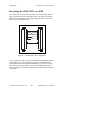
Interfacing the GPIB-232CV to a DCE
A correctly configured DTE-to-DCE interface is wired straight across:
GPIB-232CV pin 2 to DCE pin 2, pin 3 to pin 3, and so forth. Wired in this
manner, the GPIB-232CV can then interact to function properly on buffer
full conditions (handshake). Figure B-1 shows a properly configured
DTE-to-DCE cable.
1
2
3
4
5
1
2
3
4
5
7
7
20
20
Figure B-1. DTE-to-DCE Cable Configuration
© National Instruments Corp.
B-3
GPIB-232CV User Manual
Interfacing to a Serial Device
Appendix B
If your serial device does not use the same hardware handshaking protocol
as the GPIB-232CV, you can either use a minimum configuration cable and
use XON/XOFF handshaking (if necessary), or wire a custom cable that
will satisfy the GPIB-232CV hardware handshaking protocol. The
connections for a minimum configuration cable are shown in Figure B-2.
The GPIB-232CV connector is on the left. (Assumes that the DCE's
handshaking is satisfied internally.)
1
2
3
7
1
2
3
7
5
20
Figure B-2. Minimum DTE-to-DCE Cable Configuration
If your application requires a custom cable, review your serial device's
RS-232 characteristics and build the cable to perform the desired functions.
GPIB-232CV User Manual
B-4
© National Instruments Corp.
Appendix B
Interfacing to a Serial Device
Interfacing the GPIB-232CV to a DTE
For serial devices set up as DTEs, you must wire a DTE-to-DTE interface
cable, commonly known as a null modem cable. The cable must fool the
GPIB-232CV into thinking it is communicating with a DCE. Figure B-3
shows a typical null modem cable.
1
2
3
4
5
1
2
3
4
5
7
7
Figure B-3. Null Modem Cable Configuration
If your serial device does not use the same hardware handshaking protocol
as the GPIB-232CV, you can either use a minimum configuration null
modem cable and use XON/XOFF handshaking, or you can use a custom
cable that will satisfy the GPIB-232CV hardware handshaking protocol.
The connections for a minimum configuration null modem cable are shown
in Figure B-4.
© National Instruments Corp.
B-5
GPIB-232CV User Manual
Interfacing to a Serial Device
Appendix B
In Figure B-4, the GPIB-232CV connector is on the left. (Assumes the
serial device's handshake is satisfied internally.)
1
2
3
7
1
2
3
7
5
20
Figure B-4. Minimum Null Modem Cable Configuration
If a custom cable is required for your application, review your serial
device's RS-232 characteristics and build the cable to perform the desired
functions.
GPIB-232CV User Manual
B-6
© National Instruments Corp.
Appendix C
Application Examples
This appendix contains two GPIB-232CV application examples. The first
example shows how to use the GPIB-232CV as a high-speed print spooler,
and the second example shows how to connect a HP7475 GPIB plotter to an
IBM PC running AUTOCAD.
Using the GPIB-232CV as a High-Speed Print
Spooler
Because mechanical printers and plotters are slow relative to the processing
speed of a computer, computers must output data at a slow rate. This forces
you to wait for the data to be output or tolerate decreased performance if the
data transfer occurs in the background. One common solution to this
problem is to use a print spooler to relieve the computer of this task.
Standard print spoolers are able to store incoming data in a RAM buffer
until the printer or plotter is able to accept it, allowing the PC to output data
at a rate faster than printer or plotter rates. You can use the GPIB-232CV
in this way.
With a GPIB-232CV, you can transfer data at GPIB rates instead of RS-232
rates. The GPIB-232CV uses a DMA Controller to input data from the
GPIB port to the RAM buffer and can input GPIB data at rates up to 900
kbytes/sec. Therefore, the transfer rate is limited only by the rate at which
the GPIB Talker can write data.
This example shows you how to connect and use your GPIB-232CV as a
high-speed print spooler which returns control to you quickly, so that you
do not have to wait for the PC to finish printing or plotting a file.
The following example is based on the assumption that a National
Instruments GPIB interface board (such as the AT-GPIB) is installed in
your computer and that you are familiar with the software configuration
utility ibconf. Use the following procedure to set up the system the first
time.
© National Instruments Corp.
C-1
GPIB-232CV User Manual
Application Examples
Appendix C
1.
Use ibconf to configure the system so that a device named either
printer or plotter is connected to the GPIB interface board. Be sure to
enable DMA transfers and to use high-speed timing.
2.
Configure the GPIB-232CV to operate in D mode with the small (256
bytes) serial port buffer and SRQ disabled. The serial buffer is set to
the smallest size to allow the GPIB port, which is the data source, to
use the majority of RAM. Set the GPIB address to the same address
assigned to the device plotter or printer in ibconf. Configure the
serial port parameters to match those of the printer or plotter.
3.
Connect the GPIB cable from the PC to the GPIB-232CV, and connect
the serial cable from the GPIB-232CV to the printer or plotter. The
system should resemble the diagram in Figure C-1.
Serial
Cable
GPIB
Cable
GPIB-422CV
IEEE 488
POWER
IBM PC AT
(GPIB Controller)
READY
RS-422 CONVERTER
TALK
LISTEN
BUSY
FULL
GPIB-232CV
Printer
(Serial Device)
Figure C-1. Example of Print Spooler Setup
4.
Provide a means to transfer data to the printer or plotter easily via the
GPIB port on your PC. You can simply redirect the serial output to the
GPIB device as explained in the NI-488.2 Software Reference Manual
for MS-DOS which is provided with the National Instruments
AT-GPIB board, but the overhead associated with the DOS calls makes
this method inherently slow. The fastest way to transfer data to the
GPIB port is to write a small program that executes a GPIB file write.
The following program is an example of how to do a GPIB file write in
the C programming language. You can use other languages in the same
way.
GPIB-232CV User Manual
C-2
© National Instruments Corp.
Appendix C
Application Examples
/* FASTPRINT - dumps specified data file out GPIB
to device named printer */
#include "decl.h"
#include <stdio.h>
main (argc, argv)
char **argv;
{
char fname [16],*filename;
int f;
/* prompt for file name if not provided */
if (argc <=1) {
printf ("Enter filename: ");
gets (fname);
filename = fname;
}
else
filename = argv[1]
/* find device printer */
if ((f = ibfind ("printer"))<0) {
fprintf(stderr, "Can't find printer\n");
exit(1);
}
/* write file */
if (ibwrtf(f, filename) & ERR) {
fprintf(stderr, "Can't open %s\n", argv[1]);
exit(1);
}
}
After the program is compiled and linked, you can run it just like the DOS
print routine. Then, as long as you are not sending an amount of data
greater than the buffer size of the GPIB-232CV, the data transfer should
complete in a few seconds.
© National Instruments Corp.
C-3
GPIB-232CV User Manual
Application Examples
Appendix C
Using the GPIB-232CV to Connect a HP7475
GPIB Plotter to a PC Serial Port
Many software packages provide printing and plotting utilities which use
your computer's serial port. If GPIB support is not specifically provided in
the package, you cannot communicate with a GPIB device. By using the
GPIB-232CV, you can avoid this situation because the GPIB-232CV allows
communication between the serial port and GPIB devices.
For example, an IBM PC running AUTOCAD sends data to the plotter by
transferring data through the computer's serial port. It cannot send data to a
GPIB plotter such as the HP7475 GPIB plotter. Because AUTOCAD
supports the HP7475 serial plotter, you can use the GPIB-232CV to convert
the serial data from AUTOCAD into GPIB data for the plotter. The GPIB232CV automatically takes care of the GPIB addressing and transparently
converts the data from one format to the other. To use the GPIB-232CV in
this way, follow these steps:
1.
Start AUTOCAD and select Configure AUTOCAD from the Main
Menu. Select the HP7475 plotter and configure the rest of the
operating parameters that you need.
2.
Configure your GPIB-232CV. Set it to operate in C mode with timeout
termination. Set the GPIB address of the plotter using the GPIB232CV configuration switches. Set the serial port parameters to
XON/XOFF disabled, 9600 baud, 7 data bits, 1 stop bit, and even
parity.
3.
Power on the plotter, then power on the GPIB-232CV.
When the GPIB-232CV is powered on, it addresses the GPIB plotter. Any
data sent to the serial port by AUTOCAD is received by the GPIB-232CV
and stored in its internal buffer. The GPIB-232CV transfers the data to the
plotter over the GPIB connection as fast as the plotter can receive it.
Because the GPIB-232CV provides a data buffer that spools the data as it is
sent, the PC will be able to send data at serial rates instead of plotter rates.
Therefore, your data is output to the GPIB plotter by AUTOCAD in less
time than it would have taken to use the HP7475 serial plotter.
GPIB-232CV User Manual
C-4
© National Instruments Corp.
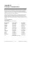
Appendix D
Customer Communication
For your convenience, this appendix contains forms to help you gather the
information necessary to help us solve technical problems you might have
as well as a form you can use to comment on the product documentation.
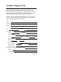
Filling out a copy of the Technical Support Form before contacting National
Instruments helps us help you better and faster.
National Instruments provides comprehensive technical assistance around
the world. In the U.S. and Canada, applications engineers are available
Monday through Friday from 8:00 a.m. to 6:00 p.m. (central time). In other
countries, contact the nearest branch office. You may fax questions to us at
any time.
Corporate Headquarters
(512) 795-8248
Technical Support fax: (512) 794-5678
Branch Offices
Australia
Austria
Belgium
Denmark
Finland
France
Germany
Italy
Japan
Netherlands
Norway
Spain
Sweden
Switzerland
U.K.
Phone Number
03 879 9422
0662 435986
02 757 00 20
45 76 26 00
90 527 2321
1 48 65 33 00
089 7 14 50 93
02 48301892
03 3788 1921
01720 45761
03 846866
91 640 0085
08 730 49 70
056 27 00 20
0635 523545
or 0800 289877 (in U.K. only)
© National Instruments Corp.
D-1
Fax Number
03 879 9179
0662 437010 19
02 757 03 11
45 76 71 11
90 502 2930
1 48 65 19 07
089 7 14 60 35
02 48301915
03 3788 1923
01720 42140
03 846860
91 640 0533
08 730 43 70
056 27 00 25
0635 523154
GPIB-232CV User Manual
Technical Support Form
Photocopy this form and update it each time you make changes to your
software or hardware, and use the completed copy of this form as a
reference for your current configuration. Completing this form accurately
before contacting National Instruments for technical support helps our
applications engineers answer your questions more efficiently.
If you are using any National Instruments hardware or software products
related to this problem, include the configuration forms from their user
manuals. Include additional pages if necessary.
Name
Company
Address
Fax (
)
Phone (
)
Computer brand
Model
Processor
Operating system
Speed
MHz
RAM
_MB
Display adapter
Mouse
yes
no
Other adapters installed
Hard disk capacity
MB
Brand
Instruments used
National Instruments hardware product model
Revision
Configuration
(continues)
National Instruments software product
Version
Configuration
The problem is
List any error messages
The following steps will reproduce the problem
GPIB-232CV Hardware and Software
Configuration Form
Record the settings and revisions of your hardware and software on the line
to the right of each item. Update this form each time you revise your
software or hardware configuration, and use this form as a reference for
your current configuration.
National Instruments Products
•
GPIB-232CV Model
•
U20 Switch Setting
•
U22 Switch Setting
Other Products
•
Operating System and Version
•
Application Programming Language
•
Other Devices in System
•
Serial Cable Wiring Diagram:
Documentation Comment Form
National Instruments encourages you to comment on the documentation
supplied with our products. This information helps us provide quality
products to meet your needs.
Title:
GPIB-232CV User Manual
Edition Date:
April 1994
Part Number:
320109-01
Please comment on the completeness, clarity, and organization of the
manual.
(continues)
If you find errors in the manual, please record the page numbers and
describe the errors.
Thank you for your help.
Name
Title
Company
Address
Phone
(
)
Mail to:
Technical Publications
National Instruments Corporation
6504 Bridge Point Parkway, MS 53-02
Austin, TX 78730-5039
Fax to:
Technical Publications
National Instruments Corporation
MS 53-02
(512) 794-5678
Glossary
Prefix
Meaning
Value
µmk
M-
micromillikilomega-
10-6
10-3
103
106
°
%
degree
percent
A
C
hex
Hz
in
KB
m
MB
oz
sec
V
VAC
VDC
amperes
Celsius
hexadecimal
hertz
inches
kilobytes of memory
meters
megabytes of memory
ounce
seconds
volts
volts alternating current
volts direct current
© National Instruments Corp.
G-1
GPIB-232CV User Manual