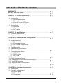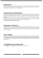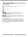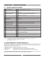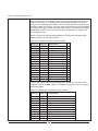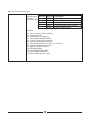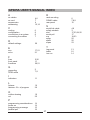
1
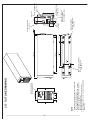
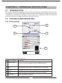
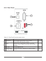
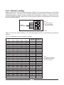
KARMIEL INDUSTRIAL ZONE, POB 500, ZC-20101, ISRAEL. TEL: 972-4-9887491 FAX: 972-4-9887487 DECLARATION OF CONFORMITY We Nemic-Lambda Ltd., located at Karmiel Industrial zone, Israel, declare under our sole responsibility that the product: Product Name: GPIB-RS485 Controller Model: GP485Arated 100-240Vac Conforms to the following product specifications: Safety: EN61010-1 :2001 (2nd Edition) Electromagnetic Emissions: EN 61326:1997A1:1998 EN 61362:1997A2:2001 EN 61326:1997A3:2003 CISPR 11:1997, Class B,A1:1999 CISPR 11:1997, Class B,A2:2002 IEC 61000-4-2 : 1995 IEC 61000-4-3 : 1995 IEC61000-4-6 : 1996 AD: 8KV, CD:4KV (80-1000 Mhz), 1V/m 80%A.M. by 1kHz (0.15-80MHz) 3VRMS, 80%A.M. by 1kHz Power and Signal lines The product herewith complies with the requirements of the Low Voltage Directive 73/23/EEC as amended by 93/68/EEC, and the EMC directive 89/336/EEC, as amended by 92/31/EEC and 93/68/EEC for Electrical Equipment used in Information Technology environments, and carries the CE mark accordingly. Our authorized representative in the EU is Coutant Lambda Limited, located at Kingsley Avenue, Ilfracombe, Devon EX34 8ES, UK. Further, all products covered by this declaration are manufactured by processes which ensure continued compliance of the products with the requirements of the Low Voltage and the EMC directives. Name ofAuthorized Signatory: Martin Southam Signature ofAuthorized Signatory: Position ofAuthorized Signatory: Director of Marketing, Coutant Lambda Date: 30/10/06 Place where signed: Ilfracombe, UK This page intentionally left blank TABLE OF CONTENTS: GP485A WARRANTY .......................................................................................... pg. 1 SAFETY INSTRUCTIONS ..................................................................... pg. 2 CHAPTER 1. General Information ...................................................... pg. 4 1.1 User’s manual content 1.2 Introduction 1.2.1 General description 1.2.2 Configurations 1.2.3 Control via the GPIB port 1.2.4 Input/output connections 1.3 Accessories 1.3.1 General 1.3.2 Serial link cable 1.3.3 AC cables CHAPTER 2. Specifications ................................................................ pg. 5 2.1 GP485A specifications 2.2 Supplemental characteristics CHAPTER 3. Installation and Configuration...................................... pg. 6 3.1 General 3.2 Initial inspection 3.2.1 Mechanical inspection 3.2.2 Preparation for use 3.2.3 AC source requirements 3.3 Cooling and placement 3.4 Rack mounting 3.5 Repackaging for shipment 3.6 Power connection............................................................................ pg. 7 3.7 Connecting the cables 3.7.1 RS485 cable 3.7.2 GPIB cable 3.7.3 AC cord 3.8 Connections in a system................................................................... pg. 8 3.9 RS485 connector pinout 3.10 Connecting GP485A to Zup power supply.......................................pg. 9 3.11 The GPIB connector 3.12 Controller default configuration 3.13 Outline drawing.............................................................................. pg. 10 CHAPTER 4. Operating Instructions................................................... pg. 11 4.1 Introduction 4.2 Controls and indicators 4.2.1 Front panel 4.2.2 Rear panel.............................................................................. pg.12 4.2.3 Top panel................................................................................ pg.13 TABLE OF CONTENTS: GP485A 4.3 Turn-on checkout procedure........................................................... pg.14 4.3.1 General 4.3.2 Prior to operation 4.3.3 Power on 4.4 Status information and error handling characteristic 4.5 Programming considerations 4.6 Programming message format....................................................... pg.15 4.6.1 Programming message example 4.6.2 How messages are processed 4.7 Function arguments 4.7.1 Abbreviations for arguments 4.8 Addressing the GP485A and serial port 4.8.1 Address of the GP485A 4.8.2 Address of the serial port...................................................... pg.16 4.8.3 Addressing the GP485A and serial device as listeners 4.8.4 Addressing the GP485A and serial device as talkers 4.9 GPIB read and write termination methods (END and EOS)........... pg.17 4.10 Serial port transmission 4.11 Operation of the GP485A as a GPIB device 4.12 Serial poll responses 4.13 Service request (SRQ)................................................................... pg.18 4.13.1 Service Request at Power On 4.13.2 SRQ* conditions 4.13.3 SRQ* generation by the GP485A 4.13.4 SRQ* generation by Zup Power Supply 4.13.5 GP485A initialize for using SRQ* 4.14 Parallel poll.................................................................................... pg.19 4.14.1 Take control (TCT) 4.14.2 Group execute trigger (GET) 4.14.3 Go to local (GTL) 4.14.4 Device clear CHAPTER 5. Functions and Commands.............................................. pg.20 5.1 Introduction 5.2 Function names 5.2.1 Default settings and related functions 5.2.2 List of functions by group 5.2.3 Alphabetical function list........................................................ pg.21 5.3 Command function syntax CHAPTER 6. Maintenance.................................................................. pg.26 6.1 Introduction 6.2 Units under warranty 6.3 Periodic maintenance 6.4 Adjustment and calibration 6.5 Part replacement and repairs 6.6 Fuse ratings 6.7 Example of program written in Labview USER’S MANUAL INDEX.................................................................... pg.27 WARRANTY This Nemic-Lambda product is warranted against defects in materials and workmanship for a period of three years from date of shipment. During the warranty period, Nemic-Lambda will, at it’s option, either repair or replace products which prove to be defective. LIMITATION OF WARRANTY The warranty shall not apply to defects resulting from improper or inadequate usage or maintenance by the buyer, buyer supplied products or interfacing. The warranty shall not apply to defects resulting from unauthorized modifications or from operation exceeding the environmental specifications of the product. Nemic-Lambda does not warrant the buyers circuitry or malfunctions of Nemic-Lambda products resulting from the buyer’s circuitry. Furthermore, Nemic-Lambda does not warrant any damage occurring as a result of the buyer’s circuitry or the buyer’s - supplied products. No other warranty is expressed or implied. WARRANTY SERVICE This product must be returned to an authorized Nemic-Lambda service facility for repairs or other warranty service. For products returned to Nemic-Lambda for warranty service, the buyer shall prepay shipping charges to Nemic-Lambda and Nemic-Lambda shall pay the shipping charges to return the product to the buyer. DISCLAIMER The information contained in this document is subject to change without notice. Nemic-Lambda shall not be liable for errors contained in this document or for incidental or consequential damages in connection with the furnishing, performance or use of this material. No part of this document may be photocopied, reproduced or translated into another language without the prior written consent of Nemic-Lambda. TRADEMARK INFORMATION Microsoft and Windows are trademarks of Microsoft Corporation. SAFETY INSTRUCTIONS CAUTION The following safety precaution must be observed during all phases of operation, service and repair of this equipment. Failure to comply with the safety precautions or warnings in this document violates safety standards of design, manufacture and intended use of this equipment and may impair the built-in protections within. Nemic-Lambda shall not be liable for user’s failure to comply with these requirements. INSTALLATION CATEGORY The GP485A Series has been evaluated to INSTALLATION CATEGORY II. Installation Category (over voltage category) II: local level, appliances, portable equipment etc.. With smaller transient over voltages than Installation Category (over voltage category) III. GROUNDING This product is a Safety Class 1 instrument. To minimize shock hazard, the instrument chassis must be connected to an electrical ground. The instrument must be connected to the AC power supply mains through a three conductor power cable, with the ground wire firmly connected to an electrical ground (safety ground) at the power outlet. For instruments designed to be hard - wired to the supply mains, the protective earth terminal must be connected to the safety electrical ground before an other connection is made. Any interruption of the protective ground conductor, or disconnection of the protective earth terminal will cause a potential shock hazard that might cause personal injury. FUSES Fuse must be changed by authorized Nemic-Lambda service personnel only. For continued protection against risk of fire, replace only with the same type and rating of fuse. Refer to maintenance instructions in chapter 6 for fuse rating. INPUT RATINGS Do not use AC supply which exceeds the input voltage and frequency rating of this instrument. The input voltage and frequency rating of the GP485A is; 100-240V~, 50/60Hz. For safety reasons, the mains supply voltage fluctuations should not exceed +/- 10% of nominal voltage. LIVE CIRCUITS Operating personnel must not remove the instrument cover. No internal adjustment or component replacement is allowed by non-Nemic-Lambda qualified service personnel. Never replace components with power cable connected. To avoid injuries, always disconnect power, discharge circuits and remove external voltage sources before touching components. PART SUBSTITUTIONS AND MODIFICATIONS Part substitutions and modifications are allowed by authorized Nemic-Lambda service personnel only. For repairs or modifications, the instrument must be returned to a Nemic-Lambda service facility. ENVIRONMENTAL CONDITIONS The GP485A series safety approval applies to the following operating conditions: * Indoor use * Ambient temperature: 0OC to 50OC * Maximum relative humidity: 90% (no dew drop) * Altitude: up to 3,000 m * Pollution degree 2 SAFETY INSTRUCTIONS SAFETY SYMBOLS ! Instruction manual symbol. The instrument will be marked with this symbol when it is necessary for the user to refer to the instruction manual. Indicates hazardous voltage. Indicates ground terminal. WARNING The WARNING sign denotes a hazard. An attention to a procedure is called. Not following procedure correctly could result in personal injury. A WARNING sign should not be skipped and all indicated conditions must be fully understood and met. CAUTION The CAUTION sign denotes a hazard. An attention to a procedure is called. Not following procedure correctly could result in damage to the equipment. Do not proceed beyond a CAUTION sign until all indicated conditions are fully understood and met. FCC COMPLIANCE NOTICE: Note: This equipment has been tested and found to comply with the limits for a Class A digital device, pursuant to part 15 of the FCC Rules. These limits are designed to provide reasonable protection against harmful interference when the equipment is operated in a commercial environment. This equipment generates uses, and can radiate radio frequency energy and, if not installed and used in accordance with the instruction manual, may cause harmful interference to radio communications. Operation of this equipment in a residential area is likely to cause harmful interference in which case the user will be required to correct the interference at his own expense. CHAPTER 1 GENERAL INFORMATION 1.1 USER’S MANUAL CONTENT This user’s manual contains the operating instructions, installation instructions and specifications of the GP485A. For information related to operation with the Zup Series, refer to Nemic-Lambda’s Zup User’s Manual. 1.2 INTRODUCTION 1.2.1 General description The GP485A is a high performance GPIB-to-RS485 interface. It enables a computer with a GPIB port to communicate with up to 31 Zup power supplies via a single GP485A unit. The GP485A has all the software and logic required to implement the physical and electrical specifications of the IEEE488 and RS485 standards. 1.2.2 Configurations The GP485A can be configured into a GPIB system of up to 14 controllers. Each controller can control up to 31 Zup units in dual GPIB addresses. One address to configure itself and one to communicate with the Zup units. 1.2.3 Control via the GPIB port The following parameters can be programmed via the GPIB communication port: 1. GP485A configuration 2. Zup parameters ( refer to Zup User’s Manual Par. 1.2.3 ) 1.2.4 Input/Output connections Connections of AC source, GPIB port and RS485 port are made to rear panel connectors. AC input: IEC inlet GPIB port: Standard 24 pin shielded champ female connector RS485 port: RJ-45, shielded connector 1.3 ACCESSORIES 1.3.1 General Accessories are delivered with the GP485A upon ordering. Below are listed possible accessories and ordering numbers: ORDER# DESCRIPTION NL100 19” rack, 3U height NL101 Blank panel for 19” rack NL103 Additional User’s Manual 1.3.2 Serial link cable Serial link cable for linking the GP485A to the Zup units via RS485 communication is provided with each GP485. Cable description: 0.5m typ. length, shielded, RJ-45 type plugs, 8 contacts. 1.3.3 AC Cables PART No. MARKET NC301 USA NC302 NC303 DESCRIPTION 15A, 125V, unshielded, 2m typ. length, with IEC320 connector on one side and NEMA-5-15P connector on the other side. EUROPE 10A, 250V, unshielded, 2m typ. length, with IEC320 connector on one side and INT’L standard VII, dual earthing on the other side. GENERAL 10A, 250V, unshielded, 2m typ. length, with IEC320 connector on one side and unterminated striped wires on the other side. Use the cable only with plug approved by the national safety standards of the country of usage. CHAPTER 2 SPECIFICATIONS 2.1 GP485A SPECIFICATIONS 1 Input Voltage / freq. (*1) 2 Input Current 100/200Vac - 85~265Vac continuous, 47~63Hz - Less than 0.14A at 100V, 0.07A at 200V 3 Inrush Current 100/200Vac (*2) A 15 / 30 4 IEEE488 capability - SH1, AH1, T6, TE0, L4, LE0, SR1, RL0, PP1, 6 Indications - LED’s: Power / Ready, Talk, Listen, SRQ DC1, DT0, C0, E1, E2 7 Operating temp. O C 0~50 8 Storage temp. O C - 20 ~70 9 Operating humidity - 30~90% RH, no dew drop 10 Storage humidity - 10~90% RH, no dew drop 11 Conducted emission - EN55022B, VCCI-B , FCC part 15 (class B) - EN55022B, VCCI-B , FCC part 15 (class B) 12 Radiated emmision 13 Weight Kg 1.95 14 Size (W*H*D) mm 70x124x350 15 Applicable safety standards - UL61010-1, EN61010-1 16 Applicable EMC standards - EN61326-1, IEC61326-1 17 Withstand voltage - Input-Output: 3KVac, Input-Chassis: 1.5KVac Output-Chassis: 500Vac 18 Leakage current mA Less than 1mA 19 Vibration (with mounting screws) G 1~55Hz, Amp. (sweep 1 min) less than 2G, X, Y, Z 1hour each 20 Shock G Less than 20 Notes: * 1: For cases where conformance to various safety specs (UL, IEC etc.) are required, to be described as 100-240VAC, 50/60Hz on name plate. * 2: At cold start. Ta = 25OC. 2.2 SUPPLEMENTAL CHARACTERISTICS The supplemental characteristics give typical but non-warranted performance characteristics. The supplemental characteristics are useful in accessing applications for the GPIB controller. Types of supplemental characteristics are listed below. 1. RELIABILITY DATA: Reliability performance of the controller. 2. EN61000 DATA: Performance of the controller under EN61000 test conditions. 3. EMI DATA: Typical EMI ( Conducted and Radiated ) performance of the controller. The supplemetal characteristics data are held in each Nemic-Lambda sales and service facility. For further details, please contact the Nemic-Lambda representative nearest you. CHAPTER 3 INSTALLATION AND CONFIGURATION 3.1 GENERAL This chapter contains instructions for initial inspection, preparation for use and repackaging for shipment. Connection to PC and Zup power supplies is described in Par. 3.7 ~ 3.11. NOTE GP485 generates a magnetic field which might affect the operation of other instruments. If your equipment is susceptible to magnetic fields, do not position adjacent to the GP485. 3.2 INITIAL INSPECTION Prior to shipment the GP485A was inspected and found free of mechanical or electrical defects. Upon unpacking of the GP485A, inspect for any damage which may have occurred in transit. Keep all packing materials until inspection has been completed. If any damage is detected, file a claim with the carrier immediately and notify the Nemic-Lambda sales or service facility nearest you. 3.2.1 Mechanical inspection The mechanical inspection should confirm that there is no exterior damage to the GP485A such as broken connectors and front panel are not scratched or cracked. 3.2.2 Preparation for use In order to be operational, the GP485A must be connected to an appropriate AC source. The line voltage must be within the GP485A specification. DO NOT apply power before reading paragraph 3.2.3 3.2.3 AC Source requirements The GP485A can be operated from a nominal 100V to 240V, single phase, 47 ~ 63Hz. The input voltage range and current required is specified in chapter 2. Make sure that the AC voltage does not fall below “low limit” specifications. 3.3 COOLING AND PLACEMENT O The GP485A should be used in an area where the ambient temperature does not exceed +50 C. Do not install the GP485A adjacent to a hot surface or heat generating equipment. 3.4 RACK MOUNTING GP485A can be mounted in a standard 19” rack (3U height) and occupy 1/6 rack length. The GP485A should be fixed by M4 screws replacing the rubber feet on the bottom of the GP485A. Screws must not protrude more than 6mm into the unit. Refer to the outline drawing in this chapter for mounting details. 3.5 REPACKAGING FOR SHIPMENT To ensure safe transportation of the instrument, it is recommended to use the original package. The original packaging material is reusable. If the original package is not available, contact the NemicLambda Sales or service facility near you for details on obtaining suitable packaging and shipping information. Please attach a tag to the GP485A unit describing the problem and specifying the owner, model number and serial number of the unit. 3.6 POWER CONNECTION CAUTION Connection of the GP485A to an AC source should be made by an electrician or other qualified personnel. The GP485A is equipped with a three conductor power cable. The third conductor is the ground conductor. When the cable is plugged-in to an appropriate receptacle, the GP485A is grounded. Under no circumstances should the GP485A be operated without an adequate ground connection. If a two contact receptacle is encountered, it must be replaced by a three contact receptacle, properly grounded. This operation should be done by a qualified electrician. It is recommended to keep the AC input wires separate from the communication cables to avoid interference. WARNING Some components inside the GP485A are at AC voltage even when the On/Off switch is in the “Off” position. To avoid the hazard of electric shock, disconnect line cord and wait 2 minutes before removing cover. 3.7 CONNECTING THE CABLES WARNING Turn off the AC input power before making or changing any rear panel connection. Make sure that all connections are securely tightened before applying power. 3.7.1 RS485 cable Connect one end of the serial communication cable to the RS485 OUT connector located on the GP485 rear panel. Connect the other end of the cable to the Zup power supply RS485/232 IN connector. Be sure to use only shielded cable, and follow the RS485 cabling restrictions. 3.7.2 GPIB cable Connect one end of the GPIB cable to the GPIB connector located on the GP485A rear panel and tighten the thumb screws on the connector. Connect the other end to the GPIB connector on the GPIB controller. Shielded or non-shielded GPIB cable may be used. When non-shielded cable is used, an EMI suppressor clamp should be attached to the cable, as close as possible to the GP485A (The EMI suppressor is included in the package). 3.7.3 AC cord Connect the AC cord to the GP485 ac input connector located on the rear panel, then connect the plug to an ac outlet of the correct voltage as specified in the specifications in chapter 2. To meet radiated EMI specification, the EMI suppressor clamp should be attached to the AC cable as close as possible to the AC inlet of the power supply. 3.8 CONNECTIONS IN A SYSTEM RS-485 RS-485 GPIB BUS GP485 ( 1 ) ZUP ( 1 ) RS-485 GP485 ( 2 ) ZUP (31) RS-485 ZUP ( 1 ) RS-485 GP485 (14 ) ZUP (31) RS-485 ZUP ( 1 ) ZUP (31) * Controls up to 31 ZUP units through a single GPIB address. * Conforms to all versions of the IEEE488 * 19” racking possibility. Fig. 3-1: System connections 3.9 RS485 CONNECTOR PINOUT 8 7 6 5 4 3 2 1 TXD + _ NC TXD + SG RXD _ NC RXD Not used Shield (connector enclosure) Fig. 3-2: The RS485 connector pinout (view of GP485A rear panel) 3.10 CONNECTING GP485A TO ZUP POWER SUPPLY Fig.3-3: GP485A to ZUP cable layout 1 8 1 8 RS485/232 IN RS485 OUT 8 7 6 5 4 3 2 1 SG _ TXD + TXD _ RXD + RXD 5 2 4 6 8 SHIELD GP485A (rear panel view) SHIELD IN OUT REMARKS 5 5 SG 2 2 TXD - Twisted 4 4 TXD + Pair 6 6 RXD - Twisted 8 8 RXD + Pair + RXD TX (RS232) _ RXD SG + TXD 8 7 6 5 4 3 2 1 5 SG _ 2 TXD + 4 TXD_ 6 RXD + 8 RXD RX (RS232) _ TXD Not Used Zup Unit (rear panel view) Fig.3-4: Connecting GP485A to Zup power supply via RS485 cable. 3.11 THE GPIB CONNECTOR The GPIB connector is a standard 24-pin shielded Champ female connector with metric screwlock hardware. Fig. 3-5 shows a diagram of the GPIB connector and the signals supported. The * suffix indicates that the signal is active low. 13 14 15 16 17 18 19 20 21 22 23 24 DIO5 * DIO6 * DIO7 * DIO8 * REN * GND ( Twisted Pair with DAV * ) GND ( Twisted Pair with NRFD * ) GND ( Twisted Pair with NDAC * ) GND ( Twisted Pair with IFC * ) GND ( Twisted Pair with SRQ * ) GND ( Twisted Pair with ATN * ) SIGNAL GROUND 3.12 CONTROLLER DEFAULT CONFIGURATION The GP485A power-up default setting is as follows: GPIB address ( the GP485A is shipped from Factory with address “1”) 8 data bits/character 1 stop bit/character no parity 9600 baud rate 1 2 3 4 5 6 7 8 9 OFF 1 2 3 4 5 6 7 8 9 10 11 12 ON Fig. 3-5: The GPIB Connector and Signal Designations DIO1 * DIO2 * DIO3 * DIO4 * EOI * DAV * NRFD * NDAC * IFC * SRQ * ATN * SHIELD If you want to change any default settings, you must change the DIP switch settings or set it by software. To change the DIP switch, shut down the system and then refer to Par. 4.2.3. To change the serial port setting refer to table 5-5 , sps command. POWER/ READY 48.0+1.0 SRQ LISTEN TALK 70+0.5 1. MOUNTING SCREWS MUST NOT PROTRUDE INTO THE CHASSIS MORE THAN 6mm. 2. GPIB CONNECTOR: SHIELDED 24-PIN , FEMALE, RIGHT ANGLE CONNECTOR (AMP P/N: 5554932-1 REVERSE ORIENTATION). 3. STANDOFF STUD, METRIC, AMP P/N: 554808-1. 4. RS485 CONNECTOR: RJ-45 , 8 CONTACTS SHIELDED CONNECTOR. NOTE : 11.0 124.0+0.5 MODEL NAME WILL BE SHOWN HERE. 131.0+0.5 A B 48.4+0.5 MOUNTING HOLES TAP M4 4 PLACES MARKED “A” (see note 1) A B 201.5+0.5 290.0+1.0 350.0+1.0 A A B B 59.5 20.0 ADDRESS SETTING DIP SWITCH INPUT VOLTAGE AND CURRENT RATING WILL BE SHOWN HERE 21.00.5 IEC320 AC INLET GPIB CONNECTOR (see note 2) (see note 3) 50.0 16.8 RUBBER BUMPERS 4 PLACES MARKED “B” (removable) 6.80.5 RS485 CONNECTOR (see note 4) 77.30.5 3.13 OUTLINE DRAWING 10.6 30.00.5 80.7 CHAPTER 4 OPERATING INSTRUCTIONS 4.1 INTRODUCTION This chapter describes the operating modes, controls and indicators of the GP485A controller. It also describes how to program the GP485A controller, status and error handling information, programming considerations, programming messages, function arguments, addressing, GPIB read and write termination methods, serial port transmissions and mode functions. 4.2 CONTROLS AND INDICATORS 4.2.1 Front panel 3 2 4 1 5 Fig. 4-1: Front panel controls and indicators Table 4-1: Front panel controls and indicators # Control/Indicator Indication 1 Power/Ready Indicates that the power is “ON” . The unit is ready to operate once the LED illuminates. 2 Talk Indicates that the GP485A is addressed as a GPIB Talker. 3 Listen Indicates that the GP485A is addressed as a GPIB Listener. 4 SRQ Indicates that the GP485A signal line SRQ is asserted. 5 AC ON/OFF Turns AC power On and Off. 4.2.2 Rear Panel GPIB RS485 OUT 2 1 123456789 ADDR AC INPUT 100-240V ~0.14A 56/60Hz 3 4 Fig. 4-2: Rear Panel Connections Table 4-2: Rear Panel Connections and controls # Connector Description Par. 1 RS485 OUT JR-45 shielded type connector, used for RS485 communication with Zup power supplies. 3.9 , 3.10 2 GPIB Shielded 24-pin Champ female connector, with metric screwlock. Used for GPIB communication with the GPIB controller. 3.8 , 3.11 3 AC Input IEC type appliance inlet. 3.2.3 4 Address select DIP switch 9 Position DIP switch. Positions 4 to 8 used for address selection. 4.2.3 4.2.3 Address setting Switches 8 through 4 set the GPIB address of the GP485A. The serial device address is the GP485A GPIB address plus 1, refer also to par. 4.8. Before setting the address switches, find two consecutive addresses that are not used by any other GPIB devices in the system. In Figure 4-2, switches 8 to 4 are ON, OFF, ON, OFF and OFF respectively, indicating that the GP485 is at GPIB address 5 and the serial device is at GPIB address 6. ON 8 7 6 5 4 GPIB ADDRESS Note: DIP switch position 1, 2, 3, 9 should be in right position (Off). Figure 4-2: sample of address setting (Rear panel view) Table 4-3 shows the switch settings for the GP485A address and the corresponding serial device address. Table 4-3: GPIB address switch settings for GP485A 8 ON OFF ON OFF ON OFF ON OFF ON OFF ON OFF ON OFF ON OFF ON OFF ON OFF ON OFF ON OFF ON OFF ON OFF ON OFF 7 OFF ON ON OFF OFF ON ON OFF OFF ON ON OFF OFF ON ON OFF OFF ON ON OFF OFF ON ON OFF OFF ON ON OFF OFF ON Switches 6 OFF OFF OFF ON ON ON ON OFF OFF OFF OFF ON ON ON ON OFF OFF OFF OFF ON ON ON ON OFF OFF OFF OFF ON ON ON 5 OFF OFF OFF OFF OFF OFF OFF ON ON ON ON ON ON ON ON OFF OFF OFF OFF OFF OFF OFF OFF ON ON ON ON ON ON ON 4 OFF OFF OFF OFF OFF OFF OFF OFF OFF OFF OFF OFF OFF OFF OFF ON ON ON ON ON ON ON ON ON ON ON ON ON ON ON GP485A Serial Port Address Address 1 2 3 4 5 6 7 8 9 10 11 12 13 14 15 16 17 18 19 20 21 22 23 24 25 26 27 28 29 30 2 3 4 5 6 7 8 9 10 11 12 13 14 15 16 17 18 19 20 21 22 23 24 25 26 27 28 29 30 0 Note: To change the address, the GP485A AC power must be turned Off. 4.3 TURN-ON CHECKOUT PROCEDURE 4.3.1 General The following procedure ensures that the GP485A controller is operational and may be used as a basic incoming inspection check. 4.3.2 Prior to operation Check that the rear panel RS485 cable is connected as shown in Fig. 3-3. Connect the GPIB cable between the GP485A and the host computer. (Refer to Fig. 3-4 for GPIB connector description). Connect the GP485A to an AC source as described in paragraph 3.6. 4.3.3 Power on Turn on the GP485A. Wait until the Power/Ready led illuminates. Set the baud rate to same as the Z.UP power supply (see table 5-5 , spset) 4.4 STATUS INFORMATION AND ERROR HANDLING CHARACTERISTIC The functions description in Table 5-5 explains that the GP485A records specific status and error information. This means that it stores that information in it’s memory so that it is available when requested by the user. The functions description also include an explanation on return of information to the user from the GP485A. This is accomplished by information sent to the user from the GP485A over the GPIB. The GP485A continuously monitors the serial port for transmission errors. If an error is encountered in the serial data, the GP485A records the error. The GP485A can be programmed to ignore serial port errors using the spign function. 4.5 PROGRAMMING CONSIDERATIONS - The program examples within the functions description are written in Microsoft QuickBASIC Version 4.5, using National Instruments NI-488.2 function calls. Although the examples in this manual are written in BASIC. The GP485A can be programmed using any language that has access to a GPIB port. - The following NI-488.2 function call addresses the GP485A to listen and sends it the programming message spset, followed by a carriage return. WRT$=”SPSET”+CHR$(13) CALL IBWRT(GP485A% , WRT$) If not using the National Instruments NI-488.2 software, be sure your program properly addresses the GP485A and the serial device when writing to and reading from them. - In the function syntax descriptions, arguments shown in square brackets ( [ ] ) are optional. Do not enter the brackets as part of the argument. - Function name abbreviations can be used, which include as many characters as necessary to distinguish them from other functions. The abbreviated forms are indicated by bold text in the syntax description of each function. 4.6 PROGRAMMING MESSAGE FORMAT You can program the GP485A by sending it programming messages, which are ASCII strings, via it’s GPIB port. Each programming message is terminated with a carriage return (<CR>), a linefeed (<LF>), or a carriage return followed by a linefeed (<CR><LF>). This is denoted by <CR> in the syntax portions of the function descriptions and by CHR$(13) in the BASIC examples. Programming messages can be entered in any combination of uppercase and lowercase letters. 4.6.1 Programming message example The following lines of code are an example of a programming message in BASIC: WRT$ =”eos x,b,10”+CHR$(13) CALL IBWRT(GP485A% , WRT$) The programming message WRT$ contains eos, which is the function name, x and 10 are the arguments, and CHR$ is the terminating carriage return. This programming message tells the GP485A to assert the EOI* line when it sends the end-of-string character linefeed. The second line of the example is a NI-488.2 function call that allows a personal computer to control the GPIB from Microsoft BASIC. This function outputs the string in WRT$ to the GP485A. 4.6.2 How messages are processed The GP485A processes each programming message on a line-by-line basis. When the GP485A receives a message, it buffers the message, interprets the function name and arguments, then executes the message. 4.7 FUNCTION ARGUMENTS When typing in a function, separate the first argument from the function name with at least one space. Separate each additional argument with at least one space or a comma. In the syntax portions of the function descriptions in Table 5-5, the square brackets ([ ]) that enclosed some arguments indicate that those arguments are optional. Do not enter the brackets as part of the argument. 4.7.1 Abbreviations for arguments The term bool is an abbreviation used for an argument in the functions description. The values for bool are: 1 = true, on or enable 0 = false, off or disable 4.8 ADDRESSING THE GP485A AND SERIAL PORT The GP485A uses dual addressing to determine what type of GPIB data is being processed. With dual addressing, the GP485A recognizes two different GPIB addresses. The first address is the GP485A address. When the GP485A receives it’s own address, the data received is referred to as programming messages; the data it sends is referred to as status information. The second address is the serial port address. When the GP485A receives the serial port address, the data it sends and receives is referred to as serial data. 4.8.1 Address of the GP485A The address of the GP485A is the primary address set with the DIP switch on the rear panel. Par. 4.2.3, with the secondary addressing disabled. 4.8.2 Address of the serial port The address of the serial port is the GP485A address plus 1, with the secondary addressing disabled. However, if primary address of 30 with the configuration switch is selected, the serial port is at 0. The primary address is set with the DIP switch on the rear panel, refer to Par. 4.2.3. 4.8.3 Addressing the GP485A and serial device as listeners When the GP485A receives it’s own listen address, it examines the data received over the GPIB, treats it as a programming message, and takes action based on that data. When the GP485A receives the serial device listen address, it forwards the data over the GPIB to the serial port without examining or modifying the data. For example: to send a command from user’s computer over the GPIB to the power supply. Before sending the command to the serial port, the GP485A must be configured to the suitable serial port parameters. Follow these steps to send a command from a computer to a Zup power supply connected to the serial port : 1. Address the GP485A to listen by sending it’s listen address. 2. Send the programming message “sps 9600 n 8 1 “ to the GP485A. The GP485A interprets this programming message and acts upon it without sending any data on to the serial device. 3. Address the serial port to listen by sending the serial device listen address to the GP485A. 4. Send the command over the GPIB. The GP485A sends the command to the power supply without examining it for meaning. The LISTEN LED on the GP485A is lit when either the GP485A or the serial device is addressed to 4.8.4 Addressing the GP485A and serial device as talkers When the GP485A receives it’s own talk address, it sends out status information. When the GP485A receives the serial device talk address, it sends data out to the GPIB that it has received from the serial device. For example: User requests power supply to return status information. Follow the following steps to retrieve the data: 1. Address the serial power supply to talk by sending the serial device talk address to the GP485A. If the GP485A receives the serial device talk address, but has no data in it’s serial port receive buffer to send it waits for data from the serial power supply to fill the request. 2. Perform a GPIB read of 100 bytes. The GP485A retrieves 100 bytes from it’s serial port receive buffer and sends them to the user. 3. Find out if the serial power supply has sent more bytes to the GP485A by asking the GP485A to send status information. a. Send the GP485A it’s listen address. b. Send the programming message stat n to the GP485A. c. Send the GP485A it’s talk address. d. Perform a GPIB read of 20 bytes. The GP485A sends it’s status information, terminated by the GPIB END message. If the GP485A receives it’s talk address but has nothing to send, it responds to GPIB reads with a carriage return and a linefeed, accompanied by END. The status information returned contains the number of bytes remaining in the serial port receive buffer. This information helps the user to decide how much data to continue to collect from the serial device. The TALK LED on the GP485A is lit when either the GP485A or the serial power supply is addressed to talk. 4.9 GPIB READ AND WRITE TERMINATION METHODS (END and EOS) The IEEE 488 specification defines two ways that GPIB Talkers and Listeners can identify the last byte of data messages: END and EOS. The two methods permit a Talker to send data massages of any length without the Listener(s) knowing the number of transmission bytes in advance. END and EOS can be used individually or in combination, but the Listener must be configured to detect the end of transmission. END message: The Talker asserts the EOI* (End or Identify) signal while the last data byte is being transmitted. The Listener stops reading when it detects a data byte accompanied by EOI*, regardless of the value of the byte. EOS character: The Talker transmits an EOS (end-of-string) character at the end of it’s data string. The Listener stops receiving data when it detects the EOS character. Either a 7-bit ASCII character or a full 8-bit binary byte can be used. When the GP485A receives it’s own talk or listen address, no EOS modes are in effect. When talking, the GP485A asserts EOI* with the last byte of it’s response. When the GP485A receives the serial device talk address, the EOS modes in effect are those that the user selects using the eos function. 4.10 SERIAL PORT TRANSMISSION The GP485A checks the data received from the serial device for errors while it buffers data. If a serial port error occurs, The GP485A records the appropriate error code. There are two ways to determine if a serial port error has occurred: * Use the stat function to request the GP485A status information. After the serial error code has been reported, it is automatically cleared and no further action to the GP485A is necessary. * Serial poll the GP485A and check the serial poll response byte to see if it’s SERR bit is set. Refer to Par. 4.12 later in this chapter. Program the GP485A to ignore serial port errors using the spign function. 4.11 OPERATION OF THE GP485A AS A GPIB DEVICE The GP485A operates like any other GPIB device and, as such, is configured to respond in certain ways to GPIB commands. 4.12 SERIAL POLL RESPONSES When serial polled, the GP485A returns status information to the GPIB controller through the serial poll response byte. The GP485A maintains this status byte throughout operation, regardless of the srqen configuration. Table 4-4 lists the meaning of each bit in the serial poll response byte. Table 4-4: Serial port response byte Bit 0 1 2 3 4 5 6 7 Mnemonic BF GERR SERR BNE EOS RQS - Meaning Not used Serial port receive buffer is full and serial device not addressed to talk. GPIB error - see stat Table 5-5 Serial error - see stat Table 5-5 Serial port receive buffer not empty and serial device not addressed to talk. EOS character received and serial device not addressed to talk. Request service (SRQ* asserted) Not used 4.13 SERVICE REQUEST (SRQ) 4.13.1Service Request at Power On After Power On , the GP485A defaults to never asserting service request. Using the srqen function , the GP485A can be programmed to assert SRQ* under a variety of cases. 4.13.2 SRQ* conditions The GP485A will assert SRQ* in a variety of cases related to the operation of the GP485A itself and also to the operation of the Zup units connected to the GP485A serial port. 4.13.3 SRQ* generation by the GP485A The GP485A will assert SRQ* under any of the following circumstances : 1. When a GPIB error occurs , that is EARG , ECMD or ECAP as reported by stat. 2. When a serial port error occurs , that is , EPAR , EORN , EOFL or EFMR as reported by stat. 3. When the serial device is not addressed as a talker and sends a message to the GP485A. 4.13.4 SRQ* generation by Zup Power Supply A Zup Power Supply will send a string message in the event of Foldback Protection activation, Over Voltage Protection or Over Temperature Protection .For more details about the SRQ commands and queries , refer to Zup User’s Manual. The Zup Power Supply will send the message when it is not addressed as a talker and thus will cause the GP485A to assert SRQ*. The message consists of three characters and terminated with <CR><LF>. The first character identifies the SRQ cause : 1-Foldback, 2-OVP, 3-OTP. The 2nd and 3rd characters identify the Power Supply address. The Zup Power Supply will be not addressed as a talker if the last command is operational command or DCL. Example : String generated by a Zup unit : 120<CR><LF> , means foldback protection was activated in power supply address 20. The SRQ* can be identified by serial or parallel poll. Refer to par. 4.12 and 4.14 for details. If using serial Table 4-5: serial poll response. Mnemonic Description Bit Decimal 4 16 BNE Serial port receive buffer not empty and serial device not addressed to talk. 5 32 EOS EOS character received and serial device not addressed to talk. 6 64 RQS Request service (SRQ*) asserted. 4.13.5 GP485A initialize for using SRQ* WRT$= “srq 16”+CHR$(13) CALL IBWRT(GP485A%, WRT$) ‘enable to assert SRQ* if the GP485A serial buffer not empty ‘and the serial device not addressed to talk 4.14 PARALLEL POLL The GP485A sets the ist (individual status) bit whenever it asserts SRQ* and clears ist whenever it unasserts SRQ*. The GP485A implements IEEE 488 Parallel Poll (PP) interface function subset PP1. This means it cannot configure itself to respond to parallel polls. It must be configured remotely by an external Controller. 4.14.1 Take Control (TCT) This command has no effect on the GP485A. It would not make sense for control to pass to the GP485A, since all programming messages and GPIB commands must be sent to it from another GPIB device. 4.14.2 Group Execute Trigger (GET) This command has no effect on the GP485A. 4.14.3 Go To Local (GTL) This command has no effect on the GP485A. 4.14.4 Device Clear When the GP485A receives the universal Device Clear (DCL) command or when it receives It’s listen address and the Selected Device Clear (SDC) command, it clears both it’s status buffer and it’s serial port receive buffer. It also resets the GPIB serial poll response byte to zero and unasserts SRQ*. CHAPTER 5 FUNCTIONS AND COMMANDS 5.1 INTRODUCTION This chapter contains descriptions of the mode functions that can be used to program the GP485. These functions are in alphabetical order for easy reference, order by group and explanations how to use. 5.2 FUNCTION NAMES The function names have been selected to indicate the purpose of each function, thereby making programs easy to understand. However, if user’s prefer to reduce some overhead in the program and do not mind giving up these advantages, use only as much of the function name as is necessary to distinguish it from other functions. This abbreviated form of the function name is shown in bold text in the function tables and in the syntax portions of the function descriptions. 5.2.1 Default settings and related functions Tables 5-1 and 5-2, list power-on characteristics of the GP485A and the functions that can be used to change those characteristics. Table 5-1: Serial Port Characteristics Characteristic Echo bytes to serial port Enable serial port communication Baud rate Parity Bits Stop bits Send XON/XOFF Recognize XON/XOFF Report serial errors Table 5-2: GPIB Characteristics Characteristic End-of-string modes Allow GP485A to assert SRQ Power-on value No Yes 9600 None 8 1 No No No Related function echo onl spset spset spset spset xon xon spign Power-on value Related function X,B,10 eos No srqen 5.2.2 List of functions by group The GP485A functions are divided into three groups: GPIB functions, serial port functions and general use functions. These groups are defined in Table 5-3. Table 5-3: Functions by group General functions onl stat id *IDN? GPIB functions eos srqen Serial port functions echo spset xon spign 5.2.3 Alphabetical function list Table 5-4 separates the function in alphabetical order. Table 5-4: Alphabetical function list echo on/off eos modes, eoschar onl on/off spign on/off spset modes srqen mask stat options xon modes id or *IDN? 5.3 Echo characters received from serial port Change or disable GPIB end-of-string termination mode Place the GP485A serial port online/offline Ignore serial port errors Change serial port parameters Set conditions for asserting SRQ Return GP485A status Change serial port Xon/Xoff protocol Identify system COMMAND FUNCTION SYNTAX id<CR> or *IDN?<CR> echo [bool]<CR> For id, the identification message is returned in three strings. The first string identifies the software name. The second string identifies the revision level. The third string identifies the company. For the *IDN?, the identification message is returned in one string. Table 5-5: functions syntax Example: “GPIB485A, Rev0.1, Lambda” Use in a debugging environment, when a terminal is connected to the GP485A instead of serial device. Data that the GP485A would send to the power-supply is displayed on the terminal screen. User can also write characters on the terminal to send to the GP485A. bool= 0 echo off 1 echo on * call echo without argument, returns it’s current status. * echo is disabled by default. * echo remains in effect until echo called again, call onl or turn off the GP485A. Example: 1. WRT$=”echo 1”+CHR$(13) ‘Enable character CALL IBWRT(GP485A%, WRT$) ‘echoing 2. WRT$=”echo”+CHR$(13) ‘What is the current status? CALL IBWRT(GP485A%, WRT$) ‘RESP$ contains 1<CR><LF> CALL IBRD(GP485A%, RESP$) eos [X[B]eoschar]<CR> Use eos to enable the GP485A to assert EOI* and add GPIB END message to the data string sent by the serial device when the string contains the specified end-of-string character. eos applies only when the GP485A has received the serial power-supply talk address and is sending serial data to the GPIB. X,B - set EOI* with eos (XEOS) and compare all 8 bits of EOS bytes (BIN) when sending data from the power-supply. D - EOS mode disable. * EOS mode is enabled by default. * call eos without an argument returns it’s current status. * The assignment made by this function remains in effect until eos called again, call onl or turn off the GP485A. Example: 1. WRT$=”EOS X,B,10”+CHR$(13) ‘send EOI with <CR> CALL IBWRT(GP485A%, WRT$) ‘compare 8 bit 2. WRT$=”eos”+CHR$(13) ‘What is the current status? CALL IBWRT(GP485A%, WRT$) CALL IBRD(GP485A%, RESP$) ‘RESP$ contains ‘X,B,10<CR><LF> Note: The Zup power supply series default termination is <LF> therefore Example1 should be performed at each power-on of the GP485A. Table 5-5: functions syntax contd. onl [bool]<CR> Use onl to disable communications between GP485A and serial port or to reset the GP485A characteristic to it’s default values. Placing the GP485A offline is like disconnecting it’s serial cable from the serial device. bool= 0 offline 1 online * GP485A is online by default * Call onl without an argument returns it’s current status Example: 1. WRT$=”onl 1”+CHR$(13) ‘Puts GP485A online CALL IBWRT(GP485A%, WRT$) ‘and restores power-up values 2. WRT$=”ONL 0”+CHR$(13) ‘Puts GP485A offline CALL IBWRT(GP485A%, WRT$) spign [bool]<CR> Use to ignore or not ignore the occurrence of serial port errors. If not to ignore the GP485A does not store characters that contain serial errors. Also, the error is indicated in the serial error code that is returned by the stat function. If to ignore, the GP485A stores serial port errors in the buffer which are later sent out of the GPIB port when the serial device is talk addressed. No error serial code is reported by stat function. By default, the GP485A ignores serial port errors. The serial port errors include parity, overrun, framing and overflow errors. bool= 0 don’t ignore serial port errors 1 ignore serial port errors * Call spign without an argument, the GP485A returns the current seting. * spign remains in effect until spign called again, call onl or turn off GP485A. Example: 1. WRT$=”spign 0”+CHR$(13) ‘Do not ignore CALL IBWRT(GP485A%,WRT$) ‘Serial port errors 2. WRT$=”spign 1”+CHR$(13) ‘Ignore serial port CALL IBWRT(GP485A%, WRT$) ‘errors spset [baud] [parity] [databits] [stopbits]<CR> Use spset at the beginning of the program to set the GP485A serial port characteristics (baud rate, parity, data bits and stop bits) to match the Zup power supply. Possible values: baud [bits/s]: parity: data bits [b/c]: stop bits: 300, 600, 1200, 2400, 4800, 9600 n = none, e = even, o = odd 7,8 1,2 * default values: 9600 n 8 1. * spset without an argument returns it’s current serial port configuration. * spset remains in effect until spset is called again, call onl or turn off GP485A. Example: 1. WRT$=”spset 1200 n 8 1” +CHR$(13) CALL IBWRT(GP485A%,WRT$) 2. WRT$=”spset”+CHR$(13) CALL IBWRT(GP485A%, WRT$) CALL IBRD(GP485A%,RESP$) ‘Set the serial port use 1200b/s, ‘no parity, 8 data bits and 1 stop bit. ‘What are current serial ‘port settings ‘RESP$ will contain ‘1200 n 8 1<CR><LF> Note: The Zup power supply series data format is no parity, 8 data bits and one stop bit, therefore the user needs to set only the baud rate. Table 5-5: functions syntax contd. srqen [mask]<CR> Use srqen to allow the GP485A to assert SRQ* under the conditions described in Table 5-5-1. mask= 0 never assert SRQ* >0 assert SRQ* according to Table 5-5-1 Table 5-5-1: SRQ mask bits Hex Decimal Bit Value Value Mnemonic Description 1 1 0 Not used Serial port receive buffer full and serial 2 2 1 BF device not addressed to talk 2 3 4 8 4 8 GERR SERR 4 10 16 BNE 5 20 32 EOS 6 7 40 80 64 128 - GPIB error - (see stat) Serial error - (see stat) Serial port receive buffer not empty and serial device not addressed to talk EOS character received and serial device not addressed to talk Not used Not used To determine the mask value, add up the hex or decimal values of each condition of which SRQ* is to be asserted. Example: for asserting SRQ* on GPIB errors and serial port errors mask=12 ( 4 for GERR and 8 for SERR ). * srqen mode is disabled by default - SRQ* never asserted. * call srqen without an argument returns a decimal string that indicates the current setting. * srqen remains in effect until srqen called again, call onl or turn off GP485A. Example: 1. WRT$=”srqen 0”+CHR$(13) ‘Never assert SRQ* CALL IBWRT(GP485A%, WRT$) 2. WRT$=”srqen 4”+CHR$(13) ‘Asserts SRQ* when a CALL IBWRT(GP485A%, WRT$) ‘GPIB error occurs. stat [[c] n]<CR> or stat [c] s<CR> or stat [c] n s<CR> Use stat to obtain the status of the GP485A to see if certain conditions are currently present. stat is used to see if the previous operation resulted in an error. n - Returned status information as numeric string. s - Returned status information in symbolic format (mnemonic string). c - Returns status information after each programming message eliminating the need to call stat after each programming message. * Call stat without an argument, continuous status reporting is disabled. * When calling stat with both n and s modes specified, the numeric status is always returned first. * The stat contains four pieces of information: GP485A status, GPIB error code, serial error code and a count which indicates the number of bytes currently contained in the GP485A serial port receive buffer. The GP485A returns a <CR><LF> following each piece of the response and asserts EOI* with the final <LF> that comes after count. Table 5-5: functions syntax contd. Status represents a combination of GP485A conditions. Inside the GP485A, status is stored as a 16-bit integer. Each bit in the integer represents a single condition. A bit value of 1 indicates the corresponding condition is in effect. A bit value of 0 indicates the condition is not in effect. Because more than one GP485A condition can exist at one time, more than one bit can be set in status. The highest order bit of status, also called the sign bit, is set when the GP485A detects either a GPIB error or a serial port error. when status is negative, an error condition exists. Table 5-5-2 lists the values and descriptions of GPIB status conditions that might be returned by the stat function. Table 5-5-2: GP485A conditions returned by stat Numeric Symbolic Value (n) Value (s) -32768 16384 8192 4096 2048 1024 512 256 128 64 32 16 8 4 2 1 ERR CMPL - Description Bit Error detected Reserved Reserved Reserved Reserved Reserved Reserved Operation completed Reserved Reserved Reserved Reserved Reserved Reserved Reserved Reserved 15 14 13 12 11 10 9 8 7 6 5 4 3 2 1 0 Table 5-5-3 lists the values and descriptions of GPIB error conditions that might be returned by stat. Table 5-5-4 lists the serial port errors that might be returned by stat. Table 5-5-3: GPIB error conditions returned by stat Numeric Symbolic Value (n) Value (s) 0 1 2 3 4 5 6 7 - 10 11 12 - 16 17 NGER EARG ECAP ECMD Description No GPIB error condition to report Reserved Reserved Reserved Invalid argument or arguments Reserved Reserved Reserved No capability for operation Reserved Unrecognized command Table 5-5: functions syntax contd. Table 5-5-4: Numeric Symbolic Serial port error Value (n) Value (s) Description conditions 0 NSER No serial port error condition to report returned by stat 1 2 3 4 EPAR EORN EOFL EFRM Serial port parity error Serial port overrun error Serial port receive buffer overflow Serial port framing error Example: 10 ‘Turn on continuous status reporting , 20 ‘in numeric format. 30 WRT$=”stat c n”+CHR$ (13) 40 CALL IBWRT (GP485A%,WRT$) 50 ‘If we have 3 bytes in the serial port 60 ‘buffer, a typical response would be: 70 ‘256<CR><LF>0<CR><LF>0<CR><LF>3<CR><LF> 80 ‘Read the GP485A status; read 30 90 ‘bytes or until EOI is received. 100 RD$=SPACE$(30) 110 CALL IBRD(GP485A%,RD$) 120 ‘Print the status information. 130 Print “GP485A status is: “;RD$ CHAPTER 6 MAINTENANCE 6.1 INTRODUCTION This chapter contains maintenance information for the GP485A model. 6.2 UNITS UNDER WARRANTY Units requiring repair during the warranty period should be returned to a Nemic-Lambda authorized service facility. Refer to the address listing on the back cover of this user’s manual. Unauthorized repairs performed by other than authorized service facilities may void the warranty. 6.3 PERIODIC MAINTENANCE No routine maintenance of the GP485A is required except for periodic cleaning. To clean, disconnect the unit from the AC supply and allow 30sec for discharging internal voltage. The front panel and the metal surfaces should be cleaned using a dry cloth. Use low pressure compressed air to blow dust from the unit. 6.4 ADJUSTMENT AND CALIBRATION No internal adjustment or calibration are required. Units that are returned for service will be calibrated at the service facility. There is NO REASON to open the GP485A cover. 6.5 PART REPLACEMENT AND REPAIRS As repairs are made only by the manufacturer of authorized service facilities, no part replacement information will be discussed here. In case of failure, unusual or erratic operation of the unit, contact a Nemic-Lambda sales or service facility nearest you. Please refer to the Nemic-Lambda sales offices listed on the back cover of this user’s manual. 6.6 FUSE RATINGS Littelfuse Inc. type 215 series: rated 250V 2A. 6.7 Example of program written in Labview: Fig.1 Fig.2 Primary Address Secondary Address Fig.3 Fig.1 Fig.2 Fig.3 Fig.4 Fig.5 Fig.4 Fig.5 Write GP485A identification command Read GP485A identification replay Write ZUP address command Write ZUP identification command Read ZUP identification replay GP485A USER’S MANUAL INDEX A ac cables ac cord accessories addressing C cooling configuration connections in a system connecting the cables D default settings E eos echo F fuse front panel functions G grounding GPIB cable I indicators L listener labview - Ex. of program O outline drawing onl P programming considerations power on programming message parallel poll R rack mounting RS485 cable rear panel 4,6 7 4 15,16 S serial link cable safety simbols stat serial poll srq spign spset srqen 6 9 8 7 20 T top panel talker turn on 17,21 21 2,26 11 20,21 2 7,9 11 16 26 10 22 14 14 15 19 27 6 7,8,9 12 4,9 3 17,23,24,25 17 18,23 22 22 23 13 16 14 This page intentionally left blank