1
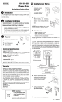
See reverse for installation guide
4iE Smart WiFi Thermostat operating guide
Welcome to
Warmup
2
3
If you use a smartphone to access MyWarmup, you will be shown a mobile version which gives quick access to
important features like Smart Overrides. If you want to set up your 4iE using a smartphone you will have to ensure
you access the desktop version of the website. This can be changed in the browser settings of your phone or by
clicking the link at the bottom of the mobile page.
You can also program and set-up your 4iE with your tablet or computer by visting my.warmup.com.
MyWarmup
To turn the thermostat on or off, press the power button on the bottom of the device for 3 seconds.
The icons at the bottom of the screen are your WarmApps. These can be set up on MyWarmup to show traffic and
journey alerts, along with your energy saving advice
If you do not press any button for 1 minute, the 4iE screen will dim and revert to the home screen. To wake the 4iE
just tap the screen or press Wake.
The 4iE default screen is the home screen. Pressing the temperature figure in the centre of the screen allows you
to override it. Pressing the menu button allows you to start programming and setting up the 4iE. You’ll often find a
help button on pages with several options to give more information.
Introduction
4
Internet Settings
Time
Date
Daylight Savings
Heating type
Temperature Display
•
•
•
•
•
•
Theme
Brightness
Audio Feedback
Floor type
Heating control type
Heating Program Schedule
Energy Monitor settings
•
•
•
•
•
•
•
5
Ensure you choose the correct System Type. Electric (underfloor), Hydronic (underfloor) or Conventional
(central heating with radiators).
Important!
Language
•
On initial power up the 4iE will ask you to connect to a WiFi network. Once connected you will be asked
to create a MyWarmup account. If you skip the WiFi connection stage, you will be guided through an
offline setup procedure (with the options shown below) and can set up a MyWarmup account at a later
date.
Getting Started
6
No WiFi Connection
7
When your 4iE is connected to the internet, just enter the unique codes displayed on the connection
screen into MyWarmup. Your 4iE will then be connected.
Not connected to Server
If you see these icons, call Warmup for
24/7/365 assistance on 0845 345 2288
When you’ve received your account activation email, you can connect your 4iE to the account. Ensure
your 4iE is connected to the internet. If you see an error icon on the homescreen (see below), then
your thermostat is not connected to the internet.
If you cannot connect to the internet, you may skip this stage and connect at a later date.
Enter your email address and create a password for your account. You will be sent a confirmation email
when your account is set up. Make sure you check your spam folder as well as your inbox.
Once your 4iE is powered up, you need to create your MyWarmup account. Navigate your web browser
to my.warmup.com
Connecting to MyWarmup
8
9
Remember: The 4iE can also learn your schedule and program itself. To activate this, set it
into Learning Mode on MyWarmup
You can add up to 5 Comfort Periods per day and when you’ve set what you want, just press Done.
You’ll see the summary of your program which you can edit by repeating the steps above, or just press
Accept to set your program.
The programming works by setting Comfort Periods of warm temperatures, shown with a green line.
Any time not covered by a Comfort Period will use a lower Setback temperature to save energy. The
default setback temperature is 16°C and you can change this once you’ve set up your program if needed.
To adjust the program, you must highlight the days that you want to program by pressing them, then
press Program. You can select multiple days in any combination, such as weekdays only, to program
separate weekday and weekend temperatures. To do this, program all the weekdays at once and then
program the weekend when you’re finished.
With your 4iE, you can choose to set a custom heating schedule, fixed temperature or a preset program
designed for different rooms.
Set your heating program
07:00
11:00
18:00
23:00
Sat-Sun
10
06:00
08:00
19:00
23:00
Mon-Fri
Time
06:00
08:00
18:00
22:00
07:00
11:00
18:00
22:00
25
18
20
15
Time
23
18
23
10
23
10
23
10
Temp
Kitchen
25
10
20
15
Temp
Bathroom
Below is a summary of the Preset Programs
18:00
21:30
08:00
18:00
20:00
25
10
20
10
06:00
08:00
20:00
23:00
Time
25
10
20
10
Temp
23
20
10
23
10
Temp
Living Room
06:00
08:00
20:00
23:00
Time
Bedroom
You can select a preset program schedule to get you started. You can edit the program whenever you
like by following the steps in Set Your Heating Program
Preset Programs
11
Select Frost Protect mode to set your heating to 5°C. This will help protect your home from frost and
will run continuously until you raise the temperature again.
Frost Protect
Enter the maximum temperature and the time required to reach that temperature to set Gradual Start.
Different floors have different requirements so please contact your floor installer or supplier for advice
on how to set Gradual Start correctly.
Gradual Start allows you to bring your floor up to temperature slowly, which is required for some floor
finishes such as solid wood, and can also be found in the Program menu.
Gradual Start
Just set the start and end times of your holiday, or leave the end time as Unspecified, if you want
Holiday Mode to run indefinitely. Then set the temperature you want when you’re away.
Holiday Mode allows you to override your schedule with a fixed temperature over a number of days.
This helps you save energy when you know you’ll be away for a while by setting a lower temperature.
Holiday Mode can be found in the Program menu
Holiday Mode
12
13
When you’ve set up the Energy Monitor you can view the estimated usage or cost over a selected
time period. If you have a standard/low energy tariff, the amount and cost of energy used during
the standard period will be displayed in dark green and the amount used in the low period will be
displayed in light geen
You will also need to enter the cost of your energy, in order to calculate the running cost of your
system. Press Energy Settings, and select if you have a single rate tariff or a standard/low energy
tariff (where you have a discounted cost during part of the day). Enter your cost per KWH and relevant
currency and, if required, the time the low energy tariff starts and stops and the discounted cost during
that time.
You will need to enter the power of your system, and in some cases, the efficiency. If you do not know
these, speak to your installer or go to www.warmup.co.uk and use our online Heat Requirement
Calculator.
The 4iE learns how you use your system and how your house reacts to the heating and weather. It can
give you an estimate of your energy usage and the running cost of your system.
Energy Monitor
manually set date (only available without WiFi connection)
set daylight savings (only available without WiFi connection)
Set date
Daylight savings
starts heating early so it’s up to temperature at the right time
Control air/floor
Adaptive learning
set a lock code and limits for when the lock is active
turn the ‘click’ sound on or off
Choose a WiFi network and enter the password if required
Lock
Audio Feedback
Network
14
choose a theme for the main screen
change the screen brightness for normal use and standby
Display brightness
change the screen background (upload your own on MyWarmup)
Home screen style
Background
Display/Audio
choose celsius or farenheit
use air or floor sensor as main measurement
Temperature format
Heating preferences
manually set time (only available without WiFi connection)
Set time
Time
The 4iE can be configured in different ways to suit you. The functions that can be accessed in the
Settings menu include:
Settings
This will restore all the factory default settings. You can also hold the button on the rear of the front
module for 10 seconds to perform a system reset
15
Set the offset of the sensors to improve accuracy
Reset
Set the maximum temperature and time required to reach that temperature
Gradual Start
Choose if the floor probe is being used as a Floor or Amb (ambient) sensor
This allows one thermostat to control another
1.
Choose which thermostat is Master and which is Relay
2.
Use low voltage cable to connect terminal 6 of both thermostats
3.
Use low voltage cable to connect terminal 7 of both thermostats (in addition
to floor sensor cables on the Master thermostat)
4.
Set Relay thermostat to Relay mode first, then set the Master thermostat to
Master mode
5.
Program the Master thermostat. The Relay thermostat will no longer use its
sensors, it will follow the Master thermostat
Master/Relay
Offset
This is a feature specifically for France. You must also connect Fil Pilote to terminal 1
Fil Pilote
Probe application
Regulator mode controls the heating in 10 minute cycles. The number you enter is
the number of minutes in every 10 minute cycle that the heating will be on. This
mode will not use the floor or air sensors for measurement
Regulator
Set the specification of the probes. You can also choose to hide the error message if you do not want to
connect a probe
Set the temperature limits for your floor type. User Defined lets you set custom
limits
Heater limits
Heater settings
Probes
These options can affect the performance of your thermostat and should only be modified by an
experienced professional or under the instruction of Warmup Technical Support
Advanced settings
16
Connecting the 4iE directly to extra low voltage or volt-free
boilers may cause damage to the boiler circuit.
For extra low voltage or volt-free systems a contactor must
be used. Contact Warmup for more details.
Master/Relay installation: (connecting 2 stats together)
6. Connect to terminal 6 on other thermostat
7. Connect to terminal 7 on other thermostat
Second sensor installation: (2nd floor probe or exterior probe)
6. Connect to 1st wire of external sensor/ 2nd floor sensor
7. Connect to 2nd wire of external sensor/ 2nd floor sensor
2.
3.
4.
5.
see numbering on diagram below
Connect to Power Supply (Live – MAX 240V)
Connect to Power Supply (Neutral – MAX 240V)
Connect to Boiler circuit (Neutral if present– MAX
3600W/ 16 Amps)
Connect to Boiler circuit (240V Switch Live – MAX
3600W/ 16 Amps)
Special Installation
see numbering on diagram below
7.
8.
5.
Central heating Installation
8.
7.
5.
2.
3.
4.
2.
3.
4.
Connect to Power Supply (Live – MAX 240V)
Connect to Power Supply (Neutral – MAX 240V)
Connect to wiring centre (Neutral if present – MAX
3600W/ 16 Amps)
Connect to wiring centre (Switch Live – MAX 3600W/ 16
Amps)
Connect to 1st wire of floor sensor (colour not important)
Connect to 2nd wire of floor sensor (colour not important)
see numbering on diagram below
see numbering on diagram below
Connect to Power Supply (Live – MAX 240V)
Connect to Power Supply (Neutral – MAX 240V)
Connect to Warmup heater(s) (Neutral – MAX 3600W/
16 Amps)
Connect to Warmup heater(s) (Live – MAX 3600W/ 16
Amps)
Connect to 1st wire of floor sensor (colour not
important)
Connect to 2nd wire of floor sensor (colour not
important)
Hydronic Underfloor Installation
Electric Underfloor Installation
17
5.
6.
4.
3.
2.
1.
Push excess wire back through the wall box and
insert thermostat back module into wall box.
Put fixing screws through mounting holes and
tighten.
Ensure that thermostat is straight before tightening
completely.
Replace thermostat front housing;
i) align and sit front housing on to hinges,
ii) push lower half of front housing until a
‘click’ is heard.
Ensure front housing is securely fixed.
IMPORTANT: Tighten both retaining screws
Mounting Thermostat thermostat
4
33
1.
2.
“er1”: This will occur if no floor sensor is detected
“er2”: This will occur if the floor sensor has a short
circuit
Your thermostat can give you two error indications:
Error Messages
You can now power up the thermostat and begin the
programming process. An easy to follow menu will
guide you through the rest. If you want to turn on / off
the thermostat and heating system then hold down the
recessed button on the bottom of the stat for 3 seconds
Powering Up
OB
18
The thermostat should be installed inside a single gang electrical wall box that is at least 30mm deep. For optimal performance
the thermostat should be located in an area with good ventilation. It should not be beside a drafty window/ door, in direct
sunlight or above another heat generating device (e.g. radiator or TV).
The thermostat is designed for operation between 0°C and 55°C with relative humidity less than 80%.
Location
WARNING – Important safety note
This product uses mains voltage electricity and work should only be carried out by a qualified electrician. You should always
isolate the power supply before attempting to install or repair the 4iE thermostat. The thermostat should not be put into
operation unless you are certain that the entire heating installation complies with current general safety requirements for
electrical installations. Electrical installation to be in accordance with latest IEE Wiring Regulations and appropriate Statutory
Regulations.
Electrical Specification:
•
Supply voltage: 230V +/-15% at 50Hz
•
Thermostat is not designed for use with intermittent power supply.
•
Maximum Switch Load: 16A resistive
•
Insulation Class : II
•
Housing : IP33
•
Standards: EN60730-1 & EN60730-2-9 standards
The thermostat is not a safety device. In order to avoid damaging your system the correct system and floor type should be
selected during the thermostat programming process.
The 4iE thermostat is designed to aid in the comfort of your home by providing timed regulation of your heating system. The
thermostat is designed to receive temperature input signals from the following sensors:
1.
Air sensor located inside thermostat
2.
Floor sensor installed in floor if using underfloor heating (see Warmup heater instructions for details)
3.
Optional 2nd sensor
Introduction
19
Unscrew both closing screws (bottom of stat) until
they will not turn any further.
Release front housing by gripping lower half of
outer frame and pulling outwards then upwards
Place front housing somewhere safe
Run all wires to the wall box. Check to ensure
that you have included the following:
Power (Live and Neutral)
Heater (Live and Neutral or Switch Live only)
Floor sensor
Fil pilote (if necessary)
External/ 2nd floor Sensor (if necessary)
Pull wires through wall box and complete
terminal wiring.
NOTE: Always ensure that the sensor cable is installed
in a separate
conduit to the power cables supplying the thermostat
and heating system.
If connecting more than two heaters, an electrical
junction box will be required.
IMPORTANT: Ensure that multi stranded wires are fully
inserted into the terminals and secured tightly. Any
loose strands should be trimmed as they could cause a
short-circuit.
5.
3.
4.
2.
1.
Separate the front housing of thermostat from wall
module:
Installation
Installation guide
Lifetime warranty also available. Contact Warmup or visit www.warmup.co.uk for details
Warranty
Warmup plc warrants this product, to be free from defects in the workmanship or materials, under normal use and service, for
a period of three (3) years from the date of purchase by the consumer. If at any time during the warranty period the product is
determined to be defective, Warmup shall repair or replace it, at Warmup’s option.
If the product is defective, please either,
(i) return it, with a bill of sale or other dated proof of purchase, to the place from which you purchased it, or
(ii) contact Warmup. Warmup will determine whether the product should be returned, or replaced.
This warranty does not cover removal or reinstallation costs, and shall not apply if it is shown by Warmup that the defect or
malfunction was caused by failure to follow the instruction manuals, incorrect installation or damage which occurred while the
product was in the possession of a consumer.
Warmup’s sole responsibility shall be to repair or replace the product within the terms stated above.
WARMUP SHALL NOT BE LIABLE FOR ANY LOSS OR DAMAGE OF ANY KIND, INCLUDING ANY INCIDENTAL OR CONSEQUENTIAL DAMAGES
RESULTING, DIRECTLY OR INDIRECTLY, FROM ANY BREACH OF ANY WARRANTY, EXPRESS OR IMPLIED, OR ANY OTHER FAILURE OF THIS
PRODUCT. THIS WARRANTY IS THE ONLY EXPRESS WARRANTY WARMUP MAKES ON THIS PRODUCT. THE DURATION OF ANY IMPLIED
WARRANTIES, INCLUDING THE WARRANTIES OF MERCHANTABILITY AND FITNESS FOR A PARTICULAR PURPOSE, IS HEREBY LIMITED TO THE
THREE-YEAR DURATION OF THIS WARRANTY.
This Warranty does not affect your statutory rights.
702 & 704 Tudor Estate
Abbey Road
Park Royal
London
NW10 7UW
0845 345 2288
UK
Contact Us