1
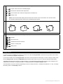
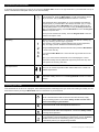
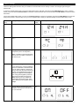
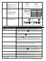
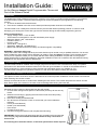
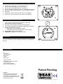
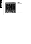
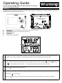
Operating Guide:
for the Warmup tempo Digital Programmable Thermostat
Part of the Element Series
Introduction
The tempo has been designed with simplicity in mind and is highly intuitive in its programming. The sliders and simple rotary control
make the setting of the thermostat quick and easy.
1
2
3
4
element
series
tempoTM
exclusively from
(1)
(2)
(3)
(4)
(5)
(6)
Rotary Control (Turn clockwise to increase and anti clockwise to decrease.)
Main Button
Program Slide control (only used during programming)
Mode Slide control
Reset Button
Replaceable CR2032 battery
8
1.
Normally shows the current temperature in the room. This can be either the floor temperature or the air temperature. (See icon
4). When you are setting a program or manual temperature this icon will temporarily show the set temperature.
2.
During programmed operation this thermometer will show whether the thermostat is at “Comfort”
The
3.
4.
or “Setback”
temperature.
icon will be displayed when “Comfort -1/ -2 is the target temperature. (Only used with the Fil Pilote)
This icon
is displayed when the heating is on.
These icons show the type of temperature regulation being used.
Floor Sensor
Regulator
Air Sensor
(This mode should only be used in special situations, please contact Warmup for additional information).
ELT-01-XX-01 - Operating guide V1.0 © Warmup plc - 2013
5.
These icons show the mode in which your thermostat is being used:
Program mode will run the scheduled program
Manual mode will hold a fixed temperature
Frost Protection will not allow the temperature to fall below 5°C
Standby mode
NOTE: When the thermostat displays both the manual and comfort icon the thermostat is in a manual override
and will hold a fixed temperature until the next scheduled program period.
6.
These icons show which time of day is being programmed.
Morning
Day
Evening
7.
This area shows the current time and day of the week.
8.
These are error icons (see trouble shooting section) or special command icons:
Night
Fil Pilote
Floor sensor error
Overheat limit has been reached
There is no mains power
Battery is low
Getting started
In order to program the tempo thermostat all you need to do is slide the Program Slide control from the top position to the bottom
position, customising the program along the way.
If you make a mistake, return the Program Slide control to the previous position and start again. In order to change a setting value,
turn the Rotary Control. Pressing the Main Button will accept the value and move you on to the next value that needs setting.
The tempo thermostat has a number of “Installer Settings”. If your thermostat has been installed correctly and is working then it is
unlikely that you will need to change these again. For additional details see “Installer settings” section.
Your thermostat can be set so that the programming is done for “all days the same”, “weekday and weekend” or “7 day”. To change
this setting, see the “set time/day” section.
ELT-01-XX-01 - Operating guide V1.0 © Warmup plc - 2013
Programming the thermostat
To program your thermostat all you need to do is move the Program Slide control on the right hand side of your thermostat from top to
bottom. The table below will explain what you can do at each step.
Turn the Rotary Control to change the current clock time. Once the clock
time has been set, press the Main Button, you will now be able to set the
day of the week. Turn the Rotary Control to select the correct day.
Set Time /Day
Your thermostat will by default allow you to set a weekday and weekend
program (5-2d). If you would like to set “all days the same” (1d) or “7 day”
programs (7d) then hold the Main Button for 5 seconds whilst in the set
time/day slide position. Once in this mode, turning the Rotary Control will
allow you change this setting. Push the Main Button or move the Program
Slide to accept the value.
Once you have set the time and day, move the Program Slide to the next
position to accept the value.
Set Timing
1
2
3
4
Set Temperatures
Done
When in any of these positions you can set the start time for “morning” (1),
”day” (2), ”evening” (3) and “night “ (4) periods.
The “morning” and “evening” periods will follow the comfort temperature,
“day” and “night” periods will follow the setback temperature.
Using the Rotary Control, select the start time and press the Main Button
to move to the next day.
If you hold the Main Button for 3 seconds it will copy the start time to the
next day.
Tip - If you want to set the thermostat so that it is keeping the comfort
temperature all day and only setback at night, then just set the “day” start
time equal to the “evening” start time.
Here you can set the temperature which will be used for the comfort and
setback temperatures.
Move the Program Slide control to the lowest position in order to start your
thermostat. Heating will not occur if the Program Slide control is not in this
position.
Selecting your mode
Your thermostat can be set to run a program, hold a fixed temperature, efficiently protect your home from freezing or standby. You can
select these modes by moving the Mode Slide control on the bottom of your thermostat.
Standby
The thermostat will not come on.
NOTE: The thermostat is still connected to the mains electricity supply
and your heating system is not isolated. Always isolate from the mains
before undertaking any maintenance.
Frost Protection
Manual
Auto
The thermostat will not let the temperature fall below 5°C.
The thermostat will hold a fixed temperature. Just turn the Rotary Control
to change the temperature.
In this position your thermostat will run the program you have set.
If you would like to temporarily adjust the temperature, just turn the Rotary
Control. At the start of the next heating period, your thermostat will
automatically resume your programming schedule.
ELT-01-XX-01 - Operating guide V1.0 © Warmup plc - 2013
Installer settings
These are settings that should be set by the installer of the thermostat and are unlikely to need to be changed again during the
product’s life.
To enter the installer setting mode, remove the thermostat from the wall plate. Press and hold the Main Button and, using a pointed
device, press and release the Reset Button on the back of the thermostat. After 5 seconds release the Main Button on the front of the
thermostat.
Once in the installer setting mode you can turn the Rotary Control to change your selection and press the Main Button to accept your
setting and proceed to the next step. Once you have completed all the steps you will automatically exit the installer setting mode.
Installer
Step
Setting Configured
Default
Value
1.
Change clock format (12hr/24hr)
“24”
2.
Change unit of measurement (Degree
C/F)
°C
3.
Change sensor used to target
temperature (Floor/ Air/ Regulator)
Floor
LCD Example
Note: In regulator mode the thermostat
will run for a set number of minutes in a
10 minute cycle.
4.
Set Floor Sensor Type
If you already have a sensor installed a
sensor for a different model thermostat
you can use this setting to change the
sensor value and allow the thermostat to
function. The possible options are NTC
10K (probe supplied with the tempo)
NTC 12K (probe supplied by Warmup
with previous models of thermostat).
Note: Warmup can only validate the
thermostats performance when used
with a Warmup probe supplied with the
tempo.
5.
Decide whether the thermostat uses
Adaptive Learning to pre heat the room
for your schedule.
On
ELT-01-XX-01 - Operating guide V1.0 © Warmup plc - 2013
Fil Pilote (France only)
The thermostat can obey the 6
standard
commands of fil pilote (pilot
wire) Contact
Warmup for additional details.
7.
Set Overheat limit to protect
your floor.
30°C
Please note, the tempo
will only allow you to set a
temperature 2°C/4°F lower
than the Overheat limit
8.
Maximum Overheat Limits
Tiles
40°C / 104°F
Stone
40°C / 104°F
Wood / Laminate
28°C / 86°F
Carpet
28°C / 86°F
Vinyl
28°C / 86°F
Set an offset value to calibrate 0°C
the temperature reading of your
thermostat sensors
Error messages / Trouble shooting
The thermostat is not controlling the
temperature
Floor sensor error
Overheat
Low battery
Ensure that the Program Slide is in the run position (lowest point) and that the
Mode Slide control (bottom) is in the manual or program positions.
If you see the floor sensor error icon
or “ - - “ on the screen it means that your
thermostat has been unable to detect the temperature of the floor. Please contact
Warmup.
If you see the overheat icon
this means that your floor has become too hot
and the heating has been suspended. Please contact Warmup.
The low battery icon
will display when the battery needs to be replaced. The
thermostat must be connected to the mains electricity supply in order to work, it
is not designed to be used with an intermittent power supply. If the battery is not
installed then your thermostat will not be able to maintain the clock time if power is
lost.
Heating starts too early
If your heating is coming on too early, then this may be because the Adaptive
Learning function is turned on. This function allows your thermostat to learn how
long it will take to heat up to ensure it is the correct temperature at the start of the
comfort periods. See “installer settings” section of this guide.
Incorrect calibration
Your thermostat should not need any calibration, however if you would like to apply
an offset to the temperature settings see the “installer settings” section.
No mains electricity
If you see the no mains power icon
this means that the thermostat is not
receiving power. Check that the thermostat logic module is properly installed on
the power module and that the 230V mains electricity supply is connected.
Regulator mode (Reg) is displayed
In this mode your thermostat will come on for a set number of minutes in a 10
minute cycle. The thermostat will not use the temperature for control. Please
contact Warmup for additional details.
Fil Pilote (FP) is displayed
The thermostat can obey the 6 standard commands of fil pilote (pilote wire).
Please contact Warmup for additional details. (France only)
HI or LO is displayed
The thermostat will display “HI” if the ambient temperature exceeds 50°C (122°F)
and “LO” when the ambient temperature falls below 0°C (32°F).
ELT-01-XX-01 - Operating guide V1.0 © Warmup plc - 2013
Warranty
Warmup plc warrants this product, to be free from defects in the workmanship or materials, under normal use and service, for a period
of three (3) years from the date of purchase by the consumer. If at any time during the warranty period the product is determined to be
defective, Warmup shall repair or replace it, at Warmup’s discretion.
If the product is defective, please either,
(i) return it, with a bill of sale or other dated proof of purchase, to the place from which you purchased it, or
(ii) contact Warmup. Warmup will determine whether the product should be returned, or replaced.
This warranty does not cover removal or reinstallation costs, and shall not apply if it is shown by Warmup that the defect or malfunction
was caused by damage which occurred while the product was in the possession of the end user.
Warmup’s sole responsibility shall be to repair or replace the product within the terms stated above.
WARMUP SHALL NOT BE LIABLE FOR ANY LOSS OR DAMAGE OF ANY KIND,
INCLUDING ANY INCIDENTAL OR CONSEQUENTIAL DAMAGES RESULTING,
DIRECTLY OR INDIRECTLY, FROM ANY BREACH OF ANY WARRANTY,
EXPRESSED OR IMPLIED, OR ANY OTHER FAILURE OF THIS PRODUCT.
THIS WARRANTY IS THE ONLY EXPRESS WARRANTY WARMUP MAKES ON
THIS PRODUCT. THE DURATION OF ANY IMPLIED WARRANTIES, INCLUDING
WARRANTIES OF MERCHANTABILITY AND FITNESS FOR A PARTICULAR
PURPOSE, IS HEREBY LIMITED TO THE THREE-YEAR DURATION OF THIS
WARRANTY.
This Warranty does not affect your statutory rights.
Please register your product at: www.warmup.co.uk
Customer care
For any questions regarding product installation or operation, please contact Warmup at:
UK
Warmup Plc
702 Tudor Estate
Abbey Road
London
NW10 7UW
T: 0845 345 2288
International: + 44 208 453 6868
F: 0845 345 2299
E-mail: [email protected]
Website: www.warmup.co.uk
ELT-01-XX-01 - Operating guide V1.0 © Warmup plc - 2013
Installation Guide:
for the Warmup tempo Digital Programmable Thermostat
Part of the Element Series
Introduction
The tempo thermostat is designed to aid in the comfort of your home by providing timed regulation of your Warmup
underfloor heating system. The thermostat is designed to receive temperature input signals from the following
sensors:
1. Air sensor located inside the thermostat
2. Floor sensor installed in the floor to be heated (see Warmup heater instructions for details)
The thermostat is not a safety device and should only be used with Warmup heating products. In order to avoid
damaging your flooring the correct floor type must be selected during the thermostat programming process.
Electrical Specification:
• Supply voltage: 230V +/-15% at 50Hz
• Thermostat is not designed for use with intermittent power supply.
• Maximum Switch Load: 16A resistive
• Insulation Class : II
• Housing : IP20
• Sensor NTC : 10K @ 25°C
• Standards: EN60730-1 & EN60730-2-9
• Meets LVD and EMC directives for safety and electromagnetic compatibility
WARNING – Important safety note
This product uses mains voltage electricity and work should only be carried out by a qualified electrician. You should
always isolate the power supply before attempting to install or repair the tempo thermostat. The thermostat should
not be put into operation unless you are certain that the entire heating installation complies with current general
safety requirements for electrical installations. Electrical installation must be in accordance with the latest IEE Wiring
Regulations and appropriate Statutory Regulations.
Thermostat location
The thermostat should be installed inside a single gang electrical wall box that is at least 32mm deep. For optimal
performance, the thermostat should be located in an area with good ventilation. It should not be installed beside a
drafty window/door, in direct sunlight or above another heat generating device (e.g. Radiator or TV).
The thermostat is designed for operation between 0°C and 50°C with relative humidity less than 80%.
Location and installation of floor sensor
The optimum location of the floor sensor is described in each Warmup heater installation manual. Refer to that manual
when selecting floor sensor location.
Warmup recommend the use of conduit when installing the floor sensor. The conduit will protect the sensor and will
allow easier repair of the sensor in the case of sensor damage after flooring has been laid.
Installation:
Separate the front housing of thermostat from the wall module:
1. Unscrew both closing screws (bottom of thermostat) until they will not turn any
further.
2. Release front housing by gripping the lower half of outer frame and pulling
outwards then upwards.
3. Place front housing somewhere safe.
4. Run all wires to the wall box. Check to ensure that you have included the
following:
• Power (Live and Neutral)
• Heater (Live and Neutral)
• Floor sensor
• Fil pilote (France only)
5. Pull wires through the wall box and complete terminal wiring.
1
2
3
4
IMPORTANT: Ensure that multi strand wires are fully inserted into the terminal and
secured tightly. Any loose strands should be trimmed as they could cause a
short-circuit.
If connecting more than two heaters, an electrical junction box will be required.
ELT-01-XX-01 - Installation guide V1.0 © Warmup plc - 2013
Normal electrical installation (see numbering on diagram to right)
1.
2.
3.
4.
5.
6.
7.
8.
Connect to Fil Pilote (F.P.) - only for use in France
Connect to Power Supply (Live – MAX 240V)
Connect to Power Supply (Neutral – MAX 240V)
Connect to Warmup heater(s) (Neutral – MAX 3600W/ 16 Amps)
Connect to Warmup heater(s) (Live – MAX 3600W/ 16 Amps)
Not Used
Connect to 1st wire of floor sensor (colour not important)
Connect to 2nd wire of floor sensor (colour not important)
(NOT USED)
20
Mounting thermostat into the wall box
1. Push excess wire back through the wall box and insert
thermostat back module into wall box.
2. Put fixing screws through mounting holes and tighten.
3. Ensure that thermostat is straight before tightening completely.
4. Replace thermostat front housing:
• Align and sit front housing on to hinges
• Push lower half of front housing until a ‘click’ is heard.
5. Ensure front housing is securely fixed.
6. IMPORTANT: Tighten both retaining screws.
Powering-up
You can now power-up the thermostat and begin the programming
process.
Contact Warmup
UK
Warmup Plc
702 Tudor Estate
Abbey Road
London
NW10 7UW
T: 0845 345 2288
International: + 44 208 453 6868
F: 0845 345 2299
E-mail: [email protected]
Website: www.warmup.co.uk
Patent Pending
Disposal
Appliances with this symbol must
not be disposed of with general
waste. Seek guidance from your local
government or the retailer where you
purchased the product.
ELT-01-XX-01 - Installation guide V1.0 © Warmup plc - 2013