1
20
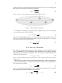
If the TX, the RX or the environment is in motion over time, the transmitted signal
experiences Doppler effect. Thus, in the received spectrum (Doppler spectrum), several frequency components may be seen even if only one was transmitted. The spread
of the frequencies in the RX caused by the Doppler effect is called as Doppler spread.
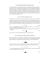
The width of the Doppler spectrum is called as Doppler bandwidth, BD [3] [17]. Channel coherence time TC is inversely proportional to the Doppler bandwidth and it can be
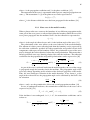
written as [3]
1
.
(31)
TC ≈
BD
In a multipath channel, the multipath propagated components leaves from the TX
antenna and arrives to RX antenna in some specific angle with respect to some reference direction, which is usually the direct link path between the TX and RX. These
angles are called as angle of departure (AoD) and angle of arrival (AoA), respectively.
In three dimensional (3D) space, AoA and AoD is often defined separately for azimuth
and elevation domains. Thus, the azimuth and elevation angles can be extended into
3D as direction of arrival (DoA) and direction of departure (DoD). The Angular spread
is a parameter to describe the spatial order of the channel. [3]
2.3.3. Deterministic channel models
The deterministic channel models tries to estimate the path loss and phase difference
experienced by the signal as it propagates trough the channel. The deterministic path
loss models, such as the free space path loss model presented in (7), are used to calculate the path loss of the channel. The models include a number of approximations and
all of the radio propagation phenomena are not usually taken into account. This means
that we have to simplify the geometry of the environment in order to estimate the most
significant multipaths from the impulse responses. The models are parameterized to fit
to the propagation environment.
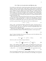
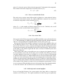
One deterministic channel model, the simplified path loss model, is defined as
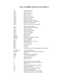
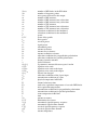
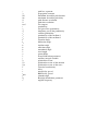
L = Lref − 10γ log10 [
d
],
d0
(32)
where L is the path loss, γ is the path loss exponent, Lref is the path loss at the reference
distance d0 and d is the distance in meters. [3]
2.3.4. Indoor channel modeling
The indoor environment has many characteristics making them different from outdoor
environment. At indoor environment, the walls are limiting the radio wave propagation
especially in higher frequencies, because of high wall penetration loss. On the other
hand, the walls gives a possibility to isolate the area better and hence avoid interference coming from outside or other rooms. The reflection, diffraction and free space
propagation are the main propagation phenomena at the indoor environment if the penetration loss of the walls are assumed to be high. Long corridors makes it possible to
transmit signals trough multiple reflections from the source to the destination. [3]