1
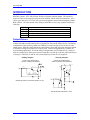
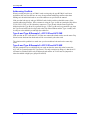
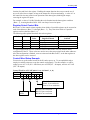
^1 USER MANUAL
^2
Accessory 10E
^3 Opto 48-Bit Output Board
^4 3xx-603299-xUxx
^5 September 24, 2003
Single Source Machine Control
Power // Flexibility // Ease of Use
21314 Lassen Street Chatsworth, CA 91311 // Tel. (818) 998-2095 Fax. (818) 998-7807 // www.deltatau.com
Reading and Writing to Node Addresses
1
Copyright Information
© 2003 Delta Tau Data Systems, Inc. All rights reserved.
This document is furnished for the customers of Delta Tau Data Systems, Inc. Other uses are
unauthorized without written permission of Delta Tau Data Systems, Inc. Information contained in
this manual may be updated from time-to-time due to product improvements, etc., and may not
conform in every respect to former issues.
To report errors or inconsistencies, call or email:
Delta Tau Data Systems, Inc. Technical Support
Phone: (818) 717-5656
Fax: (818) 998-7807
Email: [email protected]
Website: http://www.deltatau.com
Operating Conditions
All Delta Tau Data Systems, Inc. motion controller products, accessories, and amplifiers contain
static sensitive components that can be damaged by incorrect handling. When installing or handling
Delta Tau Data Systems, Inc. products, avoid contact with highly insulated materials. Only
qualified personnel should be allowed to handle this equipment.
In the case of industrial applications, we expect our products to be protected from hazardous or
conductive materials and/or environments that could cause harm to the controller by damaging
components or causing electrical shorts. When our products are used in an industrial environment,
install them into an industrial electrical cabinet or industrial PC to protect them from excessive or
corrosive moisture, abnormal ambient temperatures, and conductive materials. If Delta Tau Data
Systems, Inc. products are directly exposed to hazardous or conductive materials and/or
environments, we cannot guarantee their operation.
Accessory 10E
Table of Contents
INTRODUCTION ...................................................................................................................................... 1
Output Drivers ......................................................................................................................................... 1
HARDWARE SETUP................................................................................................................................ 3
E1-E4: I/O Gate Transfer Jumpers .................................................................................................... 3
E5: I/O Gate Data Clock Select ......................................................................................................... 3
E6A-E6H: Node Select Jumpers......................................................................................................... 3
E10-E21*Sinking or Sourcing Output Select ...................................................................................... 4
Hardware Address Limitations ................................................................................................................ 4
Addressing Conflicts............................................................................................................................ 5
Type A and Type B Example 1: ACC-10E and ACC-36E ................................................................... 5
Type A and Type B Example 2: ACC-10E and ACC-65E ................................................................... 5
USING ACC-10E WITH UMAC TURBO............................................................................................... 7
UMAC-Turbo Memory Mapping for ACC-10E...................................................................................... 7
Control Register ....................................................................................................................................... 7
Direction Control Bits ......................................................................................................................... 7
Register Select Control Bits................................................................................................................. 8
Control Word Setup Example .............................................................................................................. 8
Accessory 10E I/O M-Variables for UMAC Turbo................................................................................. 9
MACRO-STATION I/O TRANSFER.................................................................................................... 11
MACRO I/O Gate Locations ............................................................................................................. 11
MACRO Station I/O Node Transfer Addresses ................................................................................. 11
PMAC2 Ultralite I/O Node Addresses............................................................................................... 12
PMAC2 Turbo Ultralite I/O Node Addresses.................................................................................... 12
MACRO I/O Software Settings ............................................................................................................. 12
Reading and Writing to Node Addresses ............................................................................................... 18
Example:............................................................................................................................................ 18
Example Setup:.................................................................................................................................. 18
Active Nodes for Compact MACRO I/O Station................................................................................ 19
PMAC2 Ultralite Example M-Variable Definitions .............................................................................. 20
PMAC2 Turbo Ultralite Example M-Variable Definitions.................................................................... 21
Example 1: 48 Inputs 48 Outputs Using 3X16-Bit Transfers ................................................................ 22
Example 2: 48 Inputs 48 Outputs Using 1X24-Bit Transfers ................................................................ 23
Example 3: 36 Inputs 36 Outputs Using 1X72-Bit Transfers ................................................................ 24
Setting up Control Word for MACRO IO.............................................................................................. 25
APPENDIX – MACRO Legacy Systems .............................................................................................. 26
E1-E4: I/O Gate Transfer Jumpers .................................................................................................. 26
I/O TERMINALS ..................................................................................................................................... 29
TB1 Top (12-Pin Terminal Block) ..................................................................................................... 29
TB2 Top (12-Pin Terminal Block) ..................................................................................................... 29
TB3 Top (3-Pin Terminal Block) ....................................................................................................... 30
TB1 Bottom (12-Pin Terminal Block)................................................................................................ 30
TB2 Bottom (12-Pin Terminal Block)................................................................................................ 30
TB3 Bottom (3-Pin Terminal Block).................................................................................................. 31
DB15 Style Connector J1 Top – Outputs 1 through 12 ......................................................................... 31
J1 Top Connector .............................................................................................................................. 31
DB15 Style Connector J2 Top – Outputs 12 through 24 ....................................................................... 32
J2 Top Connector .............................................................................................................................. 32
DB15 Style Connector J1 Bottom – Outputs 25 through 36.................................................................. 32
J1 Bottom Connector......................................................................................................................... 32
DB15 Style Connector J2 Bottom – Outputs 37 through 48.................................................................. 33
J2 Bottom Connector......................................................................................................................... 33
Table of Contents
i
Accessory 10E
UBUS PINOUTS ...................................................................................................................................... 35
P1 UBUS (96-Pin Header).................................................................................................................... 35
ii
Table of Contents
Accessory 10E
INTRODUCTION
The PMAC Accessory 10E is a general-purpose output board to the UMAC-Turbo or UMACMACRO systems. ACC-10E provides 48 lines of optically isolated outputs. The actual I/O
writes are carried out using a special form of M-variables, which will be described later. ACC10E is one of the series of 3U rack I/O accessories designed to transfer data through the UMAC
BUS (UBUS). The other boards in the family of MACRO I/O Accessory products include the
following:
ACC-9E
ACC-10E
ACC-11E
ACC-12E
ACC-14E
48 optically isolated inputs
48 optically isolated outputs, low power
24 inputs and 24 outputs, low power, all optically isolated
24 inputs and 24 outputs, high power, all optically isolated
48-bits TTL level I/O
Output Drivers
The output drivers are organized in a set of six 8-bit groups. Each group (each byte) may be
ordered with either current sourcing drivers (default) or with current sinking drivers. The default
configuration of this accessory board uses UDN2981 current sourcing drivers for the six 8-bit
output groups. With this configuration, the current drawn from each output line should be limited
to 100 mA at voltage levels between 12 and 24 volts. Custom configurations are available for
current sinking applications. In current sinking configurations one ULN2803 driver is used per
each 8-bit output group. Each open collector output line can sink up to 100 mA when pulled up to
a voltage level between 12 and 24 volts (external pull-up resistors are not supplied).
Sinking Outputs:
Sourcing Outputs:
OUTPUT CHIP EQUIVALENT
CIRCUIT UDN2981 FOR SOURCING
OUTPUT CHIP EQUIVALENT
CIRCUIT ULN2803 FOR SINKING
+V
+V
20K
2.7K
7.2K
3K
7.2K
3K
INVERTING, OPEN COLLECTOR, SINKING, 12-24V
1.5K
NON-INVERTING, SOURCING, 12-24V
Introduction
1
Accessory 10E
2
Introduction
Accessory 10E
HARDWARE SETUP
The Accessory 10E must have several jumpers configured to work properly with other I/O cards
in the ring. The jumpers used on this board will select the starting I/O Gate Array transfer
address and the MACRO Station I/O Node to be transferred to.
E1-E4: I/O Gate Transfer Jumpers
Jumper
UMAC MACRO
UMAC Turbo
E1
E2
E3
E4
$8800 or $FFE0
$8840 or $FFE8
$8880 or $FFF0
$88C0
$078C00 (default)
$078D00
$078E00
$078F00
E5: I/O Gate Data Clock Select
Jumper
E5
Function
Servo Clock 2-3
Phase Clock (default)
1
E6A – E6H Layout Diagram
2
3
4
E6H
E6G
E6F
E6E
E6D
E6C
E6B
E6A
5
E6A-E6H: Node Select Jumpers
Jumper
E6A-E6H
Setting
UMAC MACRO
UMAC Turbo
1st I/O node set by MI69
Uses Bits 0 – 7 for six
and MI70
consecutive memory
1st and 2nd node by MI71
locations (48-bits)
E6A-E6H
2-3 or 3-4
2nd I/O node set by MI69
Uses Bits 8 – 15 for six
and MI70
consecutive memory
3rd and 4th node by MI71
locations (48-bits)
E6A-E6H
4-5
3rd I/O node set byMI69 and Uses Bits 16 – 23 for six
MI70
consecutive memory
5th and 6th node by MI71
locations (48-bits)
*Could be different if Delta Tau built and tested the UMAC at the factory. Example: If the
UMAC MACRO Rack specified two ACC-9E’s, one board would have E6A-E6H jumpered 1-2
and the next board would be jumpered 2-3, etc.
Hardware Setup
1-2
(default*)
3
Accessory 10E
E10-E21*Sinking or Sourcing Output Select
Description
Jumpers
E10 & E11
E12 & E13
E14 & E15
E16 & E17
E18 & E19
E20 & E21
1-2
2-3
1-2
2-3
1-2
2-3
1-2
2-3
1-3
2-3
1-4
2-3
Sinking inputs with the ULN2803A IC for outputs 1through 8
Sourcing outputs with the UDN2981A IC for outputs 1 through 8
Sinking inputs with the ULN2803A IC for outputs 9 through 16
Sourcing outputs with the UDN2981A IC for outputs 9 through 16
Sinking inputs with the ULN2803A IC for outputs 17 through 24
Sourcing outputs with the UDN2981A IC for outputs 17 through 24
Sinking inputs with the ULN2803A IC for outputs 25 through 32
Sourcing outputs with the UDN2981A IC for outputs 25 through 32
Sinking inputs with the ULN2803A IC for outputs 33 through 40
Sourcing outputs with the UDN2981A IC for outputs 33 through 40
Sinking inputs with the ULN2803A IC for outputs 41 through 48
Sourcing outputs with the UDN2981A IC for outputs 41 through 48
Hardware Address Limitations
The ACC-10E has a hardware address limitation relative to the newer series of UMAC highspeed IO cards. The new IO cards have four addresses per chip select (CS10, CS12, CS14, and
CS16). This enables these cards to have up to 16 different addresses. The ACC-9E, ACC-10E,
ACC-11E, and ACC-12E all have one address per chip select but also have the low-byte, middlebyte, and high-byte type of addressing scheme and allows for a maximum of twelve of these IO
cards.
UMAC Card Types
UMAC Card
ACC-9E, ACC-10E
ACC-11E, ACC-12E
ACC-65E, ACC-66E
ACC-67E, ACC-68E
ACC-14E
ACC-28E, ACC-36E
ACC-59E
ACC-53E, ACC-57E
ACC-58E
Number of
Addresses
Category
Maximum
# of cards
Card
Type
4
General IO
12
A
16
General IO
16
B
16
ADC and DAC
16
B
16
Feedback
Devices
16
B
Chip Select Addresses
Chip
Select
4
UMAC Turbo
Type A Card
MACRO
Type A Card
UMAC Turbo
Type B Card
MACRO
Type B Card
$078C00, $079C00
$07AC00, $07BC00
$078D00, $079D00
$07AD00, $07BD00
$078E00, $079E00
$07AE00, $07EC00
$078F00, $079F00
$07AF00, $07BF00
$8800,$9800
$A800,$B800
$8840,$9840
$A840,$B840
$8880,$9880
$A880,$B880
$88C0,$98C0
$A8C0,$B8C0
10
$078C00
$FFE0 or $8800
12
$078D00
$FFE8 or $8840
14
$078E00
$FFF0 or $8880
16
$078F00
$88C0
Hardware Setup
Accessory 10E
Addressing Conflicts
When just using only the type A UMAC cards or using only the type B UMAC cards in an
application, the user does not have to worry about potential addressing conflicts other than
making sure the individual cards are set to the addresses as specified in the manual.
If the user has both type A and type B UMAC cards in their rack they should be aware of the
possible addressing conflicts. If the customer is using the Type A card on a particular Chip Select
(CS10, CS12, CS14, or CS16) then they cannot use a Type B card with the same Chip Select
address unless the Type B card is a general IO type. If the Type B card is a general IO type, then
the Type B card will be the low-byte card at the Chip Select address and the Type A card(s) will
be setup at as the middle-byte and high-byte addresses.
Type A and Type B Example 1: ACC-10E and ACC-36E
If the user has an ACC-10E and ACC-36E the user cannot allow both cards to use the same Chip
Select because the data from both cards will be overwritten by the other card.
The solution to this problem is to make sure you do not address both cards to the same chip
select.
Type A and Type B Example 2: ACC-10E and ACC-65E
For this example the user could allow the two cards to share the same chip select because the
ACC-65E is a general purpose IO Type B card. The only restriction in doing so is that the ACC65E must be considered the low-byte addressed card and the ACC-10E must be jumpered to
either the middle or high bytes (jumper E6A-E6H).
Hardware Setup
5
Accessory 10E
6
Hardware Setup
Accessory 10E
USING ACC-10E WITH UMAC TURBO
For the UMAC-Turbo, the ACC-10E can be used for general outputs only. The registers used for
the outputs are 8-bit registers and the user defines three 8-bit registers for each 24-bit I/O port.
UMAC-Turbo Memory Mapping for ACC-10E
E6A-E6H
4-5
E6A-E6H
2-3 or 3-4
E6A-E6H
1-2
The Delta Tau I/O Gate used on the ACC-10E is an 8-bit processor; therefore, the memory
mapping to the I/O bits is processed as 8-bit words at the Turbo UMAC. Using this simple
scheme you could process up to 576 (144×4) bits of data for general purpose I/O.
Jumper E1
Jumper E2
Jumper E3
Jumper E4
Description
Y:$078C00,0,8
Y:$078C01,0,8
Y:$078C02,0,8
Y:$078C03,0,8
Y:$078C04,0,8
Y:$078C05,0,8
Y:$078C07,0,8
Y:$078C00,8,8
Y:$078C01,8,8
Y:$078C02,8,8
Y:$078C03,8,8
Y:$078C04,8,8
Y:$078C05,8,8
Y:$078C07,8,8
Y:$078C00,16,8
Y:$078C01,16,8
Y:$078C02,16,8
Y:$078C03,16,8
Y:$078C04,16,8
Y:$078C05,16,8
Y:$078C07,16,8
Y:$078D00,0,8
Y:$078D01,0,8
Y:$078D02,0,8
Y:$078D03,0,8
Y:$078D04,0,8
Y:$078D05,0,8
Y:$078D07,0,8
Y:$078D00,8,8
Y:$078D01,8,8
Y:$078D02,8,8
Y:$078D03,8,8
Y:$078D04,8,8
Y:$078D05,8,8
Y:$078D07,8,8
Y:$078D00,16,8
Y:$078D01,16,8
Y:$078D02,16,8
Y:$078D03,16,8
Y:$078D04,16,8
Y:$078D05,16,8
Y:$078D07,16,8
Y:$078E00,0,8
Y:$078E01,0,8
Y:$078E02,0,8
Y:$078E03,0,8
Y:$078E04,0,8
Y:$078E05,0,8
Y:$078E07,0,8
Y:$078E00,8,8
Y:$078E01,8,8
Y:$078E02,8,8
Y:$078E03,8,8
Y:$078E04,8,8
Y:$078E05,8,8
Y:$078E07,8,8
Y:$078E00,16,8
Y:$078E01,16,8
Y:$078E02,16,8
Y:$078E03,16,8
Y:$078E04,16,8
Y:$078E05,16,8
Y:$078E07,16,8
Y:$078F00,0,8
Y:$078F01,0,8
Y:$078F02,0,8
Y:$078F03,0,8
Y:$078F04,0,8
Y:$078F05,0,8
Y:$078F07,0,8
Y:$078F00,8,8
Y:$078F01,8,8
Y:$078F02,8,8
Y:$078F03,8,8
Y:$078F04,8,8
Y:$078F05,8,8
Y:$078F07,8,8
Y:$078F00,16,8
Y:$078F01,16,8
Y:$078F02,16,8
Y:$078F03,16,8
Y:$078F04,16,8
Y:$078F05,16,8
Y:$078F07,16,8
I/O bits 0-7
I/O bits 8-15
I/O bits 16-23
I/O bits 24-31
I/O bits 32-39
I/O bits 40-47
Control Word
I/O bits 0-7
I/O bits 8-15
I/O bits 16-23
I/O bits 24-31
I/O bits 32-39
I/O bits 40-47
Control Word
I/O bits 0-7
I/O bits 8-15
I/O bits 16-23
I/O bits 24-31
I/O bits 32-39
I/O bits 40-47
Control Word
Data processing at these I/O Gate Arrays is extremely fast. If you were to map the machine I/O
to the ACC-10E memory locations, you could do read or write bit wise or using 8-bit words.
Control Register
The control register at address {Base + 7} permits the configuration of the IOGATE IC to a
variety of applications. The control register consists of 8 write/read-back bits – Bits 0 - 7. The
control register consists of two sections: Direction Control and Register Select.
The direction control allows setting input bytes to be read only. One of the advantages of the
IOGATE IC is that we give the user the ability to define the bits as inputs or outputs. This
“control” mechanism allows the user to ensure the inputs will always be read properly. Our
traditional I/O accessories always define the inputs and outputs by hardware.
The register select bits allow you to define the input or output bytes inversion control or the
latching input features.
Since the ACC-10E does not have any input circuitry, the control word for the ACC-67E should
only be modified for direction control only.
Direction Control Bits
Bits 0 to 5 of the control register simply control the direction of the I/O for the matching
numbered data register. That is, Bit n controls the direction of the I/O at {Base + n}. A value of
0 in the control bit (the default) permits a write operation to the data register, enabling the output
Using Acc-10E with UMAC Turbo
7
Accessory 10E
function for each line in the register. Enabling the output function does not prevent the use of
any or all of the lines as inputs, as long as the outputs are off (non-conducting). A value of 1 in
the control bit does not permit a write operation to the data register, disabling the output,
reserving the register for inputs.
For example, a value of 1 in Bit 3 disables the write function into the data register at address
{Base + 3}, ensuring that lines IO24 - IO31 can always be used as inputs.
Register Select Control Bits
Bits 6 and 7 of the control register together select which of 4 possible registers can be accessed at
each of the addresses {Base + 0} through {Base + 5}. They also select which of 2 possible
registers can be selected at {Base + 6}.
The following table explains how these bits select registers:
Bit 7
Bit 6
Combined
Value
0
0
1
1
0
1
0
1
0
1
2
3
{Base + 0} to {Base + 5}
Register Selected
Data Register
Setup Register 1
Setup Register 2
Setup Register 3
{Base + 6} Register
Selected
Data Register
Setup Register
n. a.
n. a.
In a typical application, non-zero combined values of Bits 6 and 7 are only used for initial
configuration of the IC. These values are used to access the setup registers at the other addresses.
After the configuration is finished, zeros are written to both Bits 6 and 7, so the data registers at
the other registers can be accessed.
Control Word Setup Example
You need to set up the control words for the IO card at power up. To accomplish this task, a
simple plc could be written to set up the control word properly. For this example, we will be
setting up one ACC-11E (IC0 –24in/24out), one ACC9E (IC1 - 48 inputs), and one ACC-10E
(IC2 - 48 outputs).
Control Word for ACC-10E (M2007->Y:$078C07,0,8)
Hex ($)
0
0
Binary
0 0 0 0 0 0 0 0
Bit
7 6 5 4 3 2 1 0
Bits 0-7 are read/write
Bits 8-15 are read/write
Bits 16-23 are read/write
Register
Select
8
Bits 24-31 are read/write
Bits 32-39 are read/write
Bits 40-47 are read/write
Using Acc-10E with UMAC Turbo
Accessory 10E
M2000->Y:$078C00,0,8
M2001->Y:$078C01,0,8
M2002->Y:$078C02,0,8
M2003->Y:$078C03,0,8
M2004->Y:$078C04,0,8
M2005->Y:$078C05,0,8
M2006->Y:$078C06,0,8
M2007->Y:$078C07,0,8
;I/O bits 0-7 (port A IC0)
;I/O bits 8-15 (port A IC0)
;I/O bits 16-23 (port A IC0)
;I/O bits 0-7 (port B IC0)
;I/O bits 8-15 (port B IC0)
;I/O bits 16-23 (port B IC0)
;register selected
;control register
M2008->Y:$078C00,8,8
M2009->Y:$078C01,8,8
M2010->Y:$078C02,8,8
M2011->Y:$078C03,8,8
M2012->Y:$078C04,8,8
M2013->Y:$078C05,8,8
M2014->Y:$078C06,8,8
M2015->Y:$078C07,8,8
;I/O bits 0-7 (port A IC1)
;I/O bits 8-15 (port A IC1)
;I/O bits 16-23 (port A IC1)
;I/O bits 0-7 (port B IC1)
;I/O bits 8-15 (port B IC1)
;I/O bits 16-23 (port B IC1)
;register selected
;control register
M2016->Y:$078C00,16,8
M2017->Y:$078C01,16,8
M2018->Y:$078C02,16,8
M2019->Y:$078C03,16,8
M2020->Y:$078C04,16,8
M2021->Y:$078C05,16,8
M2022->Y:$078C06,16,8
M2023->Y:$078C07,16,8
;I/O bits 0-7 (port A IC2)
;I/O bits 8-15 (port A IC2)
;I/O bits 16-23 (port A IC2)
;I/O bits 0-7 (port B IC2)
;I/O bits 8-15 (port B IC2)
;I/O bits 16-23 (port B IC2)
;register selected
;control register
M2007->Y:078C07,0,8
M2015->Y:078C07,8,8
M2023->Y:078C07,16,8
;control word for $78C00,0,8 - $78C05,0,8
;control word for $78C00,8,8 - $78C05,8,8
;control word for $78C00,16,8 -$78C05,16,8
;**** PLC to initialize read/write I/O bits ****
OPEN PLC 1 CLEAR
M2007=$07
;define bits 0-23 as inputs and bits 24-47 as
;outputs (ACC-11E)
M2015=$3F
;define bits 0-23 and 24-47 as inputs (ACC-9E)
M2023=$00
;define bits 0-23 and 24-47 as outputs (ACC-10E)
DIS PLC1
CLOSE
Accessory 10E I/O M-Variables for UMAC Turbo
The following is a list of suggested M-variables for the default jumper settings is provided. You
may assign any M-variables to these addresses. The user may make these M-variable definitions
and use them as general purpose I/O for their PLC’s or motion programs.
M8000->Y:$078C00,0,1
M8001->Y:$078C00,1,1
M8002->Y:$078C00,2,1
M8003->Y:$078C00,3,1
M8004->Y:$078C00,4,1
M8005->Y:$078C00,5,1
M8006->Y:$078C00,6,1
M8007->Y:$078C00,7,1
M8008->Y:$078C01,0,1
M8009->Y:$078C01,1,1
M8010->Y:$078C01,2,1
M8011->Y:$078C01,3,1
M8012->Y:$078C01,4,1
M8013->Y:$078C01,5,1
Output
Output
Output
Output
Output
Output
Output
Output
Output
Output
Output
Output
Output
Output
Using Acc-10E with UMAC Turbo
0
1
2
3
4
5
6
7
8
9
10
11
12
13
M8024->Y:$078C03,0,1
M8025->Y:$078C03,1,1
M8026->Y:$078C03,2,1
M8027->Y:$078C03,3,1
M8028->Y:$078C03,4,1
M8029->Y:$078C03,5,1
M8030->Y:$078C03,6,1
M8031->Y:$078C03,7,1
M8032->Y:$078C04,0,1
M8033->Y:$078C04,1,1
M8034->Y:$078C04,2,1
M8035->Y:$078C04,3,1
M8036->Y:$078C04,4,1
M8037->Y:$078C04,5,1
Output
Output
Output
Output
Output
Output
Output
Output
Output
Output
Output
Output
Output
Output
24
25
26
27
28
29
30
31
32
33
34
35
36
37
9
Accessory 10E
M8014->Y:$078C01,6,1
M8015->Y:$078C01,7,1
M8016->Y:$078C02,0,1
M8017->Y:$078C02,1,1
M8018->Y:$078C02,2,1
M8019->Y:$078C02,3,1
M8020->Y:$078C02,4,1
M8021->Y:$078C02,5,1
M8022->Y:$078C02,6,1
M8023->Y:$078C02,7,1
Output
Output
Output
Output
Output
Output
Output
Output
Output
Output
14
15
16
17
18
19
20
21
22
23
M8038->Y:$078C04,6,1
M8039->Y:$078C04,7,1
M8040->Y:$078C05,0,1
M8041->Y:$078C05,1,1
M8042->Y:$078C05,2,1
M8043->Y:$078C05,3,1
M8044->Y:$078C05,4,1
M8045->Y:$078C05,5,1
M8046->Y:$078C05,6,1
M8047->Y:$078C05,7,1
Output
Output
Output
Output
Output
Output
Output
Output
Output
Output
38
39
40
41
42
43
44
45
46
47
;****** Sample E-Stop PLC *****
; This PLC will abort all motion programs and kill the bus voltage to
; the motors when E-stop is depressed. When E-Stop button in pulled out
; the motors will servo to actual position (<ctrl> A command) after
; allowing 5 seconds for proper bus voltage.
;
P7000 used as a Latch variable
;
M7000 used Emergency Stop Input (from ACC-9E)
;
M8000 used as Main Contact for main AC for Bus Voltage
;
I5111 used as count down timer
OPEN PLC 5 CLEAR
IF (M7000=1 and P7000=0)
;emergency stop condition
CMD^A
;global motion program abort
I5111=500*8388608/I10
;500 msec delay for deceleration
WHILE (I5111>0) ENDWHILE
CMD^K
;kill all axes
M8000=0
;turn off BUS voltage
P7000=1
;latch input
Endif
IF (M7000=0 and P7000=1)
M8000=1
;enable BUS voltage
I5111=5000*8388608/I10
;5000 msec delay for bus voltage
WHILE (I5111>0) ENDWHILE
CMD^A
;close loop for all servos
P7000=0
;latch input
Endif
Close
10
Using Acc-10E with UMAC Turbo
Accessory 10E
MACRO-STATION I/O TRANSFER
A fundamental understanding of the MACRO Station I/O transfer is needed to set up the
MACRO I/O family of accessories.
Typically, the MACRO station will have up to eight axis nodes (0, 1, 4, 5, 8, 9, 12, 13) and up to
six I/O transfer nodes (2, 3, 6, 7, 10, 11). There are two types of I/O transfers allowed to send
information to the Ultralite from the MACRO-Station: 48-bit transfer and 24-bit transfer. The
PMAC2 Ultralite and the MACRO-Station enable you to transfer 72 bits per I/O node. For a
multi Master system, 432 bits (6×72) of data may be transferred for each Master (Ultralite) in the
ring. If only one Master is used in the ring, node 14 could be used for I/O transfer, which would
give us 504 bits (7×72) of I/O transfer data.
Ultralite
MACRO IC
MACRO Station
Gate 2B
I/O Accessory
Gate
For all MACRO-Station I/O accessories, the information is transferred to or from the accessory
I/O Gate to the MACRO-Station CPU Gate 2B. Information from the MACRO-Station Gate 2B
is then read or written directly to the MACRO IC on the Ultralite. Once the information is at the
Ultralite, it can be used in your application motion programs or PLC programs.
Each I/O board has jumper and software settings to select the I/O transfer memory locations at
both the I/O transfer Gate and the MACRO transfer addresses. These jumpers and software
settings are discussed in this manual.
MACRO I/O Gate Locations
$8800, $8802, $8804
$8840, $8842, $8844
$8880, $8882, $8884
$88C0, $88C2, $88C4
MACRO Station I/O Node Transfer Addresses
Node(s)
Node 24-bit:
Transfer Addresses
Node 16-bit (upper 16 bits):
Transfer Addresses
2
3
6
7
10
11
X:$C0A0
X:$C0A4
X:$C0A8
X:$C0B0
X:$C0B4
X:$C0B8
X:$C0A1, X:$C0A2, X:$C0A3
X:$C0A5, X:$C0A6, X:$C0A7
X:$C0A9, X:$C0AA, X:$C0AB
X:$C0B1, X:$C0B2, X:$C0B3
X:$C0B5, X:$C0B6, X:$C0B7
X:$C0B9, X:$C0BA, X:$C0BB
MACRO Station I/O Transfer
11
Accessory 10E
PMAC2 Ultralite I/O Node Addresses
Node
Node 24-bit:
Transfer Addresses
Node 16-bit (upper 16 bits):
Transfer Addresses
2
3
6
7
10
11
X:$C0A0
X:$C0A4
X:$C0A8
X:$C0B0
X:$C0B4
X:$C0B8
X:$C0A1, X:$C0A2, X:$C0A3
X:$C0A5, X:$C0A6, X:$C0A7
X:$C0A9, X:$C0AA, X:$C0AB
X:$C0B1, X:$C0B2, X:$C0B3
X:$C0B5, X:$C0B6, X:$C0B7
X:$C0B9, X:$C0BA, X:$C0BB
PMAC2 Turbo Ultralite I/O Node Addresses
MACRO
IC Node
User
Node
Node 24-bit
Transfer Addresses
(IC0 ) 2
(IC0) 3
(IC0) 6
(IC0) 7
(IC0) 10
(IC0) 11
(IC1) 2
(IC1) 3
(IC1) 6
(IC1) 7
(IC1) 10
(IC1) 11
(IC2 ) 2
(IC2) 3
(IC2) 6
(IC2) 7
(IC2) 10
(IC2) 11
(IC3) 2
(IC3) 3
(IC3) 6
(IC3) 7
(IC3) 10
(IC3) 11
2
3
6
7
10
11
18
19
22
23
26
27
34
35
38
39
42
43
50
51
54
55
58
59
X:$078420
X:$078424
X:$078428
X:$07842C
X:$078430
X:$078434
X:$079420
X:$079424
X:$079428
X:$07942C
X:$079430
X:$079434
X:$078420
X:$07A424
X:$07A428
X:$07A42C
X:$07A430
X:$07A434
X:$07B420
X:$07B424
X:$07B428
X:$07B42C
X:$07B430
X:$07B434
Node 16-bit (upper 16 bits)
Transfer Addresses
X:$078421, X:$078422, X:$078423
X:$078425, X:$078426, X:$078427
X:$078429, X:$07842A, X:$07842B
X:$07842D, X:$07842E, X:$07842F
X:$078431, X:$078432, X:$078433
X:$078435, X:$078436, X:$078437
X:$079421, X:$079422, X:$079423
X:$079425, X:$079426, X:$079427
X:$079429, X:$07942A, X:$07942B
X:$07942D, X:$07942E, X:$07942F
X:$079431, X:$079432, X:$079433
X:$079435, X:$079436, X:$079437
X:$07A421, X:$07A422, X:$07A423
X:$07A425, X:$07A426, X:$07A427
X:$07A429, X:$07A42A, X:$07A42B
X:$07A42D, X:$07A42E, X:$07A42F
X:$07A431, X:$07A432, X:$07A433
X:$07A435, X:$07A436, X:$07A437
X:$07B421, X:$07B422, X:$07B423
X:$07B425, X:$07B426, X:$07B427
X:$07B429, X:$07B42A, X:$07B42B
X:$07B42D, X:$07B42E, X:$07B42F
X:$07B431, X:$07B432, X:$07B433
X:$07B435, X:$07B436, X:$07B437
Example: If you wanted to read the inputs from the MACRO Station of the first 24-bit I/O node
address of node 2 (X:$C0A0), then he/she could point an M-variable to the Ultralite or TURBO
Ultralite I/O node registers to monitor the inputs.
;Ultralite node2 address
;Turbo Ultralite MACRO IC0 node 2 address
These M-variable definitions (M980 or M1980) could then be used to monitor the inputs for
either the Ultralite or Turbo Ultralite,
M980->X:$C0A0,0,24
M1980->X:$078420,0,24
MACRO I/O Software Settings
12
MACRO Station I/O Transfer
Accessory 10E
The MACRO-Station I/O can be configured as either an input or an output. The hardware
connected to the MACRO I/O boards determines whether or not the addresses defined are inputs
or outputs. Each I/O node has 72-bits of data to be transferred automatically to the Ultralite. As
stated previously, there are three methods of transfer: 3×16-bit, 1×24-bit, or 72-bit transfer.
There are several variables at the MACRO-Station and PMAC2 Ultralite that enable the I/O data
transfer. Once these variables are set to the appropriate values, you can then process the data like
a normal PMAC or PMAC2. The variables to be modified at the MACRO-Station are MI19,
MI69, MI70, MI71, MI169*, MI170*, MI171*, MI172*, MI173*, MI975, and MI996. The
Ultralite must have I996 modified to enable the I/O nodes used.
* Can only be used with MACRO-Station firmware version 1.112 or greater
MI19 controls the data transfer period on a Compact MACRO Station between the MACRO
node interface registers and the I/O registers, as specified by station MI-variables MI20 through
MI71. If MI19 is set to 0, this data transfer is disabled. If MI19 is greater than 0, its value sets
the period in Phase clock cycles (the same as MACRO communications cycles) at which the
transfer is done.
MI975 permits the enabling of MACRO I/O nodes on the Compact MACRO Station. MI975 is
a 16-bit value (bits 0 to 15) with bit n controlling the enabling of MACRO node n. If the bit is set
to 0, the node is disabled; if the bit is set to 1, the node is enabled. The I/O nodes on the Compact
MACRO Station are nodes 2, 3, 6, 7, 10, and 11, which can be enabled by MI975 bits of these
numbers. Only bits 2, 3, 6, 7, 10, and 11 of MI975 should ever be set to 1.
MI975 is used at the power-on/reset of the Compact MACRO Station in combination with rotary
switch SW1 and MI976 to determine which MACRO nodes are to be enabled. The net result can
be read in Station variable MI996. To get a value of MI975 to take effect, the value must be
saved (MSSAVE{node}) and the Station reset (MS$$${node}).
Example: Set MI975 to enable nodes 2 and 3.
MS0, I975
Set Number MACRO IO nodes to be enabled
Bit
Value
15 14 13 12 11 10
0 0 0 0 0 0
9
0
8
0
7
0
6
0
5
0
4
0
3
1
2
1
1
0
0
0
∴MS0, i975=$000C
MS0,MI975=$4
MS0,MI975=$C
MS0,MI975=$4C
MS0,MI975=$CC
MS0,MI975=$4CC
MS0,MI975=$CCC
MS4,MI975=$40
MS4,MI975=$C0
MS8,MI975=$400
MS8,MI975=$C00
; Enable I/O Node 2 alone
; Enable I/O Nodes 2 & 3
; Enable I/O Nodes 2, 3, & 6
; Enable I/O Nodes 2, 3, 6, & 7
; Enable I/O Nodes 2, 3, 6, 7, & 10
; Enable I/O Nodes 2, 3, 6, 7, 10, & 11
; Enable I/O Node 6 alone
; Enable I/O Nodes 6 & 7
; Enable I/O Node 10 alone
; Enable I/O Nodes 10 & 11
MI69 and MI70 specify the registers used in 16-bit I/O transfers between MACRO node
interface registers and I/O registers on the MACRO Station I/O accessory board. They are used
only if MI19 is greater than 0.
MI69 and MI70 are 48-bit variables represented as 12 hexadecimal digits. The first 6 digits
specify the number and address of 48-bit (3 x 16) real-time MACRO-node register sets to be
MACRO Station I/O Transfer
13
Accessory 10E
used. The second 6 digits specify the number and address of 16-bit I/O sets on the MACRO
Station I/O accessory board to be used. The individual digits are specified as follows:
Digit #
1
2
3-6
7
8
9-12
Possible Values
Description
0, 1, 2, 3
Number of MACRO I/O nodes to use (0 disables); this should
also match the number of 48-bit I/O sets you intend to use (see
Digit 7)
(Reserved for future use)
MACRO Station X Address of MACRO I/O node first of three
16-bit registers
0
$C0A1 (Node 2), $C0A5 (Node 3),
$C0A9 (Node 6), $C0AD (Node 7),
$C0B1 (Node 10), $C0B5 (Node 11)
0, 1, 2, 3
1
$FFC0, $FFC8, $FFD0, $FFD8
$8800, $8840, $8880, $88C0
$FFE0*, $FFE8*, $FFF0*
Number of 16-bit I/O sets to use (1x16, 2x16, 3x16; 0 disables)
Set to 1 for ACC-14E, ACC-65E, ACC-66E, ACC-67E
consecutive address read (Base, +$1000, +$2000)
MACRO Station Y Base Address of I/O Board as set by Board
Jumper E1-E4 (ACC-3E board) or E15-E18 (ACC-4E board)
MACRO Station Y Base Address of ACC-9E, ACC-10E, ACC11E, ACC-12E and ACC-13E
*for legacy systems
When this function is active, the MACRO Station will copy values from the MACRO command
(input) node registers to the I/O board addresses; it will copy values from the I/O board addresses
to the MACRO feedback (output) node registers. Writing a ‘0’ to a bit of the I/O board enables it
as an input, letting the output pull high. Writing a ‘1’ to a bit of the I/O board enables it as an
output and pulls the output low.
Example:
(1) 48 bit I/O transfer using node 2 with jumper E1 of ACC-11E selected
MS0, MI69=$10C0A130$8800
(2) 96 bit I/O transfer using nodes 2 & 3, jumper E1 of ACC-9E & ACC-11E (72 inputs, 24
outputs),
E6A-E6H set to 1-2 on 1st board and E6A-E6H set to 2-3 on 2nd board.
MS0, MI69=$20C0A130$8800
(3) 288 bit I/O transfer using nodes 2, 3, 6, 7, 10, and 11, using 3 ACC-9Es (144 inputs) and 3
ACC-10Es (144 outputs). Jumpers E1 on all ACC-9Es selected, and jumpers E2 on all ACC10Es selected. Jumpers E6A-E6H selected 1-2, 2-3, 4-5 on ACC-9E Input Boards 1, 2, and
3, respectively. Jumpers E6A-E6H selected 1-2, 2-3, 4-5 on ACC-10E Output Boards 1, 2,
and 3, respectively.
MS0, MI69=$30C0A130$8800
MS0, MI70=$30C0AD30$8840
MI71 specifies the registers used in 24-bit I/O transfers between MACRO I/O node interface
registers and I/O registers on the MACRO Station I/O accessory board. It is used only if MI19 is
greater than 0.
MI71 is a 48-bit variable represented as 12 hexadecimal digits. The first 6 digits specify the
number and address of 48-bit real-time MACRO-node register sets to be used. The second 6
digits specify the number and address of 48-bit I/O sets on the MACRO Station I/O accessory
board to be used.
14
MACRO Station I/O Transfer
Accessory 10E
The individual digits are specified as follows:
Digit #
1
2
3-6
7
8
9-12
Possible Values
Description
0, 1, 2, 3
Number of MACRO I/O nodes to use times 2 (0 disables); this
should also match the number of 48-bit I/O sets you intend to
use (see Digit 7)
(Reserved for future use)
MACRO Station X Address of MACRO I/O node first of three
16-bit registers
0
$C0A0 (Node 2), $C0A4 (Node 3),
$C0A8 (Node 6), $C0AC (Node 7),
$C0B0 (Node 10), $C0B4 (Node 11)
0, 1, 2
1
$FFC0, $FFC8, $FFD0, $FFD8
$8800, $8840, $8880, $88C0
$FFE0*, $FFE8*, $FFF0*
Number of 24-bit I/O sets to use (1x24, 2x24; 0 disables)
Set to 1 for ACC-14E, ACC-65E, ACC-66E, ACC-67E
consecutive address read (Base, +$1000, +$2000)
MACRO Station Y Base Address of I/O Board as set by Board
Jumper E1-E4 (ACC-3E board) or E15-E18 (ACC-4E board)
MACRO Station Y Base Address of ACC-9E, ACC-10E,
ACC-11E, ACC-12E and ACC-13E
*for legacy systems
When this function is active, the MACRO Station will copy values from the MACRO command
(input) node registers to the I/O board addresses; it will copy values from the I/O board addresses
to the MACRO feedback (output) node registers. Writing a ‘0’ to a bit of the I/O board enables it
as an input, letting the output pull high. Writing a ‘1’ to a bit of the I/O board enables it as an
output and pulls the output low.
Example:
(1) Two 24-bit I/O transfers using nodes 2 and 3 with jumper E1 of ACC-11E selected
MS0, MI71=$10C0A020$8800
(2) 96 bit I/O transfer using nodes 2, 3, 6, and 7, jumper E1 of ACC-9E & ACC-11E (72 inputs,
24 outputs), E6A-E6H set to 1-2 on 1st board and E6A-E6H set to 2-3 on 2nd board.
MS0, MI71=$20C0A020$8800
(3) 144 bit I/O transfer using nodes 2, 3, 6, 7, 10, and 11, using two ACC-9E (96 inputs) and one
ACC-10E (48 outputs). Jumpers E1 on all ACC-9E selected, and jumpers E1 on all ACC10Es selected. Jumpers E6A-E6H selected 1-2, 2-3, 4-5 on Boards 1, 2, and 3 respectively
MS0, MI71=$30C0A020$8840
MI169 and MI170 specify the registers used in 72-bit I/O transfers between one MACRO node
interface register and I/O registers on a MACRO station. They are used only if MI19 is greater
than 0.
MI169 and MI170 are 48-bit variables represented as 12 hexadecimal digits. The first 6 digits
specify the address of 72-bit (24 & 3 x 16-bit) real-time MACRO-node register to be used. The
second 6 digits specify the address of the LOWER I/O Gate on an Option 3 or Option 4 board to
be used.
MACRO Station I/O Transfer
15
Accessory 10E
The individual digits are specified as follows:
Digit #
1
2
3-6
7
8
9-12
Possible Values
Description
0
0
$C0A0 (Node 2), $C0A4 (Node 3),
$C0A8 (Node 6), $C0AC (Node 7),
$C0B0(Node 10), $C0B4 (Node 11)
0
0
$FFC0, $FFC8, $FFD0, $FFD8
(Reserved for future use)
(Reserved for future use)
MACRO Station X Address of MACRO I/O node 24-bit
registers.
$8800, $8840, $8880, $88C0
$FFE0*, $FFE8*, $FFF0*
(Reserved for future use)
(Reserved for future use)
MACRO Station Y Base Address of I/O Board as set by Board
Jumper E1-E4 (ACC-3E board) or E15-E18 (ACC-4E board)
MACRO Station Y Base Address of ACC-9E, ACC-10E,
ACC-11E, ACC-12E and ACC-13E
* for legacy systems
When this function is active, the MACRO Station will copy values from the MACRO command
(input) node registers to the I/O board addresses; it will copy values from the I/O board addresses
to the MACRO feedback (output) node registers. Writing a ‘0’ to a bit of the I/O board enables it
as an input, letting the output pull high. Writing a ‘1’ to a bit of the I/O board enables it as an
output and pulls the output low.
The following table shows the mapping of I/O points on the I/O piggyback boards to the
MACRO node registers. I/O points move from the least significant bit to the most significant bit
(I/O00 at Node bit 0).
I/O Point #s
Option 3 Part
Present on Option 4?
Matching MACRO X Register
I/O00 - I/O15
I/O16 - I/O31
I/O32 - I/O47
I/O48 - I/O71
Sub-option A
Sub-option A
Sub-option A
Sub-option B
Yes
Yes
Yes
No
Specified MACRO X Address + 1
Specified MACRO X Address + 2
Specified MACRO X Address + 3
Specified MACRO X Address + 0
Examples:
I169=$00C0A000$8800 transfers 72-bit I/O between an I/O board set at $8800 and MACRO
Nodes 2 ($C0A0-$C0A3)
I169=$00C0B000$8840 transfers 72-bit I/O between an I/O board set at $8840 and MACRO
Node 10 ($C0B0-$C0B3).
MI171, MI172 or MI173 specifies the registers used in 144-bit I/O transfers between MACRO
I/O node interface registers and I/O registers on a MACRO station. It is used only if MI19 is
greater than 0. The transfer utilizes two consecutive 72-bit X: memory I/O nodes. The three 48bit I/O Gates must be the LOWER, MIDDLE and UPPER configuration.
MI171, MI172 or MI173 is a 48-bit variable represented as 12 hexadecimal digits. The first 6
digits specify the address of the first 72-bit real-time MACRO-node register sets to be used of the
two. The second 6 digits specify the address of 48-bit I/O sets on an Option 3 or Option 4 board
to be used.
16
MACRO Station I/O Transfer
Accessory 10E
The individual digits are specified as follows:
Digit #
Possible Values
Description
1
2
3-6
0
0
$C0A0 (Nodes 2,3), $C0A4 (Nodes 3,6),
$C0A8 (Nodes 6,7), $C0AC (Nodes 7,10),
$C0B0 (Nodes 10,11), $C0B4 (Nodes 11,14)
0
0
(Reserved for future use)
(Reserved for future use)
MACRO Station X Address of MACRO I/O first 24bit register of the two consecutive nodes
$FFC0, $FFC8, $FFD0, $FFD8
MACRO Station Y Base Address of I/O Board as set
by Board Jumper E1-E4 (ACC-3E board) or E15-E18
(ACC-4E board)
7
8
9-12
$8800, $8840, $8880, $88C0
(Reserved for future use)
(Reserved for future use)
MACRO Station Y Base Address of ACC-9E, ACC10E, ACC-11E, ACC-12E and ACC-13E
$FFE0*, $FFE8*, $FFF0*
* for legacy systems
When this function is active, the MACRO Station will copy values from the MACRO command
(input) node registers to the I/O board addresses; it will copy values from the I/O board addresses
to the MACRO feedback (output) node registers. Writing a ‘0’ to a bit of the I/O board enables it
as an input, letting the output pull high. Writing a ‘1’ to a bit of the I/O board enables it as an
output, pulling the output low.
The following table shows the mapping of I/O points on the I/O piggyback boards to the
MACRO node registers. I/O points move from the least significant bit to the most significant bit
(I/O00 at Node bit 0).
I/O Point #s
Option 3 Part
Present on Option 4?
Matching MACRO X Register
I/O00 - I/O15
I/O16 - I/O31
I/O32 - I/O47
I/O48 - I/O63
I/O64 - I/O79
I/O80 - I/O95
I/O96 - I/O119
I/O120 - I/O143
Sub-option A
Sub-option A
Sub-option A
Sub-option B
Sub-option B
Sub-option B
Sub-option C
Sub-option C
Yes
Yes
Yes
No
No
No
No
No
Specified MACRO X Address + 1
Specified MACRO X Address + 2
Specified MACRO X Address + 3
Specified MACRO X Address + 5
Specified MACRO X Address + 6
Specified MACRO X Address + 7
Specified MACRO X Address + 0
Specified MACRO X Address + 4
Example:
(1) Transfer 72-bits I/O transfers using nodes 2 and 3
MS0, MI171=$00C0A00$8800
MACRO Station I/O Transfer
17
Accessory 10E
Reading and Writing to Node Addresses
Delta Tau recommends that you read and write to the node address as complete words. If the
node address is 24-bits wide or 16-bits wide, read or write to the M-Variable assigned to that
address:
Example:
Ultralite
Turbo Ultralite
M970->X:$C0A0,0,24
M980->X:$C0A1,8,16
M981->X:$C0A2,8,16
M982->X:$C0A3,8,16
M1000->X:$0770,0,24
M1001->X:$0771,8,16
M970->X:$78420,0,24
M980->X:$78421,8,16
M981->X:$78422,8,16
M982->X:$78423,8,16
M1000->X:$0010F0,0,24 ;image word
M1001->X:$0010F0,8,16 ;image word
For Outputs:
M970=$F00011
M980=$8101
M970=M1000
M980=M1001
;sets bits 0,4,20,21,22,& 23
;sets bits 0,8,& 23
;sets M970 equal to M1000
;sets M980 equal to M1001
For Inputs:
M1000=M970
M1001=M980
;sets M1000 equal to M970
;sets M1001 equal to M980
If using the 48-bit read/write method, it would be ideal if the inputs and outputs were used in
multiples of 16. Example: 48 inputs, 32 inputs, 16 outputs, 16 inputs 32 outputs, or 48 output
(see Example 1). If the 16-bit word is to be split (8 in and 8 out), then we would read the word at
the beginning of the PLC and write the word at the end of the PLC. However, instead of writing
the value of the inputs to the output word, you must write zeros to all input bits of this “in/out”
word (see Example 3). This is because writing a value of 1 to a MACRO-I/O register makes that
I/O bit an output only bit.
Example Setup:
System Configuration:
8-axis PWM System w/ 96 bit I/0 (48 inputs & 48
outputs)
ACC-11E
PMAC Ultralite Setup
I996=$FB33F
;activates nodes 1,2,3,4,5,8,9,12, and 13 at
;Ultralite
TURBO PMAC Ultralite Setup
I6841=$FB33F
;activates nodes 1,2,3,4,5,8,9,12, and 13 at
;Turbo Ultralite
Macro Station Definitions
MS0,MI69=$20C0A130$8800
MS0,MI975=$C
MS0,MI19=4
MSSAVE0
MS$$$0
18
;sets up macro to transfer data for ACC11E
;enable node 2 and 3 for I/O
;sets interrupt period for data transfer
;save to macro station
;reset macro station to enable
MACRO Station I/O Transfer
Accessory 10E
Active Nodes for Compact MACRO I/O Station
Option
Node(s)
Gate Addresses
Node Transfer Addresses
48-Bit
96-Bit
2
2,3
144-Bit
2,3,6
$8800
$8800
$8802
$8800
$8802
$8804
$C0A1,$C0A2,$C0A3
$C0A1,$C0A2,$C0A3
$C0A5,$C0A6,$C0A7
$C0A1,$C0A2,$C0A3
$C0A5,$C0A6,$C0A7
$C0A9,$C0AA,$C0AB
The data in this application will transfer 48-bits of data per node as specified by MI69. These
memory locations could be utilized by pointing an M-variable to the node locations. In your PLC
program, these M-variables would be considered the actual input words and actual output words
or a combination of the two (8 inputs/8 outputs for 16-bit read/write). To efficiently read and
write to these memory locations, Delta Tau suggests using image input words to read the actual
input words and then write to the actual output word if the inputs have changed states. The
following block diagram shows the typical logic for PMAC’s inputs and outputs.
input_mirror = input_word
in_mirror = old_in_mirror
yes
no
old_input_mirror = input_word
Process Inputs
Build Output Word
Perform Desired Actions
output_word = out_mirror
END
For this application, we are using six 16-bit data transfers and will use the following M-Variable
definitions in our application.
MACRO Station I/O Transfer
19
Accessory 10E
PMAC2 Ultralite Example M-Variable Definitions
M980->X:$C0A1,8,16
M981->X:$C0A2,8,16
M982->X:$C0A3,8,16
M983->X:$C0A5,8,16
M984->X:$C0A6,8,16
M985->X:$C0A7,8,16
M1000->X:$0770,8,16
M1001->Y:$0770,8,16
M1002->X:$0771,8,16
M1003->Y:$0771,8,16
M1004->X:$0772,8,16
M1005->Y:$0772,8,16
M1010->X:$0773,8,16
M1011->Y:$0773,8,16
M1012->X:$0774,8,16
20
;IO word #1, 1st 16 bit word
;IO word #2, 2nd 16 bit word
;IO word #3, 3rd 16 bit word
;IO word #1, 1st 16 bit word
;IO word #2, 2nd 16 bit word
;IO word #3, 3rd 16 bit word
;Input mirror word #1
;Input mirror word #2
;Input mirror word #3
;Output mirror word #1
;Output mirror word #2
;Output mirror word #3
;Old Image mirror word #1
;Old Image mirror word #2
;Old Image mirror word #3
node2
node 2
node 2
node 3
node 3
node 3
IO word #1
IO Word #2
IO Word #3
M800->X:$770,8
M801->X:$770,9
M802->X:$770,10
M803->X:$770,11
M804->X:$770,12
M805->X:$770,13
M806->X:$770,14
M807->X:$770,15
M808->X:$770,16
M809->X:$770,17
M810->X:$770,18
M811->X:$770,19
M812->X:$770,20
M813->X:$770,21
M814->X:$770,22
M815->X:$770,23
M816->Y:$770,8
M817->Y:$770,9
M818->Y:$770,10
M819->Y:$770,11
M820->Y:$770,12
M829->Y:$770,13
M822->Y:$770,14
M823->Y:$770,15
M824->Y:$770,16
M825->Y:$770,17
M826->Y:$770,18
M827->Y:$770,19
M828->Y:$770,20
M829->Y:$770,21
M830->Y:$770,22
M831->Y:$770,23
M832->X:$771,8
M833->X:$771,9
M834->X:$771,10
M835->X:$771,11
M836->X:$771,12
M837->X:$771,13
M838->X:$771,14
M839->X:$771,15
M840->X:$771,16
M841->X:$771,17
M842->X:$771,18
M843->X:$771,19
M844->X:$771,20
M845->X:$771,21
M846->X:$771,22
M847->X:$771,23
IO word #4
IO Word #5
IO Word #6
M900->Y:$771,8
M901->Y:$771,9
M902->Y:$771,10
M903->Y:$771,11
M904->Y:$771,12
M905->Y:$771,13
M906->Y:$771,14
M907->Y:$771,15
M908->Y:$771,16
M909->Y:$771,17
M910->Y:$771,18
M911->Y:$771,19
M912->Y:$771,20
M913->Y:$771,21
M914->Y:$771,22
M915->Y:$771,23
M916->X:$772,8
M917->X:$772,9
M918->X:$772,10
M919->X:$772,11
M920->X:$772,12
M129->X:$772,13
M922->X:$772,14
M923->X:$772,15
M924->X:$772,16
M925->X:$772,17
M926->X:$772,18
M927->X:$772,19
M928->X:$772,20
M129->X:$772,21
M930->X:$772,22
M931->X:$772,23
M932->Y:$772,8
M933->Y:$772,9
M934->Y:$772,10
M935->Y:$772,11
M936->Y:$772,12
M937->Y:$772,13
M938->Y:$772,14
M939->Y:$772,15
M940->Y:$772,16
M941->Y:$772,17
M942->Y:$772,18
M943->Y:$772,19
M944->Y:$772,20
M945->Y:$772,21
M946->Y:$772,22
M947->Y:$772,23
MACRO Station I/O Transfer
Accessory 10E
PMAC2 Turbo Ultralite Example M-Variable Definitions
M980->X:$78421,8,16
M981->X:$78422,8,16
M982->X:$78423,8,16
M983->X:$78425,8,16
M984->X:$78426,8,16
M985->X:$78427,8,16
M1000->X:$0010F0,8,16
M1001->Y:$0010F0,8,16
M1002->X:$0010F1,8,16
M1003->Y:$0010F1,8,16
M1004->X:$0010F2,8,16
M1005->Y:$0010F2,8,16
M1010->X:$0010F3,8,16
M1011->Y:$0010F3,8,16
M1012->X:$0010F4,8,16
;IO word #1, 1st 16 bit word
;IO word #2, 2nd 16 bit word
;IO word #3, 3rd 16 bit word
;IO word #1, 1st 16 bit word
;IO word #2, 2nd 16 bit word
;IO word #3, 3rd 16 bit word
;Input mirror word #1
;Input mirror word #2
;Input mirror word #3
;Output mirror word #1
;Output mirror word #2
;Output mirror word #3
;Old Image mirror word #1
;Old Image mirror word #2
;Old Image mirror word #3
node2
node 2
node 2
node 3
node 3
node 3
IO word #1
IO Word #2
IO Word #3
M800->X:$0010F0,8
M801->X:$0010F0,9
M802->X:$0010F0,10
M803->X:$0010F0,11
M804->X:$0010F0,12
M805->X:$0010F0,13
M806->X:$0010F0,14
M807->X:$0010F0,15
M808->X:$0010F0,16
M809->X:$0010F0,17
M810->X:$0010F0,18
M811->X:$0010F0,19
M812->X:$0010F0,20
M813->X:$0010F0,21
M814->X:$0010F0,22
M815->X:$0010F0,23
M816->Y:$0010F0,8
M817->Y:$0010F0,9
M818->Y:$0010F0,10
M819->Y:$0010F0,11
M820->Y:$0010F0,12
M829->Y:$0010F0,13
M822->Y:$0010F0,14
M823->Y:$0010F0,15
M824->Y:$0010F0,16
M825->Y:$0010F0,17
M826->Y:$0010F0,18
M827->Y:$0010F0,19
M828->Y:$0010F0,20
M829->Y:$0010F0,21
M830->Y:$0010F0,22
M831->Y:$0010F0,23
M832->X:$0010F1,8
M833->X:$0010F1,9
M834->X:$0010F1,10
M835->X:$0010F1,11
M836->X:$0010F1,12
M837->X:$0010F1,13
M838->X:$0010F1,14
M839->X:$0010F1,15
M840->X:$0010F1,16
M841->X:$0010F1,17
M842->X:$0010F1,18
M843->X:$0010F1,19
M844->X:$0010F1,20
M845->X:$0010F1,21
M846->X:$0010F1,22
M847->X:$0010F1,23
IO word #4
IO Word #5
IO Word #6
M900->Y:$0010F1,8
M901->Y:$0010F1,9
M902->Y:$0010F1,10
M903->Y:$0010F1,11
M904->Y:$0010F1,12
M905->Y:$0010F1,13
M906->Y:$0010F1,14
M907->Y:$0010F1,15
M908->Y:$0010F1,16
M909->Y:$0010F1,17
M910->Y:$0010F1,18
M911->Y:$0010F1,19
M912->Y:$0010F1,20
M913->Y:$0010F1,21
M914->Y:$0010F1,22
M915->Y:$0010F1,23
M916->X:$0010F2,8
M917->X:$0010F2,9
M918->X:$0010F2,10
M919->X:$0010F2,11
M920->X:$0010F2,12
M129->X:$0010F2,13
M922->X:$0010F2,14
M923->X:$0010F2,15
M924->X:$0010F2,16
M925->X:$0010F2,17
M926->X:$0010F2,18
M927->X:$0010F2,19
M928->X:$0010F2,20
M129->X:$0010F2,21
M930->X:$0010F2,22
M931->X:$0010F2,23
M932->Y:$0010F2,8
M933->Y:$0010F2,9
M934->Y:$0010F2,10
M935->Y:$0010F2,11
M936->Y:$0010F2,12
M937->Y:$0010F2,13
M938->Y:$0010F2,14
M939->Y:$0010F2,15
M940->Y:$0010F2,16
M941->Y:$0010F2,17
M942->Y:$0010F2,18
M943->Y:$0010F2,19
M944->Y:$0010F2,20
M945->Y:$0010F2,21
M946->Y:$0010F2,22
M947->Y:$0010F2,23
MACRO Station I/O Transfer
21
Accessory 10E
Example 1: 48 Inputs 48 Outputs Using 3X16-Bit Transfers
For this example, the inputs and outputs are not sharing the same Node Transfer Addresses
($C0A1, $C0A2, $C0A3, $C0A5, $C0A6, and $C0A7). Each of the node transfer address can be
defined as 16-bit addresses.
Ultralite (8 Axis)
Turbo Ultralite (8 Axis)
I996=$0FB33F
I6841=$0FB33F
M980->X:$C0A1,8,16
M981->X:$C0A2,8,16
M982->X:$C0A3,8,16
M983->X:$C0A5,8,16
M984->X:$C0A6,8,16
M985->X:$C0A7,8,16
M1000->X:$0770,8,16
M1001->Y:$0770,8,16
M1002->X:$0771,8,16
M1003->Y:$0771,8,16
M1004->X:$0772,8,16
M1005->Y:$0772,8,16
M1010->X:$0773,8,16
M1011->Y:$0773,8,16
M1012->X:$0774,8,16
M980->X:$78421,8,16
M981->X:$78422,8,16
M982->X:$78423,8,16
M983->X:$78425,8,16
M984->X:$78426,8,16
M985->X:$78427,8,16
M1000->X:$0010F0,8,16
M1001->Y:$0010F0,8,16
M1002->X:$0010F1,8,16
M1003->Y:$0010F1,8,16
M1004->X:$0010F2,8,16
M1005->Y:$0010F2,8,16
M1010->X:$0010F3,8,16
M1011->Y:$0010F3,8,16
M1012->X:$0010F4,8,16
MS0,MI69=$20C0A130$8800
MS0,MI975=$C
MS0,MI19=4
MSSAVE0
MS$$$0
Description
Enable nodes 0,1,2,3,4,5,8,9,12, & 13 at PMAC
Ultralite
IO word #1, 1st 16 bit word node2
IO word #2, 2nd 16 bit word node 2
IO word #3, 3rd 16 bit word node 2
IO word #1, 1st 16 bit word node 3
IO word #2, 2nd 16 bit word node 3
IO word #3, 3rd 16 bit word node 3
Input mirror word #1
Input mirror word #2
Input mirror word #3
Output mirror word #1
Output mirror word #2
Output mirror word #3
Old Image mirror word #1
Old Image mirror word #2
Old Image mirror word #3
sets up macro to transfer data for ACC-9E and 10E
enable node 2 and 3 for I/O
sets interrupt period for data transfer
;save to macro station
;reset macro station to enable
OPEN PLC1 CLEAR
M1000=M980
wordM1001=M981
M1002=M982
new input mirror equal to actual input
new input mirror equal to actual input word
new input mirror equal to actual input word
IF (M1000 != M1010) OR (M1001 != M1011)
M1010 = M1000
M1011 = M1001
.
.
.
.
.
M983 = M1003
M984 = M1004
M985 = M1005
if inputs change, process outputs
old input mirror equal to new input mirror
old input mirror equal to new input mirror
Set outputs based on inputs or program logic
Output word equals Output Mirror Word
Output word equals Output Mirror Word
Output word equals Output Mirror Word
ENDIF
CLOSE
22
MACRO Station I/O Transfer
Accessory 10E
Example 2: 48 Inputs 48 Outputs Using 1X24-Bit Transfers
For this example, the inputs and outputs are not sharing the same Node Transfer Address
($C0A0, $C0A4, $C0A8, $C0B0). Each of the node transfer addresses can be defined as 24-bit
addresses.
Ultralite (8 Axis)
Turbo Ultralite (8 Axis)
I996=$0FB3FF
I6841=$0FB3FF
M970->X:$C0A0,0,24
M971->X:$C0A4,0,24
M972->X:$C0A8,0,24
M973->X:$C0B0,0,24
M1000->X:$0770,0,24
M1001->Y:$0770,0,24
M1002->X:$0771,0,24
M1003->Y:$0771,0,24
M1010->X:$0772,0,24
M1011->Y:$0772,0,24
M970->X:$78420,0,24
M971->X:$78424,0,24
M972->X:$78428,0,24
M973->X:$7842C,0,24
M1000->X:$0010F0,0,24
M1001->Y:$0010F0,0,24
M1002->X:$0010F1,0,24
M1003->Y:$0010F1,0,24
M1010->X:$0010F2,0,24
M1011->Y:$0010F2,0,24
MS0,MI71=$20C0A020$8800
MS0,MI975=$CC
MS0,MI19=4
MSSAVE0
MS$$$0
Description
Enable nodes 0,1,2,3,4,5,6,7,8,9,12, & 13 at
PMAC Ultralite
IO word #1, 24 bit word node2
IO word #2, 24 bit word node 3
IO word #3, 24 bit word node 6
IO word #1, 24 bit word node 7
Input mirror word #1
Input mirror word #2
Output mirror word #1
Output mirror word #2
Old Input mirror word #2
Old Input mirror word #3
sets up macro to transfer data for ACC-9E and 10E
enable node 2, 3, 6, and 7 for I/O at MACRO Station
sets interrupt period for data transfer
;save to macro station
;reset macro station to enable
OPEN PLC1 CLEAR
M1000=M970
M1001=M971
new input mirror equal to actual input word
new input mirror equal to actual input word
IF (M1000 != M1010) OR (M1001 != M1011)
M1010 = M1000
M1011 = M1001
.
.
.
.
.
.
M973 = M1002
M974 = M1003
if inputs change, process outputs
old input mirror equal to new input mirror
old input mirror equal to new input mirror
Set outputs based on inputs or program logic
Output word equals Output Mirror Word
Output word equals Output Mirror Word
ENDIF
CLOSE
MACRO Station I/O Transfer
23
Accessory 10E
Example 3: 36 Inputs 36 Outputs Using 1X72-Bit Transfers
The 72-bit transfer is unique because it allows you to transfer both the 3×16-bit and 1×24-bit
transfer in one read/write transfer. This method can only be used with MACRO firmware version
1.112 or higher. Using this method, we only need to activate one node. In this case, we will use
node 2.
For this example, the inputs and outputs are sharing the same Node Transfer Address. You will
notice address X:$C0A1 has 12-bits of inputs and 4 bits of outputs. To properly write to the 4
output bits, Delta Tau recommends that you write the outputs to the entire word.
Ultralite (8 Axis)
Turbo Ultralite (8 Axis)
Description
I996=$0FB337
I6841=$0FB337
Enable nodes 0,1,2,4,5,8,9,12, & 13 at PMAC Ultralite
M970->X:$C0A0,0,24
M980->X:$C0A1,8,16
M981->X:$C0A2,8,16
M982->X:$C0A3,8,16
M1000->X:$0770,0,24
M1001->Y:$0770,8,12
M1002->Y:$0770,8,16
M970->X:$78420,0,24
M971->X:$78421,8,16
M972->X:$78422,8,16
M973->X:$78423,8,16
M1000->X:$0010F0,0,24
M1001->Y:$0010F0,8,12
M1002->Y:$0010F0,8,16
M1003->X:$0771,8,16
M1004->Y:$0771,8,16
M1010->X:$0771,0,24
M1011->Y:$0771,8,12
M1003->X:$0010F1,8,16
M1004->Y:$0010F1,8,16
M1010->X:$0010F2,0,24
M1011->Y:$0010F2,8,12
IO word #1, 24 bit word node2
IO word #1, 1st 16 bit word node2
IO word #2, 2nd 16 bit word node 2
IO word #3, 3rd 16 bit word node 2
Input mirror word #1
I/O mirror word #2 (12 bits inputs only!)
Output mirror word #1 (12 bits inputs & 4 bits
outputs)
Output mirror word #2
Output mirror word #3
Old Input mirror word #1
Old Input mirror word #2
MS0,MI169=$00C0A000$8800
MS0,MI975=$4
enable
MS0,MI19=4
MSSAVE0
MS$$$0
;reset
sets up macro to transfer data for ACC-11E
node 2 for I/O
sets interrupt period for data transfer
;save to macro station
macro station to enable
OPEN PLC1 CLEAR
M1000=M970
M1001=M981&$0FFF
new input mirror equal to actual input word
use only lower 12 bits
IF (M1000 != M1010) OR (M1001 != M1011)
M1010 = M1000
M1011 = M1001
.
.
.
.
.
.
M983 = M1001&F000
M984 = M1002
M985 = M1003
if inputs change, process outputs
old input mirror equal to new input mirror
old input mirror equal to new input mirror
Set outputs based on inputs or program logic
Output word equals Output Mirror Word Use Only
Upper 4-Bits
Output word equals Output Mirror Word
Output word equals Output Mirror Word
ENDIF
CLOSE
24
MACRO Station I/O Transfer
Accessory 10E
Setting up Control Word for MACRO IO
The Delta Tau IO gate array used on the UMAC IO accessories has the ability to allow any of the
48-bits be used as an input (read) or an output (write). To protect the inputs to be read only the
user can define the individual bits as read only on a byte-by-byte basis. This accomplished by
writing to the control word of the IO gate.
Each IO gate has eight 8-bit words:
IO word 0
- IO bits 0-7
IO word 1
- IO bits 8-15
IO word 2
- IO bits 16-23
IO word 3
- IO bits 24-31
IO word 4
- IO bits 32-39
IO word 5
- IO bits 40-47
IO word 6
- Data Word
IO word 7
- Control Word
IO words 0 through 5 contain the actual IO data. IO word 7 is the control word that allows us to
turn any of the IO words into read only bits. The lower 6 bits of the Control Word are used to tell
the IO gate whether or not the data in the six IO word bytes are read only or read/write registers.
For example, if the user wanted to make IO word 0, IO word 1, and IO word 2 (bits 0-23) read
only they would have to set the IO control word equal to 7 (binary 000111).
As of MACRO firmware release 1.16 there are no MI-variables to support direct access to the IO
control words. An easy method can be used to write directly to the control word of the IO gate
using MI198 and MI199 (place the register you want to read or write to into MI198 and the read
or write to that value using MI199). This will usually be done in a one time read PLC at power
up.
Base Address
from E2 Setting
Control Word
Location
MI198 Setting
Description
Y:$8800 ($FFE0*)
Y:$8807,0,8
Y:$8807,8,8
Y:$8807,16,8
Y:$8847,0,8
Y:$8847,8,8
Y:$8847,16,8
Y:$8887,0,8
Y:$8887,8,8
Y:$8887,16,8
Y:$88C7,0,8
Y:$88C7,8,8
Y:$88C7,16,8
MI198=$40$8807
MI198=$48$8807
MI198=$50$8807
MI198=$40$8847
MI198=$48$8847
MI198=$50$8847
MI198=$40$8887
MI198=$48$8887
MI198=$50$8887
MI198=$40$88C7
MI198=$48$88C7
MI198=$50$88C7
Low word – CS10
Middle word – CS10
High word – CS10
Low word – CS12
Middle word – CS12
High word – CS12
Low word – CS14
Middle word – CS14
High word – CS14
Low word – CS16
Middle word – CS16
High word – CS16
Y:$8840 ($FFE8*)
Y:$8880 ($FFF0*)
Y:$88C0
* for legacy systems
Once we have the control word defined to MI198, we can write to the individual bytes associated
with the IO gate and make them either read only or read/write (default).
Byte 0
Byte 1
Byte 2
Byte 3
Byte4
Byte 5
Y:$8800,0,8
Y:$8800,8,8
Y:$8801,0,8
Y:$8801,8,8
Y:$8802,0,8
Y:$8802,8,8
Y:$8803,0,8
Y:$8803,8,8
Y:$8804,0,8
Y:$8804,8,8
Y:$8805,0,8
Y:$8805,8,8
Example: MACRO Station has ACC-10E (48 out) and ACC-11E(24in/24out) set to base
addresses $8800,0,8 and $8800,8,8 respectively.
#define Timer1 I5111
;#define Timer1 M70
MACRO Station I/O Transfer
;plc countdown timer for Turbo Ultralite
;plc countdown timer for Ultralite
25
Accessory 10E
;M70->X:$0700,0,24,s
;countdown timer for non-turbo PMAC
Open PLC 10 Clear
Timer1=2000*8388608/I10
While (Timer1>0)Endwhile
;2 second delay to ensure MACRO
;Station is powered up properly
CMD“MS0,MI198=$40$8807”
CMD”MS0,MI199=$00”
Timer1=50*8388608/I10
While (Timer1>0) Endwhile
;set control word for ACC-10E
;write $00 into Y:$8807,0,8 (control word)
;50 msec delay
CMD“MS0,MI198=$48$8807”
CMD”MS0,MI199=$07”
Timer1=50*8388608/I10
While (Timer1>0) Endwhile
;set control word for ACC-11E
;write $07 into Y:$8807,8,8 (control word)
;50 msec delay
Disable PLC10
Close
APPENDIX – MACRO Legacy Systems
The legacy systems are defined as MACRO CPU with the following part numbers:
• 602804-100
• 602804-101
• 602804-102
• 602804-103
• 602804-104
These systems do not have the extended addressing of the newer model MACRO CPU’s
(602804-105 through 602804-10A). The addressing scheme for the legacy MACRO systems is
listed below.
For Legacy MACRO systems the ACC-9E, ACC-10E, ACC-11E, and ACC-12E will have the
following base addess table:
E1-E4: I/O Gate Transfer Jumpers
Jumper
UMAC MACRO
E1
E2
E3
E4
$FFE0
$$FFE8
$FFF0
Not Available
The ACC-65E, ACC-66E, and ACC-67E are not direct replacements for ACC-9E, ACC-10E, and
ACC-11E I/O cards. The reason the self-protected I/O is not a direct replacement is because of
the addressing scheme. The older I/O cards used the LOW, MIDDLE, and HIGH bytes of a base
address and the MACRO I-variables would read consecutive I/O cards in this manner. The selfprotected I/O cards are addressed from the LOW bytes only. Because of this, the MACRO Ivariables (MI69, MI70, and MI71) were modified to read up to three consecutive base address
cards in MACRO firmware version 1.16.
26
MACRO Station I/O Transfer
Accessory 10E
Chip Select
CS 10
CS 12
CS 14
CS 16
MACRO Address
$FFE0
$FFE8
$FFF0
Cannot Use
Dip Switch SW1 Position
6
OPEN
OPEN
OPEN
OPEN
5
OPEN
OPEN
OPEN
OPEN
4
OPEN
OPEN
OPEN
OPEN
3
OPEN
OPEN
OPEN
OPEN
2
CLOSE
CLOSE
OPEN
OPEN
1
CLOSE
OPEN
CLOSE
OPEN
To use the new IO cards with the older firmware systems, the user can use each of the IO transfer
variables (MI69, MI70, MI71) to transfer 48-bits each. The main problem is that the older
systems did not have the new extended addressing and the user can only use three IO cards per
MACRO station.
•
•
For systems with only one IO card the user will not have to change anything
If any of these New IO cards are used with the ACC-9E, ACC-10E, ACC-11E, or ACC-12E,
then the user should address the New IO card as the first card (LOW byte) in addressing
scheme.
MACRO Station I/O Transfer
27
Accessory 10E
28
MACRO Station I/O Transfer
Accessory 10E
I/O TERMINALS
TB1 Top (12-Pin Terminal Block)
Top View
Pin #
Symbol
Function
Description
Notes
1
OUT00
Output
Output #1
Sinking/Sourcing*
2
OUT01
Output
Output #2
Sinking/Sourcing*
3
OUT02
Output
Output #3
Sinking/Sourcing*
4
OUT03
Output
Output #4
Sinking/Sourcing*
5
OUT04
Output
Output #5
Sinking/Sourcing*
6
OUT05
Output
Output #6
Sinking/Sourcing*
7
OUT06
Output
Output #7
Sinking/Sourcing*
8
OUT07
Output
Output #8
Sinking/Sourcing*
9
OUT08
Output
Output #9
Sinking/Sourcing*
10
OUT09
Output
Output #10
Sinking/Sourcing*
11
OUT10
Output
Output #11
Sinking/Sourcing*
12
OUT11
Output
Output #12
Sinking/Sourcing*
This terminal block provide the inputs 1-12 for the ACC-9E Input Card
TB2 Top (12-Pin Terminal Block)
Pin #
Symbol
1
2
3
4
5
6
7
8
9
10
11
12
OUT12
OUT13
OUT14
OUT15
OUT16
OUT17
OUT18
OUT19
OUT20
OUT21
OUT22
OUT23
Function
Top View
Description
Output
Output #13
Output
Output #14
Output
Output #15
Output
Output #16
Output
Output #17
Output
Output #18
Output
Output #19
Output
Output #20
Output
Output #21
Output
Output #22
Output
Output #23
Output
Output #24
This terminal block provide the inputs 13-24 for the ACC-10E Input Card
I/O Terminals
Notes
Sinking/Sourcing*
Sinking/Sourcing*
Sinking/Sourcing*
Sinking/Sourcing*
Sinking/Sourcing*
Sinking/Sourcing*
Sinking/Sourcing*
Sinking/Sourcing*
Sinking/Sourcing*
Sinking/Sourcing*
Sinking/Sourcing*
Sinking/Sourcing*
29
Accessory 10E
TB3 Top (3-Pin Terminal Block)
Pin #
Symbol
Function
Description
Notes
1
GND1
Reference
Reference voltage
2
V1
Voltage
12-24V
3
GND1
Reference
Reference voltage
This terminal block can be used to provide the input reference for the ACC-10E for the first 24 outputs.
TB1 Bottom (12-Pin Terminal Block)
Pin #
Symbol
Function
Top View
Description
Notes
1
OUT24
Output
Output #25
Sinking/Sourcing*
2
OUT25
Output
Output #26
Sinking/Sourcing*
3
OUT26
Output
Output #27
Sinking/Sourcing*
4
OUT27
Output
Output #28
Sinking/Sourcing*
5
OUT28
Output
Output #29
Sinking/Sourcing*
6
OUT29
Output
Output #30
Sinking/Sourcing*
7
OUT30
Output
Output #31
Sinking/Sourcing*
8
OUT31
Output
Output #32
Sinking/Sourcing*
9
OUT32
Output
Output #33
Sinking/Sourcing*
10
OUT33
Output
Output #34
Sinking/Sourcing*
11
OUT34
Output
Output #35
Sinking/Sourcing*
12
OUT35
Output
Output #36
Sinking/Sourcing*
This terminal block provide the inputs 25-36 for the ACC-10E Input Card
TB2 Bottom (12-Pin Terminal Block)
Pin #
Symbol
Function
Top View
Description
Notes
1
OUT36
Output
Output #37
Sinking/Sourcing*
2
OUT37
Output
Output #38
Sinking/Sourcing*
3
OUT38
Output
Output #39
Sinking/Sourcing*
4
OUT39
Output
Output #40
Sinking/Sourcing*
5
OUT40
Output
Output #41
Sinking/Sourcing*
6
OUT41
Output
Output #42
Sinking/Sourcing*
7
OUT42
Output
Output #43
Sinking/Sourcing*
8
OUT43
Output
Output #44
Sinking/Sourcing*
9
OUT44
Output
Output #45
Sinking/Sourcing*
10
OUT45
Output
Output #46
Sinking/Sourcing*
11
OUT46
Output
Output #47
Sinking/Sourcing*
12
OUT47
Output
Output #48
Sinking/Sourcing*
This terminal block provide the inputs 37-48 for the ACC-10E Input Card
*For sinking outputs use ULN2803A and jumper E10, E11, E12, E13, E14, E15, E16, E17, E18, E19,
E20, E21 from 1-2. For sourcing outputs use UDN2981A and jumper E10, E11, E12, E13, E14, E15,
E16, E17, E18, E19, E20, E21 from 2-3.
30
I/O Terminals
Accessory 10E
TB3 Bottom (3-Pin Terminal Block)
Pin #
Symbol
Function
Description
Notes
1
GND2
Reference
Reference voltage
2
V2
Voltage
12-24V
3
GND2
Reference
Reference voltage
This terminal block can be used to provide the input reference for the ACC-10E for the second 24
outputs
DB15 Style Connector J1 Top – Outputs 1 through 12
Front View
J1 Top Connector
1
8
15
Pin #
Symbol
Function
Description
9
Notes
1
OUT00
Output
Output #1
Sinking/Sourcing*
2
OUT02
Output
Output #3
Sinking/Sourcing*
3
OUT04
Output
Output #5
Sinking/Sourcing*
4
OUT06
Output
Output #7
Sinking/Sourcing*
5
OUT08
Output
Output #9
Sinking/Sourcing*
6
OUT10
Output
Output #11
Sinking/Sourcing*
7
GND1
Reference
Reference voltage
8
GND1
Reference
Reference voltage
9
OUT01
Output
Output #2
Sinking/Sourcing*
10
OUT03
Output
Output #4
Sinking/Sourcing*
11
OUT05
Output
Output #6
Sinking/Sourcing*
12
OUT07
Output
Output #8
Sinking/Sourcing*
13
OUT09
Output
Output #10
Sinking/Sourcing*
14
OUT11
Output
Output #12
Sinking/Sourcing*
15
V1
Voltage
12-24V
*For sinking outputs use ULN2803A and jumper E10, E11, E12, E13, E14, E15, E16, E17, E18, E19,
E20, E21 from 1-2. For sourcing outputs use UDN2981A and jumper E10, E11, E12, E13, E14, E15,
E16, E17, E18, E19, E20, E21 from 2-3.
I/O Terminals
31
Accessory 10E
DB15 Style Connector J2 Top – Outputs 12 through 24
Front View
J2 Top Connector
1
8
9
15
Pin #
Symbol
Function
Description
Notes
1
OUT12
Output
Output #13
Sinking/Sourcing*
2
OUT14
Output
Output #15
Sinking/Sourcing*
3
OUT16
Output
Output #17
Sinking/Sourcing*
4
OUT18
Output
Output #19
Sinking/Sourcing*
5
OUT20
Output
Output #21
Sinking/Sourcing*
6
OUT22
Output
Output #23
Sinking/Sourcing*
7
GND1
Reference
Reference voltage
8
GND1
Reference
Reference voltage
9
OUT13
Output
Output #14
Sinking/Sourcing*
10
OUT15
Output
Output #16
Sinking/Sourcing*
11
OUT17
Output
Output #18
Sinking/Sourcing*
12
OUT19
Output
Output #20
Sinking/Sourcing*
13
OUT21
Output
Output #22
Sinking/Sourcing*
14
OUT23
Output
Output #24
Sinking/Sourcing*
15
V1
Voltage
12-24V
*For sinking outputs use ULN2803A and jumper E10, E11, E12, E13, E14, E15, E16, E17, E18, E19,
E20, E21 from 1-2. For sourcing outputs use UDN2981A and jumper E10, E11, E12, E13, E14, E15,
E16, E17, E18, E19, E20, E21 from 2-3.
DB15 Style Connector J1 Bottom – Outputs 25 through 36
Front View
J1 Bottom Connector
1
8
15
Pin #
Symbol
Function
Description
9
Notes
1
OUT24
Output
Output #25
Sinking/Sourcing*
2
OUT26
Output
Output #27
Sinking/Sourcing*
3
OUT28
Output
Output #29
Sinking/Sourcing*
4
OUT30
Output
Output #31
Sinking/Sourcing*
5
OUT32
Output
Output #33
Sinking/Sourcing*
6
OUT34
Output
Output #35
Sinking/Sourcing*
7
GND1
Reference
Reference voltage
8
GND1
Reference
Reference voltage
9
OUT25
Output
Output #26
Sinking/Sourcing*
10
OUT27
Output
Output #28
Sinking/Sourcing*
11
OUT29
Output
Output #30
Sinking/Sourcing*
12
OUT31
Output
Output #32
Sinking/Sourcing*
13
OUT33
Output
Output #34
Sinking/Sourcing*
14
OUT35
Output
Output #36
Sinking/Sourcing*
15
V1
Voltage
12-24V
*For sinking outputs use ULN2803A and jumper E10, E11, E12, E13, E14, E15, E16, E17, E18, E19,
E20, E21 from 1-2. For sourcing outputs use UDN2981A and jumper E10, E11, E12, E13, E14, E15,
E16, E17, E18, E19, E20, E21 from 2-3.
32
I/O Terminals
Accessory 10E
DB15 Style Connector J2 Bottom – Outputs 37 through 48
Front View
J2 Bottom Connector
1
8
15
Pin #
Symbol
Function
Description
9
Notes
1
OUT36
Output
Output #37
Sinking/Sourcing*
2
OUT38
Output
Output #39
Sinking/Sourcing*
3
OUT40
Output
Output #41
Sinking/Sourcing*
4
OUT42
Output
Output #43
Sinking/Sourcing*
5
OUT44
Output
Output #45
Sinking/Sourcing*
6
OUT46
Output
Output #47
Sinking/Sourcing*
7
GND
Reference
Reference voltage
8
GND1
Reference
Reference voltage
9
OUT37
Output
Output #38
Sinking/Sourcing*
10
OUT39
Output
Output #40
Sinking/Sourcing*
11
OUT41
Output
Output #42
Sinking/Sourcing*
12
OUT43
Output
Output #44
Sinking/Sourcing*
13
OUT45
Output
Output #46
Sinking/Sourcing*
14
OUT47
Output
Output #48
Sinking/Sourcing*
15
V1
Voltage
12-24V
*For sinking outputs use ULN2803A and jumper E10, E11, E12, E13, E14, E15, E16, E17, E18, E19,
E20, E21 from 1-2. For sourcing outputs use UDN2981A and jumper E10, E11, E12, E13, E14, E15,
E16, E17, E18, E19, E20, E21 from 2-3.
I/O Terminals
33
Accessory 10E
34
I/O Terminals
Accessory 10E
UBUS PINOUTS
P1 UBUS (96Pin Header)
Front View
Pin #
Row A
Row B
Row C
1
2
3
4
5
6
7
8
9
10
11
12
13
14
15
16
17
18
19
20
21
22
23
24
25
26
27
28
29
30
31
32
+5Vdc
GND
BD01
BD03
BD05
BD07
BD09
BD11
BD13
BD15
BD17
BD19
BD21
BD23
BS1
BA01
BA03
BX/Y
CS3BA05
CS12CS16BA13
BRDBS3
WAITPHASE+
PHASEANALOG
-15Vdc
GND
+5Vdc
+5Vdc
GND
DAT0
SEL0
DAT1
SEL1
DAT2
SEL2
DAT3
SEL3
DAT4
SEL4
DAT5
SEL5
DAT6
SEL6
DAT7
SEL7
BA06
BA07
BA08
BA09
BA10
BA11
MEMCS0MEMCS1IREQ1IREQ2GND IREQ3PWRGND
GND
+5Vdc
+5Vdc
GND
BD00
BD02
BD04
BD06
BD08
BD10
BD12
BD14
BD16
BD18
BD20
BD22
BS0
BA00
BA02
BA04
CS2CS4CS10CS14BA12
BWRBS2
RESET
SERVO+
SERVOANALOG GND
+15Vdc
GND
+5Vdc
For more details about the JEXP, see the UBUS Specification Document.
UBUS Pinouts
35