1
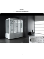
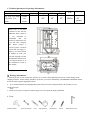
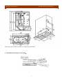
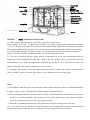
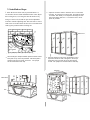
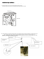
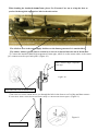
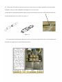
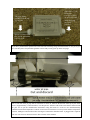
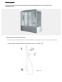
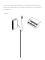
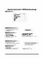
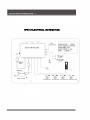
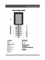
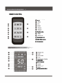
ASPEN
CARIBBEAN
INSTALLATION MANUAL
INSTALLATION MANUAL
0
Thank you for choosing the Aquapeutics Caribbean
Aspen computerized steam shower /
whirlpool bath. Please read the following manual in its entirety before assembling your
unit.
It is also very important to follow the safety suggestions outlined below at every
use.
1. Please keep in mind that like most shiny bathroom surfaces when they get
wet they may become slippery. Take care not to slip or fall.
2. Children should only use this product under adult supervision.
3. Users who suffer from heart disease or have high blood presser should
exercise greater care when using this product.
4. Senior citizens, pregnant women and those who are of ill health are
advised to get a doctors opinion on the recommended frequency of use of
this product.
1
1. Technical parameters & package information
Electrical data
Circuits
Power
1@ 110V 11.8 amps
1 @ 220V 13.6
amps
1300W
and
3000W
frequency
Dimensions (inches)
Length
Width
Height
N.W
capacity
50~60Hz
60"
63.8
34"
63.8
87"
87
390 lbs
lbs
390
40
55 Gal
gallons
Please note: If you have
purchased a Tub with the
additional heater option it
is very important to
understand
that
the
electrical requirements for
your unit have changed.
The heater requires a
second separate electrical
circuit that can supply 13
amps at 110 volts with GFI
in addition to what your
tub had originally needed.
Installation instructions for
your optional heater are in
the installation section of
this manual.
1.2
2.) Package information
1. Upon the arrival of your Aquapeutics spa take care to make a thorough inspection for any visible damage to the
shipping container. Visible damage should be reported to your carrier immediately. All SHIPPING DAMAGE should
be noted on the assigned shipping document.
2. It is recommended that all rough plumbing and electrical work be completed before the assembly of your
Caribbean
Aspen begins.
3. At least two people are required to lift the larger pieces into position during installation.
4. Tools:
Wooden mallet
open end wrench
level
Tape measure
2
Screwdriver
Pencil
4mm Hex wrench
Installation instructions
Rough Plumbing & Electrical
Drain pipe can be offset as much as 6 inches from tub drain.
2.2 Installation drawing for waste plug:
3
Upper Rail
Lights
Speaker
Shower pole
Handheld Shower
Handheld Shower
Roof Cover
Fan
Towel Pole
Mirror
Faucet Controls
Accupressure Jets
Water Connection
Shower hose
Foot massager
Soap Box
Screw Cap
Bathtub
MODEL: Caribbean
Aspen
Aspen Installation instructions:
A、Water supply: Hot and cold water supply lines are half inch NPT pipe thread
Power supply:A 220Volt,13 amp service with GFI is necessary to energize the steam room-spa and a
110 volt 11.8 amp circuit with GFI is needed for the whirlpool bath. Please note: If you have purchased a
Tub with the additional heater option it is very important to understand that the electrical requirements
for your unit have changed. The heater requires a second separate electrical circuit that can supply 13
amps at 110 volts with GFI in addition to what your tub had originally needed.
B、The size of breakers and wire gages needed is determined by local, state and national codes as
interpreted by the installing electrician. The length of the wire going to the steam generator from the
wall should be 5 feet, while the length of the telephone line needed is 7 feet. This allows the unit to be
pulled out from the side walls if maintenance is ever needed.
C、Drainage: The diameter of the drain pipe needs to be at least 2 inches. The position of the drain hole
can be within 6 inches from the hole shown in the drawing on the previous page. It is also very
important that the drain line not have a trap. It must be a straight drain line, as the shower-spa has its
own built in trap for your convenience.
Notes:
(1) The distance from the top of the steam room to the ceiling of the area where it is installed should be
4 inches or greater. (The room should be at least 4 inches taller than the spa.)
(2) It is recommended that the water pressure be at least 43 PSI and both the cold and hot water pressure
should be as equal as possible. If the pressure is lower than required, have your plumber install the
necessary equipment to increase the water supply pressure.
(3) Please have ground fault interrupter (GFI) protection on all power supply lines to the spa.
(4) It is easier to line up all panels with the hardware loose. During initial assembly please attach all
fasteners loosely, then when the unit is completely erected, snug up all bolts and screws.
4
3. Installation Steps
3.
the eccentric
allowfixed
the door
to roll
and seal
①Adjust
Connect
the leftrollers
and toright
glass
walls
(2c)
smoothly. By turning the eccentric wheel
roller the wheel is raised
ortolowered.
This allows
you to aluminum
adjust the ridecurved
height ofrails
each
the upper
and lower
side of the sliding glass door. You want the door to be as
plumb as possible.
1. Place the shower floor unit (as pictured below 1a)
16-24 inches from its final installed location. Now adjust
the leveling feet (1c) to bring the unit flat and level by
using a 3 foot level (1b) and an open end or adjustable
wrench to turn the adjusting nuts. This will raise or lower
each corner as needed. Once the unit is level and flat lock
(2d) by using 8 pieces 3/16 x 1 ¼ inch (2a)
screws with the plastic chrome spacer in
each leg into position with its locking nut.
between the curved rails and the vertical side
channel. As shown in figure 2.1
1b
1a
Figure2.1
Figure1
1c
②Use 4 pieces 3/16X ¾” screws (2e) to connect
the roller track cover (2f) with the upper and
2. The fixed glass wall (minus the sliding glass
door)
must
be the
assembled
first before
it steam
is installed
leveling
whirlpool bathtub
place the
shower
2. After
back plate on top of the tub perimeter. Affix back plate to
to the tub. Take care when inserting the glass
whirlpool tub using 6 number 30 screws. Two people
components
into the
aluminum
channels. The
are recommended
for this
step.
Fixed glass component installation diagram (Figure
2) is below. Please insert the rubber gaskets
between the glass and aluminum channels where
indicated.
2g
Back Plate
2b
2f
2e
2d
2b
Chrome spacerGlass Door
2a
Move the
glass rails.
door frame
onto the bathtub top and
4. lower
inside
(Figure2.2)
tighten the aluminum side of the glass to the acrylic
back plate using 4 number 20 round head tapping
screws. Two people areFigure
recommended
2.2 for this step.
2g
③ According to the arrow tips direction, insert the
left and right side corner aluminum extrutions
(2g) into the fixed glasses to complete the
2c
Figure2
2c
curved fixed glass wall (Figure 3).
2h
Tub
2f
2d
Figure 3
The glass walls are framed by the curved rails on
the top and bottom and with the aluminum
extrusions to the left and right.
5
Installation steps continued....
3. Steam room installation diagram, as follows (Figure 4)
5. Place the shower cover on top of the back plate and glass door frame.
Secure the shower cover to the top of the steam shower using 6 number 20 screws.
Figure 4
Shower Cover
Back Plate
Once
theall
steam
shower
fully assembled
hoses
to and has
frombeen
the steam
generator and all screws have been tightened apply a bead of marine grade silicone
6. Connect
Remove
5mm
adhesive
tape
and
(not
provided)
along
all the seams
steam shower.
screws
have been
tightened
apply inside
a beadthe
of marine
grade Do not use the steam shower for at least 24 hours after applying
silicone.(not
After
24 hoursalong
test the
shower
for inside
any leaks
where the silicone hasn't been applied thoroughly and then repeat the
silicone
provided)
all the
seams
the steam
shower.
Do not
use steam shower for at least 24 hours after
steps where
needed.
applying silicone. After 24 hours test the shower for any leaks
where the silicone hasn't been applied thoroughly and repeat
above steps where needed.
6.7. Connect all hoses to and from the steam generator. The appropriate outlets and inlets are labeled in the diagram below. The
steam generator drain hose is pushed onto the fitting (straight or elbow) connected to the steam generator. It is
secured to
this fitting by a clamp and a 3/16 X 5/8 inch round head fastener as is shown in the below diagram. The steam
generator drain line needs to be plumbed to main drain.
Steam Outlet
①Using ¼ x 1 inch bolts (3a) connect the left and right small panels(3b,3c) to the middle panel(3d)
Cold water feed
respectively
connector
to complete the whole back panel of your steam shower (3e).(Figure 4.1)
Electrical Feed
Steam Drain
Steam Generator
Figure 4.1
3e
When bending the insulated steam hose, please Use Extreme Care not to crimp the hose as
you feed it through the appropriate hole in the tub section.
Photo is not of Caribbean. But connections are the same. The placement of
components may be different.
The all silver hose is the water supply feed hose to the Steam generator. It is attached here
The rubber washer (gasket) that is secured by a wire tie is inserted into the end of Steam hose
④ Connect the insulated black high temperature steam pipe, which is on the steam outlet, to the steam
jet’s connector on the spa’s back panel. (Figure 10)
Black insulated high temperature
steam pipe
Figure 10
Front and side view of Steam outlet
⑤The water hose for the rainfall shower goes through the hole in the shower roof /ceiling and then connect
it to the elbow fixture of the shower head with a clamp as is shown in the below figures. (Figure 11)
Figure 11
Rainfall shower hose
⑥
Please refer to the labels (with icons) on the wires of the various low voltage components. They may include
Telephone, CD player/ radio, loudspeaker, LED lights, fan, control
panel
and the ozonizer O3 shower self cleaner.
and control
panel.
Connect the wires sharing the same labels and/or properly mated connector pairs. The radio antenna will need to be
unrolled and placed for best reception. See figure 12.
Figure 12
16. Connect the hot and cold water hoses, the red one is for hot water, while the blue one is for cold. Both the hot
and cold water supply lines are half inch NPT pipe thread.
This wire when
coming from the tub
is 110 volts.
This side is fed and
connected by your
electrician,
110 volts to power
the tub or 220 volts
when energizing
the steam
generator.
When it comes from
the steam generator
it is 220 volts.
If you have purchased the optional tub water heater the following image and instructions are for you. If you
have not then please skip and disregard this section and you may pick up on the next page.
Pick a side wall water jet pipe that is convenient to work on. Measure the distance taken up by the water
heater. (Approximately 7 and 5/8 inches). Cut this part out. Glue the ends of the water heater and wait until
the glue sets as per the manufactures instructions. Plug the heater in. It has its own thermostatically
controlled on/off and temperature controls. It will turn on when there is water present and the temperature
is below 102degrees and will shut off at 104 degrees. Remember that this heater is plugged into a separate
GFI 110 volt circuit as discussed in two other sections of this manual.
Silicone application
While your Aspen steam shower is still 16-24 inches away from its final installed position all joints and seams should
be calked with a high marine grade silicone sealant. (not provided) After fully testing the unit you may slide it into its
final
installed
position.
While
the Caribbean
shower
Spa is still 16-24 inches away from its final installed position all joints and seams
Aspen
steam
shower
should
be calked with a high grade silicone sealant. Then fully test the unit. Then slide it into its final installed position.
Figure13
4. Spray and foot massage installation
4.1 Connect the hose of the hand-held shower head (B) by screwing it into nozzle (A ) as depicted below
and, then put the hand-held shower head into its cradle. (C)(Figure 14)
Figure 14
4.2 Use the same technique to install the foot massage unit. Its nozzle is located approximately 16 inches below the
right side (as you enter) hand held sprayer nozzle. When using the foot massager open the cover of the unit as depicted
in the illustration below.
Figure 15)
The 5 way selector switch can send temperature
controlled water to the tub, foot massage,
hand-held shower head, the rainfall shower, or the
back message jets.
5a1
5a
When the dial (5a1) has the hand-held shower
selected, as noted by the icon, water will come out
of the left shower head.
When control knob (5b) is opened then both
hand-held showers will work.
5a2
5c
5b
OFF
38
When the selector dial is in the body massage
position water comes out of the left body massage
jets. When control knob (5c) is opened then both
sets of body massage jets will work.
Knob (5a3) adjusts the temperature of the water
and knob (5a2) is used to adjust the amount or rate
of the water entering the spa.
The five way selector (5a1) may be set to and from
any position even with the water running
ON
45
5a3
50
°C
35
30
Attention: Within your warrantee period please do not break the seal on the electrical box
or the steam generator. Doing so will void your warrantee. There are no user serviceable
parts inside. DO NOT repair or replace these units on your own.
If you do experience
any problems, please contact Aquapeutics’ Toll Free Customer Service line 1 (800)
290-6812 for after-sale service.
ASPEN OPERATION MANUAL
control panel
diagram
accupressure jets
Steam
generator cleaner
Overhead light
Exhaust Fan
Radio
Alarm
Steam Generator
Maximum radio volume: 20 decibals
68-131
Temperature range: 20-55
C degrees
Steam time:
5-50 minutes
Steam Generator
BF600 ELECTRICAL SCHEMATICS
BF600 CONTROL PANEL
LCD Panel
Accupuncture Jets
Overhead light
Radio station memory
Function button
Steam generator cleaning function
Power light
REMOTE CONTROL
Power
Function button
Accupuncture Jets
Radio station memory
Overhead light
Radio station
Radio frequency
Steam generator cleaner
To turn the power on press the
icon from the control panel or remote control. To turn
press
Thisoff
will turn
on
the overhead light as well as display the room temperature, time, and overhead light icon on the display.
Press
the
icon again.
again to shut down.
Accupuncture Jet
Jet Operation
operation
The Aspen accupuncture jets offer a series of options. The lower jets and upper jets can be operated
independently or simultaneously depending on your
thepreference.
number of times
See diagram
you press
below:
the accupuncture jet icon.
Press
Once
First press
Press twice
Second
Press
Third Press
Upper Nozzles On
Upper nozzles off
Lower Nozzles off
Lower Nozzle On
Fourth Press
Upper and
Upper
andLower
Lower
Operate
Alternate
Independently
Upper and Lower
Turn Off
5th Press
3. Steam Operation
press
Turn
Turncontrol
controller
panel
onon
and
then
press
key on control panel or remote control. Once button is depressed
you will see the steam icon appear on the control panel. Water will begin to fill in the steam generator
and the room temperature will be displayed on your control panel. The steam setup time automatically
defaults to 45 minutes and the temperature automatically defaults to 45 degrees celsius. If there is
no water running to the steam generator then the LCD screen will indicate a lack of water. If this happens
press the steam icon again to shut off. After
One
theminute
steam after
function
the steam
is shut has
down
been
the shut
solenoid
off the
valve
solenoid
steam
will valve
generator
will automatically drain any excess water from the steam basin.
4. Steam duration and temperature setup
While the control panel is on, press the
key on the panel to increase or decrease the steam time
keeping in mind that the default time is 45 minutes.
tem
To
time
key to increase or decrease by one degree celsius.
Toadjust
adjustthe
thetemperature
temperatureclick
clickthe
on the
continuously
and hold the
for 1.5 seconds to adjust the time automatically
ranges from 5-50 degrees celsius.
and continuously.
5. Exhaust Fan
5.When the panel is on, press the
again to turn off.
Press
The temperature
key on the panel or remote control to start up the exhaust fan. Press
6. Clock instructions
To adjust the time press the "FUN" key for 1.5 seconds and the time icon will flash on the display.
When the time icon begins to flash press the hour icon
to change the hour and press the
to adjust the minutes.
7. Alarm
key on the panel or remote control. and the speakers will
When there is an emergency, press the
give off an alarm sound. The alarm will also sound when there is something wrong with the system. When
this happens there will be an EE message on the LCD screen. To turn off the alarm you must turn on the
overhead light and exhaust fan at the same time and make sure all other functions
are turned off. Only then can you disengage the alarm by pressing the on/off icon.
8.
9. Overhead light
When you turn the steam shower on the overhead light will turn on automatically. To turn off simply touch
the overhead light icon on the display or remote.


![T9000E [obsolete]](http://vs1.manualzilla.com/store/data/005920932_1-890f13b4deb2f1c3de1d3a852a7c64ca-150x150.png)