1
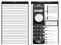
Warranty Information
This warranty covers substantial defects in materials and workmanship in the T9000E
Wireless Throttle.
What This Warranty Does Not Cover
This warranty does not cover any problems which result from improper operation, leaking
batteries, modifications or damage caused by exposure to moisture and rain. Normal wear
and tear are also not covered. Items subject to wear and tear include battery clips, the
removable antenna, antenna mounts, and the speed control.
Leaky Batteries Will Destroy The Throttle
v1.3 December 11, 2005
Ô
EASYDCC Wireless Throttle
Model T9000E
Battery installation and battery type precautions . . . . . . . . . . . . . . . . . . . . . . . . . . 2
Throttle control locations and general descriptions . . . . . . . . . . . . . . . . . . . . . . . . 3
Setting up the T9000E throttle . . . . . . . . . . . . . . . . . . . . . . . . . . . . . . . . . . . . . . . . 4
The display and wait symbol information . . . . . . . . . . . . . . . . . . . . . . . . . . . . . . . 5
Always remove batteries from an unused throttle. If the battery leaks on to the circuit
board, the throttle suffer damage that can not be replaced. The warranty does not cover
leaky batteries.
Entering a locomotive address . . . . . . . . . . . . . . . . . . . . . . . . . . . . . . . . . . . . . . . . 6
Warranty Duration
Quick Stop, Changing Speed Steps. . . . . . . . . . . . . . . . . . . . . . . . . . . . . . . . . . . . . 7
The coverage of this warranty lasts for 1 year.After this period, standard repair rates apply.
Speed display and Function control keys . . . . . . . . . . . . . . . . . . . . . . . . . . . . . . . . 8
Need Help?
If you have questions or need help, use the phone number below. In some cases, we will
busy helping other customers or it will be after hours. Please leave a message. Be sure to
leave both daytime and evening numbers along with your city and state. Have your manual
and equipment nearby before you call.
Do not send items to us for repair without first obtaining authorization. In many cases,
problems are easily solved via phone or email without the need or expense to return items
to us. If we authorize and request you to return an item, be sure to mark the “Return
Material Authorization” (RMA) number on the outside of the box. Items sent without an
RMA will be refused and returned at your expense. You are responsible for all shipping
charges.
Restore factory defaults . . . . . . . . . . . . . . . . . . . . . . . . . . . . . . . . . . . . . . . . . . . . . 9
Working with the throttle’s memory . . . . . . . . . . . . . . . . . . . . . . . . . . . . . . . . . . . 10
Controlling accessory decoders . . . . . . . . . . . . . . . . . . . . . . . . . . . . . . . . . . . . . . . 13
Changing transmit frequency, frequency table . . . . . . . . . . . . . . . . . . . . . . . . . . . . 14
Transmission mode detailed explanation and options (scan or burst) . . . . . . . . . . 15
Operating tips . . . . . . . . . . . . . . . . . . . . . . . . . . . . . . . . . . . . . . . . . . . . . . . . . . . . . 16
CVP Products 415 N. Bowser, Ste. #101, Richardson, TX 75081
C
FC
T9000E Cheat Sheet (suitable for lamination) . . . . . . . . . . . . . . . . . . . . . . . . . . . . 19
Your T9000E throttle is carefully designed and certified unlicenced low-power transmitter. The
FCC ID label and the compliance label serves to show the FCC has authorized this transmitter. This
transmitter has been tested and found to comply with the limits for a Class B digital device, pursuant
to part 15 of the FCC rules. These limits are designed to provide reasonable protection against
harmful interference in a residential installation. This equipment uses and can radiate radio
frequency energy and, if not installed and used in accordance with the instructions, may cause
harmful interference to radio communications. However, there is no guarantee that interference will
not occur in a particular installation. If this equipment does cause harmful interference to radio or
TV reception, which can be determined by turning the equipment off and on, the user is encouraged
to try to correct the interference by one or more of the following measures.
- Reorient or relocate the receiving antenna;
- Increase the separation between the T9000E transmitter and the TV/radio receiver.
FCC Licence ID: OKWTX904
24
Troubleshooting, general care of the throttle . . . . . . . . . . . . . . . . . . . . . . . . . . . . . 18
CVP Products P.O. Box 835772 Richardson, TX 75083-5772
972-238-9966 10AM- 4PM Central Time, Weekdays
www.cvpusa.com
T9000E Command Summary and Index. . . . . . . . . . . . . . . . . . . . . . . . . . . . . . . . . 23
Warranty and repair information. . . . . . . . . . . . . . . . . . . . . . . . . . . . . . . . . . . . . . . Back
WARNING - REMOVE BATTERIES
Remove all batteries from the throttle when not being used. Batteries
can leak and damage and or destroy the throttle. If the batteries leak
onto the throttle circuit board it can not be repaired.
EasyDCC, the stylized EASYDCC name, T9000Eand the logo are registered trademarks of CVP Products. © 2005
T9000 Command Summary and Reference
Installing Batteries
Antenna
+
AAA Battery
+
+
AAA Battery
AAA Battery
+
AAA Battery
First, unscrew the antenna and set it aside. If your
throttle has a shipping screw still attached at the
bottom, remove it.
The internal circuit board is attached to the
faceplate. So, just like pulling your foot out of a
shoe, slip a fingernail into the opening at the face
plate’s bottom corner (the end nearest the power
switch) and pull the plate up and out of the box. If
the plate seems too tight, use a small screwdriver
to gently pry up the plate at the bottom corner,
between the plate and the box. .
The battery orientation is marked on the circuit board. Note the batteries all face the same
direction with the plus end towards the bottom, away from the antenna.
The T9000E uses up to four AAA-size batteries. The throttle will operate on a single
battery. However, for longest life, use 4 batteries. The longest life comes from Alkalinetype batteries. For best results, use batteries having a paper cover. The battery clips are
staggered so the clips don’t touch. The clips are somewhat springy and brittle. Squarely
snap the batteries into the clips.
Warning: some inexpensive batteries are covered with a very thin layer of
paint. This paint is easily scratched when the battery is snapped into the
battery holder. If this occurs, the battery can be shorted out and the throttle
will not function properly. Shorted batteries become hot. Feel them before
closing up the throttle.
Slip the face plate back into the box. Make sure the antenna connector is completely seated
in the hole. Screw the antenna on finger tight. Do not over tighten or you risk damaging the
antenna connector. The shipping screw is not necessary.
Removing Batteries Use a dull plastic or wooden object to gently pry the batteries up and
out of the holder starting from the outside and working towards the center. Do not use sharp
objects or there is risk of scratching and damaging the circuit board. Do not bend the
contact ends of the clips or they will break off.
Using Rechargeable Batteries Rechargeable Nicad batteries may be used along with an
external charger. The newer Nickel-metal Hydrides (NiMH) cost a little more but have
none of the annoying characteristics of Nicad batteries. Be sure to use at least one AAA size
battery. Most Nicad chargers will charge the Nickel-metal Hydride batteries. However, for
best results and the fastest recharge, always use a charger designed for the specific type and
chemistry of the rechargeable battery used.
2
# nnnn #
Enter or recall from memory, locomotive number, Ln ................... 6
# DIR, n
n=1
n=2
n=3
Set Speed Steps ............................................................................... 7
14 speed steps
28 speed steps
128 speed steps
DIR
Change direction of locomotive...................................................... 6
n
Control function n where n is 0 to 9 ............................................... 8
SHOW 0, n
n =0
Show speed number and direction .................................................. 8
Set speed to 0
SHOW 1, x
x = DIR
Show memory and select any locomotive, Ln ............................... 10
Show stored speed and direction of displayed Ln
SHOW 2, x
x=#
x = DIR
Show memory and delete locomotive, Ln, direction ...................... 11
Delete displayed Ln
Show stored speed and direction of displayed Ln
SHOW 3
Show ID number (1 to 99) .............................................................. 5
SHOW 4
Show emergency-stop mode (0 = Loco, 1 = System) ..................... 4
SHOW 5
Show transmission frequency number (0 to 7) ............................... 4
SHOW 9
Show platform and software version number ................................. 14
OPR, n
n=1
n=2
Duplicates two of the SHOW commands otherwise, not used ....... na
Same as SHOW 1
Same as SHOW 2
SPR
Quick Stop....................................................................................... 7,9
SEL 0, n
Set ID number where n is from 1to 99............................................ 4,15
SEL 1, n
Set transmit frequency - Standard - where n can be from 0 to 7..... 14
SEL 2, n
n=0
n=1
Select transmission mode, scan or burst ......................................... 15
Scan mode - continuous transmission, dedicated frequency
Burst mode - intermittent transmission, shared frequency
SEL 3, n
n=0
n=1
Set Emergency Stop Operations ..................................................... 9
Stop only the active locomotive
Stop the entire EasyDCC System
SEL 4, #
Update displayed Ln’s memory ...................................................... 11
SEL 5
# nn #
1:
2:
Enter Accessory Decoder Control................................................... 13
n = accessory decoder address from 1 to 99
1 = Reverse/Off
2 = Forward/On
SEL 9, #
Clear memory and reset T9000 to factory defaults......................... 9
23
Notes
The T9000E Wireless Throttle
Tx
The liquid crystal display, LCD,
should not be pushed, pressed or
scratched. Excessive pushing on
keys or the rotary encoder may
result in image smearing.
Excessive heat can temporarily
cause the display to turn black. It
will return to normal appearance
in a few minutes after the heat
source is removed.
Rotary Encoder
Speed or Scroll Control
Push Down for Direction Key
All keys, including the direction key are
click style keys. Push and release
them”smartly” to avoid duplicate
entries. Always push and release a key
unless instructed otherwise.
Show Key
Emergency stop
selectable - loco or system
Not Used
Reserved for future use
Select/Set Key
“Pound” or Enter Key
Star, Escape or Quit Key
Power Switch - Slide Type
Left is off, right is on
22
3
Setting Up The T9000E Throttle
Notes
Before putting the throttle to work on your layout, you must select and set into the throttle
several options - some of which might be new to you. The setup requires a few keystrokes
that take effect immediately and are remembered when the power is turned off. This
section highlights the key items to set up plus provides a reference page, shown in [ ]
brackets, for more information. These settings may be changed at any time.
SEL 1
Select Transmission Frequency [ page 14 ]
The default frequency is 0. To change the frequency, push and release the SEL
key, then push the 1 key. The antenna symbol flashes indicating you are
selecting a frequency.
The available frequencies are numbered from 0 through 7. Push the desired number
followed by the # key to set the transmission frequency. It will be remembered even when
the power is turned off.
SHOW 5
SEL 2
Confirm the frequency using the key
sequence SHOW 5.The display will show
the antenna symbol and Fr: followed by the
stored frequency number which is 3 in this
example. Push * to exit SHOW mode.
Tx
Select the Scan or Burst Transmission Mode [ page 17 ]
The default mode is SCAN mode. To change the mode, push and release the
SEL key, then push the 2 key. The display shows the word OPS as a reminder
that you are in selecting the operating mode of the transmitter.
For SCAN mode, push and release the 0 key followed by the # key. You will see Scn appear
momentarily in the display indicating you are in the scan transmission mode. The display
will also show the initials TX as a reminder that you are in the scan mode.
For BURST mode, push and release the 1 key followed by the # key. You will see “Bur”
appear momentarily in the display indicating you are in the burst transmission mode. The
display will change to a blinking TX..
Confirm the transmission mode setting by checking
whether the TX is on solid (scan) or flashing (burst).
SEL 3
Tx
Select Emergency StopAction [ page 9 ]
The default action is to only stop the locomotive controlled by the throttle when
the SPr key is pressed. You can change this to halt the entire EASYDCC system.
Push SEL followed by the 3 key. The display will show ES as a reminder you are setting the
emergency stop action. For the locomotive only to be affected, push the 0 key followed by
the # key. For the entire EASYDCC system to be halted, push the 1 key followed by the # key.
SHOW 4
4
Confirm the Emergency stop setting using
the key sequence SHOW 4. For this
example, the selection is 0, or only the
locomotive is to react to Emergency stop.
Push * to exit SHOW mode.
Tx
21
Setting Up The T9000E Throttle
SEL 0
continued
Select Throttle ID number [ page 17 ]
The default ID number is 63. However, every wireless throttle, old style or new
style must have a unique ID number. This ID number may be any number from
1 to 99. However, if you are using Burst Mode, special rules apply to the
selection of the ID number. Please see page 17 for a table of “burst-mode” IDs if
you intend to use the throttle in the burst mode.
To change the ID number, push and release the SEL key followed by the 0 key. The display
shows Id to indicate you are selecting the ID number. Now push the keys for the desired ID
number followed by the # key. Leading zeroes are not required. The ID number is
remembered even with the power off.
SHOW 3
Confirm the ID using SHOW 3. The display
shows the current throttle ID number you
just entered which is 8 in this example. Push
* to exit SHOW.
Tx
The “Normal” Or Run-Mode Display
T9000
Cheat Sheet on
Opposite Side
Before jumping into lots of detail, take a look at what is called the normal run-mode display
which is abbreviated to simply “normal display.” This “normal display” is the default
display after turning on the throttle. It is also what you see after you conclude a command
or after you push * to exit the SHOW mode.
Ln is the abbreviation for Locomotive Number which is the decoder’s address. This is the
current active locomotive decoder’s address that is being controlled. If you are using
consists, this will be the consist number which is typically the lead locomotive’s address.
See the Command Station manual for how to build consists.
The direction setting is shown by the black arrow. A right arrow always meaning
FORWARD, relative to the locomotive’s cab. A left arrow means REVERSE, relative to
the cab.
The little apostrophe symbol is the speed ste p indicator. It has three segments that show the
current speed step setting and will be explained later.
Speed Step Setting
Wait Symbol
Transmit mode indicator
Direction Setting
Tx
The Active Locomotive
number (address)
Locomotive Number
The WAIT Symbol
The WAIT Symbol
The little envelope symbol
in the upper left corner of the LCD, indicates you must
WAIT. It is called the WAIT symbol or icon. While
is showing, do not use the throttle.
This symbol will turn off after approximately 2 to 3 seconds which is your signal that the
throttle is ready for use. The WAIT symbol appears after any kind of change to the throttle
such as changing the locomotive address, frequency or memory recall. Do not use the
throttle until the symbol has turned off.
20
5
When specific command sequences are described, the key or keys used are
shown in the black banner in a white rectangle. For example, the keys # nnnn #
are used, where nnnn are the one- to four numbers of the address being entered.
# nnnn #
Entering a Locomotive Address
This is simple. Push the # key, the address numbers and then the # key again. Entering a
new address, or locomotive number always starts and ends with the # key. For the
following example, the locomotive number will be 4129.
Start by pushing the # key. Notice the previous number
goes away and the small colon is now blinking. Because
of its small size, the blinking colon may be difficult to
see.
Now push the number keys, 4,1,2 and 9. The display will
show each number as it is pressed, with previous
numbers moving to the left. If an incorrect number is
entered, just continue and enter the proper 4 digits, ; no
need to start over because only the last 4 entries are
used when the # key is pushed.
Now push the # key to tell the throttle you are finished
entering numbers.
Tx
Tx
Tx
Notice the WAIT icon turns on and stays on for about 3
seconds. Do not use the throttle until the WAIT icon is
off.
Once the WAIT icon is off, the new address becomes
effective and the direction is set to forward. If you could
see the flashing colon, you’ll notice it is off too.
Tx
Controlling Speed and Direction
Speed control is with the big knob. Turn the knob clockwise to increase the speed of the
locomotive. Turn the knob counter-clockwise to decrease the speed. The speed control is a
continuously turning rotary encoder. But, unlike some speed controllers, it does not use a
center-off position. Turning the speed control clockwise, increases speed until the
maximum value is reached. Turning the control counterclockwise, decreases speed until
the minimum value is reached.
Direction control is a push switch built into the speed knob. Push down on the knob’s top
and release it to change directions. Notice the direction arrow changes.
A right facing direction arrow indicates FORWARD relative to the locomotive’s cab. A left
facing direction arrow indicates REVERSE direction, relative to the cab. The direction
arrow does not indicate the physical direction of movement.
6
EASYDCC T9000 Commands
Add/Run Loco (address nnnn)
Set Speed Steps (16,32,128)
Quick Loco Stop
Functions 0-8
Show Speed/direction
Quick Stop
Exit show speed
Select Memory Loco
Store Ln Run Changes
Delete Memory Loco
Cancel/Escape
# nnnn #
# , DIR, 1/2/3
SPr
0-8
SHOW 0
0
*
SHOW 1, #
SEL4
SHOW 2, #
*
Accessory Control
Enter address (1-99)
F1
F3
Exit, quit
SEL5
#, nn, #
Off, Reverse
On, Normal
*
Select Standard Freq (0-7)
SEL1, n, #
Select SCAN Mode
SEL2, 0
Select BURST Mode
SEL2, 1
Reset to factory defaults
SEL9, #
Show software Revision
SHOW 9
Select ID (1-99)
SEL0, #
Select ESTOP= Loco
SEL3, 0
Select ESTOP= System
SEL3, 1
Show ID
SHOW 3
Show ESTOPmode
SHOW 4
Show Transmit Freq
SHOW 5
TX symbol solid
SCAN
TX symbol flashing
BURST
Speed Steps: 16
32
128
Cut out this handy cheat sheet and laminate it for quick reference
19
Troubleshooting
Quick-Stop
Remember B - A - I - M
If your T9000E doesn’t seem to be working, or is working poorly, use the acronym BAIM
as a quick checklist. Don’t forget that the placement of the radio receiver has a large impact
on the reception. See the manual that came with your wireless receiver for more details on
receiver replacement. And finally, jamming can come from external transmitters can be
intermittent or continuous. Be aware that intermittent operation of a single throttle may be
due to jamming from an external source.
Depending on your initial selection for this command, pressing the SPR key will either halt
the locomotive or the entire system. The default and the most commonly used selection is
to stop the locomotive. Pushing the SPR key, instantly transmits the 0 speed command, to
the locomotive independent of it present speed setting. This is called the “Quick-Stop”
command.
B = Battery
Are the batteries oriented properly? Double check orientation. A reversed battery will short
out its adjacent battery and quickly run both down. The two batteries will also become hot
to the touch. If this occurs, remove and discard all batteries and install fresh batteries.
Are the batteries weak or dead? If the display is blank, replace the batteries.
A= Address
Look at the display. Did you key in the correct address. Sometimes a key will give two
entries instead of one or it was hit so quickly that it was missed. Key in the correct address
again. Push each key firmly and smartly. Don’t press and hold a key when entering
addresses. Just push and release each key, one at a time.
I = ID number
Check the ID number. Is it correct and not a duplicate?
M = Mode
Check the transmission mode. Did you or somebody else change the mode? If you are
using burst mode and a throttle has not been set for burst mode, it will jam all other burst
mode throttles. If in burst mode, make sure you have selected the proper throttle IDs.
Care of Your Throttle
Your throttle is designed for years of trouble free use. Follow these simple guidelines to
protect and extend your throttle’s life.
Remove the batteries if the throttle is not to be used for several weeks. A leaky battery can
destroy the T9000.And there is no warranty coverage for a leaky battery.
Do not attempt to recharge alkaline batteries.
Although the speed command is now 0, the locomotive may take a few moments to come to
a stop depending on the decoder sittings. This form of emergency stop takes a bit longer but
is much less destructive to the gears and motors.
Change Number of Speed Steps
# DIR
Your throttle’s rotary speed control can be set to use one of 3 different settings to change the
speed from off to full speed. These are called speed steps although they really just change
the number of rotations needed to cover the full speed range. Setting a high number of steps
provides more precise speed control for precision switching moves. A lower number
allows quick and wide speed changes for mainline operations.
There are three speed step settings from which to select: 16 steps, 32 steps or 128 steps.
For this example, the speed step setting is now 16 steps.
This can be seen by noting the apostrophe symbol which
is showing only a small, single tip.
Tx
Press and release # key. Now press and release the
direction key. The SS in the display indicates Speed
Steps.
Push one of the 3 keys listed below for the desired speed
step selection. Notice that immediately following the
selection, the speed step symbol changes.
The # key does not have to be pushed again. The
selected step value is shown for about 2 seconds before
the display returns to the normal display.
1 = 16 speed steps
Tx
Tx
[one full turn]
Keep the throttle dry. Do not expose it to moisture, steam, chemical vapors or rain.
Tx
Do not expose it or store it in high temperature locations.
2 = 32 speed steps
[about 1 and 1/2 turns]
Clean the face plate and display with a damp cloth only. Do not use solvents or cleaning
solutions of any kind.
3 = 128 speed steps
[about 6 turns]
Do not abuse the speed control. It can be damaged through excessive lateral or vertical
force.
SPR
Tx
Use a lanyard to protect against drops. See page 17.
Do not place heavy objects on the throttle.
Do not bend the antenna. It is flexible near the tip but not near the connector.
18
7
Showing Speed Numbers
Operating Tips and Techniques
At any time, you can show the throttle’s present speed value or step number being
transmitted.
Using a lanyard protects the throttle from drops. The 4-40 shipping screw has a
matching 4-40 nut permanently mounted on the faceplate. This nut makes a convenient
point to attach a 4-40 threaded screw to which a simple lanyard can be attached. Lanyards
are usually found in office supply stores. If you attend railroad or trade show conventions,
lanyards are often given away with name badges. Next time you find some, ask for a few
extras.
SHOW 0
SHOW 0 is the command to bring up the Speed Number
display. On this display, you can see the current speed
number and direction and it updates anytime you change
the speed or direction.
Speed numbers are nothing more than a range of numbers
from 0 which is OFF, to either 16, 32, or 127 which
represent full speed.
Tx
Beware of other transmitters. There is a long list of interfering transmitters that can
interfere or jam the T9000E. See the section called “Tips for Best Transmission Range” for
more information.
Tx
Note: When set for 128 speed steps, the highest number shown is 127.
Push * to return to the normal display. In almost all cases, the * key will cancel or terminate
a command.
The decoder’s speed step setting is independent of the throttle setting and is not changed
when the throttle’s speed step setting is changed. The change takes effect immediately.
Quick Stop While Showing Speed Numbers
When in the SHOW SPEED mode, push the 0 key to instantly zero the transmitted speed
number. Although the speed is now 0, the locomotive may take a few moments to come to a
stop. This form of emergency stop takes a bit longer but is much less destructive to the
gears and motors.
Function Keys
n
The T9000E throttle supports 9 functions, F0 - F8, as currently defined by the NMRADCC standard.
Note: It is the decoder that establishes how many functions are available and supported.
Always read the decoder’s manual to determine which functions are available as well as to
their options.
If your decoder uses a function higher than supported by the T9000E, it can be assigned to
one of the lower function numbers. See the decoder manual for how to reassign functions to
the available function keys.
Functions - F0 to F8: Each of the T9000’s number keys are assigned to the respective
DCC function; the 0 key is F0, the 1 key is F1, the 2 key is assigned to F2, etc. To active a
function, push the desired number key. When a function key is pressed, the function
number appears on the display and when the key is release, it stays on for a couple more
seconds and then the normal display reappears. Except for F2, all function controls are
latching. This means that the “activate” command is sent when the key is first pushed and
released. Pressing and releasing the key a second time sends the “deactivate” command.
F2 is special and is usually assigned to a horn or whistle function. Pressing and holding the
F2 key activates the horn or whistle. Releasing F2 deactivates the horn or whistle.
8
Take advantage of different speed step settings. The T9000E has three different speed
resolutions that control how many rotations from stop to full speed. At any time you may
change the speed steps. For example, when executing slow speed switching in a yard, use
the 128 speed step setting for the finest control. If out on the main, the 16 or 32 speed step
setting is more than adequate.
The default locomotive address 2 is not automatically placed into memory after
restoring factory defaults with the SEL 9 key. If you have a real locomotive with address 2,
enter it with the usual # 2 # to make it active AND to store it in memory.
Leading zeroes are not needed. A locomotive addresses can be in the range of 1 to 9999.
And changing the throttle address can be done at any time and without turning off power.
The address change becomes available when the WAIT symbol turns off. The previously
used address is stored in memory and may be recalled at any time.
Address 0 is not allowed. If zero is entered, it will be ignored and the current address will
remain unchanged.
Throttle speed is always reset to zero after power is turned off and back on. In other
words, the rotary speed control is reset to 0 independent its setting before power was turned
off. Also, when power is turned on, the default direction setting is always forward.
The last locomotive address used is restored when power is turned on. To change to
another locomotive address, either key in the address or select it from memory.
All non-zero speed values in memory are reset to zero when power is turned on. If you
had a locomotive with a non-zero speed value in memory and turned off the power, the
throttle will instantly zero the speed and set the direction to forward.
Burst mode operation works best if the T9000E throttle has its own, dedicated
receiver. If using older wireless throttles and multiple receivers, consider assigning the
T9000E throttles to an exclusive receiver.
17
Tips For Best Transmission Range
Restore Defaults & Clear All
The T9000E Throttle operates in an unlicenced band shared by many other transmitters.
These transmitters can and will create interference, intermittent throttle operation or
complete failure of one or more of your throttle’s 8 frequencies. The sources of these
external interfering signals can be from your own home or from adjacent homes and
businesses or noisy electrical motors including your locomotive.
There are many settings of the throttle that are remembered, even if the power switch is
turned off and the batteries are removed. However, at any time, you may force the throttle
back to its original factory settings, just as you received it. When the command is issued, all
memory is erased and the defaults are reloaded.
Interfering Transmitters. Here's a list of devices known to have caused interference to
the throttle: other throttles on the same frequency, wireless devices attached to computers,
TV remote controls, cordless telephones, alarm systems, baby monitors, unlicenced
personal communication devices, lawn sprinkler controllers, remote starter switches,
cordless light switches, outdoor lighting controllers, toys, wireless headphones, and
games.
If you find a strong interfering signal on one or more of your frequencies, don’t use those
frequencies; pick a different frequency and try it..
Antenna Care. Antenna should be finger tight. It should never be loose. Never operate the
T9000E without the antenna. Keep the antenna away from metal objects. and don’t place
your hand around the antenna.
Use Fresh Batteries. Weak batteries can affect the transmission range. When the weak
battery warning indicator turns on, replace the batteries as soon as practical.
One Throttle per Frequency In Scan Mode. Do not have two throttles on the same
frequency (except if in burst mode). They will jam each other and neither will work
properly. Only one throttle may be on a frequency at one time. The throttle should be
labeled with its frequency number.
Wait for the to turn off. Teach operators to not use the throttle until the little envelope
symbol, which is the WAIT icon, is turned off. Attempting to use the throttle can result in
unpredictable operation. Please wait for the symbol to turn off before using the throttle.
Compatibility with RF1300 and TX904
The T9000E works alongside the older RF1300 and TX904 wireless throttles without any
changes or modifications to the older units. Do make sure that all throttles are given a
unique ID number. Also make sure the throttles are on appropriate frequencies for their
transmission mode setting. Make sure to have the latest software in the older throttles.
Burst mode in the T9000E works much better than the burst mode in the RF1300 and
TX904 as long as you use the recommended burst ID numbers in the T9000E. The best
burst operation occurs when only T9000E throttles are used and are not mixed with the
older wireless throttles on the same receiver. If using multiple receivers, consider
assigning the T9000E throttles to an exclusive receiver.
Symptoms of burst mode jamming are slow or sluggish response, and very long times for
new addresses to be recognized by the command station. If this situation occurs, reduce the
number of throttles sharing a single frequency and add more receivers.
16
To restore the factory defaults, first push and release the
SEL key and then push the 9 key. The display will be
blinking the dEF 2 command and a small envelope will
appear in the upper left corner. All of these symbols are
to remind you that you are about to perform a reset. To
abort the reset, with no changes, push the * key.
To complete restore and clear-all sequence, push the #
key. The display instantly reverts back to the original
default normal message of Ln 2, 32 steps and forward.
The other main item that is changed is the transmit
frequency which is set to 0. The table below shows the
complete set of factory reset values.
Item
Ln Memory Slots
Transmit Mode
Locomotive Number
E-Stop
Default
Cleared
SCAN
2
Locomotive
SEL 9
Tx
Tx
Tx
Item
Functions
Transmit Freq.
Speed Steps/DIR
ID number
Default
All OFF
0
32, FWD
63
Selecting Emergency Stop Mode
SEL 3
There are two settings for emergency stop. The default setting is for the SPr key to only
stop the locomotive address shown on the display. The other setting is allows the throttle to
stop the entire system. Pushing SPr activates the command.
Push SEL followed by the 3 key. The display will show ES as a reminder you are setting the
emergency stop action.
Push 0 and # - for the locomotive only to be affected by Emergency Stop.
Push 1 and # - for the throttle to stop all locomotives and the Command Station.
Emergency Stop Activation - System Stop
SPr
If you have selected to use the E-Stop mode that halts the entire system, the Command
Station shows the message <<ALL STOP>> and the throttle shows ES 1 when SPr is
pressed. This is your clue that your throttle has initiated the system stop. Only the throttle
that initiated theALL STOP command can clear it.
Once you have pushed the SPr key to halt the system,
Tx
the other keys on the throttle are ignored. To clear ES 1
and restore normal system operation, push the SPr key
again. Cycling throttle power will also clear ES 1.
9
Recalling A Locomotive From Memory
Throttle Transmission Mode Select
If you wish to follow the example, you must reset the throttle to factory defaults as shown on
the previous page.
Your T900E throttle supports two forms of data transmission, Scan and Burst. When there
are fewer than 8 throttles, the scan mode is best. When you need to use more than 8
throttles, or you have some frequencies that are experiencing jamming problems, burst
mode offers some benefits.All of throttle features are the same.
SHOW 1
To show the locomotive address memory, first push the SHOW key followed by the 1 key.
This is shortened to SHOW, 1. You may cancel the command at any time by pushing the *
key.
To scroll through the memory, use the big knob. The starting point is always the bottom of
memory which was the 1st locomotive entered. Rotate the knob clockwise to step through
memory or counterclockwise to go to the bottom. You may scroll in either direction
through memory from bottom to top, or top to bottom. The 1st entry is always empty and
will remain so, as addresses are added. The 15th address entered will then occupy the 1st
entry.
For this example, set up the throttle with the following addresses. Enter the addresses in
this order using # nnnn #: 100, 1024, 52. Now key in 4129 and set the speed steps to 128.
These 4 locomotives are now in memory with their current speed step setting, speed value
and direction.
The first display shows 4129 which is the active
locomotive since it was the last one entered. Note the
speed step indicator which has all 3 segments on.
Push SHOW. Notice the M is on. This serves as a
reminder that you are entering into memory mode with
the next key.
Push 1. The colon and the M will flash indicating you
are now viewing the 1st entry in the locomotive
memory which is blank.
Rotate the speed knob one click to the right to view the
2nd location in memory. It will be 100.
Tx
Tx
You can switch between modes at any time. The radio receiver/basestation must match the
throttle setting. Please see the manual that came with your wireless receiver for additional
usage tips.
Scan mode is the most commonly used mode when there are no more than 8 throttles in
use. Each throttle has its own dedicated frequency and transmits continuously. This mode
provides the fastest system response time and can not be jammed by any other throttle. The
benefits are fast response time, no time delay, and no interference from other throttles.
Burst mode allows up to 8 throttles to share a single, specific frequency. The selected
frequency is set into the radio receiver and it stays on this frequency, processing all throttles
using it. When the throttle is set for burst mode, it turns on its transmitter for a short
moment and “bursts”out the data. It then turns off the transmitter and waits fixed amount of
time before bursting out again. During the quiet time, another throttle can burst out its data.
However, there is always a chance that two throttles will turn on and burst at the same time
and jam each other. The jamming can cause delays and slower response time. The T9000E
has an improved burst algorithm that provides much better response time compared to the
older RF1300 and TX904 designs. Keep in mind that as more throttles are added, the
chances of one or more throttles being occasionally jammed goes up.
You may use any ID on the throttle when in scan mode. But, when in burst mode, each
throttle should be given the specified IDs and in the sequence shown. These IDs have been
selected to provide the least amount of jamming and interference especially when more
than 5 throttles are in use.
Tx
Tx
First T9000E
Second T9000E
Third T9000E
Fourth T9000E
Push # to select the displayed address and make it the
active address. Notice that the normal display has
returned, the M is gone and the WAIT symbol is on.
Tx
ID 5
ID 19
ID 3
ID 22
Scan
Burst with 4 throttles
Burst with 8 throttles
Max # throttles in use
8 (w/1 rcvr) 28 (w/7 receivers)
56 (w/7 receivers)
Response Delay
Shortest
Longer
Longest
Allowed Frequencies
0-7
0-6
0-6
ID allowed
Any
Select from Table
Select From table
Tx
Note that 1024 is now the active address and the speed step is set at 32.. Address 4129 and
all of its settings were automatically stored in memory when 1024 was selected. Always
wait until the WAIT symbol turns off before using the throttle.
10
Fifth T9000E
Sixth T9000E
Seventh T9000E
Eighth T9000E
ID 13
ID 10
ID 4
ID 12
Summary of the Two Transmission Modes
Factor
Rotate one more click to the right to see the 3rd location
which is the desired locomotive address, 1024.
SEL 2
If using the T9000E with the Atlas/Lenz System, the highest allowed ID number is
31. Be sure to use an ID number within the range of 1 to 31 for the Atlas/Lenz
system. Also, make sure that no two devices on the Atlas/Lenz ExpressNet bus
have duplicate ID numbers and that none of the reserved ID numbers are used.
15
Replace Battery Indicator
When the batteries have reached their final few minutes
of charge, the low battery icon turns on. You only have a
few minutes remaining before the batteries are
completely exhausted and it is possible for the throttle to
cause unexpected operation during this time. To prevent
loss of control, bring all operating locomotives
controlled by this throttle to a stop as soon as possible.
SHOW 2
Low Battery Icon
Tx
Once all locomotives have been stopped, turn off the throttle and replace the batteries.
SHOW 9
SHOW 9 causes the platform and software version
number to be displayed.
Changing The Transmit Frequency
SEL 1
Each wireless throttle must be on a unique frequency so as not to jam other throttles. When
in SCAN mode, any unused frequency can be used. There are 8 standard frequencies
available for selection, numbered 0 to 7. The frequency can be changed at any time. If in
BURST mode, frequencies 0-6 may be used. Do not use frequency 7.
Push any number from 0 to 7. For this example,
frequency 4 will be selected. To confirm the new
frequency, push #. The change takes effect immediately.
14
903.37 MHz
906.37 MHz
907.87 MHz
909.37 MHz
912.37 MHz
915.37 MHz
919.87 MHz
921.37 MHz
Notice that the E and M are gone and that the normal
display has returned. If you have been following along
with this example, use SHOW 1 to confirm that 52 is
gone.
SEL 4, #
Tx
Availability
0
1
2
3
4
5
6
7
For this example, lets delete locomotive 52. Use the speed
control to scroll to the locomotive 52. When 52 is shown,
push the # key.
Tx
Tx
Tx
Tx
Tx
Tx
The following frequencies are available on the T9000E throttle using the SEL 1 command.
Note that frequency 7 is not to be used if the throttle is in the burst mode.
Frequency Number Frequency
If you have a desire to manually delete locomotives, a
command has been provided for this function. You may
scroll through memory and select any locomotive address
for deletion. You should not delete the active locomotive.
For the following example, 1024 is the active locomotive.
Notice that the E above the M is now flashing. It is a
reminder that you are editing memory and all actions are
permanent. At any time you can cancel the command with
the * key.
Tx
Push * to return to the normal display.
Push SEL and then 1. The antenna icon will start flashing
and the default frequency of 0 is shown. The table below
shows the 8 standard frequencies and their number.
If all 15 locomotive memory locations have been used, the T9000E automatically
overwrites the oldest entry upon entry of the 16th locomotive be entered. This is automatic
and you do not have to do anything to make more space.
SHOW-2 is used to manually delete locomotives from
memory. Push the SHOW key followed by the 2 key.
Show Software Version Number
9000E is the throttle platform and 1.0 is the software
version number. Your version number may be different.
Deleting A Locomotive From Memory
Scan
Burst
Yes
Yes
Yes
Yes
Yes
Yes
Yes
Yes
Yes
Yes
Yes
Yes
Yes
Yes
Yes
NO
Manual Update Of Locomotive Memory
The throttle’s locomotive memory contains a snapshot of the speed, direction, speed-step
setting and function status from the last time you either entered or recalled the locomotive
from memory. If there have been any changes that you want to save to memory, you may do
so at any time, using the SEL-4 command. The most common time you may want to
manually update the locomotive is when there has been a change in the speed steps or
function commands.
SEL-4 will update the throttle’s memory with the present settings of the active
locomotive. This command can be used at any time. To cancel this command push *.
Push SEL followed by the 4 key. The envelope icon plus
the SLn means Save-Locomotive-number 1024 status
and functions.
Tx
Push the # key to finish the command. The normal display
returns but now you have an updated copy of the current
function settings, speed and direction.
The locomotive memory for the present address is automatically updated
anytime you enter a new locomotive address.
11
The Throttle’s Ln Memory
Accessory Decoder Control
The T9000 throttle can store the speed and direction of the previous 15 locomotives used
in what is called a memory slot. A memory slot is a shorthand word to mean a section of
memory used to store a locomotive number and its associated settings such as the speed
value, the direction, the speed step setting and the status of all functions. If all slots are
used, the oldest entry will be automatically overwritten.
Accessory decoders may be controlled from the T9000E. Due to memory constraints, the
allowed address range is 1 to 99. Accessory decoders are commonly used to control
turnouts, layout lighting and other stationary functions.
Each time a new and unused address is entered with # nnnn #, the former address is
automatically stored in one of the 15 memory slots. Once stored, you may recall any
address from memory and instantly restore the throttle and its associate settings to exactly
the same condition as when you last used the recalled address.
When scrolling through the locomotive memory that does not have 15 stored locomotives,
the scroll starting point is the 15th memory slot which will be blank. This slot remains
blank until the 15 locomotive is entered. At that point, the starting point for all scrolling
becomes the 1st memory slot. Scrolling goes from 1st to last; it doesn’t wrap around.
Less than 15 locos
Ln
Start
Scroll
Ln
Ln
Ln
Ln
Ln
Blank
Etc
52
1024
110
12
Blank
With 15 locos
14th and last entry
4th Entry
3rd Entry
2nd Entry
1st Entry
15th Entry
Ln
Ln
24
33
15th and last Entry
14th entry
Etc
Start
Scroll
Ln
Ln
Ln
Ln
52
1024
110
12
4th Entry
3rd Entry
2nd Entry
1st Entry
Note: the Locomotive numbers shown are for example only
Additional Notes About The Run-Time Environment
Unlike most other wireless DCC controllers, the T9000E maintains two separate
environments, one that is active and one that is stored. The run-time “environment”
describes a set of conditions in which a locomotive is running or “active.” Environments
can be edited while stored and then recalled an made active. Once activated, all changes
become effective.
The environment is always paired with a locomotive address. The environment consists of
the following variables:
Locomotive Address . . . . . . . . . . . . . . . from 1 to 9999;
Speed Value . . . . . . . . . . . . . . . . . . . . . . 0 to Speed Step Max (16 or 32 or 128)
Direction Setting . . . . . . . . . . . . . . . . . . Forward or Reverse
Speed Steps . . . . . . . . . . . . . . . . . . . . . . 16 or 32 or 128
Function 0 through 8 . . . . . . . . . . . . . . . On or Off, except for F2
Recalling a locomotive from memory, also restores its associated environment. Storing the
environment is usually done automatically. However, if you make a change in one of these
settings, you can force a manual update of the active locomotive’s memory by using the
SEL 4 command (see page 9).
12
SEL 5
Like locomotive decoders, accessory decoders have addresses and functions which may be
controlled and programmed. Accessory addresses are different from locomotive
addresses. You can have a locomotive address 28 and an accessory address 28 without any
interference
Selecting and controlling accessory decoders is easy and you can still control your
locomotive’s speed and direction while throwing turnouts.
Push and release SEL5 to bring up the accessory decoder
control display. Acc is the abbreviation for Accessory. At
this point you will enter the address of the accessory
decoder. For this example, lets use 28.
Push and release # 2 8 #. Notice that when you push the
first #, the display changes to “Adr” show an address is to
be entered. When the ending # is pushed, two icons, F1
and F3 appear above the address. These are small and
will be flashing near the upper right corner.
The flashing F1 and F3 remind you that the “1” key and
the “3” key are used to control turnouts and/or on-off
effects such as lighting effects.
F1
F3
F1 is used to throw turnouts REVERSE or turn lights
OFF. F3 is used to throw turnouts NORMAL or turn
lights on. The appropriate icon, F1 or F3, will turn on
solid when the key is pressed. The turnout direction is not
remembered.
Addition Tips When Controlling Accessory Decoders
During the time you are controlling turnouts, the speed and direction controls will continue
to operate. However, locomotive functions are not available. Note that changing directions
will start the F1/F3 icons flashing again which is OK. The throttle does not remember
which direction the turnout was thrown.
Once you have finished with the decoder address, you may enter a new address starting
with the # key. There is no need to push SEL 5 again.
Terminate or exit this mode and return to the normal display by pushing the * key.
If you are using CVP’s accessory decoders, the address is actually the “output” number
which is in the range of 1 to 99. These numbers are not the same as locomotive numbers.
You may have an accessory decoder with output number 1 and a locomotive number 1.
There will be no conflict.
Your installation and wiring of the switch machines will determine the actual direction the
switch throws. If a turnout throws the wrong direction reverse the two wires going to the
turnout.
Accessory Decoder activation commands are transmitted once. If the transmission is
jammed or garbled, the switch may not throw. However, you can simply push the same key
again to retransmit the activation command.
13

![G2 Decoder [obsolete] Second Generation User Manual](http://vs1.manualzilla.com/store/data/005963661_1-2c18e92993151caf68904a7a924089ff-150x150.png)


![AWD10SS [obsolete] User Manual](http://vs1.manualzilla.com/store/data/005777265_1-bc3e4afb4b891fb2fe3c32a930faa0e5-150x150.png)