1
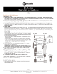
PHD User Manual
Table of Contents
Overview....................................................................................................2
Install PHD Software.................................................................................3
Connect PHD Equipment..........................................................................5
Connect Sensor to the PHD Programmer.................................................6
Run PHD Application.................................................................................7
Verify Parameters and Program Sensor..................................................10
View Output and Verify Configuration.....................................................12
Saving and Loading Programs................................................................13
Troubleshooting .....................................................................................14
PHD User Manual
Overview
BEI Sensors introduces the Programmable Hall Device (PHD), an easy way to take control of customizing BEI Hall effect sensors output. This compact system interfaces with your PC to BEI Hall effect
sensors and provides users with the ability to create output functions that meet specific requirements.
The system includes proprietary PHD software (compatible with Windows XP, 7 or Vista), the PHD
programming unit, power cord and a USB computer interface cable. Cables to interface the PHD to
specific sensor connectors are sold separately. A positions fixture is recommended if the sensors are
not programmed after installation in the final assembly
The PHD programming process uses simple 6-step procedure:
1.Install the PHD software.
2.Connect PHD equipment.
3.Connect the programmable sensor to the PHD Programmer using the Sensor Interconnect
Cable.
4.Run PHD application and create the configuration profile on a PC.
5.Verify parameters and configure the sensor by manually rotating the sensor through the
desired range of motion and selecting the programming points in the PHD application.
6.View output and verify the sensor is configured as desired.
7230 Hollister Avenue, Goleta, California 93117 | Tel: 805-968-0782 | Fax: 805-968-3154 | www.beisensors.com
Specification No.: 02135 Rev: 5-23-2013
2
PHD User Manual
Step 1: Install PHD Software
1.Insert USB flash drive provided with the PHD and install software. Desktop and start menu
shortcuts will be created.
2.Click “Open folder to view files”.
3.Right-click “setup.exe” and select “Run as Administrator”.
4.Run through PHD install and click “Next>>” until the installation is complete.
7230 Hollister Avenue, Goleta, California 93117 | Tel: 805-968-0782 | Fax: 805-968-3154 | www.beisensors.com
Specification No.: 02135 Rev: 5-23-2013
3
PHD User Manual
5.Once the software has finished installing, the PHD Drivers will automatically be installed.
6.Click “Next>” to finish the Device Driver installation process.
7.Click “Finish”. You have successfully installed the PHD software and drivers.
8.Remove the USB flash drive.
9.Restart the computer.
7230 Hollister Avenue, Goleta, California 93117 | Tel: 805-968-0782 | Fax: 805-968-3154 | www.beisensors.com
Specification No.: 02135 Rev: 5-23-2013
4
PHD User Manual
Step 2: Connect PHD Equipment
1.Connect the USB-A end of the Computer Interface Cable to the USB port on your computer.
2.Connect the USB-B end of the Computer Interconnect Cable to the USB port on the
Programmer.
3.Connect the AC Power Cord to the AC Adaptor.
4.Connect the AC Adaptor to the Programmer.
7230 Hollister Avenue, Goleta, California 93117 | Tel: 805-968-0782 | Fax: 805-968-3154 | www.beisensors.com
Specification No.: 02135 Rev: 5-23-2013
5
PHD User Manual
Step 3: Connect BEI Programmable Sensor to PHD Programmer
1.Connect the 25-pin connector end of the Sensor Interconnect Cable to the Programmer.
2.Connect the 6-pin or 3-pin connector end of the Sensor Interconnect Cable to the BEI
Programmable Sensor.
3.Plug the AC Power Cord into an outlet and move the power switch on the Programmer to the
“1”or on position. The green and red lights should be lit.
• Verify that the Windows Driver Install was successful.
A small bubble should appear alearting you that the PHD has been detected.
• Click on the bubble to bring up the following screen.
• After a moment of searching, Windows will locate the drivers and the PHD Programmer will be ready to use.
7230 Hollister Avenue, Goleta, California 93117 | Tel: 805-968-0782 | Fax: 805-968-3154 | www.beisensors.com
Specification No.: 02135 Rev: 5-23-2013
6
PHD User Manual
Step 4: Run PHD Application and create the desired program
1.Run the PHD Application. It will automatically find and connect to the PHD Programmer.
2.If the software cannot find a PHD Programmer a “No PHD Device Found!” message will
appear.
• *Note: The user can continue without a PHD Device connected to create programming
profiles for later use. If there is no Programmer connected, a “Connect to PHD?” dialog
will appear. Once you have connected the programmer, select “Connect” to continue.
3.Select the Unit Type: This is the series of BEI’s programmable sensor you will be
programming.
• *Note: Programmable versions of the 8360 and 9360 series will be available soon.
7230 Hollister Avenue, Goleta, California 93117 | Tel: 805-968-0782 | Fax: 805-968-3154 | www.beisensors.com
Specification No.: 02135 Rev: 5-23-2013
7
PHD User Manual
4.Select the Output Type: The output type is selected based on the “Unit Type” chosen in Step
#4.
• *NOTE: The desired programming will not be achieved if the incorrect Output Type is
choosen.
• Unit Type 9960–this sensor series has several different versions of programmable types.
• 0-5V Ratio – This is a 9960-5A Input/Output version, 0-5V Input for 0-5V Output.
• PWM – This is a 9960-5X2 Input/Output version, 5V Input only.
• 0-5V Non- Ratiometric – This is a 9960-9X2 Input/Output version, 9-30V Input for 0-5V
Output
• 0-10V Non-Ratiometric – This is a 9960-15X Input/Output version, 15-30V Input for
0-10V Output
• 4-20mA – This is a 9960-9X1 Input/Output version, 9-30V Input for 4-20mA Output
5.Define the Rotation Direction of the sensor. In the Rotation Direction box there are two
options, Clockwise (CW) and Counterclockwise (CCW).
•
CW– Choose Clockwise for both outputs if the desired
output slopes you are programming occur when the rotor is rotated
clockwise (when viewed from the rotor side of the sensor).
•
CCW– Choose Counterclockwise for both outputs if the
desired output slopes you are programming occur when the rotor is
rotated counter clockwise (when viewed from the rotor side of the
sensor).
6.Define the Programming Points for Sensors 1 and 2 (Sensor 1 and Sensor 2 do not have to
have the same number of programming points).
You are able to choose where in the rotational angle each of these points are as well as the
output percentage at each point. For example, 3 Point options are most commonly defined as:
• Point “A”– percentage of output at beginning of travel
• Point “B”– between Points “A” and “C”, usually midway (50%)
• Point “C”– percentage of output at end of travel
• The percentage output for Point “A” and Point “C” depends on your
needs. For proper operation the % for Points ‘A”, “B” and “C” must be
greater than the Clamp Low % and less than the Clamp High %.
7230 Hollister Avenue, Goleta, California 93117 | Tel: 805-968-0782 | Fax: 805-968-3154 | www.beisensors.com
Specification No.: 02135 Rev: 5-23-2013
8
PHD User Manual
7.Define four additional parameters for the part:
•
Hysteresis– The Hysteresis option allows you to to
independently program the amount of hysteresis each output
will have. A value of zero degrees will give the minimum amount
of hysteresis and 11 degrees will give the maximum amount of
hysteresis. This value is most commonly set to zero.
•
Travel (Deg)– The Travel option allows you to program the
rotational angle you want to resolve. Values from 1° to 360° are
valid, however the linearity of the output may be negatively impacted for angles less than
15°. It is possible to program a separate angle for each of the sensor’s outputs; however
a slightly different programming sequence from this example is required.
• Clamp Low and Clamp High– Allows you to independently set min/max percentage
limits for each output. These limits restrict each output from going beyond the limit
programmed. Clamp High and Low work exactly the same way for the Non-Ratio Metric
and PWM units as it does for the Ratiometric. For example assuming 5VDC is supplied to
the sensor’s input, the output would be as follows:
Clamp Low
(%)
Clamp High
(%)
Min/Max Vout
(V)
0
100
0/5
5
95
0.25/4.75
10
90
0.5/4.5
25
80
1.25/4
8.If PWM was selected as the Output Type two additional parameters must be set:
• PWM Frequency is the output frequency which the PWM unit will output at, this value is CONSTANT and does not change with output location.
• PWM Polarity determines how the Duty Cycle changes based on the position of the shaft.
• Rising Edge– 0% High at 0% position, 100% High at 100% position.
• Falling Edge– 0% High at 0% position, 100% High at 100% position.
7230 Hollister Avenue, Goleta, California 93117 | Tel: 805-968-0782 | Fax: 805-968-3154 | www.beisensors.com
Specification No.: 02135 Rev: 5-23-2013
9
PHD User Manual
Step 5: Verify Parameters and Program the BEI Sensor
1.Click “Verify Parameters” for either Sensor 1 or Sensor 2. This step checks to make sure that
all the needed values have been entered correctly.
•
If there is an error the software will indicate what needs to be fixed.
•
If there is no error the software will grey out the sensor under program.
2.Click “Begin Programming” to start the programming process, this initializes the chip and
prepares it for programming.
3.If you want to insure correlation between the two Sensors, select “Synchronous
Programming”.
•
*NOTE: This feature is only available if Sensor 1 and Sensor 2 have the same “Programming Points” selected.
4.Position the sensor at the desired location for Point A and click “Program A” without moving
the part.
7230 Hollister Avenue, Goleta, California 93117 | Tel: 805-968-0782 | Fax: 805-968-3154 | www.beisensors.com
Specification No.: 02135 Rev: 5-23-2013
10
PHD User Manual
5.Rotate the part in the appropriate direction (In this example Counter Clockwise) as selected
in the “Rotation Direction” field to the next programming point, Point B and click “Program B”
without moving the part from the desired position.
6.If you have selected something other than a “2 Points” programming option, repeat steps
4 & 5 for the remaining points. Otherwise, you may release the part and click “Finalize
Programming” to finish the programming process.
7.You may now repeat the process for the other sensor. The procedure is the same if you have
selected “Synchronous Programming”.
7230 Hollister Avenue, Goleta, California 93117 | Tel: 805-968-0782 | Fax: 805-968-3154 | www.beisensors.com
Specification No.: 02135 Rev: 5-23-2013
11
PHD User Manual
Step 6: View output and verify configuration
1.If you wish to verify the output of the programmed sensor select the “View Output” button on
the lower right hand section of the screen to bring up a real-time graph of the sensor output.
2.Rotate the part to observe how it’s output changes.
7230 Hollister Avenue, Goleta, California 93117 | Tel: 805-968-0782 | Fax: 805-968-3154 | www.beisensors.com
Specification No.: 02135 Rev: 5-23-2013
12
PHD User Manual
Saving and Loading Programs
Once you have selected the parameters to program you can choose to save those settings to use at
another time using the File menu in the software.
1.Select “File” in the top menu barand then click “Save” and store the file on your computer for
later use.
2.Select “Load” to open a previous saved program.
7230 Hollister Avenue, Goleta, California 93117 | Tel: 805-968-0782 | Fax: 805-968-3154 | www.beisensors.com
Specification No.: 02135 Rev: 5-23-2013
13
PHD User Manual
PHD Troubleshooting
Problem
Software Does Not Install Correctly
Software Does Not Find the Hardware
Solution
The most likely cause of an invalid installation relates to
computer security.
Uninstall the software and re-install being sure to rightclick the setup.exe file and select “Run as Administrator”
Make sure that the PHD is properly connected to the
computer and is running the software via the supplied
USB Computer Interface Cable.
Verify that the red indicator light on the PHD is lit. This
indicates that the PHD is receiving power.
Software Doesn’t See the Sensor
Validate that the Drivers installed correctly by going toStart >> Control Panel >> Device Manager. There should
be no devices with a yellow exclamation point.
Make sure that the sensor is connected correctly; reversed leads will prevent the communication process.
Sensor Programs “Backwards”
Verify that the right type of sensor has been selected.
Verify that the correct rotation direction has been chosen.
Recall: The rotation direction is defined as the direction of
rotation when viewing the sensor from the shafted side.
Sensor Programs Incorrectly
Sensor Outputs Don’t Correlate
Error Message “Part installed is not a
BEI Sensors part.”
Insure that the correct values have been selected for the
programming points.
Insure that all connections to the sensor are solid and
free of contaminates. An intermittent connection can
cause issues.
Check all programming parameters for errors.
Check that the correct sensor type has been selected and
the proper output type to correlate with that sensor
Output correlation can only be guaranteed by using the
“Simultaneous Programming” option. Even with this it is
possible for slight variations to exist.
There are a few reasons that this message may appear:
• Attempting to program a Non-BEI Part
• Attempting to program a Non-Programmable BEI
Part
• An error occurred at the factory and the part was
incorrectly coded.
If you feel this is the case, please contact BEI Sensors,
Goleta for assistance.
7230 Hollister Avenue, Goleta, California 93117 | Tel: 805-968-0782 | Fax: 805-968-3154 | www.beisensors.com
Specification No.: 02135 Rev: 5-23-2013
14