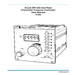
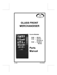
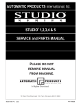
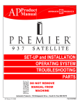
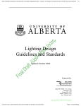
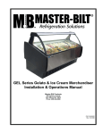
1
Emergency Ballast
Installation and User’s Manual
EMERGENCY BALLAST MODEL:
NB24-T5T8-01E
Rev. 031114
Please contact Customer Support at 1-800-24VOLTS for further information.
Copyright 2013-2014 all rights reserved by Nextek Power Systems, Inc. in the
United States and in other countries throughout the world.
Emergency Ballast
Installation and User’s Manual
TABLE OF CONTENTS
ABOUT NEXTEK POWER SYSTEMS
3
INTRODUCTION / OVERVIEW
4
1.0
SAFETY
5
2.0
STANDARDS & REQUIREMENTS
6
3.0
REGULATORY INFORMATION
7
4.0
TRAINING
7
5.0
FEATURES AND SPECIFICATIONS
8
6.0
GENERAL REQUIREMENTS
9
7.0
INSTALLATION PROCEDURE
10
7.1
EMERGENCY BALLAST INSTALLATION
10
7.2
WIRING A 2-LAMP BALLAST TO
AN EMERGENCY BALLAST FIXTURE
12
8.0
NOTES
For more information:
2
Nextek Power Systems
461 Burroughs Street
Detroit, Michigan 48202
13
Tel: 313-887-1321
Toll free: 1 (877) 24-VOLTS
Fax: 313-887-9433
www.nextekpower.com
[email protected]
Copyright 2013-2014 all rights reserved by Nextek Power Systems, Inc. in the United States and in other countries throughout the world.
Rev. 031114
Emergency Ballast
Installation and User’s Manual
ABOUT NEXTEK POWER SYSTEMS
Nextek Power Systems AC/DC integration technology represents a breakthrough in onsite electrical management, combining the availability of AC power with the quality and
efficiency of a DC supply.
NEXTEK PRODUCT BENEFITS
•
Easy conversion of AC lighting fixtures to DC-powered units
•
Easy conversion of AC grid power into DC power for commercial building
applications
•
Highly efficient management of peak loads
•
Future-proof lighting and other systems to be developed
•
Nextek Power Systems Direct Coupling® Technology, directly connects clean
power generated at a building to its electronic loads inside cutting down on overall power consumption, boosts electricity generated and stored on-site, and
delivers a robust renewable energy ready network.
DISCLAIMER
Nextek Power Systems has made every reasonable effort to ensure the accuracy of the
information in this catalog. Nextek Power Systems does not guarantee that the
information is error free, nor do we make any other representation, warranty or
guarantee that the information is accurate, correct, reliable or current. Nextek Power
Systems, Inc. reserves the right to make any adjustments to the information contained
herein at any time without notice. The specifications in this catalog are for reference
purposes only and are subject to change without notice. Consult Nextek Power Systems
for the latest design specifications. All trademarks are either the exclusive property of
Nextek Power Systems, Inc. or other companies. Copyright © 2013-2014 by Nextek
Power Systems, Inc. in the United States and other countries throughout the world.
Copyright 2013-2014 all rights reserved by Nextek Power Systems, Inc. in the United States and in other countries throughout the world.
3
Rev. 031114
Emergency Ballast
Installation and User’s Manual
INTRODUCTION
Nextek Ballasts
Nextek’s Emergency Ballasts are designed for use in direct current (DC) systems. These
ballasts provide current to luminaires during power outages, while safely disconnecting
primary ballasts from the power system.
Emergency ballasts work by utlizing 3 switches, each of which changes state depending on
whether power is on or off. The first switch is connected to the DC input of the emergency
ballast. This switch connects the 24VDC input of the 24VDC ballast to the 24VDC bus.
When the bus loses power, this switch is opened to remove the 24VDC ballast from power,
and shutting it down.
The other two switches are on the outputs to the lamp of the 24VDC ballast and the
emergency ballast. When the 24VDC input is present these switches connect the 24VDC
ballast’s output leads to the lamp. When the 24VDC is removed, the switches open and
disconnect the 24VDC ballast from the lamp and connect to the emergency ballast across
the lamp so that it can ignite the lamp.
The Nextek emergency ballast is an instant start ballast and ignites the lamp using high
frequency moderate voltage across the lamp’s arc.
4
Copyright 2013-2014 all rights reserved by Nextek Power Systems, Inc. in the United States and in other countries throughout the world.
Rev. 031114
Emergency Ballast
1.0
Installation and User’s Manual
SAFETY
1.1 SAVE THESE INSTRUCTIONS– This manual contains important safety and
operating instructions for the Nextek Emergency Ballast Installation Kit.
The following symbols are used throughout this manual to indicate potentially
dangerous conditions or mark important safety instructions:
DANGER:
Indicates an imminently hazardous situation which, if not avoided, will
result in death or serious injury.
WARNING:
Indicates a potentially dangerous condition. Use extreme caution when
performing this task.
CAUTION:
Indicates a critical procedure for safe and proper operation of the
controller.
NOTE:
Indicates a procedure or function that is important for the safe and
proper operation of the controller.
1.2 Before using the Emergency Ballast Installation Kit, read all instructions and
cautionary markings.
1.3 Electrical hazards are probably the most common hazards throughout the
industry. Virtually all workplaces have electrical installations and use electricity.
1.4 It is very important that all industry employees be familiar with electrical hazards
and know how to protect themselves when working on, near, or with electricity.
In most cases, industry electrical and electronic equipment is designed for both
maximum safety and efficiency. However, potentially hazardous conditions such
as inadvertent contact with hazardous voltages may exist while performing
servicing and maintenance, handling materials, or cleaning.
1.5 The improper use of electrical extension cords and portable electrical
equipment can result in hazardous exposure.
1.6
WARNING - RISK OF ELECTRICAL SHOCK
1.6.1 This Emergency Ballast Installation Kit requires knowledge of fluorescent
lighting luminaires electrical systems. If not qualified, do not attempt
installation. Contact a qualified electrician.
1.6.2 Install this kit only in luminaires that have similar features and dimensions
as the photographs and/or drawings shown here.
Copyright 2013-2014 all rights reserved by Nextek Power Systems, Inc. in the United States and in other countries throughout the world.
5
Rev. 031114
Emergency Ballast
1.0
Installation and User’s Manual
SAFETY
1.6.3 To prevent wiring damage or abrasion, do not expose wiring to edges of
sheet metal or other sharp objects.
1.6.4 Only those open holes indicated in the photographs and/or drawings may
be made or altered as a result of kit installation. Do not leave any other
open holes in an enclosure of wiring or electrical components.
1.6.5 Before wiring 24VDC supply to ballasts, remove any old AC wiring,
including any ground wires, between the line voltage ballast and the
nearest junction box.
1.7
DANGER – TO REDUCE THE RISK OF FIRE OR ELECTRIC
SHOCK, CAREFULLY FOLLOW THESE INSTRUCTIONS
1.7.1 Do not disassemble or attempt to repair the ballasts. There are no user
serviceable parts inside Nextek ballasts.
1.7.2 Install external fuses/breakers as required.
1.7.3 Disconnect power to the luminaire before installing the ballasts, removing
old ballasts or wiring, or otherwise working with the unit.
1.8 INSTALLATION SAFETY PRECAUTIONS
1.8.1 Mount the ballasts indoors only. Prevent exposure to the elements.
1.8.2 Power connections must remain tight to avoid excessive heating from a
loose connection.
1.8.3 Use properly sized conductors and circuit interrupters.
1.8.4 The Nextek Ballast Installation Kit is to be connected to DC circuits only.
2.0
STANDARDS AND REQUIREMENTS
2.1 All DC cable types must meet all local and national codes
2.2 Shut off all DC circuit breakers or fuses before installing any unit into the field.
3.1
6
NOTE: This section contains important information for safety and
regulatory requirements.
Copyright 2013-2014 all rights reserved by Nextek Power Systems, Inc. in the United States and in other countries throughout the world.
Rev. 031114
Emergency Ballast
3.0
Installation and User’s Manual
REGULATORY INFORMATION
3.2 The Emergency Ballast Installation Kit should be installed by a qualified
technician according to the electrical rules of the country in which the product
will be installed.
3.3 Nextek ballasts comply with the following EMC standards:
3.3.1 FFC Part 18, Class A
3.3.2 IEC/EN55015, Class A
3.4 A means shall be provided to ensure all the poles are disconnected from the
power supply. This disconnection shall be incorporated in the fixed wiring.
3.5 FCC Requirements:
This device complies with Part 15 of the FCC rules. Operation is subject to the following two
conditions: (1) This device may not cause harmful interference, and (2) this device must accept
any interference received, including interference that may cause undesired operation.
Changes or modifications not expressly approved by Nextek Power Systems, Inc. for compliance
could void the user’s authority to operate the equipment.
Note:
This equipment has been tested and found to comply with the limits for a Class A digital device,
pursuant to Part 18 of the FCC rules. These limits are designed to provide reasonable protection
against harmful interference in a residential installation. This equipment generates, uses, and
can radiate radio frequency energy and, if not installed and used in accordance with the
instruction manual, may cause harmful interference to radio communication. However, there is
no guarantee that interference will not occur in a particular installation. If this equipment does
cause harmful interference to radio or television reception, which can be determined by turning
the equipment on and off, the user is encouraged to try to correct the interference by one or
more of the following measures:
4.0
•
Reorient or relocate the receiving antenna.
•
Increase the separation between the equipment and receiver.
•
Connect the equipment into an outlet on a circuit different from that to which the receiver is
connected.
•
Consult the dealer or an experienced radio/TV technician for help.
INSTALLATION QUALIFICATIONS
4.1 Installation work and electrical wiring of permanently-connected power units
must be performed only by qualified service personnel in accordance with all
applicable codes and standards, including fire-rated construction.
Copyright 2013-2014 all rights reserved by Nextek Power Systems, Inc. in the United States and in other countries throughout the world.
7
Rev. 031114
Emergency Ballast
5.0
Installation and User’s Manual
BALLAST FEATURES AND SPECIFICATIONS
5.1 Features
• Low-voltage, 2 wire, 24VDC
• Very high charge efficiency with Auto-Polarity
correction
• Sound rated A
• The NB24-T5T8-01E fluorescent emergency
ballast works in conjunction with a DC ballast to
convert new or existing fluorescent fixtures into
emergency lighting. The NB24-T5T8-01E
emergency ballast consists of a high-temperature
nickel-cadmium battery, charger and circuitry in
one compact black case.
• The NB24-T5T8-01E can be used with one 17 W
- 54 W (2' - 4') T5, T8 or BIAX fluorescent lamp.
The NB24-T5T8-01E is suitable for indoor
locations. It is not suitable for air handling heated
air outlets or wet or hazardous locations. Please
call for specific information about lamp and
ballast compatibility.
5.2 Technical Specifications
U.S. Patent Pending
Operating Voltage:
24VDC (nominal)
Operating Current:
140 mA.
Rated Inrush Current:
250mA for 1 sec
Illumination time:
90 min.
Initial Light Output:
Up to 650 Lumens
Test switch:
Single Pole
Charge indicator light:
LED
Battery:
High Temperature Maintenance-Free
Nickel-Cadmium. 7 - 10 year life expectancy
Charge Current:
200 - 280mA (max)
Recharge time:
24 hours
Dimensions:
1.7 in W x 1.2 in H x 14.2 in L
(44 mm W x 31 mm H x 362 mm L)
Weight:
1.6 lbs (700 g.)
Single Lamp Operation
Lamp Type
Lumens*
F17T8
F25T8
F32T8
FT40BX
F24T5HO
F54T5HO
F28T5
F21T5
600
625
650
625
425
800
775
475
*In “emergency” lighting mode
All specifications are subject to change without notice. *For wattages other than 32, please contact Nextek Power Systems, Inc. at 1-877-
24VOLTS
5.3 Enclosure Diagram
5.4 Kit contents:
Ballast
Installation and User Manual
Installation hardware
8
Copyright 2013-2014 all rights reserved by Nextek Power Systems, Inc. in the United States and in other countries throughout the world.
Rev. 031114
Emergency Ballast
6.0
Installation and User’s Manual
GENERAL REQUIREMENTS
6.1 Recommended Tools
6.1.1 This installation may require the following, depending on the installation
of specific ballasts and existing wiring:
#2 and #0 Phillips screwdrivers
Slotted screwdriver
Wire strippers
Wire cutters
Pliers
Copyright 2013-2014 all rights reserved by Nextek Power Systems, Inc. in the United States and in other countries throughout the world.
9
Rev. 031114
Emergency Ballast
7.0
Installation and User’s Manual
INSTALLATION PROCEDURE
7.1 EMERGENCY BALLAST INSTALLATION
EMERGENCY BALLAST WIRING DIAGRAM
CONTROL
RED
RED
BLUE
BLUE
BLUE/WHT
BLUE
YELLOW/BLK
YELLOW
Ballast (LINEAR T5/T8)
Emergency
Ballast
Disconnects / Wire Nuts
PURPLE
GRAY
BLACK
BLACK
DIMMING LINE
DIMMING LINE
24 V DC IN TEST SWITCH
24 V DC IN
BLACK
BLACK
GRAY or BLK/WHT
GRAY or BLK/WHT
RED
RED
LED
WHITE
BROWN
BROWN
Connect to activate the
emergency ballast
LAMP
7.1.1
NOTE: If an AC ballast has been previously installed in the location,
refer to the Nextek Ballast Retrofit Kit Installation and User Manual
for ballast removal procedures. The manual is available for
download at http://nextekpower.com/support/installation-manuals.
7.1.2
WARNING - Shock Hazard
At the supply panel, disconnect power to the luminaire(s).
WARNING - Risk of fire or electric shock. Luminaire wiring and
electrical parts may be damaged when drilling for installation of unit.
Check for enclosed wiring and components.
7.1.3 Mount the emergency ballast in the fixture with the ballast it will backup.
7.1.4 Prepare the ballast mounting location: Refer to the luminaire
manufacturer’s instructions or drawings to identify the mounting locations
and any specific electrical location requirements or special instructions.
7.1.4.1
Select a ballast mounting location within the luminaire that leaves
sufficient length to route the ballast’s wires to the fixture
connections.
7.1.5 Slotted mounting holes for the ballasts are located on the flanges that
protrude from the bottom of the unit housing.
10
Copyright 2013-2014 all rights reserved by Nextek Power Systems, Inc. in the United States and in other countries throughout the world.
Rev. 031114
Emergency Ballast
7.0
Installation and User’s Manual
INSTALLATION PROCEDURE
7.1.6 For pre-existing mounting studs or holes:
7.1.6.1
Carefully align the ballast slot to one mounting hole or stud and
insert a sheet metal screw.
7.1.6.2
Do not tighten the screw completely. Leave a 1/4" (6 mm) gap
between the mounting surface and screw head.
7.1.6.3
Carefully align the ballast slot to one mounting hole or stud and
insert a sheet metal screw.
7.1.6.4
When the ballast is properly positioned, tighten both (2) screws.
7.1.6.5
Proceed to step 7.1.8.
7.1.7 For a surface with no pre-existing mounting studs or holes:
7.1.7.1
Place a mark on the mounting surface for one of the mounting
holes in accordance with the luminaire manufacturer’s
instructions or drawings.
7.1.7.2
Use a self-tapping sheet metal screw to insert the first screw at
the mark.
7.1.7.3
Do not tighten the screw completely. Leave a 1/4" (6 mm) gap
between the mounting surface and screw head.
7.1.7.4
Mark the second mounting hole location for the ballast.
7.1.7.5
Carefully align the ballast slot to the second mounting hole and
insert a sheet metal screw.
7.1.7.6
When the ballast is properly positioned, tighten both (2) screws.
7.1.8 Ballast Wiring Instructions
7.1.8.1
Disconnect the Blue ballasts leads on the 24VDC ballast from
the lamp.
7.1.8.2
Connect the Blue lead on the Emergency ballast to one of the
blue leads on the 24VDC ballast using a wire nut (or similar
disconnect).
7.1.8.3
Connect the Blue and White lead on the emergency ballast to the
other Blue lead on the 24VDC ballast using a wire nut (or similar
disconnect).
7.1.8.4
Connect the Red lead of the emergency ballast (non-LED lead),
to one of the Red leads of the 24VDC ballast and the lamp using
the wire nut that is currently used to connect the lamp and the
Red 24VDC ballast lead (this will be a 3 wire connection; 24VDC
ballast lead, emergency ballast lead, and lamp lead).
Copyright 2013-2014 all rights reserved by Nextek Power Systems, Inc. in the United States and in other countries throughout the world.
11
Rev. 031114
Emergency Ballast
7.0
Installation and User’s Manual
INSTALLATION PROCEDURE
7.1.8.5
Connect the Yellow lead of the emergency ballast to one of the
lamp leads previously disconnected from the two Blue 24VDC
ballast leads.
7.1.8.6
Connect the Yellow and Black lead of the emergency ballast to
the other lamp lead previously disconnected from the two Blue
24VDC ballast leads.
7.1.8.7
Disconnect the two Black 24VDC ballast leads from the 24VDC
input leads.
7.1.8.8
Connect the two Black emergency ballast leads to the 24VDC
input leads.
7.1.8.9
Connect the two Black 24VDC ballast leads to the Gray leads of
the emergency ballast using wire nuts (or similar disconnects).
7.1.8.10 After completing the previous steps re-energize the system.
Once re-energized short/connect the two brown leads to activate
the emergency ballast so that it will provide backup power.
7.1.9 Replace any covers or diffusers removed during the installation.
7.1.10 Plug any unused openings in the luminaire.
7.2 WIRING A 2-LAMP BALLAST TO AN EMERGENCY BALLAST FIXTURE
7.2.1 Follow the wiring diagram below to ensure correct connections.
2 LAMP BALLAST
CAUTION: Do not apply mains AC to this ballast. Max Input
Voltage 24 VDC only. Max Dimming Voltage: 10 VDC only.
RED
24V DC INPUT 17W T8 ELECTRONIC
BLACK IN
PURPLE DIMMING (+) PROGRAM START BALLAST. HIGH-EFFICIENCY
GRAY DIMMING (-)
TYPE 1 CLASS P SOUND RATED A
Operate new lamps for 100 hours at full
intensity prior to dimming.
YELLOW (2)
RED (2)
MODEL: NB24-T817-02D
T817
2 LAMP
www.nextekpower.com
www.dcballast.com
Protected by US Patents 7,224,131, 6,933,627, 6,693,395 and other 24 VDC Input Auto Polarity
BLACK IN
patents pending. Customer Service: 1 (877) 24VOLTS. Made in USA.
Operating Voltage: 24V DC Nominal
DC Input Current: 1.38 Amp
Output Voltage: <300 Volts
Operates with Two: F17T8, F18T8
Analog Dimming: ILDA 0-10 V
Max Ballast Factor: 1.0
Min Start Temp: 0 F
Inherent Thermal Protection
Energy Saving Auto Sleep
YELLOW
GRAY (–)
PURPLE (+)
BLUE
DIMMING CONTROL
17W T8
17W T8
NOTE: For use with one lamp, cap off yellow wires.
Lamp holder must NOT be shorted.
BLUE (2)
BLACK 24VDC IN
E-BALLAST
BLACK 24VDC IN (2)
GRAY or BLK/WHT (2)
RED (1) and WHT (1) to LED
BROWN (2) (Connect to activate)
Protected By US Patents:
7,224,131; 6.933,627;
6,693,395 and Other Patents Pending
For Returns and Recycling Call Customer
Service: 1 (877) 24-VOLTS Made in USA
E340598
Flourescent Emergency Ballast
FTBR2
www.nextekpower.com
www.dcballast.com
Operating Voltage: 24v DC (nominal)
Operating Current: 140 mA
Charge Current: 200 - 280mA (max)
Rated Inrush Current: 250mA for 1 sec
Illumination Time: 90 min. Recharge Time: 24 Hrs. Min Start Temp: 0°C
Initial Light Output: Up to 650 Lumens
Operates with one of the following lamps: F24T5HO, FT40BX,
F54T5HO, F17T8, F28T5, F32T8, F21T5, F25T8
Yearly: Perform 90 min. discharge by operating lamps for more than 90 min.
Inspect charge indicator every 30 days confirm illumination and operation with test switch.
Model: NB24-T5T8-01E
RED
RED
BLUE
BLUE
BLUE
BLUE/BLK
YELLOW/BLK
YELLOW
Ballast (LINEAR T5/T)
Emergency
Ballast
Disconnects / Wire Nuts
PURPLE
GRAY
BLACK
BLACK
DIMMING LINE
DIMMING LINE
24 V DC IN TEST SWITCH
24 V DC IN
BLACK
BLACK
GRAY or BLK/WHT
GRAY or BLK/WHT
RED
RED
LED
WHITE
BROWN
BROWN
Connect to activate the
emergency ballast
LAMP
CAUTION - This is a sealed unit. No serviceable parts. Replace the entire unit when necessary. Installation and servicing should be performed by qualified personnel only.
De-energize before opening. See individual Ballast units for output specifications. Do not apply main AC to this ballast. "CAUTION - Max Input Voltage: 24V DC only"
RED (1)
PSM
EMERGENCY
BALLAST
CONTROL
Nextek Power Systems, Inc.
YELLOW (2)
LAMP #1
E-LAMP #2
Disconnects / Wire Nuts
12
Lamp Holder must not be shorted
Copyright 2013-2014 all rights reserved by Nextek Power Systems, Inc. in the United States and in other countries throughout the world.
Rev. 031114
Emergency Ballast
8.0
Installation Manual
NOTES
Copyright 2013-2014 all rights reserved by Nextek Power Systems, Inc. in the United States and in other countries throughout the world.
13
Rev. 031114
For more information:
Nextek Power Systems
461 Burroughs Street
Detroit, Michigan 48202
www.nextekpower.com
Tel: 313-887-1321
Toll free: 1 (877) 24-VOLTS
Fax: 313-887-9433
[email protected]