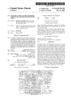
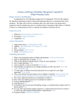
1
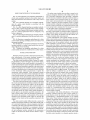
US008237389B2
(12) Ulllted States Patent
(10) Patent N0.:
Fitch et a1.
(54)
(75)
US 8,237,389 B2
(45) Date of Patent:
MULTI MODE SAFETY CONTROL MODULE
_
.
5,229,941 A
_
Inventors. Osa Edward Fitch, Nashua, NH (US),
7/1993 Hattori et 31.
5,245,422 A
9/1993 Borcherts et al.
5,400,864 A
3/1995
5,448,479 A
Eddle WllllamS, L05 0505, CA (US)
(73) Assignee: iRobot Corporation, Bedford, MA (US)
Aug. 7, 2012
Winner et al.
9/1995 Kemner et a1‘
5,469,356 A
11/1995 Hawkins et al.
5,471,560 A
11/1995 Allard et a1.
5,485,892 A
1/1996 Fujita et a1~
(Continued)
(*)
Notice:
Subject to any disclaimer, the term of this
patent is extended or adjusted under 35
U.S.C. 154(b) by 834 days.
FOREIGN PATENT DOCUMENTS
3404202 A1
5/1987
DE
(Continued)
(21) Appl. N0.: 12/269,868
_
OTHER PUBLICATIONS
(22) F1led:
Nov. 12, 2008
Murray, Sean et a1., “Continued Research in EVA, Navigation, Net
(65)
Prior Publication Data
Working and Communications Systems”, SAE Proceedings, Interna
tional Conference on Environmental Systems, Jun. 2008.
US 2010/0117585 A1
May 13, 2010
(Continued)
(51)
Int. Cl.
(52)
us. Cl. ................. .. 318/563; 318/568.12; 180/271;
(58)
Field of Classi?cation Search ................ .. 318/563,
G05B 9/02
(200601)
Primary Examiner * Walter Benson
701/45
318/568.11, 568.12, 590, 591; 701/36, 45,
701/52; 180/271; 361/1
See application ?le for Complete Search hiSIOI'Y_
(56)
(74) Attorney, Agent, or Firm * O’Brien Jones PLLC
(57)
ABSTRACT
A robotic assembly comprises: a mobile vehicle including
mechanical components con?gured to operate the mobile
vehicle in a manual mode of operation; a main poWer circuit
References Clted
for distributing a poWer signal to the electromechanical com
ponents and to external modules; an automation module con
U.S. PATENT DOCUMENTS
2,466,375 A
Assistant/Examiner * Antony M Paul
nected to the mechanical components and operable to control
4/ 1949 Carbon _
and operate the mechanical components, and a poWer circuit
2
gttenstem
4’ 1 55’4 17 A
5/1979 zitéirllsstem
and the external modules; a safety control module connected
432023037 A
5/1980 Glaser et 31‘
to the main poWer circuit, the automation module, and the
4,361,202 A
4,897,640 A
2,35%’
con?gured to distribute poWer to the mechanical components
11/ 1982 Minovitch
mechanical components; a mode selector connected to the
1/ 1990 Rapoen et a1~
main poWer circuit; and emergency stop switches con?gured
2
girt?eltet 2:151
5’076’382 A
0/1991 ‘4151;131:311 '
cal components and external modules in response to actuation
5,170,352 A
12/1992 McTamaney et a1.
Ofthe emergency StOP buttons
5,198,973 A
3/1993 Steutermann
5,204,814 A
4/1993 Noonan et a1.
to prevent a How of current to substantially all of the mechani
8 Claims, 7 Drawing Sheets
1 _________________________________________ — ‘1
:
1
i
:
r__/15
60:33:31]“ 601433236 2
(
'|
35
l
:
(N5
Mimi/1n
|
___
:
1
r\/1o
56
Safety Control MGGUIE
:
409‘
_
Autornanon
Kit
l
I
Vehicle Main
|
PowerOirouit
'
I
|
|
'
I
I
I
I
l
I
|
|
l
l
l
l
|
1
I
[_ Automation
:
I
Kt
Kit
29.,
1
I
|
1
1
|
1
I
I
' Mobile Vemcle
l
|
1
1
US 8,237,389 B2
Page 2
U.S. PATENT DOCUMENTS
5,508,689
5,511,147
5,555,503
5,586,030
5,646,843
5,652,849
5,675,229
5,698,823
5,774,069
A
A
A
A
A
A
A
A
A
5,784,023 A
5,906,645 A
5,984,880
5,987,364
6,037,901
6,038,496
6,059,063
6,072,248
6,083,020
4/1996
4/1996
9/1996
12/1996
7/1997
7/1997
10/1997
12/1997
6/1998
EP
EP
EP
EP
GB
GB
GB
GB
JP
7/1998 Bluege
5/1999 Kagawa et al.
JP
JP
JP
JP
W0
W0
W0
A
A
A
A
A
A
A
11/1999
11/1999
3/2000
3/2000
5/2000
6/2000
6,108,031 A
8/2000
6,113,395 A
6,151,239 A
6,169,940 Bl
Launder et al.
Le Gusquet et al.
Devier et al.
Dobler et al.
ShimiZu et al.
Muise et al.
7/2000 MOI
,
\(gumstmp et a1‘
,
0 601 728
0 681 230
0 835 797
1 481 945
2 128 842 A
2 332 286
2 339 869
2 400 454
3-282712
40001
5/2001
6/2001
6/2001
Rowe et 31‘
Das et al.
DilZ et al.
Arias-Estrada
6,259,980 B1
6,292,725 B1
7/2001 Peck et a1~
9/2001 Kageyama et al.
6,434,462 B 1
8/2002 Belvy et a1‘
6,438,491 B1
8/2002 Farmer
Til/£11152‘? al'
6,442,476
6,445,983
6,453,223
6’480’762
6,535,793
6,549,130
B1
B1
Bl
B1
B2
B1
6,577,909
6,600,986
6,631,882
6,633,800
B1
B2
B2
B1
6,694,260 B1
8/ 2002
9/2002
9/2002
1 H2002
3/2003
400%
6/1996
3/1997
6/1999
4/2000
2/1999
4/2001
10/2004
OTHER PUBLICATIONS
_
_
_
Yamauchi, Brian. “All-Weather Perception for Small Autonomous
UGVs”. In Proceedings of SPIE Defense and Security Conference,
Orlando, FL, Mar‘ 2008‘
Lenser, Scott et al., “Practical problems in sliding scale autonomy: A
lIlSlOW
B1
B1
B1
B1
6/1994
11/1995
4/1998
12/2004
8/1983
6/1999
2/2000
10/2004
12/1991
8-156641
9-258826
11149315 A
2000094373 A
WO 99/05580
WO 01/26338 A2
WO 2004/086084
King et al.
9/2000 Hon
11/2000 Batra
1/2001 Jitsukata et al.
2133’
6,223,110
6,233,504
6,249,215
6,253,161
FOREIGN PATENT DOCUMENTS
Rado et al.
Abdel-Malek
Kyrtsos et al.
Kemner et al.
Gudat et al.
Conway et al.
Thorne
Tanahashi
Tanaka et al.
.
.
case study”. In Proceedings of SPIE Defense and Security Confer
91199, Orlando, FL, Mar, 2008,
Cheung, Carol et al., “UAV-UGV Collaboration With a PackBot UGV
and Raven SUAV for Pursuit and Tracking of a Dynamic Target”. In
Proceedings of SPIE Defense and Security Conference, Orlando, FL,
Mar‘ 2008‘
Schoenfeld. Erik et al., “Door Breaching Robotic Manipulator”. In
Proceedings of SPIE Defense and Security Conference, Orlando. FL,
Mar 2008
Poropat et al.
Dickson et 31~
et al.
Uchlkubo et a1‘
Allard
Joao
Yamauchi, Brian. “Daredevil: Ultra Wideband Radar Sensing for
Small UGVs”, In Proceedings of SPIE: Unmanned Systems Tech
nology IX, Orlando, FL, Apr‘ 2007‘
Rudakevych, Pavlo et al, “Integration of the Fido Explosives Detector
.
onto the PackBot EOD UGV”, In Proceedings of SPIE vol. 6561,
6/2003 McGowan et al.
Man 200?
Rudakevych, Pavlo et al., “A man portable hybrid UAV/UGV sys
tem”, In Proceedings of SPIE vol. 6561, Mar. 2007.
Jones, Chris et al., “Sentinel: An Operator interface for the Control of
7/2003 steinle et a1,
10/2003 Mack
10/2003 Ward et a1~
2/2004 RekQW
Multiple Semi-Autonomous UGVs”, In Proceedings of the Associa
glscrli et 31'
6,778,097 B1
6,789,014 B1
8/2004 Kajita et al.
9/2004 Rekow et a1‘
tiAoln fggolénmanned Vehicles Systems International. Orlando, FL,
Y g‘ h. ‘B .
“A
U b R
.
U .
M
amauc i, rian.
utonomous r an econnaissance sing an
6,813,557 B2
110004 Schmidt et 31‘
Portable UGVs”, In Proceedings of SPIE: Unmanned Ground
6,845,297 B2
6,873,911 B2
1/2005 Allard
3/2005 Nishira et a1,
Vehicle Technology VIII, Orlando, FL, Apr. 2006.
Yamauchi, Brian. “Wayfarer: An Autonomous Navigation Payload
6,882,155 B2 *
4/2005 LaZZaro ...................... .. 324/418
for the PackBot”, In Proceedings of AUVSI Unmanned Vehicles
6,898,542 B2
5/2005 Ott et al.
North America 2005, Baltimore, MD, Jun. 2005.
6,901,319
6,902,021
6,945,346
6950382
5/2005
6/2005
9/2005
9/2005
Barnes, Mitch et al., “ThroWBot: Design Considerations for a Man
Portable ThroWable Robot”, In Proceedings of SPIE vol. 5804, Mar.
2005‘
Rudakevych, Pavlo et al., “PackBot EOD Firing System”, In Pro
B1
B2
B2
Bl
7,010,450 B2
Nelson _et a1~
Klkuchl et a1~
Massen et al.
Weber et 31'
3/2006 Law et al.
-
7,015,831 B2
3/2006 Karlsson et al.
ceedmgs 9f SPIE V01‘ 5804’ Mar‘ 2005'
7,079,021 B2
7/2006 snowbarger et a1‘
Yamauchi, Brian. “The Wayfarer Modular Navigation Payload for
7,278,567 B2
7,305,294 B2
7,894,951 B2 *
10/2007 Ferguson et a1‘
12/2007 Bate et a1‘
.
.
Intelligent Robot Infrastructure”, In Proceedings of SPIE vol. 5804;
Unmanned Ground Technology VII, Orlando, FL, Mar. 2005.
2/2011 Norris et a1, ,,,,,,,,,,,,,,,,,, H 701/36
Yamauchi, Brian et al., “Griffon; aman-portable hybrid UGV/UAV”,
200 1/ 0018640 A1
2002/0032511 A1
8/ 2001 Matsunaga
3/ 2002 Murakarni et al.
In Industrial Robot: An International Journal, vol. 31 No. 5, 2004.
Yamauchi, Brian. “PackBot: AVersatile Platform for Military Robot
ics”, In Proceedings of SPIE vol. 5422: Unmanned Ground Vehicle
2002/0104300 A1
55/2002 Hllnt
2003/0080772 A1
2004/0061596 A1
5/2003 Giacomini et al.
4/2004 Egan“
Technology V1, Orlando, FL, Apr‘ 2004,
Sword, Lee et al.. “Mobility Enhancements for Ballistically
2004/0114584 A1
2004/0158355 A1
6/2004 PatZ et
8/2004 Holmqvlst et a1‘
Deployed Sensors”. In Proceedings of SPIE vol. 4393, Apr. 2001.
R dakev ch Pavlo “Wave Control‘ A Method of Distributed Con
2004/0158379
8/2004
A1
2004/0168837 A1
_ _
Horbaschek
9/2004 Michaud et a1‘
“
y
’
' .
,,
'
.
:01 folrglggpeated Unit Tentacles , In Proceedings of SPIE vol. 3839,
ug.
.
1825153625211"
Rudakevych, Pavlo et al., “Micro Unattended Mobility System
2005/0092542 A1
2005/ 0159870 A1
5/2005 Turner
7/ 2005 Tohdo et al.
(MUMS)”, In Proceedings of SPIE vol. 3713, Jul. 1998.
SafeStopTM Wireless Emergency Stop System brochure, TORC
2008/0121097 A1 *
5/2008 Rudakevych et al. ..... .. 89/28.05
Technologies, LLC., copyright 2008, undated.
US 8,237,389 B2
Page 3
SafeStopTM User Manual, Revision 2.1, SafeStopTM ES-220 Wireless
Emergency Stop, TORC Technologies, LLC., copyright 2007,
undated.
De Campos, Institute of Electrical and Electronics Engineers, “Per
ception Planning as a Distributed Decision-Making Process,” Oct.
17-20, 1993, vol. 3, pp. 611-616.
Corbett, G.K., et al., “A Human Factors Tested for Ground-Vehicle
Telerobotics Research,” Southeastcon '90 Proceedings, vol. 2, pp.
618-620, 1990.
Shimoga, et al., “Touch and Force Re?ection for Telepresence Sur
gery,”IEEE, pp. 1049-1050, 1994.
Mair, “TelepresenceiThe Technology and Its Economic and Social
Implications,” IEEE, pp. 118-124, 1997.
Ohashi et al., “The Sensor Arm and the Sensor Glove IIiHaptic
Devices for VR Interface,” IEEE, p. 785, 1999.
Green, P.S., et al., “Telepresence Surgery,” IEEE, Engeneering in
Medicine and Biology, pp. 324-329, May/Jun. 1995.
Nakai, et al., “7 DOF Arm Type Haptic Interface for Teleoperation
and Virtual Reality Systems,” Proceedings of the 1998 IEEE/RS]
INTL. Conference on Intelligent Robots and System, pp. 1266-1271,
1998.
* cited by examiner
US. Patent
Aug. 7, 2012
cosmEq.
(Q.
HE
Sheet 1 of7
Pi
US 8,237,389 B2
£952
US. Patent
Aug. 7, 2012
Sheet 3 of7
US 8,237,389 B2
430
Wait for Vehicle Power Switch to Turn On a:
Main Vehicle
Power Switch On?
Power the Manual
Assembiy
442
11-4-4
Power
Stop Button ~
DOW"
Depressed?
In Automatic '
Mode?
Power the
Automation
\ Assembty
M oment-ariiy
Energize the
450 J
Hold Down
Q / R eiay
i
Power the Manual
Assembiy
452J
Power the
Emergency
Shutdown
454 J
-'
Assembiy
|___......_
FIG 3
US. Patent
Aug. 7, 2012
Sheet 4 of7
US 8,237,389 B2
472
Emergency Stop Button Depressed
In AutomaticEnd
474
Mode’?
Disrupt Current Flow to the E-Stop Redundant Relay Assembly
E-Stop Relay
AtSlop
leastRedundant
one relay inRelay
the E
Fault
Assembly Open?
496 J '
480
Remove Power From the Manual Assembly
l,
Disrupt Current Flow tothe Hold-Down Relay
Hold-Down Relay
Fault
Holcl- Down Relay ~
'
482
484
Open?
486
Disrupt Current Flow to the; Automation Assembly Relay
l
Remove Power From the Automation Assembly
488
t 490
Remove Power
From the Central
Control Assembly
Main Computer
'
Power Switch On?
499 J
Power the Central Control Assembly
FIG4
492
US. Patent
Aug. 7, 2012
Sheet 6 of7
US 8,237,389 B2
305
Instrument Panel
Auto
Man
Engine Oil "
Pressure
Reset‘
Mode Seiect
llllllillllil
Temp
0_—25U F
IIIIIHIIIIII
0 — 150 PS!
-
Water
RPM X 100
0-60
mmmlm
voitc
Gear OH ‘
_ q10 5°
Temp
0 _ 250 F
llllillllliil
(F
W
0
FIG 6B
US. Patent
Aug. 7, 2012
Sheet 7 of7
US 8,237,389 B2
380
FIG
7
US 8,237,389 B2
1
2
MULTI MODE SAFETY CONTROL MODULE
and the external modules; a safety control module installed on
the mobile vehicle and connected to the main poWer circuit,
the automation module, and the mechanical components; a
INTRODUCTION
mode selector sWitch included in the safety control module
and connected to the main poWer circuit; and emergency stop
sWitches connected to corresponding emergency stop buttons
and the mode selector sWitch, and con?gured to prevent a
How of current to substantially all of the mechanical compo
This invention relates generally to circuits and assemblies
for controlling the How of poWer through a semi-autonomous
mobile vehicle. In particular, embodiments of this invention
relate to multiple mode control modules that control the How
of poWer through the electrical and mechanical systems
nents and external modules in response to actuation of the
included in a semi-autonomous vehicle according to a chosen
mode, and a control module that further provides an emer
emergency stop buttons. An operational mode of the mobile
vehicle changes in response to actuation of the mode selector
sWitch.
gency stop assembly for removing poWer from substantially
all of the electrical and mechanical systems of the semi
The present teachings also provide a system for controlling
autonomous vehicle.
the distribution of poWer Within a mobile vehicle. The system
comprises: mechanical components of the mobile vehicle
BACKGROUND
Safety control systems are included in most process-con
trolled assemblies to provide the assemblies With the ability to
shut doWn. Multiple types of safety systems exist. Emergency
20
stop safety systems typically operate to remove poWer from
the entire assembly, While other safety systems may stop the
How of liquid or gas, or otherWise stop the process being
controlled. Emergency stop safety systems typically found in
industrial applications are connected directly to the main
system’s source of poWer. Sensors included in the safety
25
system are able to detect failure conditions Within the assem
bly and responsively activate the safety system, Which in turn
removes poWer from the assembly.
Industrial applications that employ an emergency stop
safety system rely on the system’ s ability to interact With the
application and further safely redistribute all poWer out of the
35
safety system into the larger process controlled application.
Such a con?guration can be disadvantageous because it pro
vides no alternative to removing poWer from the entirety of
the system. Additionally, safety systems that integrate the
40
emergency stop safety system can be application speci?c, not
versatile, and require costly and often complicated installa
tion.
Electro-mechanical systems similarly utiliZe emergency
stop safety sub-systems that remove all poWer from the main
45
system When an emergency event is detected. It may be inap
propriate to design an autonomous vehicle that responds to an
emergency event by removing poWer from all components
Within the autonomous vehicle. Such a design Would fail to
address the need for an autonomous vehicle to retain a level of
50
autonomy despite encountering an emergency event that
causes a poWer loss. Autonomous vehicles rely on control
systems included Within vehicle to continue collecting data
and to further provide the user and vehicle With a system
through Which the autonomous vehicle can communicate.
automation assembly, the mechanical components, the emer
gency stop buttons, and the main poWer circuit, the safety
assembly. Furthermore, these applications typically integrate
circuits and mechanical systems necessary to implement an
mobile vehicle, connected to the mechanical components and
to the main poWer circuit, and con?gured to control and
operate the mechanical components and distribute poWer
from the main poWer circuit to the mechanical components;
emergency stop buttons installed on the mobile vehicle and
connected to emergency stop sWitches responsive to actua
tion of the emergency stop buttons; and a safety control mod
ule installed on the mobile vehicle and connected to the
30
applications’ components to stop current flow through the
the components necessary to implement the emergency stop
con?gured to operate the mobile vehicle according to a user
de?ned mode of operation; a main poWer circuit of the mobile
vehicle con?gured to transmit a poWer signal to the mechani
cal components and to external modules connected to the
mobile vehicle; an automation assembly installed on the
55
control module including a mode selector sWitch for altering
the mobile vehicle’s mode of operation.
The present teachings further provide a poWer control sys
tem comprising: a safety control module enclosed at least
partially in a housing comprising mounts for mounting the
safety control module to a surface, the housing also compris
ing connectors and plugs con?gured to mate With external
assemblies and connect With circuits of the safety control
module; a mode sWitch circuit having a mode selector sWitch
designed to change an operative mode of the safety control
module in response to actuation thereof, a main poWer circuit
connected to a poWer source and con?gured to provide poWer
to a central control assembly included in an external automa
tion assembly; and an emergency stop sWitch con?gured to
activate a shutdoWn process When actuated, the shutdoWn
process removing poWer from a manual assembly, redirects a
poWer signal provided to the automation assembly, and ener
giZes the central control assembly. The mode sWitch circuit is
con?gured to distribute poWer to the safety control module
according to the operative mode.
Certain advantages of the present teachings Will be set forth
in part in the description Which folloWs, and in part Will be
obvious from the description, or may be learned by practice of
the present teachings. The advantages of the present teach
SUMMARY
ings Will be realiZed and attained by means of the elements
The present teachings provide a mobile vehicle compris
ing: mechanical components con?gured to operate the mobile
claims.
It is to be understood that both the foregoing general
description and the folloWing detailed description are exem
plary and explanatory only and are not restrictive of the
present teachings, as claimed.
and combinations particularly pointed out in the appended
60
vehicle in a manual mode of operation; a main poWer circuit
in the mobile vehicle for distributing a poWer signal to the
electromechanical components and to external modules
The accompanying draWings, Which are incorporated in
installed on the mobile vehicle; an automation module con
nected to the mechanical components and operable to control
and operate the mechanical components, and a poWer circuit
con?gured to distribute poWer to the mechanical components
65
and constitute a part of this speci?cation, illustrate one several
embodiments of the present teachings and, together With the
description, serve to explain the principles thereof.
US 8,237,389 B2
3
4
BRIEF DESCRIPTION OF THE DRAWINGS
The safety control module also provides a system for ini
tiating an emergency shutdoWn of the vehicle and the vehi
cle’s associated components While providing a minimum
level of autonomy. Included in the safety control module is a
FIG. 1 is a block diagram of an exemplary embodiment of
circuits and assemblies included in the mobile vehicle and
their interconnections and connections With a safety control
module.
FIG. 2 is a schematic diagram of an exemplary embodi
ment of a safety control module in accordance With the
main computer circuit poWered directly by the vehicle’s
poWer source and unconnected to the emergency shutdoWn
system. Connected to the main computer circuit is a central
control assembly con?gured to record system data and further
provide a control system able to communicate remotely With
present teachings.
a user and provide a minimum level of autonomous control
FIG. 3 is a How diagram depicting an exemplary embodi
ment of a How of poWer through the safety control assembly.
FIG. 4 is a How diagram illustrating an exemplary embodi
over the vehicle and its associated components.
button is depressed.
The safety control module further provides a system Where
the safety control module is contained Within a rugged hous
ing such that the safety control module can be mounted on the
FIG. 5 is a How diagram illustrating an exemplary embodi
ment of a method implemented When the reset mode is cho
surface of the vehicle and interface With the vehicle via a
system of external cables and connectors.
ment of a method implemented When an emergency stop
Certain embodiments of the present teachings provide a
sen.
safety control module used in combination With an automated
mobile vehicle for responding to emergency events by remov
FIG. 6A illustrates an exemplary embodiment of a safety
control module housing and display panel in accordance With
the present teachings.
20
FIG. 6B illustrates an exemplary embodiment of mounting
brackets included on a safety control module base in accor
dance With the present teachings.
FIG. 7 illustrates an exemplary embodiment of a safety
control module mounted to a dashboard of a mobile vehicle.
25
a manual operation mode, a user can operate the mechanical
assemblies. Automation of the mobile vehicle can be accom
DETAILED DESCRIPTION
Reference Will noW be made in detail to the present exem
plary embodiments of the present teachings, examples of
Which are illustrated in the accompanying draWings.
The safety control module provides a system for control
ling distribution of poWer throughout an automated vehicle.
Included Within the safety control module is an assembly of
circuits and mechanical systems designed to distribute poWer
to the modules and assemblies connected to the safety control
module. In particular, the assembly of circuits and mechani
cal systems distribute poWer to mechanical systems included
30
35
in the autonomous vehicle and necessary to operate the
autonomous vehicle manually. These mechanical systems
receive poWer from the safety control module When the safety
control module operates in a manual mode. When operating
in an automatic mode, the mechanical systems receive poWer
in part from an automation assembly connected to the safety
control module, and in part from the safety control module.
The safety control module provides a system for operating
the circuits and mechanical assemblies included in the safety
control module, the autonomous vehicle, and the modules
safety control module, Where the automation assembly fur
ther controls the operation of substantially all the systems
plished by an automation module that includes an automation
assembly connected to the mechanical assemblies in the
mobile vehicle. The circuits and routines included in the
automation module can be con?gured to operate and control
various mechanical and electrical systems of the mobile
vehicle such that the mobile vehicle operates autonomously
according the automation module’s circuits and routines.
In accordance With certain embodiments of the present
teachings, the safety control module can comprise a safety
control assembly including circuits and mechanical assem
blies enclosed Within a rugged housing. The housing can be
rated for military or industrial use, can be con?gured to
40
reduce heat and shield the internal safety control assembly
from electromagnetic noise, and can be ?tted With external
mounts and rails to mount the safety control assembly to a
surface. Optionally installed on the housing are a plurality of
connectors and plugs, Which can be rated for military or
45
industrial use and can mate With a variety of communication
links. Communication links can include Wires and cables, but
can alternatively include a Wireless signal or other connection
and assemblies connected to the safety control module in a
user-de?ned mode. Alteration of the mode of operation is
accomplished by actuating a mode selection sWitch. When in
an automatic mode, the safety control module distributes a
poWer signal to an automation assembly connected to the
ing poWer from all non-essential systems and assemblies
While continuing to provide poWer to essential control sys
tems Within the vehicle’s automation module. Mechanical
assemblies installed in the mobile vehicle to facilitate manual
operation of the vehicle can be connected to the safety control
module such that When the safety control module operates in
50
link able to relay signals from an external module or assembly
to modules and assemblies included in the safety control
module via a communication link connected to the safety
control module via a connector or plug installed on the safety
control module’s housing.
55
In accordance With certain embodiments of the present
teachings, installed Within the safety control module is a
mode selection circuit that includes a sWitch With positions
included in the automated mobile vehicle to automate the
corresponding to a predetermined number of, for example
operation of the vehicle and the assemblies connected to the
vehicle.
The safety control module further provides a system for
initiating an emergency shutdoWn of the vehicle and the vehi
cle’s associated components When an emergency stop button
connected to the safety control module is actuated. The emer
gency shutdoWn is facilitated by an emergency shutdoWn
system con?gured to disrupt the How of poWer to the electri
cal and mechanical systems included in the autonomous
vehicle to shut doWn the vehicle and the vehicle’s compo
three, modes. These modes can include a manual mode of
operation, an automatic mode of operation, and a reset mode
nents.
60
of operation. When the sWitch in the mode selection circuit is
actuated, the safety control module and the modules and
assemblies connected to the safety control module, can oper
ate according to the chosen mode. The manual mode of opera
tion can, for example, enable a circuit con?guration Whereby
65
the mechanical assemblies and electrical circuits included in
the mobile vehicle and able to operate the vehicle manually,
are poWered via the vehicle’s main poWer sWitch. Thus, While
the safety control module is in a manual operation mode, a
US 8,237,389 B2
5
6
user is able to operate the mechanical assemblies and electri
assembly With connectors installed directly on the circuits
and assemblies included in the safety control assembly. Still
cal circuits necessary to operate the vehicle manually. An
automatic mode of operation can be characterized by autono
mous operation of, for example, substantially all the
other embodiments may include an embodiment of the safety
control module 10 Where the circuits and assemblies included
mechanical assemblies and electrical circuits included in the
in the module are integrated directly into mobile vehicle, and
mobile vehicle. The automatic mode can enable the assem
do not include connectors or plugs. Further embodiments of
the safety control module 10 may include connectors that are
blies included in the automation module to control the opera
tion of the mobile vehicle according to stored routines and
according to user and system commands.
not rated for military or industrial use, or connectors and
plugs that are alternatively or additionally chosen based on
their ability to pass various levels of current.
In accordance With certain embodiments, the safety control
According to certain embodiments of the present teach
module can further include a series of emergency stop
(E-Stop) buttons and corresponding sWitches able to break
ings, the vehicle’ s main poWer circuit 30 can be connected to
the safety control module 10 via a poWer connector 58. This
circuit 30 can be the poWer source for the mobile vehicle 5, the
the connection betWeen the mode selection circuit and addi
tional safety control module circuitry When actuated. Dis
rupting the connection betWeen the mode selection sWitch
and the circuits and assemblies included in the safety control
safety control module 10, the automation assembly 20, the
manual assembly 15, and the emergency shutdoWn assembly
25. When the poWer sWitch included in the circuit 30 is in an
assembly further causes a disruption of current to these cir
cuits and assemblies. The net effect can be removal of poWer
from the circuits and assemblies that are dependent on their
physical connection With the mode selection circuit for
poWer. Various embodiments contemplate a connection With
the mode selection circuit characterized by a Wire, While other
embodiments may include an alternative physical connection
such as an integrated circuit, or a non-physical connection
established via an electrical pulse or created via a softWare
“off ’ position, no current is passed to the circuits and assem
blies connected to the main poWer circuit 30. The poWer
20
connector 58 can, for example, be rated to accept voltages
Within a range of 12 volts to 48 volts. The connector 58 can,
for example, be rated for military or industrial use and can
include a locking mechanism con?gured to lock the connec
tive cable’ s connector together With the poWer connector 58.
25
Alternative embodiments of the safety control module 10 can
routine con?gured to redistribute poWer throughout the safety
include a poWer connector 58 comprising one of a ring ter
control module.
In accordance With certain embodiments, removal of
poWer accomplished via actuation of an E-Stop button serves
to shut doWn substantially all systems included in the mobile
vehicle and in assemblies and modules connected to the
minal, a push-on terminal, a junction block, a spade terminal
or another type of mechanical structure able to connect an
30
external Wire or cable to the safety control module 10.
Connectors can also be provided to connect the manual
mobile vehicle, including the safety control module.
assembly 15 and the automation assembly 20 to the safety
control module 10. The manual assembly connector 56 and
Although the mobile vehicle may operate in a manual mode,
the automation assembly connectors 52 can be rated for
certain embodiments of the robotic system may retain a level
of autonomy after an E-Stop button is actuated. This level of
industrial or military use and can be connected to connection
35
autonomy can be accomplished by the main computer circuit,
Which can be directly connected to the vehicle’s main poWer
circuit, and Which can also be connected to the central control
circuit included Within the automation assembly. The ability
to communicate remotely With the vehicle and record essen
tial system data associated With the emergency shutdoWn of
the mobile vehicle can be facilitated by the central control
40
can be a poWer connection Where the circuits Within the safety
45
50
In accordance With certain embodiments of the present
teachings, the manual assembly 15 and the automation
assembly 20 can include one or more components. One or
55
rated for industrial or military use to ensure that the connec
safety control module 10 may include a rugged housing able
to accommodate a Wiring interface Whereby external modules
and assemblies Would be connected directly to the safety
control module’s internal circuits and assemblies. Still other
embodiments may include a safety control assembly inte
grated directly into a mobile vehicle or other module or sys
tem. These embodiments Would include a safety control
circuits Within the safety control assembly 10 distribute
poWer and data to the automation assembly 20 according to
the operative mode and according to data generating events
and statuses.
ule 10 and the external modules or assemblies to Which the
external cables are linked. The connectors and plugs can be
tors are both strong and durable. Other embodiments of the
control assembly 10 distribute poWer to the manual assembly
56 according to the operative mode. Further, the connection
betWeen the automation assembly 20 and the safety control
assembly 10 can be a poWer and data connection such that
trol module 10 installed on an automated mobile vehicle 5 and
additional modules and assemblies included on the mobile
vehicle 5. The safety control module 10 can be, in certain
embodiments, a stand-alone structure that includes a safety
control assembly enclosed Within a housing that is further
?tted With connectors and plugs able to mate With external
Wires, cables, and other connection links. Each connector or
plug included on the housing can be con?gured to mate With
external cables With corresponding connectors, to establish a
communicative connection betWeen the safety control mod
tor 56 can be con?gured to transmit poWer signals, the auto
mation assembly connectors 52 can be con?gured to transmit
both poWer and data signals. Thus, the connection betWeen
the manual assembly 56 and the safety control assembly 10
circuit, Which can remain poWered by the main computer
circuit despite the emergency shutdoWn.
Displayed in FIG. 1 is a block diagram illustrating an
exemplary embodiment of connections betWeen a safety con
links included in the safety control assembly to establish a
physical and electrical connection betWeen the manual and
automation assemblies and corresponding circuits in the
safety control assembly. While the manual assembly connec
60
more manual components 35 included in the manual mode
assembly 15 can correspond to the various electrical and
mechanical assemblies included in the vehicle 5 to enable a
user to operate the vehicle manually. Exemplary manual com
ponents 35 can include, for example: circuitry dedicated to a
fuel shut-off solenoid; a steering motor; and a throttle assem
bly. These components can be poWered and controlled by the
65
automation assembly 20 When the vehicle 5 operates in an
autonomous mode. HoWever, When in a manual mode, the
manual components 35 can be controlled by a user, and poW
ered via a connection With a manual relay 224 included in the
safety control module 10. The manual mode of operation can
alloW a user to operate the vehicle 5 as they Would Without
US 8,237,389 B2
7
8
robotic control and an emergency backup system. Alternative
In various embodiments, the mode sWitch circuit 202 can
be connected directly to the vehicle’s main poWer circuit 30
such that current ?oWs from the vehicle’ s main poWer circuit
embodiments of the system can include a manual mode of
operation allowing the automation assembly 20 to have semi
autonomous control over aspects of the vehicle’s operation,
30 through the mode sWitch circuit 202 and further through
While the user has control over other aspects.
the mode selector sWitch 345. When the mode selector sWitch
345 is actuated, the path of the current can be altered such that
current ?oWs through a chosen mode pin. An exemplary
situation is one Where the mode selector sWitch 345 is actu
ated so that an automatic mode is chosen. In this situation,
current can ?oW from the vehicle’s main poWer circuit 30,
through the mode selector sWitch 345, to the automatic mode
pin 206. Circuits and assemblies connected to the automatic
mode pin 206 can therefore receive current When the sWitch
Similar to the manual mode assembly 15, the automation
assembly 20 can include a number of individual automation
kits 40. The vehicle 5 can be ?tted With a single automation
assembly 40 able to control the operation of most of the
vehicle’s electrical and mechanical assemblies. The automa
tion kits 40 can provide control circuits and routines able to
automate operation of the vehicle and poWer the manual
components 35 and other assemblies and systems included on
the vehicle 5 and necessary to operating the vehicle 5 autono
345 is an automatic mode.
In certain embodiments, a Wire can connect the manual
mously. Alternative embodiments of the vehicle 5 may
include multiple kits 40, Where each kit 40 is dedicated to
controlling vehicle component subsets. Still other embodi
mode pin 204 to the manual mode relay 224. Within the
manual mode relay 224, the Wire can further connect the
ments of the vehicle 5 can include additional kits 40 dedicated
to the operation of manipulators and actuators installed on the
20
magnetic force created When the inductance coil is charged
via the Wire connecting the manual mode pin 204 to the
manual mode relay 224. When closed, the sWitch can remain
vehicle 5, such as a head, an arm, or a movable neck.
In various embodiments, the emergency shutdoWn assem
bly 25 includes a string of emergency stop (E-Stop) buttons
45 that can be, for example, connected in series and con?g
ured to send an electrical pulse to the safety control module 54
When one of the buttons is depressed. Each button 45 can be
connected to a sWitch so that When the button 45 is depressed,
closed until current is removed from the inductance coil,
25
returns to an open position.
30
mode relay 224 via a connecting Wire 270 linking the poWer
connector 58 to the closed position pin on the manual mode
relay 224. A Wire 256 can connect an open position pin on the
35
spring-loaded connector 54 can open the circuit and connect
additional E-Stop buttons 45 When additional E-Stop buttons
45 are connected to the safety control module 10 via the
connector 54. When connected, the E-Stop buttons 45 can be
placed in series With an E-Stop sWitch 220 included in the
manual mode relay 224 to the redundant E-Stop relay assem
bly 222. This con?guration can operate so that When the
manual mode relay 224 is open, the manual mode relay 224 is
part of a circuit that includes all components connected to the
automatic mode pin 206, and the manual mode assembly 15
40
safety control assembly of the safety control module 10.
Safety Control Module
In certain embodiments, the safety control module 10 can
be a stand-alone system, fully enclosed Within a rugged hous
ing 305. Individual circuits and assemblies included Within
In certain embodiments of the present teachings, the vehi
cle’s main poWer circuit 30 can be connected to the manual
control module 10 When no additional E-Stop buttons 45 are
connected to the safety control module 10. Alternatively, the
further eliminating the magnetic ?ux and corresponding mag
netic force. A counterforce generated by a spring or other type
of force-storing component in response to the elimination of
the magnetic ?ux can reposition the sWitch so that the relay
the sWitch is actuated. A connector 54 can be included on the
safety control module 10 to connect the emergency shutdoWn
assembly 25 to the safety control module 10. Inclusion of
multiple E-Stop buttons 45 is optional and the connector 54
can include an industrial grade, spring-loaded contact that
terminates and closes a circuit included Within the safety
manual mode pin 204 to an inductance coil included Within
the manual mode relay 224. The manual mode relay 224 can
be a normally open relay that closes a sWitch in response to a
45
the safety control module and con?gured to receive signal
can be poWered by the poWer control circuits and assemblies
included in the automation assembly. An alternative circuit
can be created When the manual mode relay 224 is closed such
that the vehicle main poWer circuit 30 is connected in series
With the manual mode assembly 15. This circuit layout can
alloW the manual mode assembly 15 to be poWered and con
trolled by an autonomous control system When the safety
inputs from external circuits and assemblies, can be con
control module 10 is in an automatic mode. In a manual mode,
nected to connectors and plugs 52, 54, 56, 58 that connect
external Wires and other communication links to the safety
control module 10.
An exemplary embodiment of the safety control module 10
is illustrated in FIG. 2. The mode sWitch circuit 202 installed
hoWever, the manual mode assembly 15 can be poWered
directly by the vehicle’s main poWer circuit 30, so that the
50
220, the E-Stop button assembly 25, the redundant E-Stop
relay assembly 222, the hold-doWn relay 216, and the auto
at the center of the safety control module 10 can control the
module’s operative mode by re-distributing poWer through
out the circuits included Within the safety control module 10
according to the chosen mode. Modes can be chosen via the
mode selector sWitch 345, Which can be, for example, a three
pin selector sWitch included Within the mode sWitch circuit
202, and Which can be operated by turning the sWitch’ s exter
nal dial installed on the front panel 350 of the safety control
module housing 305. Each pin Within the mode selector
55
60
sponding to the current chosen mode of operation.
vehicle main poWer circuit 30, the manual assembly 15, the
emergency shutdoWn assembly 25, the automation assembly
20, the mode sWitch circuit 202, the main computer poWer
sWitch circuit 210, the E-Stop sWitch 220, the redundant
E-Stop relay assembly 222, the hold-doWn relay 216, and the
206, and a reset pin 208. When the mode selector sWitch 345
module’s operative mode can be altered to a mode corre
mation relay 218. When the mode selector sWitch 345 is
actuated such that the safety control module 10 is in an auto
matic mode, a closed circuit can be created that includes the
sWitch 345 can represent a different mode, and can include
one or more of a manual mode pin 204, an automatic mode pin
is actuated via the sWitch’s external dial, the safety control
user is able to manually operate the vehicle.
As shoWn in the embodiment of FIG. 2, the automatic
mode pin 206 can be connected to each of the E-Stop sWitch
65
automation relay 218. The resulting closed circuit can operate
the mobile vehicle autonomously using the external control
assemblies connected to the safety control module 10 via
connectors included on the module’s housing, and using the
safety control module’s internal circuits and assemblies.
US 8,237,389 B2
10
is a string of emergency stop sWitches starting With the E-Stop
sWitch 220, Where the serial string of sWitches is connected at
The reset pin 208 can be connected to a diode 212 that is
further connected to the hold-doWn relay 216. The diode 212
can be included in the path betWeen the reset pin 208 and the
hold-doWn relay 216 to ensure that current only ?oWs from
the reset pin 208 to the hold-doWn relay 216, Which can
one end to the automatic mode pin 206 in the mode selector
sWitch 345, and at the other end to Relay 1 228 of the redun
5
dant E-Stop relay assembly 222. In the automatic mode of
prevent reverse energizing the reset pin 208 by discouraging
operation, poWer can ?oW from the vehicle main poWer cir
current ?oW from the hold-doWn relay 216 to the reset pin
208. The reset pin 208 can be a momentary sWitch, meaning
that When the sWitch is actuated, the sWitch’ s pin 208 returns
to its normal position immediately after moving into a closed
position. Thus, the reset pin 208 can be a momentary sWitch
that is part of the larger mode selector sWitch 345, and is
con?gured such that the reset pin 208 remains closed momen
tarily and immediately returns to an open position. Alterna
tive embodiments of the safety control module 10 can include
cuit 30 through the automatic mode pin 206, and through the
serial string of emergency stop sWitches to Relay 1 228.
Furthermore, in the automatic mode of operation, the induc
10
E-Stop relay assembly 222 can be energiZed such that each
relay’s sWitch is closed, creating a circuit Whereby the manual
mode relay 230 can receive poWer from the vehicle main
poWer circuit 30 to poWer the manual mode assembly 15 via
the circuit created by the closed emergency stop relays 228,
226.
Actuation of the E-Stop sWitch 220 or any one of the
emergency stop buttons 45 While in the automatic mode of
a reset pin 208 able to remain in a closed position for an
inde?nite period of time or until the sWitch is actuated to
move the reset pin 208 back into the open position.
In certain embodiments, the hold-doWn relay 216 can be a
latching relay With tWo states, Which is con?gured to remain
tance coils of Relay 1 228 and Relay 2 226 of the redundant
20
operation, can break the physical and electrical connection
betWeen the automatic mode pin 206 and the redundant
in an existing state When current is removed from the induc
E-Stop relay assembly 222. The resulting open circuit can
tance coil. Elimination of the magnetic force produced by the
charged inductance coil causes the relay’s pins to remain in
therefore be unable to energiZe the inductance coils included
the position they Were in immediately before current Was
removed. An example of this Would be a normally open
hold-doWn relay 216 that closes When current is applied to the
hold-doWn relay 216 and remains closed When current is
removed from the hold-doWn relay 21 6. The hold-doWn relay
216 can be connected to the reverse-energizing prevention
diode 212 via, for example, a Wire connecting the diode 212
to the C4 pin on the hold-doWn relay 216. The C5 pin on the
hold-down relay 216 can be tied to the output of the C4 pin
via, for example, a Wire, While the C6 pin can be tied to the
output of the C2 pin via, for example, a Wire. The redundant
E-Stop relay assembly 222 can be connected to the hold
doWn relay 216 via, for example, a Wire connected from the
output of the inductance coil in Relay 2 226 in the redundant
to open and further breaking both the physical and electrical
connection created by the Wire 262 connecting the main
poWer circuit 30 to the E-Stop relay assembly 222, and the
Wire 256 connecting the Al pin of relay 1 228 to the manual
E-Stop relay assembly 222. The automation relay 218 can be
connected to the hold-doWn relay 216 via, for example, a Wire
connecting the C3 pin of the hold-doWn relay 216 to the D1
in Relay 1 228 and Relay 2 226, causing the relays 228, 226
25
relay 224. This break can stop the How of current to the
manual relay 224 and to the manual assembly 15. Thus, by
30
ration can provide a circuit Where actuation of an emergency
stop button or sWitch causes poWer to be removed from all
electrical and mechanical systems included in the vehicle.
35
Furthermore, the con?guration can alloW the user to install
multiple emergency stop buttons on the vehicle, and to have a
level of control over the placement of those emergency stop
buttons.
40
included in the vehicle 5 can be designed to include mechani
In certain embodiments, the mechanical assemblies
pin included in the automation relay 218.
In various embodiments, the hold-doWn relay 216 can
route poWer through the safety control module 10 according
to the chosen mode of operation and according to Whether or
not the emergency stop system has been activated. The hold
doWn relay 216 can be a normally open relay that closes When
a current is passed through the inductance coil. The induc
tance coil in the hold-doWn relay 21 6 can receive current from
45
an output Wire 264 originating in the E-Stop relay assembly
222. Actuating the E-Stop sWitch 220 or an adjunct E-Stop
actuating an E-Stop sWitch, poWer can be removed from the
manual components included in the vehicle 5. This con?gu
50
cal safety systems that “fail safe” When poWer is removed
from the mechanical assemblies. An example Would include
a mechanical clutch that implements a safety brake When
poWer is removed from the vehicle 5. In this example, When
an E-Stop button is depressed, poWer is removed from the
manual assembly 15 and further from the mechanical com
ponents and assemblies 35 included in the manual assembly
15. When this occurs, the mechanical clutch Would activate
the mechanical safety brake, Which Would retard movement
of the vehicle 5 and eventually cause the vehicle 5 to stop
button included in the emergency shutdoWn assembly 25 can
moving. Alternative embodiments can include a safety con
cause the relays included in the E-Stop relay assembly to
trol module 10 that includes mechanical assemblies for
retarding motion of the vehicle 5 When the emergency shut
doWn system is activated.
close and can generate a current that energiZes the inductance
coil in the hold-doWn relay 216. The hold-doWn relay 216 can
respond to activation of the emergency shutdoWn system by
removing poWer from the automation assembly 20.
Referring to the embodiment of FIG. 2, the emergency
55
and on a navigation console included in the mobile vehicle 5.
The emergency stop button is included in the emergency
shutdoWn system can include the emergency shutdoWn
assembly 25, E-Stop buttons 45 included in the emergency
shutdoWn assembly 25, the E-Stop sWitch 220, and the redun
dant emergency stop (E-Stop) relay assembly 222. The
60
shutdoWn assembly 25, Which is in series With the E-Stop
sWitch 220. While in the automatic mode of operation, a user
depresses the emergency stop button Which causes the
attached sWitch to open thereby creating a break in the con
nection betWeen the E-Stop sWitch 220 and relay 1 228. The
E-Stop sWitch 220 can be connected on one end to the auto
matic mode pin 206 in the mode sWitch circuit 202, and at the
other end to the emergency shutdoWn assembly 25. Each
E-Stop button 45 included in the emergency shutdoWn assem
bly 25 can be, for example, a sWitch that is connected in serial
to both prior and subsequent E-Stop buttons 45. What results
The folloWing example illustrates an exemplary embodi
ment of an operation of the emergency stop assembly. An
emergency stop button is installed next to a steering Wheel
65
break can cause the inductance coil in Relay 1 228 to de
energiZe, Which can cause the inductance coil in Relay 2 226
to de-energiZe. In response to the elimination of the magnetic
US 8,237,389 B2
11
12
?eld in Relay 1 228 and Relay 2 226, each relay’s switch
system and further record and store system data. Alternative
moves from the energized position of A2, B2 to the de
embodiments of the system can include a central control
energiZed position of A3, B3. The movement of Relay 1’s
sWitch to the A3 pin position and Relay 2’s sWitch to the B3
assembly 252 that can mobiliZe mechanical assemblies, reset
the safety control module 10, or provide some other autono
mous ability.
Further connected to the automation assembly 20 via con
nectors 52 installed on the housing 305 is, for example, an
LED 244 connected via a Wire 250 installed betWeen the
automation assembly 20 and the LED 244. The LED 244 can
be installed on the safety control module 10 and can be
con?gured to illuminate When the computer poWer sWitch
included in the computer poWer circuit 210 is in an on posi
tion. Also connected to the automation assembly 20, for
example via a Wire 246, is a display panel circuit 242 able to
accept data sent to the display panel circuit 242 from the
automation assembly 20 regarding the state of various sys
pin position creates an open circuit Where current no longer
?oWs from the vehicle main poWer circuit 30 to the manual
mode relay 230 via Wires 262 and 256. The resultant open
circuit removes poWer from the Wire 258 connecting the
manual mode assembly 15 to the safety control module 10,
Which further removes poWer from the components included
in the manual mode assembly 15.
Removing current from the inductance coils included in
the relays included in the redundant E-Stop relay assembly
222, per the above exemplary operation embodiment, further
causes current to be removed from the C2 pin in the hold
doWn relay 216. In the automatic mode of operation, the
hold-doWn relay 216 is energiZed such that the relay 216 is
closed. The hold-doWn relay 216 can be a normally open relay
that returns to the open position When current is removed
from the inductance coil included in the hold-doWn relay 216.
The open position is characterized by a position in Which the
sWitches contact the C3 and C6 pin. When the hold-doWn
relay 216 moves to the open position, poWer is removed from
the C2 pin and the C5 pin. Tied to the C5 pin via a Wire is the
C4 pin, Which is further connected to the inductance coil
tems installed in the vehicle 5. This status data can be dis
played to the user via displays 315 installed on the safety
20
sensor, and the vehicle gear oil temperature sensor.
Operation of the Safety Control Module
FIG. 3 is a How diagram depicting an exemplary embodi
25
included in the hold-doWn relay 216 and the Wire 232 con
necting the D1 pin of the automation relay 218 to the hold
doWn relay 216. Removal of poWer to the C4 pin de-energiZes
the inductance coil included Within the hold-doWn relay 216,
and removes current from the automation relay 218. Removal
of current from the automation relay 218 causes the sWitch in
the automation relay 218 to open or more speci?cally to move
30
to the D3 position. When in the D3 position, digital signals
35
LED 214 to poWer doWn.
In certain embodiments, the automation assembly 20 can
include a central control assembly 252 comprising control
circuits necessary to retain a minimum level of autonomy
When the emergency shutdoWn system is activated. In such an
40
dependent on the poWer source made available When the main
vehicle poWer sWitch included in the vehicle main poWer
circuit 30 is on, and the module Waits until the poWer sWitch
is in an on position 430 to resume operation. When a voltage
circuit 202 and the circuits and assemblies connected to the
mode sWitch circuit 202, can be responsive to a mode change
accomplished via actuation of the mode selector sWitch 345.
The manual relay 224 can check Whether the sWitch is in the
manual mode of operation 434, and can direct poWer to the
manual assembly 442 When the sWitch is in a manual mode
a Wire 248 connected through a connector on the automation
assembly 20 to the central control assembly 252, and further
45
position.
In various embodiments of the present teachings, the cir
cuits and assemblies connected to the automatic mode pin
main computer poWer circuit 210 can include a main com
puter poWer sWitch connected to the vehicle main poWer
circuit 30 via an internal Wire 254 such that When the vehicle
is poWered, the computer poWer circuit 210 can distribute
poWer to assemblies connected to the computerpoWer sWitch.
included in the safety control module 10, and based in part on
the presence of a voltage source. The safety control module
10 can be responsive to positional changes of the mode selec
tor sWitch 345 When the main vehicle poWer sWitch is on 432.
is present in the safety control module 10, the mode sWitch
embodiment, connected to the central control assembly 252 is
connected to the on position of the main computer poWer
sWitch in the main computer poWer circuit 210 via a connec
tor 52 installed on the safety control module’s housing. The
ment of a How of current through a safety control module 10
When the module operates in one of the operational modes.
FloW of current through the safety control module 10 can be
based in part on the state of the circuits and assemblies
Operation of the safety control module 10 can be partly
can no longer pass from the automation assembly 20 to the
automation relay 218, thereby causing the automatic mode
control module display face 350. Exemplary systems moni
tored by the display panel circuit 242 can include the vehicle
engine oil pressure sensor, the vehicle Water temperature
206 can be responsive to a change in mode to the automatic
50
In particular, When the vehicle 5 is poWered and the sWitch
mode of operation. When the mode selector sWitch changes
position to the automatic mode position, the circuits and
assemblies connected to the automatic mode pin 206 through
the serial string created by the E-Stop sWitch 220 and the
included in the main computer poWer circuit 210 is in an on
emergency shutdoWn assembly 25 can be responsive to the
position, the central control assembly 252 can be poWered.
position change When all E-Stop buttons and their corre
The main computer poWer circuit 210 may not be connected
55
to the emergency shutdoWn system, and so When the emer
gency shutdoWn system is activated, the main computer
poWer circuit 210 remains unaffected. This con?guration can
ensure that a control circuit Will remain poWered despite an
emergency shutdoWn and provided that the vehicle’s main
poWer sWitch remains in an on position. Ensuring operation
of the central control assembly 252 can provide the vehicle 5
and the user With a minimum level of autonomy. This
diverted from the E-Stop relay assembly 222, causing all
60
autonomy can alloW the user to communicate With the vehicle
5 despite an emergency shutdoWn, and can provide data
indicative of the status of the vehicle’s systems by alloWing
the central control assembly 252 to operate a communication
sponding sWitches remain lifted and are not depressed or
actuated. When any one of the E-Stop buttons in the E-Stop
button chain created by the E-Stop sWitch 220 and the emer
gency shutdoWn assembly 25 is depressed, poWer can be
65
circuits and assemblies Within the safety control module 10
and connected to the safety control module 10 to poWer doWn.
Also shoWn in FIG. 3, after checking Whether or not an
E-Stop button is depressed 446, a path can be created from the
automatic mode pin 206 to the redundant E-Stop relay assem
bly 222 through Which current may pass. This path can remain
present While all E-Stop buttons remain lifted, the poWer
signal originating from the vehicle main poWer circuit 30 can
US 8,237,389 B2
13
14
be transmitted through the E-Stop relay assembly 222 to both
the hold-doWn relay 216 and the manual relay 224. The hold
doWn relay 216 transmits the signal to the automation relay
control assembly 252 in the automation assembly 20 can be
energiZed 492 With poWer redistributed by the main computer
poWer sWitch circuit 210. When the main computer poWer
218, Which can transmit the signal to the automation assem
sWitch is open and no current is ?oWing into the main com
puter poWer sWitch circuit 210, poWer can be removed 499
bly 20 causing the assembly 20 to be powered 450. The
manual relay 224 can transmit the poWer signal to the manual
assembly 15 to poWer the manual assembly 452. In certain
embodiments, installed betWeen the mode sWitch circuit 202
from the central control assembly 252.
Alternative embodiments of the safety control module 10
and the E-Stop relay assembly 222 are the E-Stop sWitch 220
and the emergency shutdoWn assembly 25, Which are poW
tine that substantially emulates the logical process repre
sented by the How diagram in FIG. 4. This embodiment of the
ered by the transmitted poWer signal 454.
module 10 can include a central control circuit able to execute
can include a central processor con?gured to execute a rou
When not in manual mode 434 and not in automatic mode
a stored softWare routine able to respond to depression of an
436, the hold-doWn relay 216 can be responsive to a change in
the mode selector sWitch’s position to a reset mode position.
Ifa reset mode position is sensed 438, a poWer signal can be
emergency stop button by carrying out steps substantially
similar to those carried out by the circuits and assemblies
included in the safety control module 10.
FIG. 5 illustrates an exemplary method by Which the reset
transmitted to the hold-doWn relay 216 causing the relay’s
sWitches to change position. The reset mode pin 208 can be a
momentary sWitch that returns to the automatic mode posi
tion immediately after the poWer signal is transmitted to the
hold-doWn relay 216. Should the sWitch not be in a reset
mode can reset the state of the hold-doWn relay 216. When the
mode selector sWitch 345 is moved to the automatic position
20
position, the circuits in the safety control module 10 can
very short period of time before returning the mode selector
sWitch 345 to the automatic mode position. While the mode
continue to Wait for the vehicle poWer sWitch to turn on 430
and periodically check Whether this sWitch is on 432. At any
point in time, poWer How to any one of these components can
be interrupted by a change in position of the mode selector
402, the sWitch 345 is in a position from Which it can momen
tarily move to the reset position 414. The reset pin 208 is a
momentary sWitch that can remain in the reset position for a
25
selector sWitch 345 is in the reset position, current can pass
from the vehicle main poWer circuit 30 voltage source
sWitch 345. Response to a change in mode can be substan
through the mode sWitch circuit 202 through the reset mode
tially instantaneous.
pin 412 as an instantaneous pulse of current. A connection
Wire installed betWeen the reset mode pin 208 and the reverse
While FIG. 3 illustrates an exemplary method of distribut
ing poWer through the safety control module 10 using circuits
and assemblies, an alternative embodiment of the safety con
30
trol module 10 can use a microprocessor or other control
circuit to accomplish the logical decision-making processes
netic ?eld can be created When a current passes through the
inductance coil. This magnetic ?eld can cause the pins in the
accomplished by the safety control module 10. In such and
embodiment, a microprocessor, microcontroller, single board
computer, logical gate array, or other control unit can input
35
poWer from the vehicle’ s main poWer circuit 3 0 and distribute
the poWer according to the mode of operation, the state of the
emergency stop button, and the state of the main poWer sWitch
circuit 210.
FIG. 4 is a How diagram of events that can occur folloWing
actuation of an emergency stop button at step 472. When any
one of the emergency stop buttons are depressed and the
energiZing prevention diode 212 can transmit instantaneous
pulse through the diode 410 to the hold-doWn relay 216 to
energiZe the hold-doWn relay’s inductance coil 408. A mag
40
hold-doWn relay’s sWitch to change positions from an open
position to a closed position 406. The hold-doWn relay 216
can be a latching relay, meaning that the relay retains is most
recent position When current is removed from the relay’s
inductance coil. The instantaneous pulse can exist for a mini
mum time duration needed to cause the relay 21 6 to close, and
a minimum time period needed to ensure that the relay 216
remains in a closed position 404.
verify that the module 10 is operating in an automatic mode
474. If the module 10 is not in the automatic mode, then no
action is taken 494. Otherwise, When in automatic mode, the
How of current to the E-Stop relay assembly 220 can be
disrupted 476, causing the sWitches included in the assem
45
Alternative embodiments of the safety control module 10
can implement the exemplary reset method illustrated in FIG.
5 using a central control circuit con?gured to execute a soft
Ware routine able to substantially reproduce the method steps
outlined in FIG. 5. Such embodiments of the safety control
module 10 can include a microprocessor, microcontroller,
single board computer, logical gate array, or other control unit
bly’s relays to change position. When the module 10 detects
that neither of the relays included in the E-Stop relay assem
bly changed position 478, an E-Stop relay fault can be gen
50
hold-doWn relay 216.
button’s corresponding sWitch is activated, the connected
circuits can check the state of the mode selector sWitch 345 to
able to execute a stored softWare routine able to reset the
Safety Control Module Housing and Mounting
A rugged housing 305 can encase the internal components
of the safety control module 10 so that the safety control
erated 496. If at least one of the relays included in the E-Stop
relay assembly changes position to an open position, an open
circuit can be created, removing poWer from the manual mode
assembly 480 and disrupting current How 482 to the hold
doWn relay 216. Disruption of current How 482 to the hold
module 10 can be installed as a stand-alone component. An
55
doWn relay 216 can cause the sWitches included in the hold
doWn relay to change position. If the sWitches fail to change
position 484, a hold-doWn relay fault can be generated 498.
60
When the hold-doWn relay 216 sWitch properly changes posi
be sealed according to industrial and military speci?cations,
to prevent liquids and particles from entering the housing
internal chamber. Proper ventilation can be included via a
mechanical vent assembly to facilitate the movement of air
tion to an open position, current How to the automation
assembly relay can be disrupted 486, causing poWer to be
removed from the automation assembly 488. A check can be
performed to determine Whether the main computer poWer
sWitch in the main computer poWer sWitch circuit is closed
and in an on position 490. If the sWitch is closed, the central
exemplary embodiment of a housing 305 is illustrated in FIG.
6A, and comprises industrial- or military-rated material pro
viding a signi?cant amount of protection to the internal com
ponents of the safety control module 10. The housing 305 can
through the housing internal chamber, and to prevent over
heating the safety control module’s internal circuits and
65
assemblies.
In certain embodiments, installed proximate to edges of the
rugged housing 305, are mounts 325 for mounting the safety
US 8,237,389 B2
15
16
control module 10 to a surface. The mounts 325 can comprise
?cations for commercial rails such as, for example, Picatinny
a rounded plate fused to the rugged housing 305, having an
rails. The rails 340 can alternatively or additionally include
indentation through Which a fastener can be placed. An exem
plary use of the mounts 325 is shoWn in FIG. 7, Where the
safety control module 10 is mounted to a dashboard 382 of a
custom siZed and con?gured rails able to mate With a corre
sponding rail assembly. Other embodiments of the safety
control module 10 can comprise a housing 305 that does not
have an additional mounting or rail system installed along the
mobile vehicle. In this exemplary embodiment, the mounts
325 can be placed ?ush With the dashboard 382, and a fastener
can be placed into each mount’s indentation and drilled into a
surface of the dashboard 382 to anchor the mount 325 to the
dashboard surface. The mounts 325 can provide stability and
housing’s bottom panel.
support to the safety control module 10 by fastening the
prising a display panel, gauges, a throttle, a steering Wheel,
housing 305 to an additional surface. Fastening can be
accomplished With one or more of screWs, nails, clips, or any
and other components typically included on a mobile vehi
other mechanical component able to anchor the rugged hous
mounted to the console’s dashboard 382 via the mounts 325
An exemplary dashboard 382 and safety control module 10
assembly are display in FIG. 5. This illustration depicts a
control console 380 installed in a mobile vehicle and com
cle’s control console 380. The safety control module 10 is
ing 305 to a surface via the mounts 325.
included on the housing 305. An additional E-Stop button 45
Referring to FIG. 6A, the safety control module 10 can
comprise an instrument display panel 350 installed Within the
housing 305, external to the module’s internal circuits and
assemblies. The instrument display panel 350 can include a
mode selector dial and sWitch 345 included in the mode
is installed on the dashboard 382 and is connected to the
safety control module 10 via an external connector 310. The
20
sWitch circuit 202. Each mode can be represented as a posi
tion on the mode selector dial, and choosing a mode of opera
tion can require the user to turn the dial 345 to the preferred
mode.
In various embodiments of the present teachings, the
instrument display panel 350 can comprise displays 315 con
?gured to display the status of assemblies included in the
vehicle 5. The displays can be installed Within the housing
305 and the instrument display panel 350, and can be con
nected internally to the display panel circuit 242. Each dis
25
30
ings being indicated by the folloWing claims.
play 315 can correspond to a separate and distinct electro
mechanical assembly included in the vehicle 5, and can
change state according to output from the display panel cir
cuit 242. Exemplary displays include those that display the
vehicle’s engine oil pressure, Water temperature, gear oil
temperature, and engine rpms.
In certain embodiments, included on the instrument panel
What is claimed is:
35
and plugs 330 can be con?gured to mate With external con
nectors and plugs and provide a physical and electrical con
nection betWeen an external assembly and the safety control
module 10. The connectors and plugs can be installed accord
ing to industrial or military speci?cations, and can be indus
trial or military rated connectors and plugs. The emergency
stop button 320 connected to the E-Stop sWitch 220 included
in the safety control module 10 can be mounted to the top of
1. A mobile vehicle, comprising:
mechanical components con?gured to operate the mobile
vehicle in a manual mode of operation;
a main poWer circuit in the mobile vehicle for distributing
a poWer signal to the electro-mechanical components
and to external modules installed on the mobile vehicle;
display 350 are connectors 310 able to mate With external
connectors and provide a physical and electrical connection
betWeen an external assembly and the safety control module
10. Additional connectors 335 and plugs 330 can be installed
on the surface of the housing 305. Each of the connectors 335
E-Stop button 45 is included in the E-Stop button assembly 25
and is connected in series With the E-Stop button 320
mounted to the top of the safety control module 10. The
E-Stop button 45 is also connected internally to the E-Stop
sWitch 220. When the E-Stop button 45 is depressed, the
emergency stop system can be activated creating an open
circuit and further removing poWer from substantially all of
the vehicle’s electro-mechanical assemblies.
Other embodiments of the present teachings Will be appar
ent to those skilled in the art from consideration of the speci
?cation and practice of the embodiments disclosed herein. It
is intended that the speci?cation and examples be considered
as exemplary only, With a true scope and spirit of the teach
40
an automation module connected to the mechanical com
ponents and operable to control and operate the
mechanical components, and a poWer circuit con?gured
to distribute poWer to the mechanical components and
the external modules;
45
a safety control module installed on the mobile vehicle and
connected to the main poWer circuit, the automation
module, and the mechanical components;
50
the housing 305. When the E-Stop button 320 is depressed,
the E-Stop sWitch 220 canbe actuated and the emergency stop
a mode selector sWitch included in the safety control mod
ule and connected to the main poWer circuit; and
emergency stop sWitches connected to corresponding
emergency stop buttons and the mode selector sWitch,
and con?gured to prevent a How of current to substan
system can be further activated to remove poWer from sub
tially all of the mechanical components and external
stantially all of the assemblies included Within the vehicle 5.
modules in response to actuation of the emergency stop
While the illustrated exemplary rugged housing 305 is
55
substantially rectangular in shape, alternative housing shapes
may be used, including round, triangular, square, or any other
shape able to enclose and provide structure to the internal
components of the safety control module 10. Other embodi
ments of the safety control module 10 may not include a
sWitch, and
60
housing 305, but rather may include internal safety control
module components integrated directly With the internal elec
tromechanical components of the mobile vehicle.
FIG. 4B illustrates a bottom panel of the housing 305. To
further provide support and to ensure versatility, the bottom
panel can be ?tted With mounting brackets comprising rails
340. The rails 340 can be con?gured according to the speci
buttons,
Wherein an operational mode of the mobile vehicle
changes in response to actuation of the mode selector
Wherein the automation module comprises a central con
trol assembly connected to a main computer circuit and
con?gured to receive a poWer signal from the main com
puter circuit, and the main computer circuit is con?gured
to receive the poWer signal from the main poWer circuit
and distribute the poWer signal to the central control
65
assembly.
2. The mobile vehicle of claim 1, Wherein the mechanical
components are connected to electrical circuits.
US 8,237,389 B2
17
18
5. The system of claim 4, Wherein the mechanical compo
3. The mobile vehicle of claim 1, wherein the main com
puter circuit continues to distribute current to the central
control assembly in response to actuation of an emergency
nents are connected to control circuits.
6. The system of claim 4, Wherein the emergency stop
sWitches are con?gured to disrupt a How of current to the
stop button.
4. A system for controlling the distribution of poWer Within
a mobile vehicle, the system comprising:
mechanical components of the mobile vehicle con?gured
mechanical components and the automation assembly in
response to actuation of the emergency stop buttons.
7. The system of claim 6, Wherein the central control
assembly retains poWer in response to actuation of the emer
gency stop buttons.
to operate the mobile vehicle according to a user-de?ned
mode of operation;
a main poWer circuit of the mobile vehicle con?gured to
transmit a poWer signal to the mechanical components
and to external modules connected to the mobile vehicle;
an automation assembly comprising a central control
assembly, installed on the mobile vehicle, connected to
the mechanical components and to the main poWer cir
8. A poWer control system comprising:
a safety control module enclosed at least partially in a
housing comprising mounts for mounting the safety
15
trol module;
a mode sWitch circuit having a mode selector sWitch
cuit, and con?gured to control and operate the mechani
cal components and distribute poWer from the main
poWer circuit to the mechanical components;
a main computer circuit con?gured to receive the poWer
signal from the main poWer circuit and distribute the
designed to change an operative mode of the safety
control module in response to actuation thereof;
20
con?gured to provide poWer to a central control assem
poWer signal to the central control assembly;
an emergency stop sWitch con?gured to activate a shut
25
doWn process When actuated, the shutdoWn process
removing poWer from a manual assembly, redirects a
poWer signal provided to the automation assembly, and
energiZes the central control assembly,
a safety control module installed on the mobile vehicle and
connected to the automation assembly, the mechanical
components, the emergency stop buttons, and the main
poWer circuit, the safety control module including a
mode selector sWitch for altering the mobile vehicle’s
mode of operation.
a main poWer circuit connected to a poWer source and
bly included in an external automation assembly; and
emergency stop buttons installed on the mobile vehicle and
connected to emergency stop sWitches responsive to
actuation of the emergency stop buttons; and
control module to a surface, the housing also comprising
connectors and plugs con?gured to mate With external
assemblies and connect With circuits of the safety con
Wherein the mode sWitch circuit is con?gured to distribute
poWer to the safety control module according to the
30
operative mode.