1
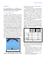
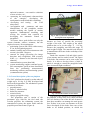
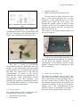
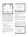
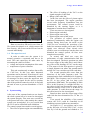
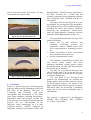
28TH INTERNATIONAL CONGRESS OF THE AERONAUTICAL SCIENCES
UNMANNED MEASUREMENT PLATFORM FOR
PARAGLIDERS
Andras Nagy*, Jozsef Rohacs*
*Budapest University of Technology and Economics
Department of Aircraft and Ships
[email protected]; [email protected]
Keywords: UAV, paraglider, measurement, distributed control system, avionics
Abstract
The design of remotely controlled and unmanned aerial
system (UAS) is an important direction in modern aircraft
development. Some researches are aimed at UAS’s which
use paraglider canopy as their wing. This group of UAS’s
can be successfully used in applications where stable, low
speed flying and mobility are required.
This paper introduces a UAS test platform
developing for testing the different paragliders. The test
platform is planned to use for different purposes: (i)
investigation and calibration of the sensors developing
for the special small (leisure or sport) flying machines,
(ii) measuring the aerodynamic characteristics of the
canopies, (iii) developing and testing
the UAS
subsystems, (iv) investigation and parameter and state
identification of the paraglider motion equations,
mathematical model that required for developing the
automatic control of paragliders.
The developing unmanned measurement platform is
equipped by (i) sensors and air data collection unit
including GPS positioning, pressure and temperature
sensors, MEMS based local force components/stress
measuring sensors, etc., (ii) control sub-systems
containing power and control forces' actuators and
control unit as well as (iii) the info-communication
system. The most challenging part of the test platform is
the electronic system. We had provided a robust, fail safe
remote control system for the test platform. The basic
intelligent distributed control system consists of the
ground station, the radio link and propulsion and control
forces' actuators.
1 Introduction
Nowadays, the unmanned aerial systems (UAS)
are developing very widely for many different
application purposes as surveillance, fire, or lost
persons surveillances, area monitoring, weather
investigation, hurricane monitoring, land
observation,
pipeline
inspection,
traffic
monitoring, damage assessment, and so on [1 3]. Most of them are fixed and rotary wing
aircraft that may have relatively high speed,
large dimensions and weigh in comparison with
the "commercial load", sensors, data collections,
evaluation and communication equipments.
Generally, the lighter than air UAS, airships and
balloons have much more larger airframe then
their payload.
Building UAV with paraglider canopy is
not too old conception, still seems only one
company in the USA developing his main
activity in this field [4]. Other company is
developing a special, man-portable hybrid
UGV/UAV [5]. Such system has a very
important advantage comparing to UGV or
UAV, because the target areas can be
investigated and monitored by the ground
vehicle, why the vehicle can return to its home
basis by air.
According to the US roadmap [2], after
2020 the UAS will be operated by autonomous
control system, only.
For developing the
autonomous control system for PPG, its motion
dynamics must be studied. Therefore a special
PhD research had been initiated by the
Department of Aircraft and Ships at the
Budapest University of Technology and
Economics (BME). The first part of research
had a goal setting up and designing, realizing a
special measuring system for estimating the
PPG flight dynamics.
This paper gives information about the
civilian application of PPG UAV, shortly
introduces the motion equations, defines the
requirements in measuring systems and
developing the measuring system that in
realization at the Department of Aircraft and
Ships, BME.
1
A. Nagy, Prof. J. Rohacs
2. PPG UAS
For understanding the requirements to
measuring platforms the operational concepts,
application of the PPG and its modeling and
control developments must be analyzed.
2.1. PPG UAS application
A special UAS, paraglider has several
advantages comparing to the other UAS when
the stable, low speed flying and mobility are
required [4]. May be, the most important benefit
of the powered paragliders for unmanned
aircraft use is their unique ability to glide to the
ground in a relatively safe manner, even if all
control systems are disabled. This is particularly
desirable in urban environments where a failure
of any large UAV would likely result in
collateral damage to structures on the ground.
Therefore the paragliders are widely used for
leisure flying, they say it is the freest way of fly.
An another important advantage of the PPG
UAV is their excellent portability [5], since it is
folded on the ground, and unfolded when it
flies. Because the paraglider is subject to wind
disturbances, the portability justifies the uses of
the paragliders as UAV, for example as a
recovery system of a spacecraft [6]. However, in
order to use the UAV not as a glider but as an
aircraft, it needs thrust generated by a propeller,
lift determined by a parafoil or canopy and a
suspended payload body (traveler) (Fig.1).
developed on it, so it has coupled mechanical –
aerodynamical behaviour.
Actually several types of an autonomous
PPG have already been produced and sold on a
commercial basis. For instance, the PPG, which
is guided by GPS and flied for a long time
(about 1.5 days maximum), was developed
about ten years ago. In addition to the
portability of a PPG, its low flight speed is
suitable for land observation of a small area.
Furthermore, a PPG is safe and survivable in
case of engine failure, since it can continue a
stable gliding flight without thrust and can be
guided to a safe landing point.
The comparison of a powered paraglider
(PPG) UAV with fixed (rigid) wing aircraft
(Fig.2.) shows that the PPG UAV requires 2 - 4
times more fuel, while its crusing speed much
more less. However, in case of area monitoring,
when the cruising time is important, then the
using the powered paragliders is a better
solution.
Fig. 2. Comparison of rigid wing aircraft and PPG
UAV
Fig. 1. Powered paraglider
The paragliders have strongly flexible
wing, the shape (and the profile) of the wing
depends on aerodynamic forces which
The missions outlined below are
particularly well suited to powered paragliders,
as opposed to conventional fixed-wing aircraft
and rotorcraft, due to the PPC’s unique flight
characteristics [7]:
• Aerial Spraying (spraying of various
fertilizers and pesticides thanks to large
payload capabilities, coupled with the slow,
constant-speed flight of PPG allow for a
low-turbulence spraying platform with a
long endurance time).
• High-Resolution Photography (due to slowmoving, low altitude platform).
2
A. Nagy, Prof. J. Rohacs
•
•
•
•
Tactical Unmanned Aerial Vehicles (PPG
may use fort such missions because its lightweight, collapsible wing, powering,
allowing the deployment of man-portable
units within minutes).
Ground Penetrating Radar (this emerging
technology developing for observing the
underground anomalies needs slow flight
ability, large wing area, keeping a fixed
altitude).
Radio Frequency Relay (ideally might be
supported by PPG having low speed long
endurance flight, high payloads, retaining its
virtually static position in low altitude flight
with sustained winds less than 10-20 mph).
Aerial monitoring of air quality (due to low
speed and altitude).
2.2. PPG aerodynamic and flight control
models
Paragliders are unique flying vehicles,
containing the flexible canopy and rigid (in case
of human operator nearly rigid) body payload.
The canopy is used for generation the
aerodynamic lift required for flights. However
aerodynamic forces and moments burning on
the canopy depend on the actual loads (form of
canopy). Generally, the estimated values from
free flight test measurements [8, 9] show that,
the observed maximum lift to drag ratios near
2.5, high profile drag and low maximum lift
coefficients when compared to a standard rigid
wing.
From the flight dynamics point of view, one
of the most interesting features of the
paragliders is their inconveniences to
longitudinal control. They have only lateral
control that can be realized by changing the
length of the appropriate (left or right)
suspension lines. By this way the canopy form
is shaping (deforming) and the drag as usually
rising significally and lift increasing only
slightly. So, this “breaking” and the moments
developed cause the tilt of canopy. Canopy
changes
created
by
brake
deflection
subsequently cause predictable changes in
aerodynamic loads which is leveraged for
control of the vehicle [10]. For most parafoils,
deployment of the right brake causes a
significant drag rise and a small lift increase on
the right side of the parafoil canopy combined
with slight right tilt of the canopy. The overall
effect causes the parafoil to skid turn to the right
when a right parafoil brake is activated.
The developed and deployed paraglider
dynamic models [8, 10 - 13] are based on the
simplified concept: the paraglider is the rigid
body, and the reference system is the body
system put into the centre of the paraglider. In
this case the flight dynamic can be described by
using a 6 or 9 degree-of-freedom (DOF) model.
The aerodynamic force and
moment
components generated on the canopy and
payload must be transferred to the body system.
The non-traditional model, when the
canopy is not fixed respect to the payload, the 6
DOF must include changing canopy orientation
with respect to the payload and model apparent
mass effects in a complete manner [8].
3. PPG test platform
3.1. Requirements
Fig. 3. The lift (CL), drag (CD) and coefficients and aerodynamic goodness factor
(K=CL/CD) of the canopy [8, 9]
The requirements to the PPG test platform
developing at the Department of Aircraft and
Ships at BME, had been defined by goals of
future application. These goals are the
following:
• investigation and calibration of the sensors
developing for the special small (leisure or
sport) flying machines, for the small aircraft
including the MEMS based sensors, micro
3
A. Nagy, Prof. J. Rohacs
and mini actuators, cost sensitive solutions
of new avionics, etc.,
• measuring the aerodynamic characteristics
of
the
canopies,
developing
the
aerodynamics models and their estimation,
• developing and testing
the UAS
subsystems,
• investigation and
parameter and state
identification of the paraglider motion
models studying the system of motion
equations, mathematical modeling and
solving the models that required for
developing the automatic control of
paragliders.
Of course, these goals define not only the
system elements, sensors, actuators, but the
required accuracy for measurement:
• positioning system (like GPS) with accuracy
0.3 m for navigation purposes,
• attitude, heading and roll measurement with
accuracy less then 2 degrees,
• cameras for image processing (for image
detection and recognition) with accuracy
0.005 s (s – distance to the detected object,
obstacle),
• communication system (data link)
• system monitoring (engine rotational speed,
fuel consumption, speed (at least determined
from the positioning measurement),
monitoring telemetry and monitoring system
(communication system)
Fig. 4. The very first test of the PPG UAV
developed on the department
The frame of the platform is made of steel,
because we have to provide the necessary
weight of the trike. The weight of the whole
platform has to be in the range 75 - 105 kg,
because the paraglider used has this range of
total weight in flight. The material used allowed
to manufacture the frame in the workshop of the
Department.
Brake line actuators (left and right) consist
of an actuator and its control circuit. On Figure
5 the brake line actuator can be seen on the test
bench. It is able to develop forces of 400 N,
which is enough to control the paraglider brake
lines in normal flight conditions.
3.2. General description of the test platform
The UAV platform developed by us has take-off
weight up to 110 kg. It is fully developed and
built on the department. The mechanical system
consists of as follows:
• propulsion unit
• frame (3 wheeled trike)
• brake line actuators
• avionics block
• canopy (paraglider wing)
The propulsion unit is consist of the
paramotor type Solo210, the fuel tank, the
wooden propeller, the exhausting system, the
transmission system, the starter motor and the
propeller protection frame (Figure 4).
Fig. 5. Brake line actuator on test bench
The brake line actuators are critical units of
the platform, so they have to be robust and have
fail- safe features. One of the fail safe features is
how these modules can manage the total power
lost. If there is no power on actuators at all, the
force developed on the brake lines can set the
brake to its default position, in which the
4
A. Nagy, Prof. J. Rohacs
platform is able to go back to ground gently and
safely. Another fail-safe feature is managing the
extreme high forces on brake lines. It can be
developed by several reasons and several
situations, but in normal flight. When over-force
is developed on one of the brake lines, the brake
line actuator automatically release the
corresponding line to stabilize the movement of
the paraglider and to reduce the brake force.
The 3D CAD plan of final version of the
brake line actuator can be seen on Figure 6.
Gear transmission has to be designed into the
unit to ensure the fail-safe functions mentioned.
The CCB contains several individual
circuits (units) with independent power supply
for every single task.
It contains units as follows:
• Communication unit
• Brake line actuator control unit
• Propulsion control unit
• Logger unit
• Supervisor unit
These independent units communicate each
other via CAN bus, which has developed to
operate in electrically noisy environment.
Although it is an automotive standard [14], it is
widely spread in other applications like
industrial and home automation as well as in
aeronautical industry. The physical layer in the
CAN standard is a twisted pair cable, with or
without shield. All of the units realized with 8
bit microcontrollers, on Figure 8 the layout of
this modular system can be seen.
Fig. 6. CAD model of the final brake line
actuator built into the platform
The avionics block is another important
part of the platform.
It has two parts:
• Communication and Control Block (CCB)
• Scientific Measurement Block (SMB)
The first block listed is critically important
for safe operation of the unmanned platform.
The second one is only necessary for scientific
measurements.
The CCB has its own shielded instrument
case (it can be seen on Figure 7) to prevent
electrical disturbance come from the propulsion
unit (piston engine) and from the environment.
Fig. 7. Shielded case for
critical control circuits
Fig. 8. Schematic layout of the Communication and
Control Block
The main advantages of this layout are:
• distributed system, no central unit
• independent power supply for each unit
• easy to add/remove units
• easy to improve the individual units
3.3. The avionics block and communication
unit
As mentioned the CCB is one of the two main
parts of the avionics. This block is responsibles
for uninterrupted and robust control of the
UAV. This block is also responsibe for sending
telemetry data back to the ground station, which
are important for the pilot controls the UAV
from longer distance.
5
A. Nagy, Prof. J. Rohacs
•
•
Fig. 9. Schematic draw of the communication
unit
The communication unit realizes the
communication between the ground station and
the UAV. On Figure 9 the schematic draw, on
Figure 10 the manufactured unit can be seen.
switch the engine off
display some important telemetry data
This has built for robust control the UAV
hence it has limited functions but it works
without PC or any additional device. It is also
possible that control the UAV from a PC
through the ground station on RS-232 serial
interface. In this case the ground station only
transmits the data to the UAV and sends the
data received to the PC.
One picture of the realized ground station can
be seen on Figure 11.
Fig. 11. Picture of the ground control station
Fig. 10. Manufactured communication unit on
test bench
This unit is based on PIC18F2580
microcontroller and RC-1280HP RF transceiver
module. It can communicate with the ground
station within 5 km on an ISM band frequency
868 MHz. The output power is 500 mW, the
communication is based on the RC232
Embedded RF Protocol from Radiocraft [15].
This provides robust bidirectional wireless
communication with data buffering, error
checking and automatic retransmitting features.
The communication module is in point-to-point
topology with the ground station.
3.4 Ground station
It can be seen on the figure that there are 2
linear potentiometers on both side. It is used to
set the brake line position absolutely. The
potentiometer on the middle is used to set the
throttle. Telemetry data are displayed on LED
and LCD displays.
3.5 Brake line controller unit
The brake line controller units are one of the
most critical units. They are responsible for the
direct control of the left and right brake lines, so
the state of these units is critical. These units
have failsafe operation modes in which they can
minimize the damage in the case of emergency
landing even if the communication on the
internal CAN bus is interrupted. On Figure 12
the layout of the communication can be seen.
The ground station is used to control the UAV.
The most basic functions are as follows:
• set the brake line positions
• set the thrust
6
A. Nagy, Prof. J. Rohacs
Fig. 13. Schematic draw of the propulsion
control unit
Fig. 12. Layout of the most critical unit of the
PPG UAV, the brake line actuator control
unit
To implement this failsafe function, left and
right brake line actuator controller units have to
communicate each other separately from the
CAN bus. If the CAN bus is lost, units set the
brake line position into a middle position in
which the PPG UAV can gently glide back to
the ground. If one of the actuator controller
units goes out of work, the other sets its brake
line continuously to the same position in order
to keep the glider in stable straight flight. These
functions require the communication between
the left and right brake line actuator controller
unit, this serves the purpose of the dedicated
serial line, which can be also seen on Figure 12.
3.6 Propulsion control unit
This unit performs the control of the piston
engine of the UAV.
It has several tasks:
• set the throttle to the correct position
• measure the engine rotating speed
• measure the temperature of the cylinder
head
• cut off the ignition of the engine
The schematic draw of this unit can be seen
on Figure 13. It is also based on PIC18F4580
microcontroller and has a built-in relay to
switch the engine off. It measures the rotating
speed based on optical measurement, the
temperature measurement done by resistance
thermometer.
The throttle can be set by a servo motor
controlled and powered by this circuit. In the
case of total power loss the built-in relay
released and the engine ignition is cut. So in the
worst case the engine stops and the PPG UAV
can glide back to ground.
3.7 The logger unit
The logger unit logs every message transmitted
on CAN bus. This activity is very important
when system anomalies want to be investigated.
The possibilities provided by data recorded by
this unit:
• reconstruction of control and feedback data
• reconstruction of measured values of the
units
• investigation of internal communication of
units
The schematic draw of this unit can be seen
on Figure 14 and 15. This unit is based on
PIC18F2580 microcontroller, stores CAN bus
travelled data on an SD card with virtually
unlimited capacity. The data can be restored
from the SD card on PC by custom software
developed by us.
Fig. 14. Schematic draw of the logger unit
7
A. Nagy, Prof. J. Rohacs
•
Fig. 15. Photo of the logger unit on test bench
Data are stored on SD card in raw form, no
file system developed on it, which ensures the
data security. All sectors on the SD card can be
restored individually.
3.8 The supervisor unit
In order to make sure the system is in
normal operation a separated unit has to be
used. This unit supervises all other units by
measuring the values as follow:
• voltage and current consumption of the units
• temperature of power elements
This unit continuously watches data traffic
on CAN bus. In this way other abnormal
operations can be detected. It can detect if a unit
does not respond or sends abnormally number
of messages. In these cases the supervisor unit
can issue reset signal for the unit in question
then if the problem cannot be solved, it can hold
the unit in reset to prevent disturbance of CAN
bus.
4. System testing
After tests of the separated units on test bench,
the whole system has to be tested to investigate
the system integrity. First tests were carried out
with ground taxi tests, when mainly the control
system was investigated. It is very crucial that
the UAV can be controlled in all conditions.
The control system has tested in several aspects:
• The effect of piston engine on controllability
The effect of heading of the UAV on the
signal strength of radio link
• Range of the radio link
In the first case the effect of piston engine
has been investigated. The engine generates
several radio frequency disturbances into the
environment. The control system could be
disturbed by the running engine, so it is
important to examine these conditions.
Three test cases are investigated:
• Piston engine switched
• Piston engine runs at idle
• Piston engine runs at half power
The operation of control system was
monitored continuously while the engine was
running. During these tests, the traffic on the
CAN bus was recorded, the operation of the
brake line actuators and the power and CAN bus
signals were observed. Some electric noise
could be seen on oscilloscope, but they have not
disturbed the control system, all tests were
completed successfully.
In second and third test cases the
performance of radio communication link has
been investigated. The basic questions are what
the secure range of the radio link is and if there
any effect of the heading of UAV on the range
is. The answer for the first question is given by
a simple distance test where the ground station
and the UAV are carried away from each other.
The second question has come from the
behaviour of the radio frequency used. The
communication link established uses frequency
868 MHz. This frequency can be used free in
the EU in low power and low duty cycle
applications (ISM band). The spreading of radio
wave in this frequency is straight line-like, so
any object in line can decrease the range, hence
when the fuselage of the UAV is in the line of
radio antennas, it could decrease the range. So
this effect has to be also investigated.
Based on these tests the secure range of the
radio link has been determined for 3.2 km (~2
miles).
Tests proved the reliability of the control
system, the UAV could be controlled in all
conditions expected without any anomalies.
On Figure 16, 17 two pictures can be seen
on the first take off of the PPG UAV. At the
first fly it left the ground and climbed to 3-4
8
A. Nagy, Prof. J. Rohacs
meters from the ground, then made a 90 deg
turn, landed and stopped safely.
Personal Plane - PPLANE Project supported by
EU FPO7 (Contract No - 233805) and the
research is supported by the Hungarian National
New Széchenyi Plan (TÁMOP-4.2.2/B-10/12010-0009).
This paper deals the development of a new
test platform for investigation of the paragliders.
The platform can be used for different purposes
including the sensor and actuator validation,
measuring the aerodynamic characteristics,
study the flight dynamics, parameter and state
estimation of the flight dynamic models, etc.
Fig. 16. First test fly of the PPG UAV
The paper had described the developed test
platform including
• sensors and air data collection unit
containing positioning, pressure and
temperature sensors, MEMS based local
force components/tress measuring sensors,
etc.,
• control sub-systems as power and control
forces' actuators and control unit,
• the info-communication system.
Fig. 17. First test fly of the PPG UAV
5. Conclusion
There is a special long term research program
had been initiated by the Department of Aircraft
and Ships at the Budapest University of
Technology and Economics with goal:
investigation and development of the small
sport flying machinces including hang gliders,
paragliders, small and acrobatic aircraft. The
project has got several national and international
projects, like the "Development of the
innovative safety technologies for a 4 seats
composite aircraft - SafeFly" supported by
Hungarian National Development Office and
The platform is controlled by a robust, fail
safe remote control system. This basic
intelligent distributed control system consists
the ground station, the radio link and propulsion
and control forces' actuators.
The PPG UAV presented in this paper has
take-off weight from 70 to 110 kg and can carry
at least 15 kg payload, which can be any group
of scientific instruments.
The first flight of the developed test
platform has demonstrated the reaching the
design abilities and possible using the system
for the designed purposes. the results of the
future measurements will be applied in a special
PhD thesis about the developing a simulation
model and of the powered paraglider and its
identification ..
The research is supported by the Hungarian
National New Szechenyi Plan (TAMOP4.2.2./B-10/1-2010-0009
9
A. Nagy, Prof. J. Rohacs
References
[1] UAV MarketSpace, developing Commercial UAV
Application,
http://www.uavm.com/uavapplications.html
[2] Unmanned Aircraft Systems Roadmap 2005 - 2030,
US Department of Defense, Office of the Secretary of
Defense,
2005,
http://www.fas.org/irp/program/collect/uav_roadmap
2005.pdf
[3] Rohács, J., Gáti, B., Patyi, B., Feng, C., Liu, Z.,
Wang, Y., Huang, P.,Li, Sh.: UAV Application in
Civilian Emergency Management Progress in Safety
Science and Technology, Vol. VI. Proceedings of the
2006 International Symposium on Safety Science and
Technology, October 24 – 27, 2006 Changsha,
Hu’nan, China (Ed. Huang P., Wang, Y., Li, Sh.,
Zheng, C. Mao, Z.) Part. B., Science Press, Science
Press USA Inc. Beijing, 2006, pp. 2536 – 2245.,
[4] Powered Paraglider UAVs, Family of LEAPPTM
UAVs,
Atair
Aerospace
Inc.,
2007,
(www.atairaerospace.com)
[5] Yamauchi, B., Rudakevych, P.: Griffon: A ManPortable Hybrid UGV/UAV,” Industrial Robot, vol.
31,
no.
5,
pp.
443-450,
2004.
http://www.robotfrontier.com/papers/griffonarticle.pdf
[6] Faulders, C. and Minott, G., "The Application of the
Paraglider to Spacecraft Recovery," SAE Technical
Paper 640039, 1964, doi:10.4271/640039.
[7] John R. Chambers: Longitudinal dynamic modelling
and control of powered parachute aircraft,
Rochester Institute of Technology, 2007
[8] Slegers, N., Beyer, E., Costello, M.: Use of Dynamic
Incidence Angle for Glide Slope Control of
Autonomous Parafoils, 19th AIAA Aerodynamic
Decelerator Systems Technology Conference and
Seminar, 21 - 24 May 2007, Williamsburg, VA,
AIAA 2007-2526
[9] Ware, G., Hassell, J.: Wind-Tunnel Investigation of
Ram-Air_Inflated All-Flexible Wings of Aspect
Ratios 1.0 to 3.0, NASA TM SX-1923, 1969.
[10] Slegers, N., Costello, M.: Aspects of Control for a
Parafoil and Payload System, Journal of Guidance,
Control, and Dynamics, Vol 26, No 6, pp 898-905,
2003.
[11] Watanabe, M., Ochi, Y.: Modeling and Simulation
of Nonlinear Dynamic of a Powered Paraglider,
AIAA Guidance, Navigation and Control
Conference and Exhibit , 18 - 21 August 2008,
Honolulu, Hawaii, AIAA 2008-7418
[12] Ochi, Y., Kondo, H., Watanabe, M.: Linear
Dynamics and PID Flight Control of a Powered
Paraglider, AIAA Guidance, Navigation, and
Control Conference, 10 - 13 August 2009, Chicago,
Illinois, AIAA 2009-6318
[13] Zaitsev, P. V., Formal’skii, A. M.: Paraglider:
Mathematical model and control. Doklady
Mathematics, 77(3):1–4, 2008.
[14] W. Zimmermann, R. Schmidgall: Bussysteme in der
Fahrzeugtechnik, ATZ/MTZ-Fachbuch, 2011
[15] Radiocrafts AS.: RC232 Embedded RF Protocol
User Manual, Radiocraft AS, 2009
Copyright Statement
The authors confirm that they, and/or their company or
organization, hold copyright on all of the original material
included in this paper. The authors also confirm that they
have obtained permission, from the copyright holder of
any third party material included in this paper, to publish
it as part of their paper. The authors confirm that they
give permission, or have obtained permission from the
copyright holder of this paper, for the publication and
distribution of this paper as part of the ICAS2012
proceedings or as individual off-prints from the
proceedings.
10