1
US 8,237,389 B2
5
6
user is able to operate the mechanical assemblies and electri
assembly With connectors installed directly on the circuits
and assemblies included in the safety control assembly. Still
cal circuits necessary to operate the vehicle manually. An
automatic mode of operation can be characterized by autono
mous operation of, for example, substantially all the
other embodiments may include an embodiment of the safety
control module 10 Where the circuits and assemblies included
mechanical assemblies and electrical circuits included in the
in the module are integrated directly into mobile vehicle, and
mobile vehicle. The automatic mode can enable the assem
do not include connectors or plugs. Further embodiments of
the safety control module 10 may include connectors that are
blies included in the automation module to control the opera
tion of the mobile vehicle according to stored routines and
according to user and system commands.
not rated for military or industrial use, or connectors and
plugs that are alternatively or additionally chosen based on
their ability to pass various levels of current.
In accordance With certain embodiments, the safety control
According to certain embodiments of the present teach
module can further include a series of emergency stop
(E-Stop) buttons and corresponding sWitches able to break
ings, the vehicle’ s main poWer circuit 30 can be connected to
the safety control module 10 via a poWer connector 58. This
circuit 30 can be the poWer source for the mobile vehicle 5, the
the connection betWeen the mode selection circuit and addi
tional safety control module circuitry When actuated. Dis
rupting the connection betWeen the mode selection sWitch
and the circuits and assemblies included in the safety control
safety control module 10, the automation assembly 20, the
manual assembly 15, and the emergency shutdoWn assembly
25. When the poWer sWitch included in the circuit 30 is in an
assembly further causes a disruption of current to these cir
cuits and assemblies. The net effect can be removal of poWer
from the circuits and assemblies that are dependent on their
physical connection With the mode selection circuit for
poWer. Various embodiments contemplate a connection With
the mode selection circuit characterized by a Wire, While other
embodiments may include an alternative physical connection
such as an integrated circuit, or a non-physical connection
established via an electrical pulse or created via a softWare
“off ’ position, no current is passed to the circuits and assem
blies connected to the main poWer circuit 30. The poWer
20
connector 58 can, for example, be rated to accept voltages
Within a range of 12 volts to 48 volts. The connector 58 can,
for example, be rated for military or industrial use and can
include a locking mechanism con?gured to lock the connec
tive cable’ s connector together With the poWer connector 58.
25
Alternative embodiments of the safety control module 10 can
routine con?gured to redistribute poWer throughout the safety
include a poWer connector 58 comprising one of a ring ter
control module.
In accordance With certain embodiments, removal of
poWer accomplished via actuation of an E-Stop button serves
to shut doWn substantially all systems included in the mobile
vehicle and in assemblies and modules connected to the
minal, a push-on terminal, a junction block, a spade terminal
or another type of mechanical structure able to connect an
30
external Wire or cable to the safety control module 10.
Connectors can also be provided to connect the manual
mobile vehicle, including the safety control module.
assembly 15 and the automation assembly 20 to the safety
control module 10. The manual assembly connector 56 and
Although the mobile vehicle may operate in a manual mode,
the automation assembly connectors 52 can be rated for
certain embodiments of the robotic system may retain a level
of autonomy after an E-Stop button is actuated. This level of
industrial or military use and can be connected to connection
35
autonomy can be accomplished by the main computer circuit,
Which can be directly connected to the vehicle’s main poWer
circuit, and Which can also be connected to the central control
circuit included Within the automation assembly. The ability
to communicate remotely With the vehicle and record essen
tial system data associated With the emergency shutdoWn of
the mobile vehicle can be facilitated by the central control
40
can be a poWer connection Where the circuits Within the safety
45
50
In accordance With certain embodiments of the present
teachings, the manual assembly 15 and the automation
assembly 20 can include one or more components. One or
55
rated for industrial or military use to ensure that the connec
safety control module 10 may include a rugged housing able
to accommodate a Wiring interface Whereby external modules
and assemblies Would be connected directly to the safety
control module’s internal circuits and assemblies. Still other
embodiments may include a safety control assembly inte
grated directly into a mobile vehicle or other module or sys
tem. These embodiments Would include a safety control
circuits Within the safety control assembly 10 distribute
poWer and data to the automation assembly 20 according to
the operative mode and according to data generating events
and statuses.
ule 10 and the external modules or assemblies to Which the
external cables are linked. The connectors and plugs can be
tors are both strong and durable. Other embodiments of the
control assembly 10 distribute poWer to the manual assembly
56 according to the operative mode. Further, the connection
betWeen the automation assembly 20 and the safety control
assembly 10 can be a poWer and data connection such that
trol module 10 installed on an automated mobile vehicle 5 and
additional modules and assemblies included on the mobile
vehicle 5. The safety control module 10 can be, in certain
embodiments, a stand-alone structure that includes a safety
control assembly enclosed Within a housing that is further
?tted With connectors and plugs able to mate With external
Wires, cables, and other connection links. Each connector or
plug included on the housing can be con?gured to mate With
external cables With corresponding connectors, to establish a
communicative connection betWeen the safety control mod
tor 56 can be con?gured to transmit poWer signals, the auto
mation assembly connectors 52 can be con?gured to transmit
both poWer and data signals. Thus, the connection betWeen
the manual assembly 56 and the safety control assembly 10
circuit, Which can remain poWered by the main computer
circuit despite the emergency shutdoWn.
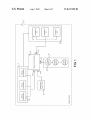
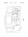
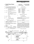
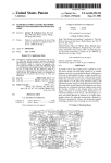
Displayed in FIG. 1 is a block diagram illustrating an
exemplary embodiment of connections betWeen a safety con
links included in the safety control assembly to establish a
physical and electrical connection betWeen the manual and
automation assemblies and corresponding circuits in the
safety control assembly. While the manual assembly connec
60
more manual components 35 included in the manual mode
assembly 15 can correspond to the various electrical and
mechanical assemblies included in the vehicle 5 to enable a
user to operate the vehicle manually. Exemplary manual com
ponents 35 can include, for example: circuitry dedicated to a
fuel shut-off solenoid; a steering motor; and a throttle assem
bly. These components can be poWered and controlled by the
65
automation assembly 20 When the vehicle 5 operates in an
autonomous mode. HoWever, When in a manual mode, the
manual components 35 can be controlled by a user, and poW
ered via a connection With a manual relay 224 included in the
safety control module 10. The manual mode of operation can
alloW a user to operate the vehicle 5 as they Would Without