1
w w w. m g e o p s . c o m
E N G L I S H
E S P A Ñ O L
Pulsar MX Frame
Chasis Pulsar MX
Scalable Up To 20kVA
Escalable hasta 20kVA
Installation and User Manual
Manual de instalación y de usuario
E N G L I S H
Installation and User Manual
Pulsar MX Frame
Installation and User Manual
Revision History
Pulsar MX Frame Installation and User Manual, 86-87021-00
Revision: A00
ECN#: 005122
5/2007
Copyright © 2007 MGE Office Protection Systems
All rights reserved. Printed in U.S.A.
MGE Office Protection Systems
13 Whatney, Suite #101
Irvine, CA 92618
(949) 268-2800
For Technical Support, Customer Care Center, or Customer FAQ,
please visit our website: www.mgeops.com or call (800) 279-7776
86-87021-00 A00
Pulsar MX Frame
E N G L I S H
86-87021-00 A00
E N G L I S H
Contents
Introduction ..........................................................................................................................................1
Important Safety Instructions ..............................................................................................................2
Symbol Usage ....................................................................................................................................3
Presentation
1.1
Pulsar MX 10U Frame Positions ....................................................................................1 — 1
1.2
Pulsar MX 16U Frame Positions ....................................................................................1 — 2
1.3
10U Rear Panel ..............................................................................................................1 — 3
1.4
16U Rear Panel ..............................................................................................................1 — 4
1.5
Display and Control Panel ............................................................................................1 — 5
1.6
Extended Battery (EXB) & Battery Integration System Kit ............................................1 — 6
Installation
2.1
Unpacking and Contents Check for 10U ........................................................................2 — 1
2.2
Unpacking and Contents Check for 16U ........................................................................2 — 2
2.3
Installation of Wheels and Leveling Feet (Shown for 16U Frame) ................................2 — 3
2.4
Installation in Rack (Shown for 16U Frame) ..................................................................2 — 4
2.5
Mounting Sub-Modules (Shown for 16U Frame)............................................................2 — 5
2.6
Communication Ports ....................................................................................................2 — 6
2.7
Required Protective Devices and Cable Cross-Sections .............................................. 2 — 8
2.8
System Installation..........................................................................................................2 — 8
2.9
System Connections of Input/Output Power Cable ........................................................2 — 9
2.10
Extended Battery Connections ....................................................................................2 — 12
Operation
3.1
Initial Start-Up ................................................................................................................3 — 1
3.2
Operating Modes ............................................................................................................3 — 2
3.3
Operation on Battery Power ..........................................................................................3 — 3
3.4
Return to Normal AC Source..........................................................................................3 — 4
3.5
UPS Shutdown When AC Present ................................................................................3 — 4
3.6
UPS Shutdown When on Battery ..................................................................................3 — 4
Access to Maintenance and Personalization Data
86-87021-00 A00
4.1
Display Organization ......................................................................................................4 — 1
4.2
Access to Measurements ..............................................................................................4 — 1
4.3
Access to UPS Set-Up and Maintenance Using the Control Panel ..............................4 — 1
4.4
UPS Set-Up — Personalization......................................................................................4 — 2
4.5
Maintenance ..................................................................................................................4 — 3
4.6
UPS Set-Up Using External Software ............................................................................4 — 3
4.7
Pulsar MX Frame Manual Bypass Switch ......................................................................4 — 4
Contents
ci
Pulsar MX Frame
E N G L I S H
Troubleshooting
5.1
Troubleshooting LEDs (21) and (22) ..............................................................................5 — 1
5.2
Troubleshooting Not Requiring MGE Office Protection Systems After-Sales Support ....5 — 1
5.3
Troubleshooting Requiring MGE Office Protection Systems After-Sales Support ........5 — 2
Life Cycle Monitoring (LCM)
6.1
Description......................................................................................................................6 — 1
Maintenance
7.1
Hot Swapping the Power Sub-Module ...........................................................................7 — 1
7.2
Hot Swapping the Battery Sub-Module .........................................................................7 — 1
Appendices
8.1
Technical Specifications .................................................................................................8 — 1
8.2
Parts List ........................................................................................................................8 — 2
8.3
BTU & Efficiency in Normal, Battery, & Autobypass Mode for 15 & 20kVA ..................8 — 2
Customer Care Center – Single Phase Products
Technical Support and Product Services........................................................................8 — 3
Who to Contact
Scheduling Field Service Engineer Support
Return Policy for Repair of Single Phase Products (RGA)
Glossary ..............................................................................................................................................G — 1
c ii
Contents
86-87021-00 A00
E N G L I S H
Introduction
Thank you for selecting an MGE Office Protection Systems product to protect your electrical equipment.
The Pulsar MX Frame has been designed with the utmost care. The Pulsar MX Frame is scalable with parallel functions to
support loads up to 20kVA in increments of 5kVA per module.
We recommend that you take the time to read this manual to take full advantage of the many features of your UPS (Uninterruptible
Power System).
Warning: This is a class A UPS product. In a domestic environment, this product may cause radio interference, in which case, the
user may be required to take additional measures.
If the device must be installed in overvoltage category III or IV environments, additional upstream overvoltage protection must be
provided for.
Before installing Pulsar MX Frame, please read the booklet on the required safety instructions. Then follow the indications in this
manual.
To discover the entire range of MGE Office Protection Systems products and the options available for the Pulsar MX range, we
invite you to visit our web site at www.mgeops.com or contact your MGE Office Protection Systems at (800) 279-7776.
Environmental protection
MGE Office Protection Systems has implemented an environmental-protection policy.
Products are developed according to an eco-design approach.
Substances
This product does not contain CFCs, HCFCs, or asbestos.
Packing
To improve waste treatment and facilitate recycling, separate the various packing components.
◗ The cardboard we use comprises over 50% of recycled cardboard.
◗ Sacks and bags are made of polyethylene.
01
◗ Packing materials are recyclable and bear the appropriate identification symbol.
PET
Material
Abbreviation
Symbol
number
Polyethylene terephthalate
PET
01
High-density polyethylene
HDPE
02
Polyvinyl chloride
PVC
03
Low-density polyethylene
LDPE
04
Polypropylene
PP
05
Polystyrene
PS
06
01
PET
Follow all local regulations for the disposal of packing materials.
End of life
MGE Office Protection Systems will process products at the end of their service life in compliance with local regulations.
MGE Office Protection Systems works with companies in charge of collecting and eliminating our products at the end of their
service life.
Product
The product is made up of recyclable materials.
Dismantling and destruction must take place in compliance with all local regulations concerning waste.
At the end of its service life, the product must be transported to a processing center for electrical and electronic waste.
◗
Battery
The product contains lead-acid batteries that must be processed according to applicable local regulations concerning
batteries.
The battery may be removed and disposed of in compliance with correct local disposal regulations.
The "Material Safety Data Sheets" (MSDS) for the batteries are available on our web site*.
◗
(*) For more information or to contact the Product Environmental manager, please visit our website: www.mgeops.com.
86-87021-00 A00
Introduction
1
Pulsar MX Frame
E N G L I S H
IMPORTANT SAFETY INSTRUCTIONS
SAVE THESE INSTRUCTIONS. This manual contains important instructions that should be followed during installation and maintenance of the UPS and batteries.
The Pulsar MX Frame models that are covered in this manual are intended for installation in an environment within 0 to 40°C, free
of conductive contaminant.
This equipment has been tested and found to comply with the limits for a Class A digital device, pursuant to Part 15 of the FCC Rules.
These limits are designed to provide reasonable protection against harmful interference when the equipment is operated in a commercial environment. This equipment generates, uses, and can radiate radio frequency energy and, if not installed and used in accordance
with the instruction manual, may cause harmful interference to radio communications. Operation of this equipment in a residential area
is likely to cause harmful interference in which case the user will be required to correct the interference at his own expense.
Certification Standards
◗
◗
◗
◗
◗
◗
◗
◗
◗
◗
IEEE 587-1980/ANSI C62.41 1980 Standards for Surge Withstand Ability
FCC rules and regulations of Part 15, Subpart J, Class A
UL listed under 1778, Standards for Uninterruptible Power Supply Equipment
IEC 61000-4-2 (ESD): level 4
IEC 61000-4-3 (Radiated field): level 3
IEC 61000-4-4 (EFT): level 4
IEC 61000-4-5 (Fast transients): level 4
IEEE-C6241 Category B (ring wave)
IEC 61000-4-6 (electromagnetic field)
IEC 61000-4-8 (conducted magnetic field)
Safety of persons
◗
◗
◗
◗
The system has its own power source (the battery). Consequently, the power outlets may be energized even if the system is disconnected
from the AC power source.
Dangerous voltage levels are present within the system. It should be opened exclusively by qualified service personnel.
The system must be properly grounded.
The battery supplied with the system contains small amounts of toxic materials. To avoid accidents, the directives listed below must be observed:
-Never burn the battery (risk of explosion).
-Do not attempt to open the battery (the electrolyte is dangerous for the eyes and skin).
-Comply with all applicable regulations for the disposal of the battery.
-Batteries constitute a danger (electrical shock, burns). The short-circuit current may be very high. Precautions must be taken for all handling:
remove watches, rings, bracelets and any other metal objects, use tools with insulated handles.
-Do not lay tools or metal parts on top of batteries.
Product Safety
◗
◗
◗
◗
◗
◗
◗
◗
◗
The UPS connection instructions and operation described in the manual must be followed in the indicated order.
A protection circuit breaker must be installed upstream and be easily accessible. The system can be disconnected from the AC power source
by opening this circuit breaker.
Check that the indications on the rating plate correspond to your AC powered system and to the actual electrical consumption of all the
equipment to be connected to the system.
Never install the system near liquids or in an excessively damp environment.
Never let a foreign body penetrate inside the system.
Never block the ventilation grates of the system.
Never expose the system to direct sunlight or source of heat.
If the system must be stored prior to installation, storage must be in a dry place.
The admissible storage temperature range is -20ºC to +40ºC.
Special Precautions
◗
◗
◗
All handling operations will require at least two people (unpacking, installation in rack system).
Before and after the installation, if the UPS remains de-energized for a long period, the UPS must be energized for a period of 24 hours, at least
once every 6 months (for a normal storage temperature less than 25°C). This charges the battery, thus avoiding possible irreversible damage.
During the replacement of the Battery Module, it is imperative to use the same type and number of elements as the original Battery Module provided
with the UPS to maintain an identical level of performance and safety. In case of doubt, don’t hesitate to contact your MGE Office Protection
Systems representative.
Environment
◗
◗
◗
2
This product has been designed to respect the environment:
It does not contain any Chlorofluorocarbon (CFC) or Hydrochlorofluorocarbon (HCFC).
UPS recycling at the end of service life:
MGE Office Protection Systems undertakes to recycle, by certified companies and in compliance with all applicable regulations, all UPS products recovered at the end of their service life (contact your MGE Office Protection Systems, branch office).
Packing: UPS packing materials must be recycled in compliance with all applicable regulations.
WARNING: This product contains lead-acid batteries. Lead is a dangerous substance for the environment if it is not
properly recycled by specialized companies.
Introduction
86-87021-00 A00
E N G L I S H
Installation and User Manual
Symbol Usage
Important instructions that must always be followed
Information, advice, help
Visual indication
Action
Audible signal
LED off
LED on
86-87021-00 A00
Introduction
3
E N G L I S H
Pulsar MX Frame
(This page left blank intentionally)
4
86-87021-00 A00
E N G L I S H
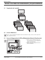
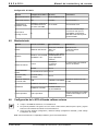
Presentation
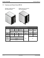
1.1
Pulsar MX 10U Frame Positions
Rack Mount 10U
(Without Wheels) Standard
Rack Mount 10U
(With Wheels) Optional
Pulsar MX Frame 10U Weights and Dimensions
Pulsar MX 10U
Empty Frame
Pulsar MX
10U Frame
5000 VA
Pulsar MX 10U
Frame
10000 VA
Rack Mount
Standard
Part Number
87011
87015
87010
99.2 lbs / 45kg
10U Frame
Dimensions
WxHxD
(inches/mm)
17.5 x 16.7 x 28.2 in / 444.5 x 424 x 716mm
86-87021-00 A00
Pulsar MX
Power
Sub-Module
Pulsar MX
Battery
Sub-Module
87100
87101
25.4 / 11.5
65.0 / 29.5
Optional
Weight (lbs/kg)
10U Frame
Shipping Box
Dimensions
WxHxD
(inches/mm)
Wheel Kit
87410
N/A
N/A
23.2 x 24 x 39.37 in / 589 x 610 x 1000mm
Presentation
1—1
Pulsar MX Frame
1.2
E N G L I S H
Pulsar MX 16U Frame Positions
Rack Mount 16U
(Without Wheels) Standard
Floor Mount 16U
(With Wheels) Option
Pulsar MX Frame 16U Weights and Dimensions
Wheel Kit
Rack Mount
Standard
Optional
Part Number
87021
87415
87420
Weight (lbs/kg)
152/69
423/192
513/233
Frame
Dimensions
HxWxD
(inches/mm)
1—2
Pulsar MX 16U Pulsar MX 16U Pulsar MX 16U
Empty
Frame
Frame
Frame
15000 VA
20000 VA
87410
Pulsar MX
Power
Sub-Module
Pulsar MX
Battery
Sub-Module
87100
87101
25.4/11.5
65.0/29.5
27/688
N/A
17.5/444.5
N/A
29/737.4
Presentation
86-87021-00 A00
E N G L I S H
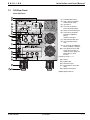
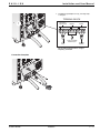
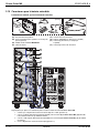
1.3
Installation and User Manual
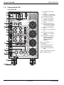
10U Rear Panel
Pulsar MX Frame
1
(1) Manual Bypass switch
2
(2) Slots 1 and 2 for optional
communication cards
4
(3) Input switch
5
(4) Connector for Remote
Power Off control (RPO)
7
(5) RS232 communication port
8
(6) Connector for automatic
detection of additional
battery
modules 1 through 2
3
6
10
9
(7) USB communication port
(8) Communication port by
relay
17
(9) DC connector for additional
battery modules 1 through 2
6
(10) Two groups of two L6-30R
outlets for connection of
equipment (each group of 2
protected by a circuit
breaker)
9
16
15
(11-13) See Page 1 — 6
14
(14) Output
(15) Bypass input
(16) Normal AC input
55
56
(17) PDU output circuit breaker
(30A)
57
(55) Optional leveling feet
(56-57) Optional Wheels
86-87021-00 A00
Presentation
1—3
Pulsar MX Frame
1.4
E N G L I S H
16U Rear Panel
Pulsar MX Frame
(1) Manual Bypass switch
1
(2) Slots 1 and 2 for optional
communication cards
2
(3) Input switch
3
(4) Connector for Remote
Power Off control (RPO)
4
(5) RS232 communication port
(6) Connector for automatic
detection of additional
battery
modules 1 through 4
5
6
7
9
8
(7) USB communication port
(8) Communication port by
relay
10
(9) DC connector for additional
battery modules 1 through 4
6
(10) Four groups of two L6-30R
outlets for connection of
equipment (each group of 2
protected by a circuit
breaker)
9
(11-13) See Page 1 — 6
(14) Output
6
17
(15) Bypass input
(16) Normal AC input
9
(17) PDU output circuit breaker
(30A)
14
(55) Optional leveling feet
15
(56-57) Optional Wheels
6
16
9
55
56
1—4
57
Presentation
86-87021-00 A00
E N G L I S H
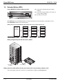
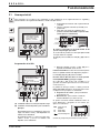
1.5
Installation and User Manual
Display and Control Panel
(20) Load protected LED
(21) Downgraded operation LED
(22) Load not protected LED
(23) Alphanumeric display (4 lines)
LOAD PROTECTED
00.0kVA/000% LOADED
ONLINE MODE
0+4 redundant
(24) Escape (cancel) button
(25) Function button (scroll down)
(26) Function button (scroll up)
(27) Enter (confirm) button
(28) UPS OFF button
(29) UPS ON button
(30) Rectifier LED
(31) Battery LED
(32) Inverter LED
(33) Bypass LED
(34) Load supplied LED
Sub-module symbolic
(1) Sub-module detection
(2) The power sub-module and the battery submodule are not detected on the level (Pulsar
MX Frame 15000 RT)
(3) Internal battery sub-module fault detected
(4) Internal power sub-module fault detected
For internal sub-module fault, see Section 5.2,
Page 5 — 1.
86-87021-00 A00
Presentation
1—5
Pulsar MX Frame
1.6
E N G L I S H
Extended Battery (EXB)
Pulsar MX EXB RT (optional battery module)
(11) Connectors for automatic detection of battery
module(s)
11
(12) Connectors for battery modules (to the UPS or to
the other battery modules)
13
(13) DC Battery circuit breaker
12
Pulsar MX Frame offers a standard backup time of 5 minutes at full load. To increase backup time, it is possible to connect
Pulsar MX EXB RT modules to the Pulsar MX Frame.
Battery extensions for Pulsar MX Frame with backup times up to 62 minutes (at full load)
Pulsar MX
Frame
20000 RT
Pulsar MX 20000 RT:
5 min
Pulsar MX EXB RT
Pulsar MX EXB RT
Pulsar MX EXB RT
Pulsar MX EXB RT
Pulsar MX EXB RT
Pulsar MX EXB RT
Pulsar MX EXB RT
Pulsar MX EXB RT
Pulsar MX EXB RT
Pulsar MX EXB RT
Pulsar MX EXB RT
Pulsar MX EXB RT
41 min
62 min
22 min
Battery Integration System Kit with Casters (86005)
seismic anchors
(included)
caster (included)
Battery extension cable (68528) includes power cable (6 ft/1.8 m) and battery detection cable
This extended battery cable will be used when an extended battery is added to the Pulsar MX Frame.
1—6
Presentation
86-87021-00 A00
E N G L I S H
Installation
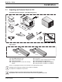
2.1
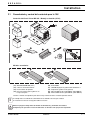
Unpacking and Contents Check for 10U
Pulsar MX 10U Frame Contents – Rack Mounting (87011)
41
46
47
optional
communication cards
Sub-modules
58
59
(87100)
(41)
(42)
(43)
(45)
(87101)
Pulsar MX Frame 10U (empty)
RS232 communications cable
Product documentation
Telescopic rails for rack enclosure with mounting
hardware
(46)
(47)
(48)
(58)
(59)
Screw driver
Solution-Pac 2 power management suite CD-ROM
Network Management cards (optional)
Power sub-module (1 for 5000 VA, 2 for 10000 VA)
Battery sub-module (1 for 5000 VA, 2 for 10000 VA)
Please see the appropriate manual for more information on the optional battery module.
i
Packaging must be destroyed according to waste management standards.
Recycling icons are displayed for easy selection.
A dangerous voltage is present inside the power module and the battery module.
Any operations to be carried out on these modules must be done so by qualified personnel.
86-87021-00 A00
Installation
2—1
Pulsar MX Frame
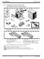
2.2
E N G L I S H
Unpacking and Contents Check for 16U
Pulsar MX 16U Frame Contents – Rack Mounting (87021)
46
47
optional
communication cards
Sub-modules
58
59
(87100)
(40)
(42)
(43)
(45)
(87101)
Pulsar MX Frame 16U (empty)
RS232 communications cable
Product documentation
Telescopic rails for rack enclosure with mounting
hardware
(46)
(47)
(48)
(58)
(59)
Screw driver
Solution-Pac 2 power management suite CD-ROM
Network Management cards (optional)
Power sub-module (3 for 15000 VA, 4 for 20000 VA)
Battery sub-module (3 for 15000 VA, 4 for 20000 VA)
Please see the appropriate manual for more information on the optional battery module.
i
Packaging must be destroyed according to waste management standards.
Recycling icons are displayed for easy selection.
A dangerous voltage is present inside the power module and the battery module.
Any operations to be carried out on these modules must be done so by qualified personnel.
2—2
Installation
86-87021-00 A00
E N G L I S H
2.3
Installation and User Manual
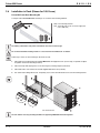
Installation of Wheels and Leveling Feet (Shown for 16U Frame)
The battery sub-modules and power sub-modules must not be mounted yet.
Do not install the UPS or battery module in a closed environment without air circulation.
Follow steps 1 thru 6 for installation of wheels.
1.
Place Pulsar MX Frame on its side.
2.
Install the two fixed-wheels on the back bottom of the unit with the screws provided.
3.
Install the two swivel-wheels on the front bottom of the unit with the screws provided.
4.
Install the four leveling feet.
5.
Return Pulsar MX Frame to upright position.
6.
Attach the two seismic plates.
1
fixed wheels
2
leveling feet
4
5
3
swivel
wheels
56
57
55
optional
(87410)
6
63
16U Frame shown
86-87021-00 A00
Installation
2—3
Pulsar MX Frame
2.4
E N G L I S H
Installation in Rack (Shown for 16U Frame)
Pulsar MX Frame Rack Mounting Kit
Telescopic rails for Pulsar MX Frame mounting in 19’’ enclosure with mounting hardware
(35) Front mounting brackets
(37) Telescopic rails, 27.36’’ to 39.96’’ length (639
mm to 1005 mm)
The battery sub-modules and power sub-modules must not be mounted yet.
Do not install the UPS or battery module in a closed environment without air circulation.
Follow steps 1 thru 4 for rack mounting the UPS onto the rails.
1.
Attach both front mounting brackets to Pulsar MX Frame with supplied screws. (For this step, it is possible to adjust
the position of both front mounting brackets.)
2.
Attach telescopic rails (37) together, secure with wing nuts, and finger tighten (both sides).
3.
Attach both rails to rear and front of rack with supplied flathead screws (as shown).
4.
Use caution when sliding unit into rack. Temporarily secure unit to rack with thumb screws on front mounting brackets.
16U Frame shown
The rails and the necessary mounting hardware are supplied by MGE Office Protection Systems.
2—4
Installation
86-87021-00 A00
E N G L I S H
2.5
Installation and User Manual
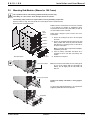
Mounting Sub-Modules (Shown for 16U Frame)
This operation must be carried out by qualified electrical personnel only.
The battery can cause electric shock and high short-circuit currents.
The following safety cautions are required before servicing the battery components:
◗ Remove watches, rings, bracelets and all other metal objects from the hands and arms,
◗ Use tools with an insulated handle.
Modules must be mounted from the lowest level (module
1) to the highest level (module 4), installing the power
sub-module first and the battery sub-module second. All
the sub-modules must be mounted.
main
control
panel
Follow steps 1 through 4 below to mount each of the
sub-modules.
module 4
module 3
module 2
6”
module 1
1. Remove the 6 fixing screws to free the front panel
as shown.
2. Remove the mounting brackets from the power and
battery module slots. Insert the power sub-module
and attach the 4 mounting screws on each side of
the power sub-module.
Note: A red button will be depressed behind plate,
establishing connection.
1.
front panel
16U Frame shown
power sub-module
3. Insert the battery sub-module and attach the 4
mounting screws on each side of the battery submodule.
4. Reattach the front panel.
Note: For removal of a sub-module, there is a safety pin at
the rear of the module. Slide the sub-module out
halfway, then lift slightly and the sub-module will
slide out.
2.
battery sub-module
Caution! The battery sub-module is heavy (approx.
60 lbs.).
To ensure safety and high performance, use only batteries
supplied by MGE Office Protection Systems.
3.
front panel
4.
86-87021-00 A00
Installation
2—5
Pulsar MX Frame
2.6
E N G L I S H
Communication Ports
Pulsar MX Frame provides 4 communication methods.
1.
The RS232 port provides communications using MGE Office Protection Systems Serial HID UPS transfer (SHUT)
protocol. The SHUT protocol is compatible with the power management applications available on the enclosed
Solution-Pac 2 CD-Rom.
2.
The Output contacts port is used for basic signaling or for protection of IT systems like IBM iSeries (formerly AS400)
and more.
3.
The USB port is compatible with the power management applications available on the enclosed Solution-Pac 2 CD-Rom.
4.
The two slots are compatible with the optional 66102 – Network Management Card (NMC) 2006 Edition, and the
66104 – Management Card Contact and RS232/Serial.
Note: All communications options can be used simultaneously except for the SHUT RS232 and USB port. If both the USB
and SHUT ports are connected, then the USB takes control.
Connection to the RS232 or USB communication port (42)
1. Connect the RS232 (42) cable to the serial port
on the computer equipment, or connect a USB (44)
communication cable (not provided by MGE Office
Protection Systems) to the USB port on the
computer equipment.
2. Connect the other end of the RS232 cable (42) to
the RS232 (5) communication port, or connect the
USB cable (not provided by MGE Office Protection
Systems) to the USB port (7) on the UPS.
The UPS can now communicate with various MGE Office
Protection Systems power management application
software.
Please note that Personal Solution-Pac can be used to
configure (personalize) the UPS parameters such as
voltage, frequency, battery test, etc. See Section 4.6 for
more details.
Connection to the communication port by relays (8)
◗ Pin 1: Major Alarm
◗ Pin 2: Battery Fault
◗ Pin 3: Remote Power Off signal (5 to 27 V DC,
10 m A max),
◗ Pin 4: Operation on mains (not on battery),
◗ Pin 5: User common,
◗ Pin 6: Operation on automatic by-pass,
◗ Pin 7: Low battery,
◗ Pin 8: Load protected,
◗ Pin 9: Operation on battery.
n.o:
contact normally open.
8
When the status is active, the contact between the common (Pin 5) and the relevant information pin is closed.
Output relays specifications:
◗ Voltage: 48 V DC max,
◗ Current: 2 A max,
◗ Power: 62.5 VA, 30 W.
Example: for 48 V DC, Imax=625 mA
2—6
Installation
86-87021-00 A00
E N G L I S H
Installation and User Manual
Installation of optional communication cards (66102/66104/66846)
Consult MGE Office Protection Systems for communication cards.
It is not necessary to shutdown the UPS before
installing a communications card.
1. Remove the slot cover(s) secured by two screws.
2
2. Insert the optional communication card(s) (48) in
the slot(s) (2).
3. Secure the card(s) with both screws.
Remote Power Off communication port (9)
Installation of a Remote Power Off function must be carried out in compliance with applicable regulations.
In order to fully de-energize Pulsar MX Frame with the RPO port, it is necessary to use a two-position switch (Normally
Open or Closed contact). Once switch is energized/de-energized, the UPS shuts off the display and the output of the UPS.
◗
◗
The output devices can be powered again through auto bypass when the two-position switch is released (open or closed).
The output devices will remain powered < 1 sec. after RPO activation.
Push the start button to return to normal operation.
Note: The internal batteries will remain connected to the power sub-module after RPO activation.
The cable is not included.
Remote power off contact normally open (9)
Remote power off contact normally closed (9)
RJ12
RJ12
+
5 VDC to 27 VDC
+
5 V DC to 27 V DC
_
_
◗ Signal:
activation voltage: 5 V DC to 27 V DC,
current: 10 mA max.
86-87021-00 A00
Installation
2—7
Pulsar MX Frame
2.7
E N G L I S H
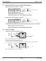
Required Protective Devices and Cable Cross-Sections
Recommended upstream protection – 16U Frame
2 poles circuit breaker
UPS Power Rating
Upstream Circuit
Breaker
15000/20000 VA
L1
To UPS Normal AC source
L2 (N)
125 A
G L2 (N) L1
Required cable cross-sections 16U Frame
◗ Terminal-block cable capacity: 25 mm2, solid or stranded wire (maximum AWG 2).
◗ Capacity for ground conductor: 25 mm2, solid or stranded wire (maximum AWG 2).
Recommended upstream protection – 10U Frame
UPS Power Rating
2 poles circuit breaker
Upstream Circuit
Breaker
5000/10000 VA
L1
To UPS Normal AC source
L2 (N)
60 A
G L2 (N) L1
The indicated protection ensures discrimination for each output circuit downstream of the UPS. If these recommendations are
not followed, protection discrimination is not achieved and may result in a potential power interruption to the connected devices.
Required cable cross-sections 10U Frame
◗ Terminal-block cable capacity: 13 mm2, solid or stranded wire (maximum AWG 6).
◗ Capacity for ground conductor: 13 mm2, solid or stranded wire (maximum AWG 6).
2.8
System Installation
UPS with Common Normal and Bypass AC inputs
Bypass AC
Main lowvoltage
switchboard
(MLVS)
Factory Installed
Metal Jumper
A
Load
Normal AC
Note: If using this configuration, do not remove the metal jumper (A).
Frequency converter (without Bypass AC input)
Configuration used when the frequency of the application differs from the Mains (Example: marine requirements).
Main lowvoltage
switchboard
(MLVS)
Remove the
Factory Installed
Metal Jumper
A
Load
Normal AC
Note: If using this configuration, remove the metal jumper (A).
2—8
Installation
86-87021-00 A00
E N G L I S H
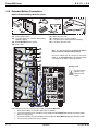
2.9
Installation and User Manual
System Connections of Input/Output Power Cables
This type of connection must be carried out by qualified electrical personnel.
Before making any connections, check that the upstream protection device (Normal AC source) is open "0" (OFF).
To access the connection terminal blocks, see Section 1.2, Rear Panel:
Input Connection
Always connect the ground cable first.
D
20
0-25
~,24
0V
2
Y
ER N
TT IO
BA CT
TE
DE
Byp
1
No
rm
al
L2
AC
(N
)
So
A
t
tpu
L1
Ou
)
(N
L2
rce
u
So 1
L
ass
)
(N
L2
e
urc
L1
1. Remove the terminal block cover (2 screws).
L1
1
Y
ER N
TT IO
BA CT
TE
DE
2. Remove the 2 screws as shown in step 2 and
knockout for input and output.
BA CT
TE
DE
20
Y
ER N
TT IO
BA CT
TE
DE
2
0-25
e
urc
So 1
L
ass
Byp 2(N)
L
2
No
rm
al
AC
(N
L2
)
So
~,24
0V
A
t
tpu 1
L
Ou
)
(N
L2
e
urc
L1
L1
1
Y
ER N
TT IO
BA CT
TE
DE
knockouts
86-87021-00 A00
Installation
2—9
Pulsar MX Frame
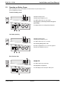
E N G L I S H
Access to terminal block
2 — 10
3
3. Pull up the moving tray.and insert the Normal AC
input/output cables/conduit through knockout.
4
4. Pull out the moving tray.
5
5. Pull down the moving tray.
6
6. Connect the 3 cables to the Normal AC
input/output AC terminal block.
Installation
86-87021-00 A00
E N G L I S H
Installation and User Manual
7. Reinstall the input/output cover by reversing steps
1 through 5.
20
2
Y
ER N
TT O
BA ECTI
DET
By
7
No
rm
al
AC
(N
L2
)
So
u
S
ss
ou
pa
)
(N
L2
0-25
rce
L1
~,24
0V
A
TERMINAL BLOCK
t
tpu 1
L
Ou
)
(N
L2
Normal AC
Input Source
rce
L1
L1
L2(N) L1
Bypass
L1
L2(N) L1
Output
L2(N) L1
1
Y
ER N
TT O
BA ECTI
DET
A
From
Utiity
Factory Installed
Metal Jumper
To Load
208VAC
Do not remove jumper unless using as
frequency converter!
Connection Complete
20
0-25
e
urc
So 1
ss
L
pa
By 2(N)
L
2
Y
ER N
TT O
BA ECTI
DET
No
rm
al
L2
AC
(N
)
So
~,24
0V
A
t
tpu 1
L
Ou
)
(N
L2
e
urc
L1
L1
1
Y
ER N
TT O
BA ECTI
DET
86-87021-00 A00
Installation
2 — 11
Pulsar MX Frame
E N G L I S H
2.10 Extended Battery Connections
Optional Extended Battery Module Contents
50
(87103)
52
(68528)
61
53
45
54
43
(43) Product documentation
(45) Telescopic rails for rack enclosure with mounting
hardware (optional)
(50) Pulsar MX EXB RT battery module
(52) Battery cable
(53)
(54)
(61)
(62)
62
Battery detection cable
Stabilizer bracket (4 screws included)
Long battery power cable (purchased separately)
Long battery detection cable
11
Note: It is not necessary to shutdown the UPS in
order to install the extended battery module.
13
Up to three batteries may be connected to each power
module on the Pulsar MX Frame. The illustration shows
connections for two battery cabinets per module.
12
52
53
Shown for 16U
62
61
One EXB must be
added for each
5kVA power sub
module.
6
9
Follow steps below for connecting one battery module to the Pulsar MX Frame.
1.
2.
4.
5.
2 — 12
Check that the battery circuit breaker (13) is OFF (”0” position).
Connect the long battery power cable (61) to connectors (9) of the Pulsar MX Frame and (12) of the battery module,
and secure using screws.
Connect the long battery detection cable (62) to connectors (6) of the Pulsar MX Frame and (11) of the battery module.
Close the battery circuit breaker (13) (“I” position).
Installation
86-87021-00 A00
E N G L I S H
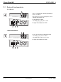
Operation
3.1
Initial Start-Up
To ensure that your system is configured in complete accordance with safety regulations and to benefit from the
manufacturer’s warranty, please contact Technical Support.
1. Bypass switch is in normal position and locked.
22
2. Set the upstream circuit breaker (not included) to
the ON position.
3. Turn input switch on the rear panel of the Pulsar
MX Frame to the ON position (as shown below).
LOAD UNPROTECTED
00.0 KVA/00% LOADED
ON AUTO BYPASS
PRESS ( I ) to START
Slot 1
Slot 2
Input
Switch
Bypass
Switch
Input
Switch
4
BATTERY
DETECTION
The equipment is powered via the Normal AC source,
but not protected by the UPS.
An 8 hour recharge period is recommended to get full
battery backup time.
33
LED (22) is ON, LEDs (33) and (34) are green.
34
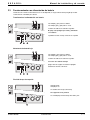
UPS Set-Up
20
21
22
4. Press and hold the "I" (ON) button (29) for 3
seconds. The buzzer beeps once.
Pulsar MX Frame performs an internal test sequence.
Display will show “self diagnosis in progress...”. LEDs
(20), (30), (32), (34) are on.
LOAD PROTECTED
00.0kVA/000% LOADED
ONLINE MODE
1 UPS +3 UPS redundant
A
The Pulsar MX Frame is now in normal operating mode
(ONLINE MODE) and the equipment is protected.
If LED (21) or (22) is ON, an alarm has occurred (for
troubleshooting, see Section 5.1).
The screen at start-up shows overall status of the Pulsar
MX Frame. Scroll down to access either menu below:
B
◗ UPS Set-Up – for personalization (see Section 4.4)
◗ Maintenance – to monitor status of individual
modules (see Section 4.5)
30
32
34
Individual modules may be selected within the
“Maintenance” menu by navigating with the buttons below:
29
(A) Number of modules required to support the load
(B) Number of modules available for redundancy
Examples:
If the display indicates 1+3 (redundancy) then the
load is 5kVA or less and three modules are available
for redundancy.
ESC back one screen
▼
scroll down
▲
scroll up
select/enter
XXXXXXXX
XXXXXXXX
XXXXXXXX
XXXXXXXX
See Section 4.1 for display hierarchy.
If the display indicates 3+1, then the load is 15kVA
or less and one module is available for redundancy.
86-87021-00 A00
Operation
3—1
Pulsar MX Frame
3.2
E N G L I S H
Operating Modes
Normal mode
This is the standard operating mode, set by default in
the factory.
Under normal conditions (Normal AC source available):
LED (20) is ON.
LEDs (30), (32), and (34) are green.
The equipment is protected by the UPS.
AC out of tolerance
If normal AC source is out of tolerance:
LEDs (20), and (21) are ON.
LEDs (30), (32), and (34) are green.
The equipment is protected by the UPS.
3—2
Operation
86-87021-00 A00
E N G L I S H
3.3
Installation and User Manual
Operation on Battery Power
When the Normal AC source is not available, the load continues to be protected by the UPS.
Power is supplied by the battery.
Transfer to battery power
LEDs (20), and (21) are ON.
LEDs (31), (32), and (34) are green.
The audible alarm beeps every 10 seconds.
The equipment is protected by the UPS and supplied
by the battery.
The display indicates the remaining battery backup time.
Low battery warning
LEDs (20), and (21) are ON.
LEDs (31), (32), and (34) are green.
The audible alarm beeps every 3 seconds.
The remaining battery power is low.
Shut down all applications on the connected equipment.
Automatic UPS shutdown is imminent.
End of backup time
LED (22) is ON.
LED (34) is red.
The audible alarm beeps continuously.
The equipment is not powered.
The UPS displays "End of backup time Battery low".
86-87021-00 A00
Operation
3—3
Pulsar MX Frame
3.4
E N G L I S H
Return to Normal AC Source
After an outage, the UPS restarts automatically when Normal AC source is restored (unless this function has been disabled
via UPS personalization) and the load is supplied again. If function is disabled, see Section 3.1, Initial Start-Up.
3.5
UPS Shutdown When AC Present
Before shutdown, please read ALL instructions below:
22
1. Press and hold the "0” (OFF) button (28) for 3
seconds. The buzzer beeps once.
The load is no longer protected by the UPS. It is
powered via the Normal AC source (bypass). If the UPS
is set in frequency converter mode, the equipment
will not be powered. If the Normal AC source is out of
tolerance, the UPS will generate a 10ms output
calibrated break.
LOAD UNPROTECTED
00.0 KVA/00% LOADED
ON AUTO BYPASS
PRESS ( I ) to START
LEDs (22) is ON. LEDs (33) and (34) are green.
For a full shutdown of UPS and connected load, turn off
the upstream circuit breaker (not included), or remove
the Normal AC source. Turn off the input switch.
33
3.6
34
28
UPS Shutdown When on Battery
Before shutdown, please read ALL instructions below:
1. Press and hold the "0” (OFF) button (28) for 3
seconds. The buzzer beeps once.
2. The display asks for confirmation – “ARE YOU
SURE?”.
3. Press the scroll button (25) to select yes.
“ARE YOU SURE?”
NO
YES
25
3—4
4. Press confirm button (27).
The UPS is now fully shut down.
27 28
Operation
86-87021-00 A00
E N G L I S H
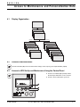
Access to Maintenance and Personalization Data
4.1
Display Organization
Status and Alarms
Measurements
UPS input measurements
UPS output measurements
Battery measurements
UPS Set-up
Local settings
Maintenance
Model
Output settings
Measures (per module)
Redundancy Mode
Redundancy Level
(1 UPS, 2 UPS, 3 UPS)
ON/OFF settings
Battery settings
Alarm History
Install Diagnosis
Manual battery test
Led and Buzzer test
LCM
Statistics
Operation limits
4.2
Access to Measurements
Press the scroll button (25) to access measurements for voltage, current, frequency, power output and battery capacity.
4.3
Access to UPS Set-Up and Maintenance Using the Control Panel
◗ Press the scroll button (25) repeatedly until the
UPS Set-Up or Maintenance menu is reached.
◗ Press the “Enter” button (27) to get access.
86-87021-00 A00
Access to Maintenance and Personalization Data
4—1
Pulsar MX Frame
4.4
E N G L I S H
UPS Set-Up — Personalization
Local Settings
Function
Factory Setting
Options
Language
English
French, German, Italian, Portuguese, Spanish
Date/Time Format
US (MM-DD-YYYY/
HH:MM AM/PM)
International format (DD-MM-YYYY/HH:MM)
Date/Time Change
GMT + 8
MM-DD-YYYY/HH:MM adjustable
Audible Alarm
Yes
No
Function
Factory Setting
Options
Output Voltage
208V
200V / 220V / 230V
240V / 250V
Frequency Converter
Disabled
Enabled
Bypass is disabled
Output Frequency
60 Hz
50 Hz
User selectable under frequencyconverter mode
Slew rate
0.5 Hz/sec.
0.5 Hz/sec.
Bypass Transfer
No
Yes
Transfer to bypass if Normal AC
source is out of tolerance
Interrupt Time
10 ms
20 ms, ...... , 200 ms
Break time calibration during load
transfer on Normal AC source out
of tolerance
105%
40%, 50%, 70%
Alarm if threshold is overrun
Function
Factory Setting
Options
Comments
Cold Start
Disabled
Enabled
Start on battery
Output Settings
Overload Prealarm
Comments
ON/OFF Settings
4—2
Forced Reboot
Enabled
Disabled
Enables automatic restart of the
system even if Normal AC source
is restored before the end of the
shutdown sequence
Auto Restart
Enabled
Disabled
UPS restarts automatically when
Normal AC source is restored
Energy Saving
Disabled
Enabled
Automatic shutdown on battery if
output load level < 10%
Remote Command
Enabled
Disabled
Enables consideration of
shutdown or restart orders from
software to be authorized
Access to Maintenance and Personalization Data
86-87021-00 A00
E N G L I S H
Installation and User Manual
Battery Settings
Function
Factory Setting
Options
Auto Battery Test
Every week
No test / daily / monthly
Low Battery warning
20%
0 to 100%
1% increment
User Battery Settings
UPS reads number of
battery modules
connected
From 0 to 40 Ah
5 Ah increment
Yes
No
Protection against deep
discharge. If disabled, MGE
Office Protection Systems
warranty will be void
Function
Sub-Function
Option/Display
Comments
Model
Power Module
SN: xxxxxxxxx
SOFT: xxx
NT: xxx
Serial number
Soft version
Technical level
Measurement
Monitoring by selecting
Modules 1 through 4
Status for each module:
Input/Output
kVA to load
Battery capacity
Read
Description
Date Hour
Alarm xxx
Erase
No / Yes
Manual Battery Test
Manual Battery Test
No / Yes
LED & Buzzer Test
LED & Buzzer Test
No / Yes
Life Cycle Monitoring
LCM
Enable / Disable
Auto Statistics
Statistics
Custom Statistics
Reset Date: No, Yes
Statistics
Deep Discharge
Protect
4.5
Maintenance
Alarm History
Statistics
Operation Limits
4.6
Comments
Operation Limits
10 alarms can be stored
automatically
Life Cycling Monitoring alarms
Automatic alarms displayed when
UPS is operating near the limits
UPS Set-Up Using External Software
◗
Insert Solution-Pac CD-ROM in the drive.
◗
On the first navigation screen, select "Point to Point solution" and follow the instructions on how to install the
Personal Solution-Pac software.
◗
Then select "Settings", "Advanced settings", and "UPS settings".
Note: This feature is only supported through Windows and the RS232 communication.
86-87021-00 A00
Access to Maintenance and Personalization Data
4—3
Pulsar MX Frame
4.7
E N G L I S H
Pulsar MX Frame Manual Bypass Switch
This operation must be carried out by a qualified service technician.
Before any action on the manual bypass switch (1), always follow the sequence of operations below.
In Normal operations, the manual bypass switch is in the “Normal” position.
Note: Front panel display: LED (20) is on. LEDs (30), (32), and (34) are green.
Rear View of Pulsar MX
BYPASS position:
1
(See page 1-2
for item numbering.)
3
1. Press and hold the (0) (OFF) button (28) for 3
seconds. The buzzer beeps. The load is powered
via the Normal AC Source (bypass mode).
LED (22) is on. LEDs (33) and (34) are green. See
Page 3-1 for description of the front display LEDs.
2. Unlock the Manual Bypass Switch (1) and set to the
Bypass position. The load is supplied directly with
Normal AC source via the manual bypass switch.
3. Pull red padlock in the center of the manual bypass
switch (1) to lock into Bypass position.
4. Turn off the input switch (3) and all LEDs on the
front display are off.
5. The Pulsar MX Frame is now ready for service.
The Manual Bypass Switch enables service to be
performed on components within the Pulsar MX Frame
without affecting the connected load or the HotSwap
function.
Front Display
Return to NORMAL position:
6. Set the manual bypass switch (1) to Normal
position.
7. Turn ON the input switch (3). The load is powered
via the Normal AC source, but not protected by the
UPS. It is also possible to fully test the Pulsar MX
modules before the manual bypass switch (1) is set
on Normal position.
Front Display
8. Press and hold the "I" (ON) button (29) for 3
seconds. The buzzer beeps. Pulsar MX Frame
performs an internal test sequence. Display will
show “self diagnosis in progress”. LED (20) is ON.
LEDs (30), (32), and (34) are green. No failure has
been detected. The Pulsar MX Frame is now in
normal operating mode (ONLINE MODE) and the
load is protected. If LED (21) or (22) is ON, an alarm
has occurred (see the “troubleshooting” section).
TEST position:
1. Set the manual bypass switch (1) to Test position
2. Press and hold the "I" (ON) button (29) for 3 seconds. The buzzer beeps. Display will show “self diagnosis” and ask for
testing entire UPS or an individual module. If you select entire UPS, the UPS internal test will be launched. If you select an
individual module, you will need to select the desired module and the internal test will be launched. After an Internal test, if
no failure has been detected, LED (22) is ON, and LEDs (30) and (32) are green.
To return to normal operation:
Press and hold the (0) OFF button (28) for 3 seconds. Set the manual bypass switch (1) to Normal position, then follow step
8 above.
4—4
Access to Maintenance and Personalization Data
86-87021-00 A00
E N G L I S H
Troubleshooting
5.1
Troubleshooting LEDs (21) and (22)
If LED (21) is ON:
The equipment is protected by the UPS but the
operation is downgraded (UPS on battery mode or
environmental fault occurs).
If LED (22) is ON:
The equipment is no longer protected by the UPS.
5.2
Troubleshooting Not Requiring MGE Office Protection Systems
After-Sales Support
ENVIRONMENT FAULT
0+4 redundant
27
Press the "Enter" button (27) to display the details below:
Display
Description
Corrective Action
NO BATTERY
The battery is incorrectly connected.
Check battery connections (see Section 2.9).
I/O BAD CONNECTION
AC source is not connected to the
correct terminals.
Check AC wiring.
NO POWER MODULE
The power sub-module is not
inserted.
Check power sub-module connections
(see Section 7.1).
NO BATTERY MODULE
The battery sub-module is
incorrectly connected.
Check battery connections (see Section 7.2).
INV. THERM OVERLOAD
The UPS shuts down automatically
because of a major overload.
Check the power drawn by the connected devices
and disconnect any non-priority devices.
INVERT LIMITATION
Short circuit conditions on output
devices.
Check the installation at the UPS output (wiring, fault
equipment).
86-87021-00 A00
Troubleshooting
5—1
Pulsar MX Frame
5.3
E N G L I S H
Troubleshooting Requiring MGE Office Protection Systems
After-Sales Support
LOAD UNPROTECTED
00.0kVA/000% LOADED
xxx FAULT
0+4 redundant
27
Display
Description
Corrective Action
POWER MODULE FAULT
The power module is incorrectly conCall the after-sales support department at
nected. Internal power sub-module
1-800-279-7776. Follow the power sub-module
fault detected. Use "Enter" button (27)
replacement procedure (see Sections 7.1 and 7.2).
to display details.
Battery fault detected during the batBATTERY MODULE FAULT tery test. Use "Enter" button (27) to
display details.
FRAME FAULT
Internal chassis fault detected. Use
"Enter" button (27) to display details.
Call the after-sales support department at
1-800-279-7776. Follow the battery sub-module and
battery module replacement procedure
(see Section 7.2) .
Call the after-sales support department at
1-800-279-7776.
Note: In case of multiple fault, press the "Enter" button (27) and the scroll button (25) to get access to further details.
5—2
Troubleshooting
86-87021-00 A00
E N G L I S H
Life Cycle Monitoring (LCM)
6.1
Description
This function, embedded in the UPS, displays messages on screen, and communication channels, at every important stage
of the UPS’s life, allowing you to receive free offers, secure your installation power continuity, and reset or disable LCM.
LOAD PROTECTED
00.0kVA/000% LOADED
LCM WARNING
0+4 redundant
Secure your installation power continuity
Anticipate needed maintenance actions thanks to automatically displayed warnings:
LCM Warning Details
Description
BATTERY CHECK
RECOMMENDED.
CONTACT:
www.mgeops.com
Battery is approaching its reliable end of life.
Risk of dramatically reduced backup time.
Reset or disable LCM
In case of any LCM messages displayed:
◗
◗
For temporary reset: Press ESC (25) for 3 seconds in the Status and Alarm screen, to temporarily cancel the alarm
status. The alert will be repeated twice in 30 days.
For permanent reset: Press ENT (27) for 3 seconds in the LCM warning screen, to permanently cancel this LCM event.
At any time:
To disable all LCM messages select "disable all", in LCM menu with LCD navigation.
You will not be aware of any LCM events that can happen on the UPS if you disable all LCM messages.
86-87021-00 A00
Life Cycle Monitoring (LCM)
6—1
Pulsar MX Frame
E N G L I S H
(This page left blank intentionally)
6—2
Life Cycle Monitoring (LCM)
86-87021-00 A00
E N G L I S H
Maintenance
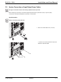
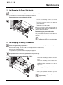
7.1
Hot Swapping the Power Sub-Module
This operation must be carried out by qualified electrical personnel only.
This operation can be performed without interrupting the equipment.
Disconnecting the power sub-module (87100):
1. Remove the 6 mounting screws to free the front
panel, as shown.
2. Remove the 2 mounting screws on each side of the
power sub-module.
3. Withdraw the power sub-module.
2.
Note: There is a safety pin at the rear of the module. Lift
the sub-module slightly and the sub-module will slide out
(follow the arrow in the diagram).
3.
2.
Reconnecting the power sub-module:
Carry out the above instructions in reverse order. A red
button will be depressed behind plate 3, reestablishing
connection.
1.
Replace the faulty power sub-module with a
new module having the same power rating.
7.2
Hot Swapping the Battery Sub-Module
The battery can cause electrocution and high short-circuit currents. The following safety cautions are required
before servicing the battery components:
◗ Remove watches, rings, bracelets and all other metal objects from the hands and arms,
◗ Use tools with an insulated handle.
This operation can be performed without interrupting the equipment.
This operation must be carried out by qualified electrical personnel only.
Disconnecting the battery sub-module (87101):
1. Remove the 6 mounting screws to free the front
panel.
2. Remove the 4 mounting screws on sides of the
battery sub-module.
3.
3. Withdraw the battery sub-module. See note on
Page 2 — 4.
2.
Reconnecting the battery sub-module:
Carry out the above instructions in reverse order.
To ensure safety and high performance, use only
batteries supplied by MGE Office Protection Systems.
Caution! The battery is heavy
(approx. 60 lbs.).
1.
86-87021-00 A00
Maintenance
7—1
Pulsar MX Frame
E N G L I S H
(This page left blank intentionally)
86-87021-00 A00
E N G L I S H
Appendix
8.1
Technical specifications
Pulsar MX Frame
5,000/10,000/15,000/20,000 VA
Output power
Electrical supply network
◗ Rated input voltage
◗ Input voltage range
◗ Frequency
◗ Power factor
◗ Leakage current
Load output
◗ Voltage
◗ Frequency
◗ Harmonic distortion
◗ Overload capacity
Battery sub-module
Pulsar MX EXB
5,000 VA / 4,500 W /
10,000 VA (1) / 9,000 W / (2)
15,000 VA / 13,500 W
20,000 VA (1) / 18,000 W (2)
Single phase 208 V
120/156 V to 280 V (3)
50/60 Hz (autoselect)
> 0.99
20 mA max
Single phase 208 V ±3% (4)
50/60 Hz ±0,5% (5)
< 3%
105% continuous, 110% 2min, 125% 1min, > 150% 0.5s
Battery sub-module contains
15 x 12 V – 5 Ah
sealed lead acid,
maintenance free batteries
Environment
◗ Operating temperature range
◗ Relative humidity
◗ Storage temperature range
◗ Altitude
◗ Noise level
Two battery sub-modules
contain
15 x 12 V – 5 Ah
sealed lead acid,
maintenance free
batteries each
0°C to 40°C
20% to 90% (non-condensing)
-25°C to 40°C
1000 m
< 51 dBA
(1) If the output voltage is 200V — 250V, the output power is 20,000VA / 18,000W.
(2) With one EXB module or more, the standard output power is 10,000VA / 8,000W (for 10U) and 20,000VA /
16,000W (for 16U).
(3) Values for 70% / 100% of UPS load output.
(4) Programmable: 200V / 208V / 220V / 230V / 240V / 250V using the Personal Solution-Pac software.
(5) Frequency-converter mode is programmable using the Personal Solution-Pac software.
86-87021-00 A00
Appendix
8—1
Pulsar MX Frame
8.2
8.3
E N G L I S H
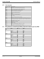
Parts List
Part Number
Description
66102
Network Management Communication Card*
66104
Management Card Contact & RS232/Serial*
66846
Environmental Sensor (66102 required)*
87100
Power sub-module
87101
Battery sub-module
87103
EXB
87316
RS 232 Communication cable
87318
CD – Rom
87418
Rail Kits for Rack mount
68528
Battery power cable & detection cable for 16U & 10U (1.8 m)
87410
4-adjustable, 2-swivel, 2-fixed wheels caster with seismic plates
87411
NEMA type – PDU 1 & PDU 2
66931
Solution Pac 2 & Cable
87011
10U Frame
87306
Sealed lead acid battery, 12V - 5.5 Ah
86005
Battery Integration/Caster Kit only
BTUs & Efficiencies in Normal, Battery, & Autobypass Modes for 15 & 20kVA
Mode
Efficiency
BTU/hr
Normal
91%
1519
Battery
88%
2094
Autobypass
97%
475
Normal
91%
3038
Battery
88%
4189
Autobypass
97%
950
Normal
91%
4557
Battery
88%
6283
Autobypass
97%
1425
Normal
91%
6076
Battery
88%
8377
Autobypass
97%
1900
5kVA
10kVA
15kVA
20kVA
8—2
Appendix
86-87021-00 A00
E N G L I S H
Installation and User Manual
MGE Office Protection Systems
Customer Care Center
Technical Support and Product Services
?
Technical questions? If you encounter a problem while following the instructions in this manual, or have questions
about the operation, repair, or servicing of your equipment, please visit our web site www.mgeops.com or call (800)
279-7776 for complete service information.
To insure that your questions are correctly answered, please obtain the part number, assembly number, and serial number of
the unit and include them in any discussions or correspondence.
Part Number: ________________________________________________________________________________________
Assembly Number: __________________________________________________________________________________
Serial number: ______________________________________________________________________________________
Who To Contact
For Technical Support, Customer Care Center, Customer FAQ please visit our website: www.mgeops.com or call (800) 279-7776
Scheduling Field Service Engineer Support
Scheduling of the MGE Office Protection Systems Field Service Engineers typically should be done 7 to 10 days before they
are required on-site. If the startup of the UPS is critical to maintaining your schedule, please contact MGE Office Protection
Systems, to insure a safe installation and start-up that will maintain the MGE Office Protection Systems warranty and insure
smooth performance.
Return Policy for Single Phase Products (RMA)
Should you require factory service for your equipment, contact MGE Office Protection Systems Customer Care Center and
obtain a Return Materials Authorization (RMA) prior to shipping your unit. Never ship equipment to MGE Office Protection
Systems without first obtaining an RMA number.
For further details please visit our website: www.mgeops.com or call (800) 279-7776
Date: ______________________________________________________________________________________________
RMA Number: ______________________________________________________________________________________
Contact Name: ______________________________________________________________________________________
86-87021-00 A00
Appendix
8—3
Pulsar MX Frame
E N G L I S H
(This page left blank intentionally)
8—4
86-87021-00 A00
E N G L I S H
Glossary
Backup time
Length of time connected equipment can operate on battery power.
Bypass AC source
Source supplying the bypass line. The equipment can be transferred to the bypass line if an
overload occurs on the UPS output, for maintenance or in the event of a malfunction.
Equipment
Devices or systems connected to the UPS output.
Frequency converter
Operating mode used to convert the AC-power frequency between the UPS input and output
(50 Hz – 60 Hz or 60 Hz – 50 Hz).
Load
Devices or systems connected to the UPS output.
Low-battery warning
This is a battery-voltage level indicating that battery power is low and that the user must take
action to prevent the imminent break in the supply of power to the load.
Normal AC source
Normal source of power for the UPS.
Normal (double
conversion) mode
The normal UPS operating mode in which the AC source supplies the UPS which in turn
supplies the connected equipment (after electronic double conversion).
Personalization
It is possible to modify certain UPS parameters set at the factory. Certain UPS functions can
also be modified by the MGE Office Protection Systems power management products to better suit user needs.
Relay contacts
Contacts supplying information to the user in form of signals.
UPS
Uninterruptible Power System.
86-87021-00 A00
Glossary
G—1
E S P A Ñ O L
Manual de instalación y de usuario
Chasis Pulsar MX
Manual de instalación y de usuario
Historial de revisiones
Manual de instalación y de usuario del Chasis Pulsar MX, 86-87021-00
Revisión: A00
ECN#: 005122
5/2007
Copyright © 2007 MGE Office Protection Systems
All rights reserved. Printed in U.S.A.
MGE Office Protection Systems
13 Whatney, Suite #101
Irvine, CA 92618
(949) 268-2800
For Technical Support, Customer Care Center, or Customer FAQ,
please visit our website: www.mgeops.com or call (800) 279-7776
86-87021-00 A00
Chasis Pulsar MX
E S P A Ñ O L
86-87021-00 A00
E S P A Ñ O L
Contenido
Introducción ........................................................................................................................................1
Importantes instrucciones de seguridad..............................................................................................2
Uso de símbolos..................................................................................................................................3
Presentación
1.1
Posiciones del Chasis Pulsar MX 10U ..........................................................................1 — 1
1.2
Posiciones del Chasis Pulsar MX 16U ..........................................................................1 — 2
1.3
Panel posterior del 10U ..................................................................................................1 — 3
1.4
Panel posterior del 16U ..................................................................................................1 — 4
1.5
Pantalla y Panel de control ............................................................................................1 — 5
1.6
Batería extendida (EXB) y Kit del Sistema de integración de batería ..........................1 — 6
Instalación
2.1
Desembalado y control del contenido para la 10U ........................................................2 — 1
2.2
Desembalado y control del contenido para la 16U ........................................................2 — 2
2.3
Instalación de ruedas y patas de nivelación (se muestra el chasis 16U) ......................2 — 3
2.4
Instalación en bastidor (se muestra el chasis 16U) ......................................................2 — 4
2.5
Instalación de los módulos secundarios (se muestra el chasis 16U) ............................2 — 5
2.6
Puertos de comunicación ..............................................................................................2 — 6
2.7
Dispositivos de protección requeridos y secciones transversales de los cables.......... 2 — 8
2.8
Instalación del sistema ..................................................................................................2 — 8
2.9
Conexiones del sistema para los cables de alimentación de entrada / salida ..............2 — 9
2.10
Conexiones para la batería extendida..........................................................................2 — 12
Funcionamiento
3.1
Arranque inicial ..............................................................................................................3 — 1
3.2
Modos de funcionamiento ............................................................................................3 — 2
3.3
Funcionamiento con alimentación de batería ................................................................3 — 3
3.4
Retorno a la fuente de alimentación normal de CA. ......................................................3 — 4
3.5
Apagado de la UPS cuando hay CA presente ..............................................................3 — 4
3.6
Apagado de la UPS cuando funciona con batería ........................................................3 — 4
Acceso a los datos de mantenimiento y de personalización
86-87021-00 A00
4.1
Organización de la pantalla ............................................................................................4 — 1
4.2
Acceso a Mediciones. ....................................................................................................4 — 1
4.3
Acceso a la Programación de la UPS y al Mantenimiento utilizando el Panel de control ....4 — 1
4.4
Personalización de la configuración de la UPS ............................................................4 — 2
4.5
Mantenimiento ................................................................................................................4 — 3
4.6
Configuración de la UPS utilizando software externo ....................................................4 — 3
4.7
Interruptor de derivación manual del chasis Pulsar MX ................................................4 — 4
Contenido
ci
Chasis Pulsar MX
E S P A Ñ O L
Solución de inconvenientes
5.1
LED (21) y (22) para Solución de inconvenientes..........................................................5 — 1
5.2
Solución de inconvenientes que no necesitan de la Atención postventa de MGE Office
Protection Systems ............................................................................................................5 — 1
5.3
Solución de inconvenientes que necesitan de la Atención postventa de MGE Office
Protection Systems ............................................................................................................5 — 2
Monitoreo del ciclo de vida (LCM, por sus siglas en inglés)
6.1
Descripción ....................................................................................................................6 — 1
Mantenimiento
7.1
Cambio en caliente del Módulo secundario de potencia ...............................................7 — 1
7.2
Cambio en caliente del Módulo secundario de batería .................................................7 — 1
Apéndices
8.1
Especificaciones técnicas...............................................................................................8 — 1
8.2
Lista de piezas................................................................................................................8 — 2
8.3
BTU y eficiencia en modos Normal, Batería y Derivación automática para 15 y 20kVA ......8 — 2
Garantía MGE Office Protection Systems y Derechos de propiedad
para Productos monofásicos
Garantía para MGE Office Protection Systems monofásica estándar ..........................8 — 3
Declaración de derechos de propiedad
Centro de atención al cliente – Productos monofásicos
Soporte técnico y Servicios para los productos ............................................................8 — 4
Personas a quienes consultar
Programación para la visita de un ingeniero de servicio en campo
Política de devolución para reparación de productos monofásicos (RGA)
Glosario ..............................................................................................................................................G — 1
cii
Contenido
86-87021-00 A00
E S P A Ñ O L
Introdución
Le agradecemos haber elegido un producto de MGE Office Protection Systems para proteger su equipo eléctrico.
El Chasis Pulsar MX ha sido diseñado con el mayor cuidado. El Chasis Pulsar MX es escalable con funciones paralelas para
soportar cargas de hasta 20kVA en incrementos de 5kVA por módulo.
Le recomendamos tomarse un tiempo para leer este manual y así poder obtener el máximo beneficio de las muchas características
de su UPS (Uninterruptible Power System - sistema de alimentación ininterrumpible, por sus siglas en inglés).
Advertencia: Esta es una UPS clase A. En un ambiente doméstico, este producto puede causar interferencia radial, en cuyo caso,
el usuario puede tener que tomar medidas adicionales.
En caso que el dispositivo sea instalado en ambientes con un sobrevoltaje de categoría III o IV, se deberá contar con una protección
adicional contra sobrevoltajes red arriba.
Antes de instalar un Chasis Pulsar MX, lea atentamente el folleto sobre las instrucciones de seguridad requeridas. Luego siga las
indicaciones en este manual.
Para descubrir toda la gama de los productos MGE Office Protection Systems y las demás opciones disponibles para la gama Pulsar
MX le invitamos a visitar nuestro sitio en www.mgeops.com o a ponerse en contacto con su representante de MGE Office Protection
Systems.
Protección ambiental
MGE Office Protection Systems ha implementado una política de protección ambiental.
Los productos son desarrollados utilizando un enfoque ecológico en el diseño.
Sustancias
Este producto no contiene CFC, HCFC o amianto.
Embalaje
Para mejorar el tratamiento de los residuos y facilitar el reciclaje, separe los diferentes componentes del embalaje.
◗ El cartón que utilizamos incluye más del 50% de cartón reciclado.
◗ Los sacos y bolsas están hechos de polietileno.
01
◗ Los materiales del embalaje son reciclables y presentan el símbolo de identificación correspondiente.
PET
Material
Abreviatura
Tereftalato de polietileno
PET
Número de
Símbolo
01
Polietileno de alta densidad
HDPE
02
Cloruro de polivinilo
PVC
03
Polietileno de baja densidad
LDPE
04
Polipropileno
PP
05
Poliestireno
PS
06
01
PET
Siga las reglamentaciones locales correspondientes a la disposición de materiales de embalaje.
Final de vida
MGE Office Protection Systems procesará los productos que estén al final de su vida útil en cumplimiento de las reglamentaciones
locales.
MGE Office Protection Systems trabaja con empresas encargadas de la recolección y eliminación de nuestros productos al final de
su vida de servicio.
◗ Producto
El producto está fabricado con materiales reciclables.
El desarmado y la destrucción deben ser realizados en cumplimiento con todas las reglamentaciones locales correspondientes a los
desechos.
Al final de la vida de servicio, el producto debe ser transportado a un centro de procesamiento para desechos eléctricos y
electrónicos.
◗ Batería
Este producto contiene baterías de plomo / ácido, las que deben ser procesadas cumpliendo con las reglamentaciones locales sobre
baterías.
La batería puede ser retirada y dispuesta en cumplimiento con las correspondientes reglamentaciones locales.
En nuestro sitio internet está disponible la "Material Safety Data Sheets" - Planilla de datos de seguridad del material (MSDS, por
sus siglas en inglés) correspondiente a las baterías*.
(*) Para obtener más información o ponerse en contacto con el Gerente ambiental del producto, use el Formulario ambiental
("Environmental Form") disponible en el sitio:
www.mgeops.com.
86-87021-00 A00
Introducción
1
Chasis Pulsar MX
E S P A Ñ O L
IMPORTANTES INSTRUCCIONES DE SEGURIDAD
CONSERVE ESTAS INSTRUCCIONES. Este manual contiene importantes instrucciones que deberán ser seguidas
durante la instalación y el mantenimiento de la UPS y de las baterías.
Los modelos de Chasis Pulsar MX que están incluidos en este manual están diseñados para ser instalados en ambientes con una
temperatura de entre 0 a 40°C, libre de contaminantes conductores.
Este equipo ha sido probado y se ha confirmado que cumple con los límites para un dispositivo digital Clase A, de conformidad con la
Parte 15 de las reglas de la FCC. Estos límites están diseñados para brindar una protección razonable contra interferencias parásitas
cuando el equipo es utilizado en un ambiente comercial. Este equipo genera, utiliza y puede irradiar energía en frecuencias radiales, y
en caso que no haya sido instalada y se la utilice de conformidad con el manual de instrucciones, puede causar interferencias que
afecten la comunicaciones radiales. El empleo de este equipo en una zona residencial puede causar interferencias, en cuyo caso el
usuario deberá corregir tales interferencias a su propio coste.
Estándares de certificación
◗
◗
◗
◗
◗
◗
◗
◗
◗
◗
Estándares IEEE 587-1980/ANSI C62.41 1980 sobre Capacidad para soportar sobrecargas
Reglas y reglamentaciones de la FCC correspondientes a la Parte 15, Subparte J, Clase A
Certificado por UL para 1778, Estándares para equipo de alimentación eléctrica ininterrumpibles
IEC 61000-4-2 (ESD): nivel 4
IEC 61000-4-3 (Campo irradiado): nivel 3
IEC 61000-4-4 (EFT): nivel 4
IEC 61000-4-5 (Transitorios rápidos): nivel 4
IEEE-C6241 Categoría B (onda anular)
IEC 61000-4-6 (campo electromagnético)
IEC 61000-4-8 (campo electromagnético conducido)
Seguridad personal
◗
◗
◗
◗
El sistema cuenta con su propia fuente de alimentación (la batería). Por tal motivo, las tomas de corriente pueden estar vivas inclusive si el
sistema ha sido desconectado de la fuente de alimentación de CA.
Existen peligrosos niveles de voltaje dentro del sistema. Sólo debe ser abierto por personal capacitado de servicio.
El sistema debe contar con una correcta puesta a tierra.
La batería provista con el sistema contiene pequeñas cantidades de materiales tóxicos. Para evitar accidentes, se deberán observar las
siguientes directivas:
-Nunca arroje la batería al fuego (debido al riesgo de explosiones).
-No intente abrir la batería (el electrolito es peligroso para los ojos y la piel).
-Cumpla con todas las reglamentaciones locales correspondientes para desechar la batería.
-Las baterías constituyen un peligro (choque eléctrico, quemaduras). La corriente de cortocircuito puede ser muy alta. Se deben tomar ciertas
precauciones para la manipulación: quítese relojes, anillos, pulseras y cualquier otro objeto metálico, utilice herramientas con los mangos
aislados.
-No apoye herramientas o piezas metálicas sobre las baterías.
Seguridad del producto
◗
◗
◗
◗
◗
◗
◗
◗
◗
Las instrucciones de conexión y de uso de la UPS indicadas en este manual deben ser seguidas en el orden indicado.
Se debe instalar un circuito disyuntor de protección red arriba, el que deberá ser fácilmente accesible. El sistema puede ser desconectado
de la fuente de alimentación de CA abriendo este disyuntor.
Controle que las indicaciones en la placa de datos corresponda a su sistema de alimentación de CA y al consumo eléctrico real de todo el
equipo a ser conectado al sistema.
Nunca instale el sistema cerca de líquidos o en un ambiente excesivamente húmedo.
Nunca permita que cuerpos extraños ingresen dentro del sistema.
Nunca obstruya las rejillas de ventilación del sistema.
Nunca exponga el sistema a la luz solar directa o a fuentes de calor.
En caso que el sistema deba ser almacenado antes de su instalación, consérvelo en un lugar seco.
El rango admisible de temperaturas se ubica entre -20º C a +40º C.
Precauciones especiales
◗
◗
◗
Todas las operaciones de manipulación requieren de dos personas como mínimo (desembalaje, instalación en un sistema de bastidor).
Antes y después de la instalación, en caso que la UPS se mantenga desconectada por un largo período de tiempo, deberá ser conectada
por un período de 24 horas por lo menos una vez cada 6 meses (en caso que se encuentre en un lugar de almacenamiento normal con una
temperatura inferior a 25° C). De esta manera se carga la batería, lo que evita un posible daño irreparable.
Durante el reemplazo del Módulo de la batería, es imperativo utilizar el mismo tipo de batería y con la misma cantidad de elementos que el
Módulo original de la batería provista con la UPS para mantener los mismos niveles de rendimiento y seguridad. En caso que tenga consultas,
no dude en ponerse en contacto con un representante de MGE Office Protection Systems.
Medioambiente
◗
◗
◗
2
Este producto ha sido diseñado para respetar el medioambiente:
No contiene Clorofluorocarbonos (CFC) ni Hidroclorofluorocarbonos (HCFC).
Reciclado de la UPS al final de la vida útil:
MGE Office Protection Systems se compromete a reciclar, por medio de empresas certificadas y de conformidad con
todas las reglamentaciones correspondientes, todos las UPS recuperadas al final de su vida útil (póngase en contacto
con la casa matriz de MGE Office Protection Systems
Embalaje: Los materiales de embalaje de la UPS deben ser reciclados en cumplimiento con todas las reglamentaciones
correspondientes.
ADVERTENCIA: Este producto contiene baterías de plomo / ácido. El plomo es una sustancia peligrosa para el medioambiente en caso que no sea reciclado correctamente por medio de empresas especializadas.
Introducción
86-87021-00 A00
E S P A Ñ O L
Manual de instalación y de usuario
Uso de símbolos
Importantes instrucciones que deben ser siempre obedecidas
Información, recomendaciones, ayuda
Indicación visual
Acción
Señal audible
LED apagada
LED encendida
86-87021-00 A00
Introducción
3
Chasis Pulsar MX
E S P A Ñ O L
(Esta página ha sido dejada intencionalmente en blanco)
4
86-87021-00 A00
E S P A Ñ O L
Presentación
1.1
Posiciones del Chasis Pulsar MX 10U
Montaje en bastidor del 10U
(Sin ruedas) Estándar
Montaje en bastidor del 10U
(Con ruedas) Opcional
Peso y medidas del Chasis Pulsar MX 10U
Chasis Pulsar Chasis Pulsar
MX 10U
MX 10U
vacío
5000 VA
Chasis Pulsar
MX 10U
10000 VA
Montaje en bastidor
estándar
Número de
pieza
87011
87015
Opcional
87010
Peso (lbs/kg)
99,2 lbs / 45kg
Chasis 10U
Medidas
AxAxP
(pulg/mm)
17,5 x 16,7 x 28,2 in / 444,5 x 424 x 716mm
Caja embalaje
del Chasis 10U
Medidas
AxAxP
pulg/mm)
86-87021-00 A00
Kit de ruedas
87410
N/D
Módulo
Módulo
secundario de secundario de
alimentación
batería
Pulsar MX
Pulsar MX
87100
87101
25,4 / 11,5
65,0 / 29,5
N/D
23,2 x 24 x 39,37 in / 589 x 610 x 1000mm
Presentación
1—1
Chasis Pulsar MX
1.2
E S P A Ñ O L
Posiciones del Chasis Pulsar MX 16U
Montaje en bastidor del 16U
(Sin ruedas) Estándar
Montaje sobre el piso del 16U
(Con ruedas) Opcional
Peso y medidas del Chasis Pulsar MX 16U
Kit de ruedas
Montaje en bastidor
Estándar
Opcional
Número de
pieza
87021
87415
87420
Peso (lbs/kg)
152/69
423/192
513/233
Chasis
Medidas
AxAxP
(pulg/mm)
1—2
Chasis Pulsar Chasis Pulsar Chasis Pulsar
MX 16U
MX 16U
MX 16U
vacío
15000 VA
20000 VA
87410
Módulo
Módulo
secundario de secundario de
alimentación
batería
Pulsar MX
Pulsar MX
87100
87101
25,4/11,5
65,0/29,5
27/688
N/D
17,5/444,5
N/D
29/737,4
Presentación
86-87021-00 A00
E S P A Ñ O L
1.3
Manual de instalación y de usuario
Panel posterior 10U
Chasis Pulsar MX
1
2
(1) Interruptor de derivación
manual
4
(2) Ranuras 1 y 2 para tarjetas
opcionales de comunicación
5
(3) Interruptor de entrada
7
(4) Conector para control de
apagado remoto (RPO)
8
(5) Puerto de comunicación
RS232
3
6
(6) Conector para detección
automática de los módulos
1 al 2 de batería adicional
10
9
(7) Puerto de comunicación
USB
17
(8) Puerto de comunicación por
relé
6
(9) Conector de CA para los
módulos 1 al 2 de batería
adicional
9
(10) Dos grupos de salidas L630R para conexión de
equipo (cada grupo de 2
está protegido por un
disyuntor)
16
15
14
(11-13) Vea la Página 1 — 6
(14) Salida
55
(15) Entrada de derivación
56
(16) Entrada normal de CA
57
(17) Disyuntor de salida PDU
(30A)
(55) Pata opcional de nivelación
(56-57) Ruedas opcionales
86-87021-00 A00
Presentación
1—3
Chasis Pulsar MX
1.4
E S P A Ñ O L
Panel posterior 16U
Chasis Pulsar MX
1
(1) Interruptor de derivación
manual
2
(2) Ranuras 1 y 2 para tarjetas
opcionales de comunicación
(3) Interruptor de entrada
3
(4) Conector para control de
apagado remoto (RPO)
4
(5) Puerto de comunicación
RS232
5
6
(6) Conector para detección
automática de los módulos
1 al 4 de batería adicional
7
9
8
(7) Puerto de comunicación
USB
10
(8) Puerto de comunicación por
relé
6
(9) Conector de CA para los
módulos 1 al 4 de batería
adicional
9
(10) Dos grupos de salidas L630R para conexión de
equipo (cada grupo de 2
está protegido por un
disyuntor)
6
(11-13) Vea la Página 1 — 6
17
(14) Salida
9
(15) Entrada de derivación
14
(16) Entrada normal de CA
(17) Disyuntor de salida PDU
(30A)
15
6
(55) Pata opcional de nivelación
(56-57) Ruedas opcionales
16
9
55
56
1—4
57
Presentación
86-87021-00 A00
E S P A Ñ O L
1.5
Manual de instalación y de usuario
Pantalla y Panel de control
(20) LED de carga protegida
(21) LED de funcionamiento disminuido
(22) LED de carga no protegida
(23) Pantalla alfanumérica (4 líneas)
LOAD PROTECTED
00.0kVA/000% LOADED
ONLINE MODE
0+4 redundant
(24) Botón Escape (cancelación)
(25) Botón de función (desplazamiento abajo)
(26) Botón de función (desplazamiento arriba)
(27) Botón Enter (confirmación)
(28) Botón de apagado de la UPS
(29) Botón de encendido de la UPS
(30) LED del rectificador
(31) LED de la batería
(32) LED del inversor
(33) LED de derivación
(34) LED de carga alimentada
Símbolos del módulo secundario
(1) Detección de módulo secundario
(2) El módulo secundario de alimentación y el
módulo secundario de batería no son
detectados en el nivel (Chasis Pulsar MX
15000 RT)
(3) Detección de falla en el módulo secundario
de batería interna
(4) Detección de falla en el módulo de
alimentación interno
Para obtener mayor información sobre la falla del
módulo secundario interno, vea la Sección 5.2,
Página 5 — 1.
86-87021-00 A00
Presentación
1—5
Chasis Pulsar MX
1.6
E S P A Ñ O L
Batería extendida (EXB)
Pulsar MX EXB RT (módulo opcional de batería)
11
13
12
Chasis Pulsar MX ofrece un tiempo estándar de respaldo de 5 minutos a máxima carga. Para aumentar el tiempo de
respaldo, es posible conectar módulos Pulsar MX EXB RT al Chasis Pulsar MX.
Baterías adicionales para el Chasis Pulsar MX con tiempos de respaldo de hasta 62 minutos (a plena carga)
Pulsar MX
Frame
20000 RT
Pulsar MX 20000 RT:
5 min
Pulsar MX EXB RT
Pulsar MX EXB RT
Pulsar MX EXB RT
Pulsar MX EXB RT
Pulsar MX EXB RT
Pulsar MX EXB RT
Pulsar MX EXB RT
Pulsar MX EXB RT
Pulsar MX EXB RT
Pulsar MX EXB RT
Pulsar MX EXB RT
Pulsar MX EXB RT
41 min
62 min
22 min
Kit de integración para el sistema de batería con ruedas (86005)
anclas sísmicas
(incluidas)
conjunto rodante
(incluido)
El cable para extensión de baterías (68528) incluye un cable de alimentación (6 pies/1,8 m) y un cable de
detección de batería
Este cable de extensión de batería será utilizado cuando se agregue una batería extendida al Chasis Pulsar MX.
1—6
Presentación
86-87021-00 A00
E S P A Ñ O L
Installation
2.1
Desembalado y control del contenido para la 10U
Contenido del Chasis Pulsar MX 10U – Montaje en bastidor (87011)
41
46
47
Plaquetas de
comunicación opcionales
Módulos secundarios
58
59
(87100)
(41)
(42)
(43)
(45)
Chasis Pulsar MX 10U (vacío)
Cable de comunicación RS232
Documentación del producto
Rieles telescópicos para el gabinete con
herrajes de fijación
(87101)
(46)
(47)
(48)
(58)
(59)
Destornillador
CD-ROM del paquete de gestión de alim. Solution-Pac 2
Plaquetas de gestión de red (opcional)
Mód. secundario de alim. (1 para 5000 VA, 2 para 10000 VA)
Mód. secundario de bat. (1 para 5000 VA, 2 para 10000 VA)
Consulte el manual correspondiente para obtener mayor información sobre el módulo opcional de batería.
i
El embalaje debe ser destruido de conformidad con los estándares de manejo de residuos.
Se muestran los iconos de reciclaje para facilitar la selección.
Existe un peligroso voltaje dentro del módulo de alimentación y del módulo de la batería.
Cualquier tipo de operación en estos módulos debe ser llevada a cabo por personal capacitado.
86-87021-00 A00
Instalación
2—1
Chasis Pulsar MX
2.2
E S P A Ñ O L
Desembalado y control del contenido para la 16U
Contenido del Chasis Pulsar MX 16U – Montaje en bastidor (87021)
46
47
Plaquetas de
comunicación opcionales
Módulos secundarios
58
59
(87100)
(40)
(42)
(43)
(45)
Chasis Pulsar MX 16U (vacío)
Cable de comunicación RS232
Documentación del producto
Rieles telescópicos para el gabinete con
herrajes de fijación
(87101)
(46)
(47)
(48)
(58)
(59)
Destornillador
CD-ROM del paquete de gestión de alim. Solution-Pac 2
Plaquetas de gestión de red (opcional)
Mód. secundario de alim. (3 para 5000 VA, 4 para 10000 VA)
Mód. secundario de bat. (3 para 5000 VA, 4 para 10000 VA)
Consulte el manual correspondiente para obtener mayor información sobre el módulo opcional de batería.
i
El embalaje debe ser destruido de conformidad con los estándares de manejo de residuos.
Se muestran los iconos de reciclaje para facilitar la selección.
Existe un peligroso voltaje dentro del módulo de alimentación y del módulo de la batería.
Cualquier tipo de operación en estos módulos debe ser llevada a cabo por personal capacitado.
2—2
Instalación
86-87021-00 A00
E S P A Ñ O L
2.3
Manual de instalación y de usuario
Instalación de ruedas y patas de nivelación (se muestra el chasis 16U)
Todavía no se deben instalar los módulos secundarios de batería y de alimentación.
No instale la UPS o un módulo de batería en un ambiente cerrado sin circulación de aire.
Siga los pasos 1 al 6 para la instalación de las ruedas.
1.
Coloque el Chasis Pulsar MX sobre su costado.
2.
Coloque las dos ruedas fijas en la parte inferior posterior de la unidad utilizando los tornillos provistos.
3.
Coloque las dos ruedas orientables en la parte inferior delantera de la unidad utilizando los tornillos provistos.
4.
Coloque las cuatro patas de nivelación.
5.
Coloque nuevamente el Chasis Pulsar MX en posición vertical.
6.
Coloque las dos placas sísmicas..
1
ruedas fijas
2
pie de nivelación
4
5
3
ruedas
orientables
56
57
55
opcional
(87410)
6
63
Se muestra el Bastidor 16U
86-87021-00 A00
Instalación
2—3
Chasis Pulsar MX
2.4
E S P A Ñ O L
Instalación en bastidor (se muestra el chasis 16U)
Kit de montaje en bastidor del Chasis Pulsar MX
Rieles telescópicos para montaje del Chasis Pulsar MX en un gabinete de 19’’ con herrajes de instalación.
(35) Soportes delanteros para montaje
(37) Rieles telescópicos, longitud de 27,36’’
a 39,96’’ (639 mm a 1005 mm)
Los módulos secundarios de batería y los mód. secundarios de alimentación no deben ser colocados todavía.
No instale la UPS o las baterías en un ambiente cerrado sin circulación de aire.
Siga los pasos 1 al 4 para montar la UPS sobre los rieles de un gabinete.
1.
Coloque los dos soportes delanteros de montaje en el Chasis Pulsar MX con los tornillos provistos. (En este paso
es posible ajustar la posición de ambos soportes delanteros.)
2.
Conecte juntos los rieles telescópicos (37) fíjelos utilizando las tuercas con orejas y ajústelas a mano (ambos lados).
3.
Conecte ambos rieles a las partes posterior y delantera del gabinete utilizando los tornillos cabeza plana provistos (tal como se muestra).
4.
Sea cuidadoso al deslizar la unidad dentro del gabinete. Fije temporalmente la unidad en el gabinete con los tornillos
de apriete manual en los soportes delanteros de montaje.
Se muestra el Bastidor 16U
Los rieles y los herrajes necesarios para el montaje son provistos por MGE Office Protection Systems.
2—4
Instalación
86-87021-00 A00
E S P A Ñ O L
2.5
Manual de instalación y de usuario
Instalación de los módulos secundarios (se muestra el chasis 16U)
Esta operación sólo debe ser llevada a cabo por personal con capacitación eléctrica.
La batería puede causar la electrocución y generar fuertes corrientes de cortocircuito.
Se deben seguir las siguientes precauciones de seguridad antes de trabajar con los componentes de la batería:
◗ Quítese relojes, anillos, pulseras y cualquier otro objeto metálico de manos y brazos.
◗ Use herramientas con mangos aislados.
panel de
control
principal
módulo 4
módulo 3
módulo 2
6”
módulo 1
1.
panel delantero
Se muestra el Bastidor 16U
módulo secundario
de alimentación
Los módulos deben ser colocados desde el nivel inferior
(módulo 1) hasta el nivel más alto (módulo 4), instalando
primero el módulo secundario de alimentación y luego el
módulo secundario de batería. Todos los módulos secundarios deben ser instalados.
Siga los pasos 1 al 4 que aparecen a continuación para
montar cada uno de los módulos secundarios.
1. Retire los 6 tornillos de fijación para liberar el panel
delantero tal como se muestra.
2. Retire los soportes de montaje de las ranuras de
los módulos de alimentación y de batería. Coloque
el módulo secundario de alimentación e introduzca
los 4 tornillos de fijación a cada lado del módulo
secundario de alimentación.
Nota: Se oprimirá un botón rojo detrás de la placa
para establecer la conexión.
3. Coloque el módulo secundario de batería e introduzca los 4 tornillos de fijación a cada lado del
módulo secundario de batería.
4. Fije nuevamente el panel delantero.
Nota: Para retirar un módulo secundario, existe un
pasador de seguridad en la parte posterior del
módulo. Deslice el módulo a mitad de camino, luego
levántelo suavemente y el módulo secundario podrá
ser retirado haciéndolo deslizar.
2.
módulo secundario
de batería
¡Cuidado! El módulo secundario de batería es
pesado (aprox. 60 lbs. / 27 kg).
Para garantizar la seguridad y el alto rendimiento, use
solamente baterías provistas por MGE Office Protection
Systems.
3.
panel delantero
4.
86-87021-00 A00
Instalación
2—5
Chasis Pulsar MX
2.6
E S P A Ñ O L
Puertos de comunicaciones
Chasis Pulsar MX cuenta con 4 métodos de comunicación.
1.
El puerto RS232 permite comunicaciones utilizando el protocolo de transferencia serial HID UPS (SHUT) de MGE
Office Protection Systems. El protocolo SHUT es compatible con las aplicaciones de gestión de alimentación disponibles
en el CD-ROM adjunto Solution-Pac 2.
2.
El puerto de contactos de Salida se utiliza para emitir señales básicas o para protección de sistemas de IT tales como
el iSeries de IBM (anteriormente denominado AS400) y otros.
3.
El puerto USB es compatible con las aplicaciones de gestión de alimentación disponibles en el CD-ROM adjunto
Solution-Pac 2.
4.
Las dos ranuras son compatibles con la 66102 opcional – Tarjeta de gestión de red (NMC) Edición 2006 y con la
66104 – Tarjeta de gestión de contactos y RS232/Serial.
Nota: Todas las opciones de comunicación pueden ser utilizadas simultáneamente, excepto el puerto RS232 y USB del
SHUT. En caso que estén conectados tanto el puerto USB como el SHUT, el USB toma el control.
Conexión al puerto de comunicación RS232 o USB (42)
1. Conecte el cable RS232 (42) al puerto serial de la
computadora o conecte un cable de comunicación
USB (44) (no provisto por MGE Office Protection
Systems) al puerto USB de la computadora.
2. Conecte el otro extremo del cable RS232 (42) al
puerto de comunicación RS232 (5) o conecte un
cable de comunicación USB (no provisto por MGE
Office Protection Systems) al puerto USB (7) de la
UPS.
La UPS podrá entonces comunicarse con el software de
gestión de alimentación MGE Office Protection Systems.
Tenga en cuenta que el Personal Solution-Pac puede ser
utilizado para configurar (personalizar) parámetros de la
UPS tales como voltaje, frecuencia, prueba de la batería,
etc. Vea más detalles en la Sección 4.6.
Conexión al puerto de comunicación utilizando relés (8)
◗ Clavija 1: Alarma principal
◗ Clavija 2: Falla de la batería
◗ Clavija 3: Señal de apagado remoto (5 a 27 V CC,
10 m A máx),
◗ Clavija 4: Funcionamiento con red eléctrica (no con
batería),
◗ Clavija 5: en común,
◗ Clavija 6: Funcionamiento en derivación automática,
◗ Clavija 7: Batería baja,
◗ Clavija 8: Carga protegida,
◗ Clavija 9: Funcionamiento con batería.
n.o: contacto normalmente abierto.
8
Cuando el estado sea activo, el contacto entre la clavija común (Clavija 5) y la clavija de información pertinente está cerrado.
Especificaciones de los relés de salida:
◗ Voltaje: 48 V CC máx,
◗ Corriente: 2 A máx,
◗ Alimentación: 62,5 VA, 30 W.
Ejemplo: para 48 V CC, Imax=625 mA
2—6
Instalación
86-87021-00 A00
E S P A Ñ O L
Manual de instalación y de usuario
Instalación de las plaquetas opcionales de comunicación (66102/66104/66846)
Consulte a MGE Office Protection Systems sobre las
plaquetas de comunicación.
No es necesario apagar la UPS antes de instalar una
plaqueta de comunicación.
1. Retire la tapa de la ranura que está fijada con dos
tornillos.
2
2. Introduzca la/s plaqueta/s opcional/es de comunicación (48) en la/s ranura/s (2).
3. Fije la/s plaqueta/s con ambos tornillos.
Puerto de comunicación para apagado remoto (9)
La instalación de una función de Apagado remoto debe ser llevada a cabo en cumplimiento con las correspondientes
reglamentaciones.
Con el propósito de desactivar completamente el Chasis Pulsar MX con el puerto RPO, es necesario utilizar un
interruptor de dos posiciones (contacto Normal abierto o Normal cerrado). Una vez que el interruptor esté activado / desactivado, la UPS apaga la pantalla y la salida de la UPS.
◗
Los dispositivos de salida pueden ser activados nuevamente a través de una derivación automática cuando se libera el
interruptor de dos posiciones (abierto o cerrado).
◗ Los dispositivos de salida se mantendrán activos < 1 seg luego de la activación del RPO.
Oprima el botón de encendido para volver al funcionamiento normal.
Nota: Las baterías internas se mantendrán conectadas al módulo secundario de alimentación luego de la activación RPO.
El cable no está incluido.
Contacto normal abierto de apagado remoto (9)
Contacto normal cerrado de apagado remoto (9)
RJ12
RJ12
+
5 VDC to 27 VDC
_
+
5 V DC to 27 V DC
_
◗ Señal:
voltaje de activación: 5 V CC to 27 V CC,
corriente: 10 mA máx.
86-87021-00 A00
Instalación
2—7
Chasis Pulsar MX
2.7
E S P A Ñ O L
Dispositivos de protección requeridos y secciones transversales de los cables
Protección recomendada red arriba – Chasis 16U
Potencia de la UPS
Disyuntor bipolar
Disyuntor red
arriba
15000/20000 VA
L1
L2 (N)
A la fuente Normal de CA de la UPS
125 A
G L2 (N) L1
Sección transversal de cable requerida para el Chasis 16U
◗ Capacidad de cables del bloque de terminales: 25 mm2, cable sólido o trenzado (AWG 2 como máximo).
◗ Capacidad para el conductor de puesta a tierra: 25 mm2, cable sólido o trenzado (AWG 2 como máximo).
Protección recomendada red arriba – Chasis 10U
Potencia de la UPS
Disyuntor bipolar
Disyuntor red
arriba
5000/10000 VA
L1
L2 (N)
A la fuente Normal de CA de la UPS
60 A
G L2 (N) L1
La protección indicada garantiza la discriminación de cada circuito de salida red abajo de la UPS. En caso que no se sigan
estas recomendaciones, no se logrará la discriminación de la protección y potencialmente se puede sufrir una interrupción
de alimentación en los dispositivos conectados.
Sección transversal de cable requerida para el Chasis 10U
◗ Capacidad de cables del bloque de terminales: 13 mm2, cable sólido o trenzado (AWG 6 como máximo).
◗ Capacidad para el conductor de puesta a tierra: 13 mm2, cable sólido o trenzado (AWG 6 como máximo).
2.8
Instalación del sistema
UPS con entradas de normal en común y de derivación de CA
Derivación de CA
Conmutador
principal de
bajo voltaje
(MLVS)
Puente metálico
Instalado en fábrica
A
Carga
CA Normal
Nota: En caso que se utilice esta configuración, no retire el puente de metal (A).
Convertidor de frecuencia (sin entrada de derivación de CA)
Configuración utilizada cuando la frecuencia de la aplicación difiere de la red de alimentación eléctrica (ejemplo: necesidades marítimas).
Conmutador
principal de
bajo voltaje
(MLVS)
Retire el puente
metálico instalado
en fábrica
A
Carga
CA Normal
Nota: En caso que se utilice esta configuración, retire el puente de metal (A).
2—8
Instalación
86-87021-00 A00
E S P A Ñ O L
2.9
Manual de instalación y de usuario
Conexiones del sistema para los cables de alimentación de entrada / salida
Este tipo de conexión sólo debe ser llevada a cabo por personal con capacitación eléctrica.
Antes de hacer ninguna conexión, controle que el dispositivo de protección red arriba (fuente normal de CA) esté abierto
en posición "0" (OFF).
Para acceder a los bloques de conexión de terminales, consulte la Sección 1.2, Panel posterior:
Conexión de entrada
Siempre conecte primero el cable de puesta a tierra.
D
20
2
0-25
~,24
0V
A
t
tpu
L1
Ou
)
(N
L2
rce
L1
u
So
Y
ER N
TT IO
BA CT
TE
DE
Byp
1
No
rm
al
L2
AC
(N
)
So
ass
)
(N
L2
e
urc
L1
1. Retire la tapa del bloque de terminales
(2 tornillos).
L1
1
Y
ER N
TT IO
BA CT
TE
DE
BA CT
TE
DE
2. Retire los 2 tornillos como se muestra en el
paso 2 y el troquelado de entrada y salida.
20
rce
2
~,24
0V
A
t
tpu 1
L
Ou
)
(N
L2
u
So 1
L
ass
Byp 2(N)
L
Y
ER N
TT IO
BA CT
TE
DE
2
0-25
No
rm
al
AC
(N
L2
)
So
e
urc
L1
L1
1
Y
ER N
TT IO
BA CT
TE
DE
troquelados
86-87021-00 A00
Instalación
2—9
Chasis Pulsar MX
E S P A Ñ O L
Acceso al bloque de terminales
3
3. Levante la bandeja móvil e introduzca la entrada
Normal de CA/cables de salida/conducto por el
troquelado.
4
4. Retire la bandeja móvil.
5
5. Empuje la bandeja móvil hacia abajo.
6. Conecte los 3 cables al bloque de terminales
de entrada Normal de CA/salida de CA.
6
2 — 10
Instalación
86-87021-00 A00
E S P A Ñ O L
Manual de instalación y de usuario
3
20
Y
ER N
TT IO
BA CT
TE
DE
0-2
20
2
Y
ER N
TT IO
BA CT
TE
DE
By
7
No
rm
al
L2
AC
(N
)
So
0-25
7. Coloque nuevamente la tapa de entrada/salida
siguiendo los pasos 1 al 5 en orden inverso.
~,24
0V
A
e
urc
So 1
ss
L
pa
)
(N
L2
BLOQUE DE TERMINAL
t
tpu 1
L
Ou
)
(N
L2
Fuente de entrada
normal de CA Derivación
rce
u
L1
L1
L2(N) L1
L1
L2(N) L1
Salida
L2(N) L1
1
Y
ER N
TT IO
BA CT
TE
DE
A
Puente metálico
Desde la instalado en fábrica A la carga
red pública
de 208 VCA
¡No retire los puentes excepto vaya a utilizarlo
como convertidor de frecuencia!!
Conexión finalizada
20
0-25
e
urc
So 1
ss
L
pa
By 2(N)
L
2
Y
ER N
TT O
BA ECTI
DET
No
rm
al
L2
AC
(N
)
So
~,24
0V
A
t
tpu 1
L
Ou
)
(N
L2
e
urc
L1
L1
1
Y
ER N
TT O
BA ECTI
DET
86-87021-00 A00
Instalación
2 — 11
Chasis Pulsar MX
E S P A Ñ O L
2.10 Conexiones para la batería extendida
Contenido del módulo opcional de batería extendida
50
(87103)
52
(68528)
61
53
45
54
43
(43) Documentación del producto
(45) Rieles telescópicos para el gabinete con herrajes de
fijación (opcional)
(50) Módulo de batería Pulsar MX EXB RT
(52) Cable de batería
62
(53) Cable de detección de batería
(54) Soporte estabilizador (se incluyen los 4 tornillos)
(61) Cable largo para batería (se compra por
separado)
(62) Cable largo de detección de batería
11
13
12
52
53
62
61
6
9
Siga los pasos que aparecen a continuación para conectar un módulo de batería al Chasis Pulsar MX.
1.
2.
4.
5.
2 — 12
Controle que el disyuntor del circuito de la batería (13) esté en OFF (posición ”0”).
Conecte el cable de alimentación de batería largo (61) a los conectores (9) del Chasis Pulsar MX y (12) del módulo de la batería, finalmente fije utilizando tornillos.
Conecte el cable largo de alimentación de batería (62) a los conectores (6) del Chasis Pulsar MX y (11) del módulo
de la batería.
Cierre el disyuntor del circuito de la batería (13) (posición “I”).
Instalación
86-87021-00 A00
E S P A Ñ O L
Funcionamiento
3.1
Arranque inicial
Para asegurarse que su sistema esté configurado en total cumplimiento de las reglamentaciones de seguridad y
para beneficiarse con la garantía del fabricante, consulte a Soporte técnico.
1. El interruptor de derivación está en posición abierta
y trabada.
2. Coloque el disyuntor red arriba (no incluido) en la
posición ON.
3. Haga girar el interruptor de entrada del panel
posterior del Chasis Pulsar MX a la posición ON
(como aparece a continuación).
22
LOAD UNPROTECTED
00.0 KVA/00% LOADED
ON AUTO BYPASS
PRESS ( I ) to START
Slot 1
Slot 2
Interruptor
de entrada
Interruptor
de derivación
Input
Switch
4
BATTERY
DETECTION
El equipo es alimentado por la fuente Normal de CA
pero no está protegido por la UPS.
Se recomienda un período de 8 horas para poder brindar
el tiempo máximo de respaldo.
33
El LED (22) está encendido, los LED (33) y (34) están en
verde.
34
Programación de la UPS
20
21
22
4. Mantenga oprimido el botón "I" (ON) (29) por 3
segundos. El zumbador suena una vez.
El Chasis Pulsar MX lleva a cabo una secuencia de prueba
interna. La pantalla mostrará “self diagnosis in progress...”.
Los LED (20), (30), (32), (34) están encendidos.
El Chasis Pulsar MX está ahora en modo operativo
normal (ONLINE MODE) y protege el equipo.
LOAD PROTECTED
00.0kVA/000% LOADED
ONLINE MODE
1 UPS +3 UPS redundant
A
Si el LED (21) ó (22) is ON, está encendido, se ha
generado una alarma (para solución de inconvenientes,
vea la Sección 5.1).
La pantalla de arranque muestra el estado general del
Chasis Pulsar MX. Desplácese hacia abajo para acceder
a cualquier menú que aparece a continuación:
B
◗ Programación de la UPS – para personalización
(vea la Sección 4.4)
◗ Mantenimiento – para controlar el estado de
módulos individuales (vea la Sección 4.5)
30
32
34
29
(A) Cantidad de módulos necesarios para soportar la carga
(B) Cantidad de módulos disponibles para redundancia
Ejemplos:
Si la pantalla muestra 1+3 (redundancia), entonces la
carga es de 5kVA o menos y están disponibles tres
módulos como redundancia.
Si la pantalla muestra 3+1, entonces la carga es de
15kVA o menos y uno de los módulos está
disponible como redundancia.
86-87021-00 A00
Se pueden seleccionar módulos individuales dentro de
menú “Maintenance” navegando con los botones que
aparecen a continuación:
ESC retrocede una
pantalla
▼
hacia abajo
▲
hacia arriba
selecciona/ingresa
XXXXXXXX
XXXXXXXX
XXXXXXXX
XXXXXXXX
Consulte la jerarquía de presentación en la Sección 4.1.
Funcionamiento
3—1
Chasis Pulsar MX
3.2
E S P A Ñ O L
Modos de funcionamiento
Modo Normal
Este es el modo operativo estándar, programado por
defecto en la fábrica.
Bajo condiciones normales (está disponible la fuente
normal de alimentación de CA):
El LED (20) está encendido.
Los LED (30), (32), y (34) están en verde.
El equipo está protegido por la UPS.
CA fuera de tolerancia
En caso que la fuente de CA salga de tolerancia:
Los LED (20), y (21) están encendidos.
Los LED (30), (32), y (34) est´´an en verde.
El equipo está protegido por la UPS.
3—2
Funcionamiento
86-87021-00 A00
E S P A Ñ O L
3.3
Manual de instalación y de usuario
Funcionamiento con alimentación de batería
Cuando la fuente normal de alimentación de CA no está disponible, la carga continúa siendo protegida por la UPS.
La alimentación es brindada por la batería.
Transferencia a la alimentación con batería
Los LED (20), y (21) están encendidos.
Los LED (31), (32), y (34) están en verde.
La alarma de audio suena cada diez segundos.
El equipo está protegido por la UPS y alimentado
con la batería.
La pantalla muestra el tiempo remanente de respaldo.
Advertencia de batería baja
Los LED (20), y (21) están encendidos.
Los LED (31), (32), y (34) están en verde.
La alarma de audio suena cada tres segundos.
La reserva de la batería está baja.
Apague todos los equipos conectados. El apagado
automático de la UPS es inminente.
Final del tiempo de respaldo
LED (22) is ON.
LED (34) is red.
The audible alarm beeps continuously.
The equipment is not powered.
The UPS displays "End of backup time Battery low".
86-87021-00 A00
Funcionamiento
3—3
Chasis Pulsar MX
3.4
E S P A Ñ O L
Retorno a la fuente de alimentación normal de CA
Luego de un corte de alimentación, la UPS se enciende automáticamente cuando retorna la fuente Normal de
alimentación de CA (excepto que la función de reencendido haya sido deshabilitada por medio de la personalización de
la UPS) y se alimenta nuevamente la carga. En caso de deshabilitar la función, vea la Sección 3.1, Arranque inicial.
3.5
Apagado de la UPS cuando hay CA presente
Antes del apagado, lea TODAS las instrucciones que aparecen a continuación:
22
1. Mantenga oprimido el botón "0" (OFF) (28) por
3 segundos. El zumbador suena una vez.
La carga ya no está protegido por la UPS. Es
alimentado por medio de la fuente Normal de CA
(derivación). En caso que la UPS esté programada en
modo convertidor de frecuencia, el equipo no será
alimentado. En caso que la fuente Normal de CA esté
fuera de tolerancias, la UPS generará un corte
calibrado de salida de 10 mseg.
LOAD UNPROTECTED
00.0 KVA/00% LOADED
ON AUTO BYPASS
PRESS ( I ) to START
El LED (22) está encendido. Los LED (33) y (34) están
en verde.
Para un apagado total de la UPS y de la carga
conectada, apague el disyuntor red arriba (no incluido)
o desconecte la fuente Normal de CA. Apague el
interruptor de entrada.
33
3.6
34
28
Apagado de la UPS cuando funciona con batería
Antes del apagado, lea TODAS las instrucciones que aparecen a continuación:
1. Mantenga oprimido el botón "0" (OFF) (28) por
3 segundos. El zumbador suena una vez.
2. La pantalla pedirá confirmación – “ARE YOU
SURE?” (¿ESTÁ SEGURO?).
3. Oprima el botón de desplazamiento (25) para
seleccionar YES (Sí).
“ARE YOU SURE?”
NO
YES
4. Oprima el botón de confirmación (27).
La UPS estará entonces completamente apagada.
25
3—4
27 28
Funcionamiento
86-87021-00 A00
E S P A Ñ O L
Acceso a los datos de mantenimiento y de personalización
4.1
Organización de la pantalla
Status and Alarms
Measurements
UPS input measurements
UPS output measurements
Battery measurements
UPS Set-up
Local settings
Maintenance
Model
Output settings
Measures (per module)
Redundancy Mode
Redundancy Level
(1 UPS, 2 UPS, 3 UPS)
ON/OFF settings
Battery settings
Alarm History
Install Diagnosis
Manual battery test
Led and Buzzer test
LCM
Statistics
Operation limits
4.2
Acceso a Mediciones
Presione el botón de desplazamiento (25) para acceder a las mediciones de voltaje, corriente, frecuencia, potencia de
salida y capacidad de la batería.
4.3
Acceso a la Programación de la UPS y al Mantenimiento utilizando el Panel de control
◗ Oprima el botón de desplazamiento (25) varias
veces hasta alcanzar el menú de configuración de
la UPS o el de mantenimiento.
◗ Oprima el botón "Enter" (27) para acceder a las
diferentes posibilidades.
86-87021-00 A00
Acceso a los datos de mantenimiento y de personalización
4—1
Chasis Pulsar MX
4.4
E S P A Ñ O L
Personalización de la configuración de la UPS
Configuración local
Función
Configuración de fábrica Opciones
Idioma
Inglés
Francés, Alemán, Italiano, Portugués, Español
Formato de fecha/hora
EE.UU. (MM-DD-YYYY/
HH:MM AM/PM)
Formato internacional (DD-MM-YYYY/HH:MM)
Cambio de fecha/hora GMT + 8
MM-DD-YYYY/HH:MM ajustable
Alarma audible
No
Sí
Configuración de salida
Función
Configuración de fábrica Opciones
Voltaje de salida
208V
Comentarios
200V / 220V / 230V
240V / 250V
Convertidor de frecuencia Deshabilitado
Habilitado
Derivación deshabilitada.
Frecuencia de salida
60 Hz
50 Hz
Modo de conversión de frecuencia
seleccionable por el usuario.
Baja frecuencia
0,5 Hz/sec.
0,5 Hz/sec.
Transferencia a
derivación
No
Sí
Transferencia a derivación si la
fuente de CA está fuera de
tolerancia.
Tiempo de
interrupción
10 ms
20 ms, ...... , 200 ms
Calibración de tiempo de corte
durante la transferencia de carga
con fuente de CA Normal fuera
de tolerancia.
Alarma previa de
sobrecarga
105%
40%, 50%, 70%
Alarma si se supera el umbral.
Configuración de encendido / apagado
Función
Configuración de fábrica Opciones
Comentarios
Arranque en frío
Deshabilitado
Habilitado
Arranque con batería
Reinicio forzado
Habilitado
Deshabilitado
Habilita el reencendido automático
del sistema, incluso si se reestablece
la fuente normal de CA antes del
final de la secuencia de apagado.
Reencendido
automático
Habilitado
Deshabilitado
La UPS se reenciende automáticamente cuando se reestablece
la fuente Normal de CA.
Ahorro de energía
Deshabilitado
Habilitado
Apagado automático con batería
si el nivel de salida < 10%.
Deshabilitado
Permite que se considere la
consideración de órdenes de
apagado o reencendido
provenientes del software.
Comando remoto
4—2
Habilitado
Acceso a los datos de mantenimiento y de personalización
86-87021-00 A00
E S P A Ñ O L
Manual de instalación y de usuario
Configuración de batería
Función
Configuración de fábrica Opciones
Auto prueba de batería
Cada semana
Sin prueba/diaria/mensual
Aviso de batería baja
20%
0 al 100%
Incrementos del 1%
Configuración de
batería del usuario
La UPS lee el número de
los módulos de batería
que estén conectados
De 0 a 40 Ah
Incrementos de 5 Ah
Sí
No
Protección contra descarga
excesiva. En caso que sea
deshabilitada, la garantía de
MGE Office Protection Systems
quedará anulada.
Función
Función secundaria
Opción/Pantalla
Comentarios
Modelo
Módulo de alimentación
Nº de Serie: xxxxxxxxx
SOFT: xxx
NT: xxx
Número de serie
Versión del software
Nivel técnico
Medición
Monitoreo seleccionando
los Módulos 1 al 4
Estado de cada módulo:
Entrada/Salida kVA a la
carga Capacidad de
la batería
Lectura
Descripción
Fecha Hora
Alarma xxx
Borrado
No / Sí
Protección de
descarga excesiva
4.5
Mantenimiento
Historia de alarmas
Prueba manual de
batería
Prueba manual de batería No / Sí
Prueba de LED y
Zumbador
Prueba de LED y
Zumbador
No / Sí
Alarmas de monitoreo
del ciclo de vida
LCM
Habilitado / Deshabilitado
Estadísticas automáticas
Estadísticas
Estadísticas a medida
Fecha de reseteo:
No, Sí Estadísticas
Estadísticas
Límites operativos
4.6
Comentarios
Límites operativos
Se pueden almacenar automáticamente 10 alarmas.
Alarmas de monitoreo del ciclo
de vida.
Alarmas automáticas presentadas
cuando la UPS trabaja cerca de
los límites.
Configuración de la UPS utilizando software externo
◗
Coloque el CD-ROM del Solution-Pac en la unidad lectora.
◗
En la primera pantalla de navegación, seleccione "Point to Point solution" (Solución punto a punto) y siga las
instrucciones de instalación del software Personal Solution-Pac.
◗
Luego seleccione "Settings" (Configuración), "Advanced settings" (Configuración avanzada) y "UPS settings"
(Configuración de la UPS).
Nota: Esta característica sólo es soportada por Windows y por la comunicación RS232.
86-87021-00 A00
Acceso a los datos de mantenimiento y de personalización
4—3
Chasis Pulsar MX
4.7
E S P A Ñ O L
Interruptor de derivación manual del chasis Pulsar MX
Esta operación debe ser llevada a cabo por personal de servicio capacitado.
Antes de ejecutar cualquier acción con el interruptor de derivación manual (1), siga siempre la secuencia de operación que
aparece a continuación.
En operaciones normales, el interruptor de derivación manual está en posición “Normal”.
Nota: Pantalla del panel delantero: El LED (20) está encendido. Los LED (30), (32) y (34) están en color verde
Vista posterior del Pulsar MX
Posición BYPASS (Derivación):
1
(Vea en las pág. 1-2
el número del ítem)
3
1. Mantenga oprimido el botón (0) (OFF) (28) por 3
segundos. El zumbador suena. La carga es alimentada
por medio de la fuente Normal de CA (modo
derivación). El LED (22) está encendido. Los LED
(33) y (34) están en verde. Vea en las Páginas 3-1 la
descripción de los LED de la pantalla frontal.
2. Desbloquee el Interruptor de derivación manual (1) y
programe la posición de Derivación (Bypass). La carga
es alimentada directamente con la fuente Normal de
CA a través del interruptor de derivación manual.
3. Tire del candado rojo en el centro del interruptor de
derivación manual (1) para bloquearlo en la posición
Bypass (Derivación).
4. Apague el interruptor de entrada (3) y todos los LED en
la pantalla frontal se apagarán.
Pantalla frontal
5. El Chasis Pulsar MX está ahora listo para funcionar.
El Interruptor de derivación manual (Manual Bypass Switch)
permite que se realicen servicios en los componentes dentro
del Chasis Pulsar MX sin afectar la carga conectada o la
función HotSwap (Cambio en caliente).
Retorno a la posición NORMAL:
6. Coloque el interruptor de derivación manual (1) en la
posición Normal.
Pantalla frontal
Posición TEST (Prueba):
1. Coloque el interruptor de derivación manual (1) en la posición
Test.
2. Mantenga oprimido el botón "I" (ON) (29) durante 3 segundos. El
zumbador suena. La pantalla mostrará “self diagnosis” (autodiagnóstico) y comprobará toda la UPS o un módulo individual. En
caso que se seleccione toda la UPS, se ejecutará la prueba
interna de la UPS. En caso que se seleccione un módulo
individual, se deberá seleccionar el módulo elegido y entonces
se ejecutará la prueba. Luego de una prueba Interna, en caso
que no se hayan detectado fallas, el LED (22) está encendido
y los LED (30) y (32) estan de color verde.
7. Encienda el interruptor de entrada (3). La carga es
alimentada por la fuente Normal de CA pero no está
protegido por la UPS. También es posible probar
completamente los módulos Pulsar MX antes que el
interruptor de derivación manual (1) sea colocado en la
posición Normal.
8. Mantenga oprimido el botón "I" (ON) (29) por 3
segundos. El zumbador suena. El Chasis Pulsar MX
lleva a cabo una secuencia de prueba interna. La
pantalla mostrará “self diagnosis in progress” (autodiagnóstico en proceso). El LED (20) está encendido.
Los LED (30), (32) y (34) están en verde. No se ha
detectado ninguna falla. El Chasis Pulsar MX está
ahora en modo operativo normal (ONLINE MODE) y
protege la carga. Si el LED (21) ó (22) están encendidos, se ha generado una alarma (vea la sección de
solución de inconvenientes).
Para volver al funcionamiento normal:
Mantenga oprimido el botón (0) (OFF) (28) durante 3 segundos.
Coloque el interruptor de derivación manual (1) en la posición
normal, luego ejecute el paso 8 indicado anteriormente.
4—4
Acceso a los datos de mantenimiento y de personalización
86-87021-00 A00
E S P A Ñ O L
Solución de inconvenientes
5.1
LED (21) y (22) para Solución de inconvenientes
En caso que el LED (21) esté encendido:
El equipo está protegido por la UPS pero el
funcionamiento está disminuido (la UPS está en
modo batería o se ha producido una falla
ambiental).
En caso que el LED (22) esté encendido:
El equipo ya no está protegido por la UPS.
5.2
Solución de inconvenientes que no necesitan de la atención postventa
de MGE Office Protection Systems
ENVIRONMENT FAULT
0+4 redundant
27
Oprima el botón "Enter" (27) para mostrar los detalles que aparecen a continuación:
Pantalla
Descripción
Acción correctiva
NO BATTERY
(SIN BATERÍA)
La batería está conectada incorrectamente.
Controle las conexiones de la batería
(vea la Sección 2.9).
I/O BAD CONNECTION
La fuente de CA no está conectada a
(MALA CONEXIÓN DE I/O) los terminales correctos.
Controle el cableado de la CA.
NO POWER MODULE
(SIN MÓDULO DE ALIM.)
El módulo secundario de alimentación Controle las conexiones del módulo secundario de
no está instalado.
alimentación (vea la Sección 7.1).
NO BATTERY MODULE
(SIN MÓD. DE BATERÍA)
El modulo secundario de batería está
mal instalado.
La UPS se apaga automáticamente
INV. THERM OVERLOAD
(SOBRECARGA INV. TÉRM.) debido a una gran sobrecarga.
INVERT LIMITATION
(LIMIT. DEL INVERSOR)
86-87021-00 A00
Controle las conexiones de la batería.
(vea la Sección 7,2)
Verifique el consumo de los dispositivos conectados
y desconecte aquellos que no sean prioritarios.
Estado de cortocircuito en los disposi- Controle la instalación de la salida de la UPS
tivos de salida.
(cableado, equipo con fallas).
Solución de inconvenientes
5—1
Chasis Pulsar MX
5.3
E S P A Ñ O L
Solución de inconvenientes que necesitan de la Atención postventa de
MGE Office Protection Systems
LOAD UNPROTECTED
00.0kVA/000% LOADED
xxx FAULT
0+4 redundant
27
Pantalla
Descripción
Acción correctiva
POWER MODULE FAULT
(FALLA DEL MÓDULO DE
ALIMENTACIÓN)
El módulo de alimentación está
conectado incorrectamente. Se ha
detectado una falla en el módulo
secundario de alimentación interna.
Oprima el botón "Enter" (27) para
mostrar los detalles.
Llame al departamento de soporte postventa al
número 1-800-279-7776. Siga el procedimiento de
reemplazo del módulo secundario de alimentación
(vea las Secciones 7.1 y 7.2).
Se ha detectado una falla de batería
BATTERY MODULE FAULT
durante la prueba de la batería.
(FALLA DEL MÓDULO DE
Oprima el botón "Enter" (27) para
LA BATERÍA)
mostrar los detalles.
FRAME FAULT
(FALLA ESTRUCTURAL)
Llame al departamento de soporte postventa al
número 1-800-279-7776. Siga el procedimiento de
reemplazo del módulo secundario de alimentación
(vea la Sección 7.2).
Se ha detectado una falla en el chasis
Llame al departamento de soporte postventa al
interno. Oprima el botón "Enter" (27)
número 1-800-279-7776.
para mostrar los detalles.
Nota: En caso de múltiples fallas, oprima el botón "Enter" (27) y el botón de desplazamiento (25) para acceder a más detalles.
5—2
Solución de inconvenientes
86-87021-00 A00
E S P A Ñ O L
Monitoreo del ciclo de vida (LCM)
6.1
Descripción
Esta función, integrada a la UPS, muestra mensajes en la pantalla y canales de comunicación en cada paso importante
durante la vida de la UPS, permitiendo recibir ofertas gratuitas, garantizar la continuidad en la alimentación de su instalación
y resetear o deshabilitar el LCM.
LOAD PROTECTED
00.0kVA/000% LOADED
LCM WARNING
0+4 redundant
Garantizar la continuidad en la alimentación de su instalación
Preveer la necesidad de actividades de mantenimiento gracias a las advertencias mostradas automáticamente:
Detalles de las advertencias LCM
BATTERY CHECK RECOMMENDED.
(SE RECOMIENDA CONTROLAR LA
BATERÍA).
PÓNGASE EN CONTACTO:
www.mgeops.com
Descripción
La batería se acerca al final de su vida útil confiable.
Existe el riesgo de una disminución dramática en el tiempo de respaldo.
Resetear o deshabilitar el LCM
En caso que se presente cualquier mensaje LCM:
◗
◗
Para realizar reseteos temporales: Oprima ESC (25) durante 3 segundos en la pantalla Status y Alarm para cancelar
temporalmente el estado de alarma. La alerta se repetirá dos veces en 30 días.
Para realizar reseteos permanentes: Oprima ENT (27) durante 3 segundos en la pantalla de advertencia LCM para
cancelar permanentemente ese evento LCM.
En cualquier momento:
Para deshabilitar todos los mensajes LCM seleccione "disable all" (deshabilitar todos) en el menú LCM con la LCD de navegación.
No recibirá advertencias de los eventos LCM que puedan producirse en la UPS en caso de que deshabilite todos
los mensajes LCM.
86-87021-00 A00
Monitoreo del ciclo de vida (LCM)
6—1
Chasis Pulsar MX
E S P A Ñ O L
(Esta página ha sido dejada intencionalmente en blanco)
6—2
Monitoreo del ciclo de vida (LCM)
86-87021-00 A00
E S P A Ñ O L
Mantenimiento
7.1
Cambio en caliente del Módulo secundario de potencia
Esta operación sólo debe ser llevada a cabo por personal con capacitación eléctrica.
Esta operación puede ser llevada a cabo sin interrumpir el equipo.
Desconexión del módulo secundario de alimentación (87100):
1. Retire los 6 tornillos de fijación para liberar el panel
delantero tal como se muestra.
2. Retire los 2 tornillos de fijación de cada lado del
módulo secundario de alimentación.
3. Retire el módulo secundario de alimentación.
2.
Nota: Existe un pasador de seguridad ubicado en la parte
posterior del módulo. Levante ligeramente el módulo
secundario y podrá retirarlo (siga la flecha en el diagrama).
3.
2.
Reconexión del mód. secundario de alim.:
Siga las instrucciones anteriormente descriptas en orden
inverso. Se oprimirá un botón rojo detrás de la placa 3
para establecer la conexión.
1.
Reemplace el módulo secundario de
alimentación averiado con un nuevo
módulo que tenga la misma potencia.
7.2
Cambio en caliente del módulo secundario de batería
La batería puede causar la electrocución y generar fuertes corrientes de cortocircuito. Se deben tener en cuenta
las siguientes precauciones de seguridad antes de realizar el servicio de los componentes de la batería:
◗ Quítese relojes, anillos, pulseras y cualquier otro objeto metálico de manos y brazos.
◗ Use herramientas con mangos aislados.
Esta operación puede ser llevada a cabo sin interrumpir el equipo.
Esta operación sólo debe ser llevada a cabo por personal con capacitación eléctrica.
Desconexión del módulo secundario de la batería (87101):
1. Retire los 6 tornillos de fijación para liberar el
panel delantero.
2. Retire los 4 tornillos de fijación de cada lado del
módulo secundario de la batería.
3.
3. Retire el módulo secundario de la batería. Vea la
nota en la página 2 — 4.
2.
Reconexión del mód. secundario de la batería:
Siga las instrucciones anteriormente descriptas en
orden inverso.
Para garantizar la seguridad y el alto rendimiento, use
solamente baterías provistas por MGE Office
Protection Systems.
1.
86-87021-00 A00
¡Cuidado! La batería es pesada
(aprox. 60 lbs / 27 kg.).
Mantenimiento
7—1
Chasis Pulsar MX
E S P A Ñ O L
(Esta página ha sido dejada intencionalmente en blanco)
86-87021-00 A00
E S P A Ñ O L
Apéndice
8.1
Especificaciones técnicas
Chasis Pulsar MX
5.000/10.000/15.000/20.000 VA
Potencia de salida
Red de alimentación eléctrica
◗ Voltaje nominal de entrada
◗ Rango del voltaje de entrada
◗ Frecuencia
◗ Factor de potencia
◗ Corriente de fuga
Salida de carga
◗ Voltaje
◗ Frecuencia
◗ Distorsión armónica
◗ Capacidad de sobrecarga
Módulo secundario de batería
Ambiente
◗ Rango de temperatura operativa
◗ Humedad relativa
◗ Rango de temp. de almac.
◗ Altura
◗ Nivel de ruido
Pulsar MX EXB
5.000 VA / 4.500 W /
10.000 VA (1) / 9.000 W / (2)
15.000 VA / 13.500 W
20.000 VA (1) / 18.000 W (2)
Monofásico de 208 V
120/156 V a 280 V (3)
50/60 Hz (autoseleccionable)
> 0,99
20 mA máx
208V monofásica ±3% (4)
50/60 Hz ±0,5% (5)
< 3%
105% continuo, 110% 2 min, 125% 1 min, > 150% 0,5seg
El módulo secundario de batería
contiene baterías selladas
de ácido libres de mantenimiento
de 15 x 12 V – 5 Ah
Dos módulos secundarios
de batería contienen
baterías selladas de ácido
libres de mantenimiento de
15 x 12 V – 5 Ah cada una.
0°C a 40°C
20% a 90% (sin condensación)
-25°C a 40°C
1000 m
< 51 dBA
(1) Si el voltaje de salida es de 200V — 250V, la potencia de salida es de 20.000VA / 18.000W.
(2) Con uno o más módulos EXB, la potencia de salida estándar es de 10.000VA / 8.000W (para la 10U) y de
20.000VA / 16.000W (para la 16U).
(3) Valores para una salida de carga del 70% / 100% de la UPS.
(4) Programable: 200V / 208V / 220V / 230V / 240V / 250V utilizando el software Personal Solution-Pac.
(5) El modo de conversión de frecuencia se programa utilizando el software Personal Solution-Pac.
86-87021-00 A00
Apéndice
8—1
Chasis Pulsar MX
8.2
8.3
E S P A Ñ O L
Lista de piezas
Número de pieza
Descripción
66102
Tarjeta de comunicación para gestión de la red*
66104
Contacto para tarjeta de gestión y RS232/Serial*
66846
Sensor ambiental (se necesita el 66102)*
87100
Módulo secundario de alimentación
87101
Módulo secundario de batería
87103
EXB
87316
Cable de comunicación RS 232
87318
CD – Rom
87418
Kits de rieles para montaje en bastidor
68528
Cable alim. con batería y cable de detección para 16U y 10U (1,8 m)
87410
4 ruedas pivotantes ajust., 2 giratorias, 2 fijas, con las placas sísmicas
87411
Tipo NEMA – PDU 1 y PDU 2
66931
Solution Pac 2 y Cable
87011
Bastidor 10U
87306
Batería sellada de plomo / ácido, 12V – 5,5 Ah
86005
Integración de batería/Kit pivotante solamente
BTU y eficiencia en modos Normal, Batería y Derivación automática para 15 y 20kVA
Modo
Eficiencia
BTU/h
Normal
91%
1519
Batería
88%
2094
5kVA
Derivación automática 97%
475
Normal
91%
3038
Batería
88%
10kVA
4189
Derivación automática 97%
950
Normal
91%
4557
Batería
88%
6283
Derivación automática 97%
1425
Normal
91%
6076
Batería
88%
8377
Derivación automática 97%
1900
15kVA
20kVA
8—2
Apéndice
86-87021-00 A00
E S P A Ñ O L
Manual de instalación y de usuario
Centro de atención al cliente de MGE Office Protection Systems
Productos monofásico
Soporte técnico y Servicios para los productos
?
¿Tiene preguntas técnicas? En caso que encuentre un problema al seguir las instrucciones de este manual o tenga
preguntas sobre el funcionamiento, reparación o servicio de su equipo, consulte directamente al Centro de atención
al cliente de MGE Office Protection Systems. o visite nuestro sitio en internet: www.mgeops.com o llame (800) 279-7776
para obtener una completa información para servicio.
Para garantizar que su consulta sea respondida adecuadamente, obtenga el número de la pieza, el número del conjunto y
el número de serie de la unidad e inclúyalos en cualquier consulta o correspondencia.
Número de pieza:
_____________________________________________________________________
Número de conjunto: _____________________________________________________________________
Número de serie:
_____________________________________________________________________
Personas a quienes consultar
Para la ayuda técnica, el centro del cuidado del cliente, FAQ del cliente visita por favor nuestro Web site: www.mgeops.com
o llamada (800) 279-7776
Programación para la visita de un ingeniero de servicio en campo
La Programación para la visita de un Ingeniero de servicio en campo de MGE Office Protection Systems debe ser hecha
habitualmente entre 7 a 10 días antes de la fecha deseada para la visita. En caso que la puesta en servicio de la UPS
sea de gran importancia en su cronograma, llame al número gratuito de MGE Office Protection Systems: 1-800-279-7776,
para asegurarse realizar una instalación y encendido seguros que le permitirán mantener la garantía de MGE Office
Protection Systems y asegurarse un buen funcionamiento.
Política de devolución para productos monofásicos (RMA)
En caso que necesite de servicio en fábrica para su equipo, póngase en contacto con el Centro de atención al cliente de
MGE Office Protection Systems y obtenga una Autorización para devolución de materiales (RMA, por sus siglas en
inglés) antes de enviar su unidad. Nunca envíe equipo a MGE Office Protection Systems sin haber conseguido antes el
número de la RMA.
Para otros detalles satisfaga la visita nuestro Web site: www.mgeops.com o llamada (800) 279-7776
Fecha:
______________________________________________________
Número de RMA
______________________________________________________
Nombre del contacto: ______________________________________________________
86-87021-00 A00
Apéndice
8—3
Chasis Pulsar MX
8—4
E S P A Ñ O L
86-87021-00 A00
E S P A Ñ O L
Glosario
Tiempo de respaldo
Lapso de tiempo durante el cual el equipo conectado puede funcionar con la alimentación de
la batería.
Deriv. de la fuente de CA Fuente que alimenta la línea de derivación. El equipo puede ser transferido a la línea de
derivación en caso que se produzca una sobrecarga en la salida de la UPS, debido a un mantenimiento o en caso de una falla.
Equipo
Dispositivos o sistemas conectados a la salida de la UPS.
Convertidor de
frecuencia
Modo de funcionamiento utilizado para convertir la frecuencia de alimentación de CA entre la
entrada y la salida de la UPS (50 Hz -> 60 Hz o 60 Hz -> 50 Hz).
Carga
Dispositivos o sistemas conectados a la salida de la UPS.
Aviso de batería baja
Este es un nivel de voltaje de la batería que indica que la reserva de la batería está baja y
que el usuario deberá tomar medidas debido a una inminente interrupción de alimentación a
la carga.
Fuente de CA Normal
Fuente normal de alimentación para la UPS.
Modo Normal (doble
conversión)
Modo operativo normal de la UPS en la que la fuente de CA alimenta la UPS la cual
alimenta al equipo conectado (luego de la doble conversión electrónica).
Personalización
Es posible modificar ciertos parámetros de la UPS programados en fábrica. Ciertas funciones
de la UPS también pueden ser modificadas por medio de los productos de manejo de potencia de MGE Office Protection Systems y así ajustarlos mejor para satisfacer las necesidades
del usuario.
Contactos de relé
Contactos que brindan información al usuario en forma de señales.
UPS
Sistema de alimentación ininterrumpible.
86-87021-00 A00
Glosario
G—1
Chasis Pulsar MX
E S P A Ñ O L
Notas:
86-87021-00 A00
w w w. m g e o p s . c o m
Contact MGE Office
Protection Systems
United States
MGE Office Protection Systems
13 Whatney, Suite #101
Irvine, CA 92618
(949) 268-2800
www.mgeops.com
1 3 W h a t n e y, S u i t e # 1 0 1 , I r v i n e , C a l i f o r n i a 9 2 6 1 8 • w w w. m g e o p s . c o m