1
BroadWeigh
User Manual
broadweigh.com
Introduction ..........................................................................................................................2
Pack Contents ...............................................................................................................2
BroadWeigh shackle & BroadWeigh Handheld Telemetry Display Quick Start ........................................3
Connecting Power ................................................................................................................3
BroadWeigh Shackle Orientation & Identification ........................................................................3
Antenna Orientation.............................................................................................................4
Guidelines for installation......................................................................................................4
BroadWeigh Shackle LED Indicator ...........................................................................................4
Basic BroadWeigh Handheld Telemetry Display Operation .............................................................5
Keys ......................................................................................................................... 5
Indicators................................................................................................................... 5
Errors ....................................................................................................................... 5
BroadWeigh PC Logging Software Quick Start ................................................................................6
BroadWeigh Resource CD .......................................................................................................6
Workspace Display Window ....................................................................................................6
Configure Workspace Window.................................................................................................8
Advanced Installation Considerations ........................................................................................ 10
T24 Toolkit ......................................................................................................................... 11
Installation ....................................................................................................................... 11
Setup Base Station Communications ....................................................................................... 11
Home .............................................................................................................................. 12
Advanced Module Access .................................................................................................... 13
Data Provider Monitor ......................................................................................................... 14
Spectrum Analyser ............................................................................................................. 15
Advanced Users Only ............................................................................................................. 16
Common Configuration Pages for BroadWeigh Devices ................................................................ 16
Channel ........................................................................................................................ 16
Channel Advanced............................................................................................................ 17
Save and Restore ............................................................................................................. 18
BroadWeigh Handheld Telemetry Display - Information .............................................................. 19
BroadWeigh Handheld Telemetry Display - Display Format .......................................................... 20
BroadWeigh Handheld Telemetry Display - Advanced Settings ...................................................... 21
BroadWeigh Shackle – Information ......................................................................................... 22
BroadWeigh Shackle - Calibration ......................................................................................... 23
BroadWeigh Shackle – Units ................................................................................................ 24
BroadWeigh Shackle - Zero Settings ...................................................................................... 25
BroadWeigh Shackle - Data Rate .......................................................................................... 26
BroadWeigh Shackle – Link Quality Indicator & Battery ............................................................... 28
BroadWeigh Shackle - Link Quality Indicator & Battery Advanced Settings ....................................... 29
BroadWeigh Shackle – Advanced Settings ................................................................................ 30
Specifications ...................................................................................................................... 31
General Radio ................................................................................................................... 31
BW-HR BroadWeigh Handheld Telemetry Display ....................................................................... 31
BW-S475/BW-S325 BroadWeigh Shackle .................................................................................. 31
BW-S475 BroadWeigh Shackle 4.75T dimensions ....................................................................... 32
BW-S325 BroadWeigh Shackle 3.25T dimensions ....................................................................... 32
CE .................................................................................................................................. 33
FCC ................................................................................................................................ 33
Industry Canada ................................................................................................................ 34
OEM / Reseller Marking and Documentation Requirements .......................................................... 34
FCC.............................................................................................................................. 34
IC ................................................................................................................................ 34
CE ............................................................................................................................... 34
Declaration Of Conformity ................................................................................................... 36
Worldwide Regional Approvals .............................................................................................. 37
Important Note ............................................................................................................ 37
Warranty ......................................................................................................................... 38
1
BroadWeigh User Manual www.broadweigh.com
Introduction
BroadWeigh is a portable modular wireless weighing system offering real-time load monitoring for a wide
variety of rigging applications without the need for cabling.
BroadWeigh enables users to know precise loads on any given point thereby ensuring structures and rigging
points are balanced and within safe working loads.
A user-friendly wireless Handheld Telemetry Display provides load monitoring of any BroadWeigh Shackle.
In addition a PC interface can be used to view and log multiple inputs on a single screen via the use of the
T24Log24 Software and USB Base Station. Additional options include advanced logging and display of up to 100
shackles using T24Log100 Software, and wireless monitoring of wind speed using the Broadweigh Anemometer.
The BroadWeigh Shackle is a Crosby safety bow shackle with integrated electronics which features the
following:
•
•
•
•
•
•
•
•
Available in 4 ¾ Tonne or 3 ¼ Tonne options
Up to 200m line of sight wireless transmission range
Fully weatherised (IP66)
Maintains 5:1 safety factor
Low rigging profile of 130mm
2000 hr battery life at transmission 1 per second
Sleep function to preserve battery life
Accuracy of ±1% of current load or 25 Kg, whichever is the greater value.
Pack Contents
USB Base Station
(BW-BSue)
Resource CD
BroadWeigh Handheld
Telemetry display (BW-HR)
BroadWeigh User Manual www.broadweigh.com
BroadWeigh Shackle
(BW-S475/BW-S325)
2
BroadWeigh shackle & BroadWeigh Handheld Telemetry Display
Quick Start
Connecting Power
To ensure optimum battery life, only quality alkaline batteries are recommended. Rechargeable
batteries are not suitable.
BroadWeigh Shackle
Remove the four screws. Insert two alkaline 1.5v AA batteries. Refit the battery compartment cover.
LED
BroadWeigh Handheld Telemetry Display
Remove the two screws on the rear battery compartment. Insert two alkaline 1.5v AA batteries. Refit
the battery compartment cover.
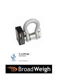
BroadWeigh Shackle Orientation & Identification
The shackle pin and bow are calibrated and load tested
together. It is therefore essential for the accuracy of the system
that the following information is adhered to:
Each pin and bow must be kept as a pair and not interchanged. The
bow is marked with the ID of the pin it is associated with as shown.
The pin must be aligned in the same orientation with the bow as it
was when calibrated. The BroadWeigh shackle is designed to only
fit together in one orientation, the anti-rotational bracket will only
fit around the bow shackle on the side with CE marking. This is the
opposite side to the ID marking.
LOAD
The shackle must be used in conjunction with a bobbin, nut and
retaining clip as shown
The BroadWeigh Shackle is a sensitive measuring device calibrated to ensure accuracy and reliability.
Care must be taken during use, transportation and storage to avoid unnecessary mechanical damage.
To ensure accuracy, load must be applied vertically through the pin and the load must be
centralised with a bobbin.
3
BroadWeigh User Manual www.broadweigh.com
Antenna Orientation
For the maximum range the BroadWeigh Shackle and BroadWeigh Handheld Telemetry Display or USB
Base Station should be orientated as shown.
The sensitivity to the radio transmission will be reduced if the BroadWeigh device is orientated in a
horizontal position.
Guidelines for installation
Radio performance at microwave wavelengths is very dependent upon the operating environment.
When planning installations ensure that:
•
•
•
•
Line-of –sight between BroadWeigh Shackle(s) and BroadWeigh Handheld Telemetry Display or
USB Base Station is maintained.
Objects or structures are kept at least one metre away from antennae wherever possible.
The Broadway Shackle is mounted so that the Mantracourt logo faces the BroadWeigh
Telemetry Display Handheld or USB Base Station.
When moving shackles between environments with large temperature differences it is advised
to allow the temperature of the unit to stabilise for at least 3 hours. After this time a system
zero may be performed if required.
Small increases or reductions in antenna elevation will often improve reception.
BroadWeigh Shackle LED Indicator
The Broadway Shackle is fitted with an LED to provide a visual indication of data transmission from the
acquisition module inside. The LED flashes whenever a data transmission occurs. Modules are preconfigured to provide readings once per second.
Flashing
Constant
Off
data transmitting
paired to T24 Toolkit
unit asleep
BroadWeigh User Manual www.broadweigh.com
4
Basic BroadWeigh Handheld Telemetry Display Operation
Turn the handheld on by pressing and holding the
symbol (on the right) until the display is active.
This will wake the radio and measurement system in the BroadWeigh shackle(s). The displayed value is
in Kg.
The handheld display automatically switches ‘on’ the shackles
as soon as they are in range. The handheld will then display the
shackle with the strongest signal – in most cases the nearest
shackle.
key and the
Select a new shackle to display by pressing the
shackle data tag will be shown briefly before the reading is
displayed. The data tag is (by default) the last 4 characters of
the ID which can be found on the shackle label.
key, the shackle Data Tag currently being measured will be shown.
By pressing and holding the
The currently selected shackle LED will also change from flashing to permanently on.
The handheld can read from an unlimited number of shackles.
The BroadWeigh shackles is pre-set to return to sleep 60 seconds after the handheld is turned off or is
taken out of range.
TIP! – The BroadWeigh Shackle Data Tag can be changed to an easily remembered 4 digit code to reflect its
position within your system. For example ‘A001’. See BroadWeigh Shackle – Advanced settings.
Keys
Press and hold the power key for approximately 2 seconds then release the key.
This will toggle between turning the handheld on and off.
Selects the next module to view.
Pressing and holding will display the currently viewed module Data Tag without
moving to the next module.
Indicators
SIG LOW
BATT LOW
The radio signal from the acquisition module is low. The device is still
functioning but the limit of the range may be near. Communications may start
to deteriorate when this indicator is visible. Until ------ is displayed.
Note: Even with a degraded signal the display value will always be correct.
The batteries in the handheld are low and need to be replaced.
REMOTE ERROR
REMOTE BATT LOW
The BroadWeigh Shackle has an error that the handheld does not recognise.
The batteries of the BroadWeigh Shackle are low and need to be replaced.
Errors
Displayed on handheld LCD.
5
Error 1
The BroadWeigh device has a strain gauge input and is in shunt cal mode. An
external device has placed the acquisition module in Shunt Calibration mode so
rather than display a misleading reading this error is displayed instead.
Modules such as the BroadWeigh Shackle support this error type.
Error 2
Input integrity error. The shackle module has detected a problem with the
input. There may be open or short circuits. Rather than display a misleading
reading this error is displayed instead.
Overload
A user definable value which when exceeded causes this message to be
displayed. The default is 4750 Kg.
BroadWeigh User Manual www.broadweigh.com
BroadWeigh PC Logging Software Quick Start
BroadWeigh Resource CD
The BroadWeigh Resource CD included in the kit comes with two pieces of software:
• T24Log24 – Logging software for up to 24 BroadWeigh Shackles
• T24-Toolkit – for advanced configuration of any BroadWeigh device
The kit also contains a USB base station which is used with the T24Log24 software contained on the
resource software CD. Install this on a PC or Laptop.
Insert the CD. Follow the on-screen prompts.
Once the software is installed connect the USB base station and launch the software.
TIP! – Always check the www.broadweigh.com for the latest software!
Workspace Display Window
The main window displays data for each of up to 24 data channels.
Each data channel display incorporates an ‘LCD’ showing the value, a signal strength indicator, battery
low indicator as well as Zero or Reset button. Data channels can be configured to display different
information.
If communications with a module is lost the display turns red and the value is shown as -------
Pressing the Zero button will immediately tare the display so that the current value shows zero.
Remove a zero by holding the Shift key and clicking the Zero button again or by editing the Workspace.
NOTE: Some data channel displays may show a button with Reset instead of Zero as a caption. These
channels are peak or trough capture channels. See Configure Workspace section.
BroadWeigh User Manual www.broadweigh.com
6
Menu Items
File
Open workspace - Displays a file open dialog window to allow the user to select a previously
saved workspace file. These files have a *.lws extension. Once a workspace is opened it will
overwrite all existing workspace settings.
Save Workspace - Displays a file save dialog window to allow the user to save the current
workspace.
Exit - Close the program.
Edit
Configure Workspace - Opens the configure workspace window
Sleep & Wake
Wake - Wake ALL modules on the same channel.
Sleep - Broadcast a sleep command to ALL modules on the same channel.
Logging
Start Logging - Start logging to a file. This will open a file save, dialog window to allow the
user to select the name and destination of the log file. For log file formats and other
information.
Stop Logging - Stops a previously started log.
View Last Log - This will try and open the last logged file with the application that is
associated with the .csv extension. On most computers this is Microsoft Excel.
About
Opens an about window which gives information on software and driver versions.
7
BroadWeigh User Manual www.broadweigh.com
Configure Workspace Window
Configure the entire display and logging experience. Once configured the workspaces can be saved and
recalled instantly.
Interface - Select either USB or Serial depending on the type of base station connected.
Title - Enter a title for this workspace. This will appear in the title caption of the main window.
COM Port (serial base station only) - Select the COM port that the base station is connected to.
Baudrate (serial base station only) - Select the baudrate that the base station is configured to. This can
have a big effect on the achievable log rates. The user may need to increase the baudrate for fast
acquisition speeds.
Radio Channel - Select the radio channel that matches the acquisition devices. When this window is
closed the base station will be switched over to the selected channel. All shackles are by default set to
channel 1.
Base Station Address (serial base station only) - Select the number address of the connected base
station. This is only useful for cases where multiple base stations are connected. The default of 1
should be suitable in most cases.
Channels - Select the number of display channels displayed on the workspace (including any function
channels such as summed display channels). This can range from 1 to 24.
Log Interval - Set the desired interval between logs in milliseconds.
Notes – Reference notes entered here will be seen in this dialog window.
BroadWeigh User Manual www.broadweigh.com
8
Channel List - This list shows one line for each display channel. To edit the settings click on a line. The
fields below will be updated to show the settings of the selected channel.
Channel - This indicates the display channel number.
Description - Enter a caption to appear on the Workspace and in the column header of the
logged data.
Data Tag- Enter the data tag of the BroadWeigh Shackle to be associated with this channel.
Format - Specify a format for the main window display and also to format the data recorded
into the log file. Just indicate the decimal point position and number of decimal places by using
a period and zero characters. For example: 0.00 or 000.00000
Tare Value - If the user had clicked the zero button on the main window, the value used as the
tare would be shown here. i.e. this value is subtracted from the value reading from the module
to give the value displayed and logged. The user can manually zero this to remove the zero or
enter a manual offset value.
Timeout - Enter a time in seconds, that when exceeded with no incoming signal from this
module, causes any logged data to log the Default value and also to display this channel in solid
red background with -------- shown instead of a value.
Default - If no data is received from this channel, this is the value that will be logged to the
file.
Underload - Enter a net limit below which the channel display will flash red.
Overload - Enter a net limit above which the channel display will flash red.
Function - Here the user can select a function to apply to this channel.
None - No function. Value is displayed as received from the BroadWeigh Shackle.
Sum Previous Channels - This will show the sum of all previous channels. The data tag
entry will be ignored.
Peak Capture - The channel will only display the peak value (max) from the designated
module. The button for this channel has a Reset caption and clicking this will reset the
displayed peak to the current module value.
Trough Capture - The channel will only display the trough value (min) from the
designated module. The button for this channel has a Reset caption and clicking this
will reset the displayed peak to the current module value.
Filter Light - A light filter will be applied to the designated module value. This will
smooth sharp transients.
Filter Medium - A medium filter will be applied to the designated module value. This
will smooth sharp transients but slow down changes.
Filter Heavy - A heavy filter will be applied to the designated module value. This will
smooth out the display at the expense of slow signal changes.
Press the OK button when finished. Please note that the changes will only affect the current session
and will be lost when the user closes the program unless the user chooses to Save Workspace from the
File menu on the main window.
9
BroadWeigh User Manual www.broadweigh.com
Advanced Installation Considerations
E-Stop
Although the BroadWeigh system can be configured to provide data via telemetry 200 times per second, there
are installations that may require 100% connectivity and failsafe systems. The BroadWeigh System is not
suitable for such installations.
Wireless
Where the range of the wireless system exceeds the specified range of the BroadWeigh Shackle or when line of
sight cannot be maintained, the installation should be designed to include the BroadWeigh Active Repeater
module.
The BroadWeigh Active Repeater module will enable the BroadWeigh range of acquisition modules to propagate
wireless signal around obstacles or increase range or coverage. The repeater acts as transparent link between
acquisition modules and the receiver, powered by either a pair of alkaline ‘D’ Cells or an external power supply
(5-18 Volts). The repeater will allow messages to be repeated once - which can effectively double the radio
range. Adding multiple repeaters will not increase the range but can increase overall coverage. However,
adding repeaters will affect the amount of data that can be propagated. Refer to the Active Repeater User
Manual for more information.
BroadWeigh Extended Range USB Base Station
The BroadWeigh Extended Range USB Base Station offers line of sight range of up to 200 metres for all
BroadWeigh acquisition modules. It draws power from the USB bus and therefore no further components are
required to configure and control remote devices from a PC.
The BroadWeigh Extended Range Base Station is supported by not only the BroadWeigh Toolkit but also with a
.dll (Dynamic Link Library) allowing customers using VB (Visual Basic) to develop their own custom software for
their applications.
Interference
The BroadWeigh system uses a proprietary protocol which has been tested with a variety of other 2.4Ghz
devices including Wi-Fi and Bluetooth. Using the T24-Toolkit spectrum analyser will allow users to identify the
source frequency of any potential interference. The system can then be re-configured to operate on another
interference-free channel.
BroadWeigh User Manual www.broadweigh.com
10
T24 Toolkit
Installation
The T24 Toolkit software application is used to configure the devices that make up the BroadWeigh system.
This can be downloaded from www.broadweigh.com or may be shipped with BroadWeigh products.
Install this on a PC or laptop.
Insert the CDRom and follow the on-screen prompts
Setup Base Station Communications
Toolkit items that can be changed by the user are coloured orange.
To change a value click on the relevant orange item. A new dialog window will be displayed allowing the user
to change the value. This may use a slider, text box or list.
Select USB as the interface and select 1 as the Base Station Address.
Click the Home button to communicate with the BroadWeigh base station.
If no communications can be established the toolkit will remain on this page.
11
BroadWeigh User Manual www.broadweigh.com
Home
Once successful communication with the base station is established individual BroadWeigh devices can be
paired to the BroadWeigh USB Base station.
Pairing is achieved by power cycling the device. Pairing removes the need to know the radio settings of the
connecting device and also ensures that it is in a suitable state for configuration with the T24 Toolkit.
Pairing
•
•
•
Procedure
Remove at least one battery from the BroadWeigh Handheld Telemetry Display or BroadWeigh Shackle.
Click the Pair button on the toolkit.
Batteries must be replaced within 10 seconds.
Successful connection will open the Information page.
If the pairing fails try again.
Pressing the Shift key and clicking Pair at the same time will display the Information page for the BroadWeigh
USB Base station.
The paired device will be displayed at the base of the screen. In this example:
‘Connected to Base Station of ID FF9D48 on channel 15’
NOTE: Pairing with the toolkit will not change the radio configuration settings of the connected device.
BroadWeigh User Manual www.broadweigh.com
12
Advanced Module Access
If it is not possible to pair to a module because there is no access to the power supply, use this screen to
connect manually.
Safe Method - The 6 Digit ID of the BroadWeigh device is required.
Full Method – The 4 Digit Data Tag of the BroadWeigh device is required for BroadWeigh Shackles (last 4 digits
of the ID)
13
BroadWeigh User Manual www.broadweigh.com
Data Provider Monitor
BroadWeigh acquisition devices normally operate in low power mode and periodically transmit Data Provider
packets.
This page shows all detected Data Provider packets; which may be useful for checking that a device is
operational.
NOTE: When the toolkit connects to a device to enable configuration it will usually inhibit the transmission of Data Provider packets.
Parameters :
Clear list
Resets the screen and displays only Data Provider packets from active
BroadWeigh Acquisition modules on the selected channel
Wake
Wakes all BroadWeigh acquisition modules within range on the selected
channel
Change Channel
Change the channel of the BroadWeigh USB base station – this will not affect
the channel settings of the acquisition units
View Last Log
Launched the application associated with .CSV files and opens the last logged
file.
Enter a filename in the dialog box to log the received data to a .CSV file in the
following format:
Start Logging
Data Tag, ms Elapsed, Value, Time Stamp
BroadWeigh User Manual www.broadweigh.com
14
Spectrum Analyser
The analyser page is provided as a tool and will not normally be needed unless the user plans to change
channels and needs to find the best channel to select, or to diagnose wireless communication issues.
This page shows the radio signal levels detected across all the channels available to the BroadWeigh range of
devices. Using this tool may help in detecting noisy areas and allow the user to decide on which channels they
may want to use.
The above charts show the traffic from a Wi-Fi network and it can be seen to be operating over channels 6 to 9.
It would be best (though not essential) to avoid using these channels.
15
BroadWeigh User Manual www.broadweigh.com
Advanced Users Only
The following sections of the manual detail the configuration of the individual BroadWeigh modules. An
understanding of these configuration options is not necessary to use the BroadWeigh System. These
configuration options include increasing data rates, sample times, sleep and wake times. Please be aware
altering these settings can result in the system not behaving as expected.
If a specific requirement is not fulfilled by the current configuration please contact a distribution agent for
technical advice.
To access these pages and configure individual BroadWeigh devices it is first necessary to pair a device to
the base station.
Common Configuration Pages for BroadWeigh Devices
Channel
The channel and encryption key for the paired BroadWeigh Shackle or BroadWeigh Handheld Telemetry Display
can be changed from this page.
Note: For BroadWeigh modules other than base stations changing the channel and key will not affect the
module until it has been power cycled
Parameters :
Channel
Encryption Key
Select a channel between 1 and 16. The default is channel 1. Use the
Spectrum Analyser mode to determine a good clean channel to use.
NOTE: Channel 16 is used to negotiate pairing so avoid this channel if possible.
Only devices with identical encryption keys can communicate. Isolate groups
of devices on the same channel or just use the key to ensure the data cannot
be read by somebody else.
BroadWeigh User Manual www.broadweigh.com
16
Channel Advanced
Use this page to change the channel of multiple BroadWeigh shackles and Handheld Telemetry Displays.
• Pair with the BroadWeigh Base station on the Homepage (click Pair whilst holding the ‘Shift’ button).
• Click on the Channel page and set the Channel and Encryption Key
• Click on Advanced to open this page
• Prepare the BroadWeigh module that requires a channel change
• Click on Click Here and follow the on screen prompt to power cycle the BroadWeigh module
Repeater Group
Please refer to the Active Repeater user manual
17
BroadWeigh User Manual www.broadweigh.com
Save and Restore
Use this screen to save the device settings to a file so that they can be later loaded back into the same or
different device.
Parameters:
Save
Restore
Click this button to open a file dialog window to allow the user to select a
filename and location to save the configuration file to.
All configuration information including calibration data will be saved to the
file.
The file extension is .tcf.
Click this button to open a file dialog window to allow the user to select a
filename and location of a previously saved file to load into the connected
device.
All configuration information including calibration data will be overwritten.
The file extension is .tcf.
TIP! – These features are useful if the BroadWeigh device is used in different applications. It may be used to
‘reset’ the shackle to nominal values in a hire situation.
BroadWeigh User Manual www.broadweigh.com
18
BroadWeigh Handheld Telemetry Display - Information
Click on the Home icon and follow the instructions to pair the BroadWeigh device to the Base Station.
Once successfully paired to a BroadWeigh Handheld Telemetry Display this page is displayed.
This page shows information about the connected device.
Parameters:
Name
19
Enter a short description to identify this device in the future (maximum 11 characters).
BroadWeigh User Manual www.broadweigh.com
BroadWeigh Handheld Telemetry Display - Display Format
Use this screen to adjust the display options of a BroadWeigh Handheld Telemetry Display.
Parameters:
Format & Resolution
Define how the values are displayed on the LCD. There are 7 digits available. The user
can define where the decimal point is shown by entering text where a zero indicates a
numeric digit position.
When the data is being displayed the number of defined decimal places may be
overridden as the display will always show the correct number of integer digits.
Example: Set the format to 000.0000 and the value to display is 1000.1234 the display
will show 1000.123
The user can also define the resolution, which is the block size of changes to the
display.
Example: Enter the format as 000.0005 the display will only change in steps of 0.0005
which can be used to mask noisy digits at high resolutions.
Leading Zero
Suppression
This can be turned on or off and will suppress leading zeroes when on.
Example: If the display reads 000.123 with leading zero suppression turned off it will
display 0.123 when turned on.
Overload Limit
Enter a limit here above which Overload will be shown on the display instead of the
actual value.
Enter zero to disable this feature.
Timeout
Enter the timeout in seconds. This sets the time allowed without any data arriving
from the viewed module before all dashes are displayed on the LCD. It should be at
least 3 times the interval between the data being transmitted by the acquisition
module.
BroadWeigh User Manual www.broadweigh.com
20
BroadWeigh Handheld Telemetry Display - Advanced Settings
Use this screen to adjust the advanced settings of the BroadWeigh Handheld Telemetry Display.
Parameters:
List Size
Auto Off Delay
21
Select how many BroadWeigh Shackles the Handheld will scroll through.
Enter a delay in minutes after which the Handheld will power of if no keys pressed.
BroadWeigh User Manual www.broadweigh.com
BroadWeigh Shackle – Information
Click on the Home icon and follow the instructions to pair the BroadWeigh device to the Base Station.
Once successfully paired to a BroadWeigh Shackle this page is displayed.
This page shows the user information about the connected device.
Parameters:
Name
Enter a short description to identify this device in the future (maximum 11 characters).
BroadWeigh User Manual www.broadweigh.com
22
BroadWeigh Shackle - Calibration
These settings are not user definable for the BroadWeigh Product Range.
23
BroadWeigh User Manual www.broadweigh.com
BroadWeigh Shackle – Units
Use this page to select the Output units of the Paired BroadWeigh Shackle.
Parameters:
Output Units
Use the drop down box to select between kg, lbs, tonnes, ton, ton (US) & KN.
Note: If these units are changed ensure the Zero Indication Band is also set correctly.
BroadWeigh User Manual www.broadweigh.com
24
BroadWeigh Shackle - Zero Settings
Use this page to perform system zero and to hide small values of weight (masking) for the paired BroadWeigh
Shackle
Parameters:
Zero Indication Band
This setting enables you to hide small values of weight so that any displays
based on the output from this module will display zero until a certain weight
has been reached. You can enter a value here that represents a ± band around
zero so that if the value to be transmitted is within this band a zero will be
transmitted. Once the weight exceeds this band the real weight will be
transmitted.
For example: A BroadWeigh Shackle with a 5.0kg Zero Indication Band will
only transmit a zero value until 5kg of weight or more is applied.
If you change the module units you will need to adjust the zero indication
band again.
System Zero
If the unloaded shackle is displaying a small weight you can re-zero the output
value by applying a system zero.
Remove the load from the shackle before clicking the ‘Zero Now’ button.
Output Value
This shows the weight value that will be transmitted and shows the effect of
the system zero and the zero indication band.
25
BroadWeigh User Manual www.broadweigh.com
BroadWeigh Shackle - Data Rate
Use this page to select the rate at which data is transmitted from the acquisition module and the quality. By
selecting low power mode and entering some other information the toolkit will also give guides on achievable
battery life.
Note that the battery life calculator assumes a 20°C ambient temperature. To ensure optimum battery life,
only quality alkaline batteries are recommended. Rechargeable batteries are not suitable.
Parameters:
Transmit Interval
Enter the transmission rate in milliseconds. The default is 1000mS for
Broadweigh Shackles.
Longer battery life will be achieved with less frequent transmissions.
Sample Time
This is the length of time in milliseconds that the input is sampled before the
value is transmitted. This can vary between 5 mS and close to the Transmit
Interval. A shorter sample time means that the device is awake for less time
so battery life is increased but at the expense of a reading with less noise free
resolution. Alter this to see the effect on battery life and noise free
resolution.
Low Power Mode
Unless the acquisition module is non battery powered this should be set to
Yes. In-between transmissions the acquisition module will enter sleep mode,
which for some modules such as the strain gauge acquisition module, will have
a massive effect on battery life.
A reason for not using Low Power Mode would be if using the device in a
Master-Slave arrangement with PC for example.
Continued…
BroadWeigh User Manual www.broadweigh.com
26
Battery Type
This is not a parameter of the device but information used by the battery life
guide. Choose from some pre-set battery parameters or choose custom and
select chosen battery capacity. See below. This will also offer to change the
Battery Low Level if the level suitable for the chosen battery is not the level
currently set.
Usable Capacity
This is not a parameter of the device but information used by the battery life
guide. This is the capacity of the battery in Amp Hours and has a profound
effect on battery life calculations. This capacity needs to be calculated from
battery manufacturer’s data sheets to take into account that we can only use
batteries down to 2.1 Volts so in the case of twin AA cells this would be 1.05
Volts.
Generally the usable capacity will not be as high as that advertised by the
battery manufacturer. Temperature and internal resistance of the battery are
not taken into account in the guide.
Sensor Resistance
This is only available for certain acquisition modules. This is not a parameter
of the device but information used by the battery life guide. Enter the
resistance of the connected strain gauge in Ohms.
Usage Per 24 Hour Period
In order to calculate battery life, enter the number of hours per 24-hour
period that the BroadWeigh Shackle will be connected to a BroadWeigh USB
base station or Handheld remote
27
BroadWeigh User Manual www.broadweigh.com
BroadWeigh Shackle – Link Quality Indicator & Battery
Use this page to monitor the voltage of the battery of a BroadWeigh Shackle. The radio signal levels at the base
station and BroadWeigh Shackle can also be monitored. This view gives an LQI (Link Quality Indicator) value
ranging from 0 to 100. As the level drops towards zero communications may become intermittent but still
achievable.
The user can set the level at which the acquisition module reports a low battery.
If the battery voltage is below the Low Battery Level the bar will be coloured orange.
Parameters:
Low Battery Level
Click this item to set the battery low level.
Clicking the Advanced button will give more detailed information on the RSSI and CV levels of the received
radio packets.
BroadWeigh User Manual www.broadweigh.com
28
BroadWeigh Shackle - Link Quality Indicator & Battery Advanced
LQI (Link Quality Indicator) value ranging from 0 to 100. As the level drops towards zero communications may
become intermittent but still achievable.
RSSI is effectively the received dB level which will range from about -30 which is a good signal to -90 which is a
weak signal.
CV is the correlation value and indicates how well the signal can be decoded. This ranges from 55 which is a
poor quality signal and 110 which is an excellent signal.
29
BroadWeigh User Manual www.broadweigh.com
BroadWeigh Shackle – Advanced Settings
It should not normally be necessary to change these settings.
Parameters:
Sleep Delay
Enter a delay in seconds after which the BroadWeigh Device will return to
deep sleep if no Keep Awake message is heard from the BroadWeigh Handheld
Telemetry Display or USB Base Station. The default is 60 seconds.
Note: If a value of 0 is used the shackle will not enter into low power state
and battery life will be compromised.
Data Tag
The data transmitted by the BroadWeigh Shackle is marked with a Data Tag.
By default this is set to the last 4 characters of the device ID. The BroadWeigh
Shackle Data Tag can be changed to an easily remembered 4 digit code to
reflect its position within your system. For example ‘1PAL’ (unit 1 PA left).
BroadWeigh User Manual www.broadweigh.com
30
Specifications
General Radio
Min
Typical
Max
Units
License
License Exempt
Modulation method
MS (QPSK)
Radio type
Transceiver (2 way)
Data rate
250
K bits/sec
Radio Frequency
2.4000
2.4835
GHz
Power
1
mw
Range to T24-BSu base station
100 (330)
Metres (feet) *
Range to t24-BSue base station or
200 (650)
Metres (feet) *
handheld
Channels (DSSS)
16
* Maximum range achieved in open field site at a height of 3 metres above ground using BWSHK and BW-HR.
BW-HR BroadWeigh Handheld Telemetry Display
Power Supply
Estimated Battery life 2 X AA Duracell
batteries:
Standby mode (Powered off)
Continuous operation
Min
Environmental
IP rating
Operating temperature range
Storage temperature*
Humidity
* Excludes Batteries.
Min
Typical
Max
1.5
40
Typical
IP65
-20
-40
0
Physical
Hand Held Dimensions
Units
Years
Hours
Max
Units
+50
+85
95
C
C
%RH
90 x 152 x 34mm
BW-S475/BW-S325 BroadWeigh Shackle
Measurement
Range
Accuracy
Min
Power Supply
Estimated Battery life 2 X AA Duracell
batteries (1 update per second):
Asleep
Continuous operation
8 Hours Usage Per Day
2 Hours Usage Per Day
Min
Environmental
IP rating
Operating temperature range
Storage temperature*
Humidity
* Excludes Batteries.
Min
31
BroadWeigh User Manual www.broadweigh.com
Typical
Max
Units
4750/3250
kg
Typically ±1% of load or ±25kg whichever is greater
Typical
Max
5+
3
8
2.5
-20
-40
0
Typical
IP65
Units
Years
Months
Months
Years
Max
Units
+50
+85
95
°C
°C
%RH
BW-S475 BroadWeigh Shackle 4.75T dimensions
BW-S325 BroadWeigh Shackle 3.25T dimensions
BroadWeigh User Manual www.broadweigh.com
32
Approvals
CE
Complies with EMC directive. 2004/108/EC
The Radio Equipment and Telecommunications Terminal Equipment (R&TTE) Directive,
1999/5/EC,
European Community, Switzerland, Norway, Iceland, and Liechtenstein
English:
This equipment is in compliance with the essential requirements and other
relevant provisions of Directive 1999/5/EC.
Deutsch:
Dieses Gerät entspricht den grundlegenden Anforderungen und den weiteren
entsprecheneden Vorgaben der Richtlinie 1999/5/EU.
Dansk:
Dette udstyr er i overensstemmelse med de væsentlige krav og andre relevante
bestemmelser i Directiv 1999/5/EF.
Español:
Este equipo cumple con los requisitos esenciales asi como con otras
disposiciones de la Directive 1999/5/EC.
Français:
Cet appareil est conforme aux exigencies essentialles et aux autres dispositions
pertinantes de la Directive 1999/5/EC.
Íslenska:
Þessi búnaður samrýmist lögboðnum kröfum og öðrum ákvæðum tilskipunar
1999/5/ESB.
Italiano:
Questo apparato é conforme ai requisiti essenziali ed agli altri principi sanciti
dalla Direttiva 1999/5/EC.
Nederlands: Deze apparatuur voldoet aan de belangrijkste eisen en andere voorzieningen
van richtlijn 1999/5/EC.
Norsk:
Dette utstyret er i samsvar med de grunnleggende krav og andre relevante
bestemmelser i EU-directiv 1999/5/EC.
Português:
Este equipamento satisfaz os requisitos essenciais e outras provisões da
Directiva 1999/5/EC.
Suomalainen: Tämä laite täyttää direktiivin 1999/5/EY oleelliset vaatimukset ja on siinä
asetettujen muidenkin ehtojen mukainen.
Svenska:
Denna utrustning är i överensstämmelse med de väsentliga kraven och andra
relevanta bestämmelser i Direktiv 1999/5/EC.
This equipment is in compliance with the essential requirements and other relevant provisions of Directive
1999/5/EC.
FCC
Family: RAD24
Models: i and e for internal and external antenna variants. For antenna T24-ANTA and T24-ANTB
FCC ID:VHARAD24
This device complies with Part 15c of the FCC Rules. Operation is subject to the following two conditions: (1) this
device may not cause harmful interference, and (2) this device must accept any interference received, including
interference that may cause undesired operation.
CAUTION: If the device is changed or modified without permission from Mantracourt Electronics Ltd, the user
may void his or her authority to operate the equipment.
33
BroadWeigh User Manual www.broadweigh.com
Industry Canada
Models: i and e for internal and external antenna variants. For antenna T24-ANTA and T24-ANTB
IC:7224A-RAD24
This apparatus complies with RSS-210 - Low-power Licence-exempt Radiocommunication Devices (All Frequency
Bands): Category I Equipment RSS.
OEM / Reseller Marking and Documentation Requirements
FCC
The Original Equipment Manufacturer (OEM) must ensure that FCC labelling requirements are met. This
includes a clearly visible label on the outside of the final product enclosure that displays the contents as
shown:
Contains FCC ID:VHARAD24
This device complies with Part 15 of the FCC Rules. Operation is subject to the following two conditions:
(1) this device may not cause harmful interference and
(2) this device must accept any interference received, including interference that may cause undesired operation.
The acquisition modules have been tested with T24-ANTA and T24-ANTB. When integrated in OEM products,
fixed antennas require installation preventing end-users from replacing them with non-approved antennas.
Antennas other than T24-ANTA and T24-ANTB must be tested to comply with FCC Section 15.203 (unique
antenna connectors) and Section 15.247 (emissions).
Acquisition modules have been certified by the FCC for use with other products without any further
certification (as per FCC section 2.1091). Changes or modifications not expressly approved by Mantracourt
could void the user’s authority to operate the equipment.
In order to fulfil the certification requirements, the OEM must comply with FCC regulations:
1. The system integrator must ensure that the text on the external label provided with this device is placed on
the outside of the final product.
2. The acquisition modules with external antennas may be used only with Approved Antennas that have been
tested by mantracourt.
IC
Labelling requirements for Industry Canada are similar to those of the FCC. A clearly visible label on the
outside of the final product enclosure must display the following text:
Contains Model RAD24 Radio (2.4 GHz), IC:7224A-RAD24
Integrator is responsible for its product to comply with RSS-210 - Low-power Licence-exempt
Radiocommunication Devices (All Frequency Bands): Category I Equipment RSS.
CE
The T24 series has been certified for several European countries.
If the acquisition module is incorporated into a product, the manufacturer must ensure compliance of the final
product to the European harmonized EMC and low-voltage/safety standards. A Declaration of Conformity must
be issued for each of these standards and kept on file as described in Annex II of the R&TTE Directive.
Furthermore, the manufacturer must maintain a copy of the T24 device user manual documentation and ensure
the final product does not exceed the specified power ratings, antenna specifications, and/or installation
requirements as specified in the user manual. If any of these specifications are exceeded in the final product, a
submission must be made to a notified body for compliance testing to all required standards.
OEM Labelling Requirements
The ‘CE’ marking must be affixed to a visible location on the OEM product.
BroadWeigh User Manual www.broadweigh.com
34
The CE mark shall consist of the initials “CE” taking the following form:
If the CE marking is reduced or enlarged, the proportions given in the above graduated drawing must be
respected.
The CE marking must have a height of at least 5mm except where this is not possible on account of the
nature of the apparatus.
The CE marking must be affixed visibly, legibly, and indelibly.
35
BroadWeigh User Manual www.broadweigh.com
Declaration Of Conformity
We, Mantracourt Electronics Limited
The Drive
Farringdon
Exeter
Devon EX5 2JB
declare under our sole responsibility that our products in the T24 Radio Telemetry Product Range to which
this declaration relates are in conformity with the appropriate standard EN 300 328 following the provisions of
the Radio and Telecommunications Terminal Equipment Directive 1999/5/EC, FCC CFR Title 47 part 15c BS EN
61000-4-2 and BS EN 61000-4-3 following the provisions of the EMC Directive 2004/108/EC and Low Voltage
Directive 2006/95/EC.
December 2007
Brett James
Development Manager
Mantracourt Electronics Limited.
BroadWeigh User Manual www.broadweigh.com
FCC ID:VHARAD24
36
Worldwide Regional Approvals
Region
Europe
USA
Canada
Australia
China
Japan
Product Conforms To
CE
FCC
IC
To Be Determined
To Be Determined
To Be Determined
Important Note
Mantracourt does not list the entire set of standards that must be met for each country. Mantracourt customers
assume full responsibility for learning and meeting the required guidelines for each country in their distribution
market. For more information relating to European compliance of an OEM product incorporating the T24 range
of modules, contact Mantracourt, or refer to the following web site: www.ero.dk
37
BroadWeigh User Manual www.broadweigh.com
Warranty
All Telemetry products from Mantracourt Electronics Ltd., ('Mantracourt') are warranted against defective
material and workmanship for a period of (1) one year from the date of dispatch.
If the 'Mantracourt' product you purchase appears to have a defect in material or workmanship or fails during
normal use within the period, please contact your Distributor, who will assist you in resolving the problem. If it
is necessary to return the product to 'Mantracourt' please include a note stating name, company, address,
phone number and a detailed description of the problem. Also, please indicate if it is a warranty repair.
The sender is responsible for shipping charges, freight insurance and proper packaging to prevent breakage in
transit.
'Mantracourt' warranty does not apply to defects resulting from action of the buyer such as mishandling,
improper interfacing, operation outside of design limits, improper repair or unauthorised modification.
No other warranties are expressed or implied. 'Mantracourt' specifically disclaims any implied warranties of
merchantability or fitness for a specific purpose. The remedies outlined above are the buyer’s only remedies.
'Mantracourt' will not be liable for direct, indirect, special, incidental or consequential damages whether based
on the contract, tort or other legal theory.
Any corrective maintenance required after the warranty period should be performed by 'Mantracourt' approved
personnel only.
In the interests of continued product development, Mantracourt Electronics Limited reserves the right to alter product specifications without prior notice.
Code No. 517-927
BroadWeigh User Manual www.broadweigh.com
Issue 2.2
11.04.14
38