1
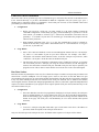
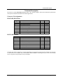
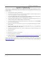
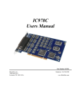
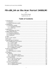
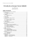
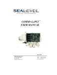
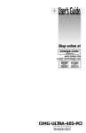
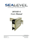
SeaLINK+8.Ultra
Users Manual
Part # 4803
Sealevel Systems, Inc.
155 Technology Place
Liberty, SC 29657 USA
Telephone: 864.843.4343
Fax: 864.843.3067
www.sealevel.com
Contents
INTRODUCTION ..................................................................................................................... 1
OVERVIEW .........................................................................................................................................1
WHAT’S INCLUDED ............................................................................................................................1
CARD SETUP ......................................................................................................................... 2
ELECTRICAL INTERFACE SELECTION ..................................................................................................2
RS-485 ENABLE MODES ....................................................................................................................2
SOFTWARE INSTALLATION ................................................................................................... 3
WINDOWS 98/ME/NT/2000/XP.........................................................................................................3
LINUX ................................................................................................................................................3
LOCATING THE DEVICE AND ASSIGNING AN IP ADDRESS...................................................................3
DEVICE CONFIGURATION WITH WINDOWS .........................................................................................3
DEVICE CONFIGURATION WITH LINUX ...............................................................................................4
WEB CONFIGURATION .......................................................................................................................4
PORT DEFAULTS.................................................................................................................................4
CUSTOM BAUD RATES .......................................................................................................................4
RESETTING TO FACTORY DEFAULTS ..................................................................................................4
WINDOWS DEVICE DRIVER CONFIGURATION .....................................................................................5
LINUX DEVICE DRIVER INSTALLATION ..............................................................................................6
RAW DATA SOCKETS .........................................................................................................................6
TECHNICAL DESCRIPTION.................................................................................................... 7
CONNECTOR PIN ASSIGNMENTS .........................................................................................................7
RS-422/485 (DB 9 Male) ...............................................................................................................7
RS-232 (DB-9 Male) ......................................................................................................................7
SPECIFICATIONS ................................................................................................................... 8
ENVIRONMENTAL SPECIFICATIONS ....................................................................................................8
MANUFACTURING ..............................................................................................................................8
APPENDIX A - TROUBLESHOOTING ...................................................................................... 9
APPENDIX B - HOW TO GET ASSISTANCE ......................................................................... 10
APPENDIX C - ELECTRICAL INTERFACE ............................................................................ 11
RS-232 ............................................................................................................................................11
RS-422 ............................................................................................................................................11
RS-485 ............................................................................................................................................11
APPENDIX D - ASYNCHRONOUS COMMUNICATIONS ......................................................... 12
APPENDIX E – BACK PANEL ............................................................................................... 13
APPENDIX F - COMPLIANCE NOTICES ............................................................................... 14
FEDERAL COMMUNICATIONS COMMISSION STATEMENT ..................................................................14
EMC DIRECTIVE STATEMENT ..........................................................................................................14
WARRANTY ......................................................................................................................... 15
© Revision May 26, 2004
Sealevel Systems, Incorporated. All rights reserved.
Introduction
Introduction
Overview
The Sealevel SEALINK+8.ULTRA (Part number 4803) is an eight channel RS-232/422/485 Ethernet based serial
I/O adapter supporting data rates up to 230.4 K bps.
The RS-232 compatibility allows for connection to devices utilizing the RS-232 electrical interface, such as
modems, data-entry terminals, and plotters.
RS-422 provides excellent communications for long distance device connections up to 4000ft., where noise
immunity and high data integrity are essential.
RS-485 is optimized for ‘Multi-Drop’ or ‘Party-line’ operations selecting data from multiple peripherals (as many as
31 devices can be connected on an RS-485 bus).
What’s Included
The SEALINK+8.ULTRA is shipped with the following items. If any of these items is missing or damaged, contact
the supplier.
•
•
•
•
•
SEALINK+8.ULTRA Ethernet Terminal Adapter
Sealevel Software
5 volt power adapter, Sealevel Systems part number TR101
Ethernet cable, straight through (blue)
Ethernet cable, cross over (yellow)
Sealevel Systems SeaLink+8.Ultra
Page 1
Card Setup
Card Setup
Electrical Interface Selection
Each port on the SEALINK+8.ULTRA has the ability to be used in RS-422/485. This is selectable using the
software setup utility and correctly configuring DIP-switches S1-S4.
RS-422/485
1 2 3 4 5 6 7 8
EN
T
PD
PU
EN
T
PD
PU
ON
OFF
1 2 3 4 5 6 7 8
1 2 3 4 5 6 7 8
RS-232
ON
OFF
ON
OFF
EN
T
PD
PU
EN
T
PD
PU
EN
T
PD
PU
EN
T
PD
PU
RS-422/485 No termination
RS-485 Enable Modes
RS-485 is ideal for multi-drop or network environments. RS-485 requires a tri-state driver that will allow the
electrical presence of the driver to be removed from the line. The driver is in a tri-state or high impedance condition
when this occurs. One of the unique features of the SEALINK+8.ULTRA is the ability to be RS-485 compatible
without the need for special software or drivers. This ability means that the user can effectively use the
SEALINK+8.ULTRA in an RS-485 application with the standard Sealevel Software supplied drivers.
Typically, each end of the RS-485 bus must have a line-terminating resistor (RS-422 terminates the receive end
only). A 120-ohm resistor (silk-screen ‘T’) is across each RS-422/485 input in addition to a 1K-ohm pull-up (silkscreen ‘PU’) and a 1K-ohm pull down (silk-screen ‘PD’) combination that biases the receiver inputs. Only the ends
of an RS-485 network should have the 120-Ohm terminating resistor. The presence of the 120-Ohm termination
resistor across the input data pins (RX+/RX-) as well as the pull-up and pull-down resistors may be removed or
inserted with DIP-switches S1-S4. To add the termination/bias resistors select the ‘On’ position, to remove it select
the ‘Off’ position.
Sealevel Systems SeaLink+8.Ultra
Page 2
Software Installation
Software Installation
Unlike most other adapters, the SeaLINK+8.Ultra may physically be connected before the software has been
installed. To completely install the adapter attach a 10/100 Base T Ethernet cable to the appropriate connector, make
the connections for your serial port and connect the provided AC adapter or provide 5 VDC at 1A.
Windows 98/ME/NT/2000/XP
1.
Start Windows.
2.
Insert the Sealevel Systems CD in to your CD drive.
3.
If ‘Auto-Start’ is enabled for this drive the software will automatically launch. Otherwise, point your
browser to the ‘Index.htm’ on the root directory of the CD.
4.
Select ‘Install Software’.
5.
Select the Part Number for your adapter from the listing.
6.
Select ‘Windows 98/ME/2000/XP’. The setup file will automatically detect the operating environment and
install the proper components. Next (depending on the OS version) select the ‘Run this program from its
current location’ or ‘Open’ option. Follow the information presented on the screens that follow.
7.
A screen may appear with the declaration: “The publisher cannot be determined due to the problems
below: Authenticode signature not found.” Please select the ‘Yes’ button and proceed with the installation.
This declaration simply means that the Operating System is not aware of the driver being loaded. It will not
cause any harm to your system.
8.
During setup the user may specify installation directories and other preferred configurations. This program
also adds entries to the system registry that are necessary for specifying the operating parameters for each
driver. An uninstall option is also available to remove all registry/INI file entries from the system.
Linux
If you have downloaded the source code in .tar.gz format, type "tar xzvf filename.tar.gz" to extract the files and
refer to the INSTALL file in the extracted directory. If you have downloaded an RPM file compatible with your
system, type "rpm -i filename.rpm" to install the software.
Locating the Device and Assigning an IP Address
Before the SeaLINK device can be used, it must be assigned an IP address valid to your network. When first
powered up, the device will attempt to automatically find an IP address using DHCP. If the device is linked but
cannot locate a DHCP server, the link LED on the box will flash, indicating that the device does not have valid
network setting. In that case, you will need to assign it a static address using the configuration utility provided. The
configuration utility (Start\Programs\SeaLINK\SeaLINKConfig.exe) is also useful for locating devices to determine
the IP address. The method depends on your operating system, so see the appropriate section below.
Device Configuration with Windows
Windows device configuration is performed through the “SeaLINKConfig.exe” (Start\Programs\SeaLINK\) utility
provided with the software installation. When started, the utility will display all devices on the local network (the
utility cannot see devices on the other side of a router). If your device is not listed, verify that it is connected to the
network (see the section Troubleshooting). To assign static IP addresses, select your device in the list, then uncheck
the box that says “Enable DHCP” and change the “IP”, “Gateway”, and “Network Mask” fields to values valid on
your network. Then click “Apply Changes”. The device will reboot and temporarily disappear from view, so you
may need to click “Search Again” to relocate the device.
Sealevel Systems SeaLink+8.Ultra
Page 3
Software Installation
Device Configuration with Linux
Linux device configuration is performed through the “SeaLINKConfig” console utility provided with the software
installation. Once the software has been installed correctly, type “/usr/sbin/sealinkcfg” to launch the program. You
should see a list of all devices on the local network (the utility cannot see devices on the other side of a router). If
your device is not listed, verify that it is connected to the network (see the section Troubleshooting). To assign a
static IP address, type ‘c’ (for configure) followed by the number of your hub in the displayed list (probably “c 1”).
Hit return, and answer ‘n’ when asked if the device should use DHCP. Then enter “IP”, “Gateway” and “Network
Mask” settings valid on your network. The device will reboot and temporarily disappear from view, so you may
need to type ‘r’ to refresh the device list.
Web Configuration
Once the device has been assigned an IP address reachable from your computer, you can configure it through the
onboard web server. Open a web browser such as Internet Explorer or Netscape and type “http://x.x.x.x” into the
URL field, where “x.x.x.x” is the device’s IP address. The web interface provides a summary page that lists various
details about the device, a port settings page that allows you to configure aspects of each serial port, and an
administration page that lets you change the device’s network and password settings.
Port Defaults
The Port Settings page allows you to set defaults for the serial port. If you are using a virtual serial port protocol
such as SeaLINK Software, programs may change these settings dynamically after opening the ports. If you want
programs to always use the defaults you set, check the box labeled "Always use defaults". This can be useful
especially when specifying a custom baud rate that is not available from your operating system (see Custom Baud
Rates).
Custom Baud Rates
From the Port Settings Page, you can enter a baud rate of any value from 1 to 230400. While it may not be possible
to hit the exact desired baud rate, the UART will attempt to set it as closely as possible and will be within an
acceptable 2% range. After you click Submit, the page will refresh and display the baud rate actually being used.
Resetting to Factory Defaults
If you have forgotten your password or otherwise wish to reset the device to the factory defaults, manually browse
to "http://x.x.x.x/debug.htm" (where x.x.x.x is the device's IP address) and click the button marked "Reset to Factory
Defaults". You will be prompted for a username and password. For the username, enter "debug". In the password
field, type the MAC address of the unit, located either on the summary page or on the label on the device. The MAC
address should be entered without formatting such as dashes or spaces.
Sealevel Systems SeaLink+8.Ultra
Page 4
Software Installation
Windows Device Driver Configuration
SeaLINK is a general-purpose redirector client from Sealevel Systems, Inc. that lets Windows-based PC
applications use shared serial lines on serial servers. SeaLINK supports up to 16 redirected COM ports.
With SeaLINK, you can configure Windows applications to communicate with COM ports on a remote serial server
as if they were local to the PC
Users with a basic understanding of Windows can follow the steps below to be up and running in minutes. More
information is available in the full User’s Guide and on the Sealevel Systems, Inc. website.
1.
Confirm the following:
•
2.
You are using an Intel-compatible PC running Windows 2000, Windows NT 4.0 SP5, Windows ME,
Windows 98 or Windows XP.
Install SeaLINK on your PC:
•
Log in as a user with administration privileges. (It is not necessary to be an admin to use SeaLINK.)
•
Quit all Windows programs that use COM ports.
•
Run the SeaLINKConfig program and note your IP address. SeaLINKConfig will find all of the SeaLINK
servers currently installed on the same network segment (Broadcast Domain) as the machine you are
executing it from.
3.
Create the SeaLINK COM ports:
•
After the installer runs, the Select Ports Window appears. Check one or more new COM ports for
SeaLINK to create and click OK.
Note: The list of COM ports will not include those already in use by Windows on this PC.
4.
Configure and verify SeaLINK COM ports: Do not enter any values in the User Name or Password
field. These fields are not valid for this version of SeaLINK.
•
The main SeaLINK Window should now be open. If not, right click on the SeaLINK icon in the System
Tray and choose Configure. Then enter the serial server’s IP Address and Port Number in the boxes
provided for each COM port.
Note: The SeaLINK Serial Server will place the port at 4680
•
Click the Configuration Wizard button in the Main Window and then click Start. This important step will
confirm that each new port just created can communicate with the serial server at the specified IP address
and port number. Once the Status returns a series of green checkmarks indicating a working configuration
click the Use Settings button and proceed to the last step of setting up your applications.
•
Use WinSSD to verify that the COM ports a re configured correctly and fully functional.
•
See the Installation chapter in the User’s Guide if you need more information.
5.
Reconfigure your applications to use remote devices or SeaLINK COM ports:
•
Change your application settings to use a previously installed SeaLINK COM port.
Your application can now be used over a Windows TCP/IP network.
Sealevel Systems SeaLink+8.Ultra
Page 5
Software Installation
Linux Device Driver Installation
The source code is in .tar.gz format, type "tar xzvf filename.tar.gz" to extract the files and refer to the INSTALL file
in the extracted directory. If you have downloaded an RPM file compatible with your system, type "rpm -i
filename.rpm" to install the software. To implement a virtual serial port in Linux, use the SeaLINK virtual serial
port module, provided in the software installation.
1.
2.
Configuration
•
Before you can access a serial port, you must “install” it to the client computer. Launch the
“SeaLINK Configuration” console utility by typing “/usr/sbin/sealinkcfg”. If your device is on the
local network, you should see it listed. Type ‘i’ followed by the number of the hub in the list
(probably “i 1”) to install it. If your device is not listed, type 'n' and follow the prompts to tell the
software about your device.
•
When finished configuring ports, type ‘q’ to quit. The SeaLINK driver must be restarted (or
started for the first time), so type either “/sbin/sealink restart” or “/sbin/sealink start”. If one gives
you an error, try the other one.
Usage Details
•
Once a device has been installed, it can be accessed through the character devices “/dev/ttySL[0n]”, where ‘n’ is the number of ports on your device minus one. For example, “echo hello >
/dev/ttySL0” will send the ASCII characters “hello” to the first serial port on your device, while
“echo hello > /dev/ttySL2” will do the same for the third serial port.
•
The /dev/ttySL devices are designed to communicate with a virtualized a serial port, so programs
can access them just like a /dev/ttyS port using the termios functions (see the man page for
termios). Note that unlike a normal serial port, SeaLINK serial ports can only be opened by one
program at a time. This is done to ensure that the correct client receives the correct data/signals.
Raw Data Sockets
Raw Data Sockets are probably the easiest way for a software developer to control a serial port, but provide the least
control from a software standpoint. You can simply open a socket to the device on the Raw Data TCP port
corresponding to the serial port you want and stream data back and forth. The data will not be inspected or modified
in any way. This method provides the least control because serial port functions such as baud rate and modem
control signals cannot be monitored or changed programmatically. However, Raw Data is platform-independent and
requires no software installation. If your purposes do not require dynamic serial port control, Raw Data may be the
most efficient choice for you.
1.
Configuration
•
2.
Since Raw Data does not allow for programmatic changing of serial port controls, the serial ports
must be configured before use via the onboard web server (see the section Web Configuration).
From the Port Settings page, configure the ports to the desired settings and click Submit at the
bottom of the page. The serial ports will automatically be set to these defaults when opened
Selection).
Usage Details
•
To access a serial port using Raw Data mode, open a TCP socket to the device’s IP address on
port 4760, which corresponds to the serial port on the device.
Only one client can open each serial port at a time. All further socket requests to a TCP port will be denied.
Sealevel Systems SeaLink+8.Ultra
Page 6
Technical Description
Technical Description
The Sealevel Systems SEALINK+4.Ultra provides a PCI interface adapter with 8 RS-232/422/485 asynchronous
serial ports for industrial automation and control applications.
Connector Pin Assignments
RS-422/485 (DB 9 Male)
Signal
GND
TX +
TXRTS+
RTSRX+
RXCTS+
CTS-
Name
Ground
Transmit Data Positive
Transmit Data Negative
Request To Send Positive
Request To Send Negative
Receive Data Positive
Receive Data Negative
Clear To Send Positive
Clear To Send Negative
Pin #
5
4
3
6
7
1
2
9
8
Name
Ground
Transmit Data
Request To Send
Data Terminal Ready
Receive Data
Clear To Send
Data Set Ready
Data Carrier Detect
Ring Indicator
Pin #
5
3
7
4
2
8
6
1
9
Mode
Output
Output
Output
Output
Input
Input
Input
Input
RS-232 (DB-9 Male)
Signal
GND
TD
RTS
DTR
RD
CTS
DSR
DCD
RI
Mode
Output
Output
Output
Input
Input
Input
Input
Input
Technical Note: Please terminate any control signals that are not going to be used. The most common way to do this
is connect RTS to CTS and RI. Also, connect DCD to DTR and DSR. Terminating these pins, if not used, will help
ensure you get the best performance from your adapter.
Sealevel Systems SeaLink+8.Ultra
Page 7
Specifications
Specifications
Environmental Specifications
Specification
Temperature
Range
Humidity Range
Operating
0º to 70º C
(32º to 158º F)
10 to 90% R.H.
Non-Condensing
Storage
-50º to 105º C
(-58º to 221º F)
10 to 90% R.H.
Non-Condensing
Manufacturing
All Sealevel Systems Printed Circuit boards are built to UL 94V0 rating and are 100% electrically tested. These
printed circuit boards are solder mask over bare copper or solder mask over tin nickel.
Sealevel Systems SeaLink+8.Ultra
Page 8
Appendix A - Troubleshooting
Appendix A - Troubleshooting
Sealevel Software is supplied with the Sealevel Systems adapter and will be used in the troubleshooting procedures.
Using this software and following these simple steps can eliminate most common problems, without the need to call
Technical Support.
1.
Verify that the Power LED is lit and remains on.
2.
Verify that the Link LED remains on to determine that the 10/100 Base-T connections and the polarity are
correct. If the Link LED is lit, you have a valid Link condition.
3.
Verify that the Ethernet LED remains on to determine that the 10/100 Base-T connections and the polarity
are correct. If the Ethernet LED is lit, you have a working Ethernet connection
4.
Verify that the correct cable is being used (i.e. ‘Straight-thru’ for switch/hub connection and ‘cross over’
for direct connection to NIC), and that all cables are connected securely.
5.
Verify that the Ethernet Hub, Switch, and any other network devices between the server and the SeaLINK
device is powered up and operating.
6.
Ensure that the Serial Server and Client are in the same sub-net (Broadcast Domain) and not behind a
router or bridge.
7.
Ensure that the IP address in the Client is the same as the IP address of the Server. If using DHCP this
address is subject to change after a Server reboot.
8.
To isolate the unit from the network, use a ‘crossover’ Ethernet cable to connect the unit directly to the
NIC card in the server.
9.
Reboot the server.
10. Ensure that server software is correctly loaded.
11. Remove and reload the server software.
12. Update the firmware at ftp://ftp.sealevel.com/pub/SOFTWARE/SEALINK/Firmware/CURRENT/ This
link will provide the file and directions for updating your firmware.
Always use the Sealevel Systems diagnostic software when troubleshooting a problem. This will eliminate any
software issues from the equation. If you are unable to resolve the problem, contact Technical Support at:
mailto:[email protected] .
Sealevel Systems SeaLink+8.Ultra
Page 9
Appendix B – How to Get Assistance
Appendix B - How To Get Assistance
Please refer to Troubleshooting Guide prior to calling Technical Support.
1.
Begin by reading through the Trouble Shooting Guide in Appendix A. If assistance is still needed
please see below.
2.
When calling for technical assistance, please have your user manual and current adapter settings. If
possible, please have the adapter installed in a computer ready to run diagnostics.
3.
Sealevel Systems provides an FAQ section on its web site. Please refer to this to answer many
common questions. This section can be found at http://www.sealevel.com/faq.asp.
4.
Sealevel Systems maintains a web page on the Internet. Our home page address is
http://www.sealevel.com. The latest software updates, and newest manuals are available via our web
site.
5.
Technical support is available Monday to Friday from 8:00 a.m. to 5:00 p.m. eastern time. Technical
support can be reached at (864) 843-4343.
Return Authorization Must Be Obtained From Sealevel Systems Before Returned Merchandise Will Be
Accepted. Authorization Can Be Obtained By Calling Sealevel Systems And Requesting A Return
Merchandise Authorization (RMA) Number.
Sealevel Systems SeaLink+8.Ultra
Page 10
Appendix C – Electrical Interface
Appendix C - Electrical Interface
RS-232
Quite possibly the most widely used communication standard is RS-232. This implementation has been defined and
revised several times and is often referred to as RS-232-C/D/E or EIA/TIA-232-C/D/E. It is defined as “Interface
between Data Terminal Equipment and Data Circuit- Terminating Equipment Employing Serial Binary Data
Interchange”. The mechanical implementation of RS-232 is on a 25-pin D sub connector. The IBM PC computer
defined the RS-232 port on a 9 pin D sub connector and subsequently the EIA/TIA approved this implementation as
the EIA/TIA-574 standard. This standard has defined as the “9-Position Non-Synchronous Interface between Data
Terminal Equipment and Data Circuit-Terminating Equipment Employing Serial Binary Data Interchange”. Both
implementations are in wide spread use and will be referred to as RS-232 in this document. RS-232 is capable of
operating at data rates up to 20K bps / 50 ft. The absolute maximum data rate may vary due to line conditions and
cable lengths. RS-232 often operates at 38.4K bps over very short distances. The voltage levels defined by RS-232
range from -12 to +12 volts. RS-232 is a single ended or unbalanced interface, meaning that a single electrical
signal is compared to a common signal (ground) to determine binary logic states. A voltage of +12 volts (usually +3
to +10 volts) represents a binary 0 (space) and -12 volts (-3 to -10 volts) denote a binary 1 (mark). The RS-232 and
the EIA/TIA-574 specification define two types of interface circuits Data Terminal Equipment (DTE) and Data
Circuit-Terminating Equipment (DCE). The Sealevel Systems Adapter is a DTE interface.
RS-422
The RS-422 specification defines the electrical characteristics of balanced voltage digital interface circuits. RS-422
is a differential interface that defines voltage levels and driver/receiver electrical specifications. On a differential
interface, logic levels are defined by the difference in voltage between a pair of outputs or inputs. In contrast, a
single ended interface, for example RS-232, defines the logic levels as the difference in voltage between a single
signal and a common ground connection. Differential interfaces are typically more immune to noise or voltage
spikes that may occur on the communication lines. Differential interfaces also have greater drive capabilities that
allow for longer cable lengths. RS-422 is rated up to 10 Megabits per second and can have cabling 4000 feet long.
RS-422 also defines driver and receiver electrical characteristics that will allow 1 driver and up to 32 receivers on
the line at once. RS-422 signal levels range from 0 to +5 volts. RS-422 does not define a physical connector.
RS-485
RS-485 is backwardly compatible with RS-422; however, it is optimized for party line or multi-drop applications.
The output of the RS-422/485 driver is capable of being Active (enabled) or Tri-State (disabled). This capability
allows multiple ports to be connected in a multi-drop bus and selectively polled. RS-485 allows cable lengths up to
4000 feet and data rates up to 10 Megabits per second. The signal levels for RS-485 are the same as those defined
by RS-422. RS-485 has electrical characteristics that allow for 32 drivers and 32 receivers to be connected to one
line. This interface is ideal for multi-drop or network environments. RS-485 tri-state driver (not dual-state) will
allow the electrical presence of the driver to be removed from the line. Only one driver may be active at a time and
the other driver(s) must be tri-stated. RS-485 can be cabled in two ways, two wire and four wire mode. Two-wire
mode does not allow for full duplex communication, and requires that data be transferred in only one direction at a
time. For half-duplex operation, the two transmit pins should be connected to the two receive pins (Tx+ to Rx+ and
Tx- to Rx-). Four wire mode allows full duplex data transfers. RS-485 does not define a connector pin-out or a set
of modem control signals. RS-485 does not define a physical connector.
Sealevel Systems SeaLink+8.Ultra
Page 11
Appendix D - Asynchronous Communications
Appendix D - Asynchronous Communications
Serial data communications implies that individual bits of a character are transmitted consecutively to a receiver that
assembles the bits back into a character. Data rate, error checking, handshaking, and character framing (start/stop
bits) are pre-defined and must correspond at both the transmitting and receiving ends.
Asynchronous communications is the standard means of serial data communication for PC compatibles and PS/2
computers. The original PC was equipped with a communication or COM: port that was designed around an 8250
Universal Asynchronous Receiver Transmitter (UART). This device allows asynchronous serial data to be
transferred through a simple and straightforward programming interface. A start bit, followed by a pre-defined
number of data bits (5, 6, 7, or 8) defines character boundaries for asynchronous communications. The end of the
character is defined by the transmission of a pre-defined number of stop bits (usually 1, 1.5 or 2). An extra bit used
for error detection is often appended before the stop bits.
Idle state of
line
5 to 8 Data Bits
Odd, Even
or
Unused
Remain Idle or
next start bit
1
P
BIT
STOP
0
1
1.5
2
Figure 1 - Asynchronous Communications Bit Diagram
This special bit is called the parity bit. Parity is a simple method of determining if a data bit has been lost or
corrupted during transmission. There are several methods for implementing a parity check to guard against data
corruption. Common methods are called (E)ven Parity or (O)dd Parity. Sometimes parity is not used to detect errors
on the data stream. This is refereed to as (N)o parity. Because each bit in asynchronous communications is sent
consecutively, it is easy to generalize asynchronous communications by stating that each character is wrapped
(framed) by pre-defined bits to mark the beginning and end of the serial transmission of the character. The data rate
and communication parameters for asynchronous communications have to be the same at both the transmitting and
receiving ends. The communication parameters are baud rate, parity, number of data bits per character, and stop bits
(i.e. 9600,N,8,1).
Sealevel Systems SeaLink+8.Ultra
Page 12
Appendix E Back Panel
Appendix E – Back Panel
Sealevel Systems SeaLink+8.Ultra
Page 13
Appendix F - Compliance Notices
Appendix F - Compliance Notices
Federal Communications Commission Statement
FCC - This equipment has been tested and found to comply with the limits for Class A digital device, pursuant to
Part 15 of the FCC Rules. These limits are designed to provide reasonable protection against harmful interference
when the equipment is operated in a commercial environment. This equipment generates, uses, and can radiate radio
frequency energy and, if not installed and used in accordance with the instruction manual, may cause harmful
interference to radio communications. Operation of this equipment in a residential area is likely to cause harmful
interference in such case the user will be required to correct the interference at the users expense.
EMC Directive Statement
Products bearing the CE Label fulfill the requirements of the EMC directive (89/336/EEC) and of
the low-voltage directive (73/23/EEC) issued by the European Commission.
To obey these directives, the following European standards must be met:
EN55022 Class A - “Limits and methods of measurement of radio interference characteristics of
information technology equipment”
EN55024 – “Information technology equipment Immunity characteristics Limits and methods of
measurement”.
EN60950 (IEC950) - “Safety of information technology equipment, including electrical business
equipment”
Warning
This is a Class A Product. In a domestic environment, this product may cause radio interference in which
case the user may be required to take adequate measures to prevent or correct the interference.
Always use cabling provided with this product if possible. If no cable is provided or if an alternate cable is required,
use high quality shielded cabling to maintain compliance with FCC/EMC directives.
Sealevel Systems SeaLink+8.Ultra
Page 14
Warranty
Warranty
Sealevel's commitment to providing the best I/O solutions is reflected in the Lifetime
Warranty that is standard on all Sealevel manufactured products. We are able to offer
this warranty due to our control of manufacturing quality and the historically high
reliability of our products in the field. Sealevel products are designed and
manufactured at its Liberty, South Carolina facility, allowing direct control over
product development, production, burn-in and testing.
Sealevel Systems, Inc. (hereafter "Sealevel") warrants that the Product shall conform to and perform in accordance
with published technical specifications and shall be free of defects in materials and workmanship for life. In the
event of failure, Sealevel will repair or replace the product at Sealevel's sole discretion. Failures resulting from
misapplication or misuse of the Product, failure to adhere to any specifications or instructions, or failure resulting
from neglect or abuse are not covered under this warranty.
Warranty service is obtained by delivering the Product to Sealevel and providing proof of purchase. Return
authorization must be obtained from Sealevel Systems before returned merchandise will be accepted.
Authorization is obtained by calling Sealevel Systems and requesting a Return Merchandise Authorization
(RMA) number. The Customer agrees to insure the Product or assume the risk of loss or damage in transit, to
prepay shipping charges to Sealevel, and to use the original shipping container or equivalent. Warranty is valid only
for original purchaser and is not transferable.
Sealevel Systems assumes no liability for any damages, lost profits, lost savings or any other incidental or
consequential damage resulting from the use, misuse of, or inability to use this product. Sealevel Systems will not
be liable for any claim made by any other related party.
This warranty applies to Sealevel manufactured Product. Product purchased through Sealevel but manufactured by a
third party will retain the original manufacturer's warranty.
Sealevel Systems, Incorporated
155 Technology Place
P.O. Box 830
Liberty, SC 29657 USA
(864) 843-4343 FAX: (864) 843-3067
www.sealevel.com
email: [email protected]
Technical Support is available from 8 a.m. to 5 p.m. Eastern time.
Monday - Friday
Trademarks
Sealevel Systems, Incorporated acknowledges that all trademarks referenced in this manual are the service mark,
trademark, or registered trademark of the respective company.
SEALINK+8.ULTRA is a trademark of Sealevel Systems, Incorporated.
Sealevel Systems SeaLink+8.Ultra
Page 15