1
SeaLINK User Manual
Ethernet Serial Server Family
© Sealevel Systems, Inc.
www.sealevel.com
SeaLINK User Manual
Table of Contents
INTRODUCTION......................................................................................................................... 1
BEFORE YOU GET STARTED................................................................................................. 3
WHAT’S INCLUDED ...................................................................................................................... 3
OPTIONAL ITEMS.......................................................................................................................... 4
HARDWARE DESCRIPTION.................................................................................................... 5
COMMON PRODUCT FEATURES .................................................................................................... 5
SPECIFICATIONS ........................................................................................................................... 5
HARDWARE CONFIGURATION .......................................................................................... 12
SEALINK REDIRECTOR OVERVIEW................................................................................. 18
VIRTUAL COM PORT BASICS .................................................................................................... 18
INTRODUCTION TO SHARED COM PORTS .................................................................................. 19
DEVICE CONFIGURATION ................................................................................................... 21
SEALINK SOFTWARE INSTALLATION ............................................................................. 22
WINDOWS 98/ME/NT/2000/XP/VISTA™ OPERATING SYSTEMS............................................... 23
RAW DATA SOCKETS ............................................................................................................ 32
ONBOARD WEB SERVER CONFIGURATION................................................................... 33
APPLICATION REQUIREMENTS......................................................................................... 42
CONNECTOR PIN ASSIGNMENTS ...................................................................................... 45
4103 DIGITAL I/O ..................................................................................................................... 49
CETHERNET API...................................................................................................................... 50
APPENDIX A - TECHNICAL NOTES.................................................................................... 58
APPENDIX B - TROUBLESHOOTING ................................................................................. 62
APPENDIX C - HOW TO GET ASSISTANCE ...................................................................... 74
APPENDIX D - SILK SCREENS.............................................................................................. 75
APPENDIX E - COMPLIANCE NOTICES ............................................................................ 78
WARRANTY............................................................................................................................... 79
© Sealevel Systems, Inc.
SL9012 Revision 4/2008
SeaLINK User Manual
Introduction
SeaLINK Ethernet serial servers offer the easiest way to network enable RS-232, RS422, and RS-485 serial devices. Powered by a 32-bit embedded microprocessor,
SeaLINK products reliably communicate over multiple ports at sustained rates up to
230.4K bps. All SeaLINK devices use industry-standard TCP/IP protocol (RFC2217) and allow any host to access serial ports as virtual COM ports. Serial tunneling
is also supported, allowing two native serial devices to communicate over a network.
System Requirements
Minimum Computer Requirements
Intel-compatible PC with Pentium-class processor
Windows 98, ME, NT 4.0 SP6, 2000, XP SP1 (32-bit or 64-bit), Windows
Vista™ (32-bit or 64-bit) operating systems
Windows Installer 2.0 or later. This software is included in Windows XP and is
available for NT 4.0 and 2000 from the Microsoft Download Center. For
Windows 98, it is included in Internet Explorer 5.5
Internet Explorer 4.0 or later (version 5.5 for Windows 98)
4MB free space on hard drive
Network requirements
An Ethernet network connection from the computer running the SeaLINK
software to the SeaLINK Ethernet serial server
Firewalls in the network path must allow TCP connections to the server on the
port numbers (sockets) on which the SeaLINK device provides the serial devices
QuickStart Guide
A printed QuickStart Guide is included with your Sealevel SeaLINK Ethernet serial
server and includes simplified instructions for installing and configuring SeaLINK
software and hardware. A copy of the QuickStart Guide can also be downloaded
from the product page of the Sealevel web site. Locate your part number on the
Sealevel website (www.sealevel.com) and click the link in the product text to
download the Ethernet QuickStart Guide.
Detailed installation and configuration instructions are also covered in the SeaLINK
Software Installation section of this manual.
© Sealevel Systems, Inc.
-1-
SeaLINK User Manual
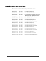
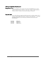
Sealevel Ethernet Serial Server Product Family
This manual covers the installation and operation of these devices:
SeaLINK.232
(P/N 4101)
- 1 Port RS-232 Serial Server
SeaLINK.485
(P/N 4102)
- 1 Port RS-422/485 Serial Server
SeaLINK.Ultra
(P/N 4103)
- 1 Port Isolated RS-232/422/485 Serial Server
With Isolated Input and Reed Relay Output
SeaLINK.Multi
(P/N 4104)
- 1 Port RS-232/422/485 Serial Server
SeaLINK+2.232
(P/N 4201)
- 2 Port RS-232 Serial Server
SeaLINK+2.485
(P/N 4202)
- 2 Port RS-422/485 Serial Server
SeaLINK+2.Multi (P/N 4203)
- 2 Port RS-232/422/485 Serial Server
SeaLINK+4.232
(P/N 4401)
- 4 Port RS-232 Serial Server
SeaLINK+4.422
(P/N 4402)
- 4 Port RS-422/485 Serial Server
SeaLINK+4.Ultra (P/N 4403)
- 4 Port RS-232/422/485 Serial Server
SeaLINK+8.232
(P/N 4801)
- 8 Port RS-232 Serial Server
SeaLINK+8.422
(P/N 4802)
- 8 Port RS-422/485 Serial Server
SeaLINK+8.Ultra (P/N 4803)
- 8 Port RS-232/422/485 Serial Server
SeaLINK+16.232
(P/N 4161)
- 16 Port RS-232 Serial Server
SeaLINK+16.422
(P/N 4162)
- 16 Port RS-422/485 Serial Server
SeaLINK+16.Ultra (P/N 4163)
© Sealevel Systems, Inc.
-2-
- 16 Port RS-232/422/485 Serial Server
SeaLINK User Manual
Before You Get Started
What’s Included
All Ethernet serial servers ship with the following items. If any of these items is
missing or damaged, please contact Sealevel for a replacement.
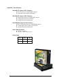
Ethernet Serial Server – (see part numbers on previous page)
Power Supply – (described below)
Ethernet Patch Cable – Item# CA246, 7’ Ethernet patch cable (blue)
Ethernet Crossover Cable – Item# CA251, 7’ Ethernet crossover cable (yellow)
Serial Loopback – (described below)
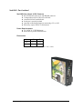
Sealevel Software CD – includes SeaLINK software and PDF manuals
Printed QuickStart Guide
Power Supplies
The following power supplies are included with the corresponding Ethernet serial
server listed below. Replacement power supplies can be purchased from the Sealevel
website.
Item# TR101 – 5VDC/120VAC @ 3A power adapter
Ships with: 4401, 4402, 4403, 4801, 4802, and 4803
Item# TR104 – 12VDC/120VAC @ 500mA power adapter
Ship with: 4103 only
Item# TR107 – 5VDC/120VAC @ 1A power adapter
Ships with: 4101, 4102, 4104, 4201, 4202, and 4203
Item# TR125 – 12VDC/120VAC @ 1A power adapter
Includes locking barrel connector
Ships with: 4161, 4162, and 4163
Loopback Adapters
All Ethernet serial servers with DB9M connectors include a 9-pin serial loopback
adapter, item# LB101. Only the data pins are looped back on the LB101.
For Ethernet serial servers with RJ45 connectors, the following loopback adapters are
included:
Item# LB117 (Red) – RS-232 loopback plug, ships with 4161 and 4163
Item# LB118 (Yellow) – RS-422 loopback cable, ships with 4162 and 4163
Item# LB119 (Green) – RS-485 loopback cable, ships with 4162 and 4163
© Sealevel Systems, Inc.
-3-
SeaLINK User Manual
Optional Items
Depending upon your application, you are likely to find one or more of the following
items useful for interfacing the Ethernet serial servers to real-world signals.
All items can be purchased from our website (http://www.sealevel.com) or by calling
864-843-4343. For applicable accessories, pin out diagrams are located on the
website.
CA127 – DB9 female to DB9 male serial extension cable. Extends a DB9 serial
connection by 72”.
CA177 – DB9 female to DB25 males modem cable, 72” in length. A standard
RS-232 modem cable providing a convenient connection to serial peripherals
with DB25 connectors. Connects to the host system via a DB9 connector.
CA246 – Standard CAT5e UTP patch cable, 7’ in length (blue).
CA247 – Standard CAT5e UTP patch cable, 10’ in length (blue).
CA251 – Standard CAT5e UTP crossover cable, 7’ in length (yellow).
RJ9P8 – A modular adapter with an RJ45 female connector and a DB9 male
connector. Ships unassembled and can be easily configured without tools for
virtually any pin out.
DB116 – A modular adapter with an RJ45 female connector and a DB9 male
connector preconfigured for RS-232 pin out. Use standard network patch cables
to connect RJ45 equipped serial servers to RS-232 serial peripherals with
standard DB9 connectors.
TB05 – A terminal block with a DB9 female connector breaking out to 9 screw
terminals. Simplifies field wiring of RS-422/485 networks with differing pin out
configurations.
TBRJ45 – A terminal block with an RJ45 female connector breaking out to 9
screw terminals. Converts field wiring to an RJ45 connection. Simplifies remote
RS-422/485 wiring to RJ45 equipped serial servers.
DR103 – DIN-rail mounting clip for the 4103 Ethernet serial server.
DR104 – DIN-rail mounting clips for 4-port and 8-port Ethernet serial servers.
Additional accessories are available at http://www.sealevel.com/accessories.asp
© Sealevel Systems, Inc.
-4-
SeaLINK User Manual
Hardware Description
Common Product Features
Ethernet 10/100BaseT (auto sense)
Appears as virtual COM port to host machine
Data rates to 230.4K bps
Hot-swappable
Built-in watchdog/reset circuit for fault tolerance
Specifications
Environmental Specifications
Specification
Temperature Range
Humidity Range
© Sealevel Systems, Inc.
Operating
0°C – 70°C
(32°F – 158°F)
10 to 90% R.H.
Non-Condensing
-5-
Storage
-50°C – 105°C
(-58°F – 221°F)
10 to 90% R.H.
Non-Condensing
SeaLINK User Manual
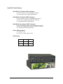
SeaLINK 1-Port Devices
SeaLINK.232 (Item# 4101) Features
RS-232 serial server with DB-9M connector
All modem control signals implemented
SeaLINK.485 (Item# 4102) Features
RS-422/485 serial server with DB-9M connector
Configurable for RS-422 or RS-485
Automatic RS-485 enable/disable
SeaLINK.Multi (Item# 4104) Features
RS-232/422/485 serial server with DB-9M connector
Configurable for RS-232, RS-422 or RS-485
Automatic RS-485 enable/disable
Power Requirements
+5VDC @ 500mA
2.1mm x 5.5mm center positive
Dimensions
L*
W
H
5.00”
4.17”
1.14”
127mm
106mm
29mm
* Length includes non-removable ears
© Sealevel Systems, Inc.
-6-
SeaLINK User Manual
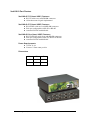
SeaLINK 1-Port Isolated
SeaLINK.Ultra (Item# 4103) Features
RS-232/422/485 serial server with DB-9M connector
Configurable for RS-232, RS-422 or RS-485
Automatic RS-485 enable/disable
Serial port is optically isolated
Optically isolated digital input for monitoring +5V to +24V
Reed relay output: 60VDC @ 500mA max
Power Requirements
+9-30VDC @ 3.25W Minimum
Removable 6-position terminal block
Dimensions
L*
W
H
4.45”
4.17”
1.14”
113mm
106mm
29mm
* Length including removal terminal block is 4.84” (123mm)
© Sealevel Systems, Inc.
-7-
SeaLINK User Manual
SeaLINK 2-Port Devices
SeaLINK+2.232 (Item# 4201) Features
RS-232 serial server with DB-9M connectors
All modem control signals implemented
SeaLINK+2.485 (Item# 4202) Features
RS-422/485 serial server with DB-9M connectors
Each port configurable for RS-422 or RS-485
Automatic RS-485 enable/disable
SeaLINK+2.Multi (Item# 4203) Features
RS-232/422/485 serial server with DB-9M connectors
Each port configurable for RS-232, RS-422 or RS-485
Automatic RS-485 enable/disable
Power Requirements
+5VDC @ 500mA
2.1mm x 5.5mm center positive
Dimensions
L*
W
H
5.00”
4.17”
1.14”
127mm
106mm
29mm
* Length includes non-removable ears
© Sealevel Systems, Inc.
-8-
SeaLINK User Manual
SeaLINK 4-Port Devices
SeaLINK+4.232 (Item# 4401) Features
RS-232 serial server with DB-9M connectors
All modem control signals implemented
SeaLINK+4.422 (Item# 4402) Features
RS-422/485 serial server with DB-9M connectors
Each port configurable for RS-422 or RS-485
Automatic RS-485 enable/disable
SeaLINK+4.Ultra (Item# 4403) Features
RS-232/422/485 serial server with DB-9M connectors
Each port configurable for RS-232, RS-422 or RS-485
Automatic RS-485 enable/disable
Power Requirements
+5VDC @ 1A
2.1mm x 5.5mm center positive
Dimensions
L
W
H
8.62”
6.10”
2.00”
219mm
155mm
51mm
© Sealevel Systems, Inc.
-9-
SeaLINK User Manual
SeaLINK 8-Port Devices
SeaLINK+8.232 (Item# 4801) Features
RS-232 serial server with DB-9M connectors
All modem control signals implemented
SeaLINK+8.422 (Item# 4802) Features
RS-422/485 serial server with DB-9M connectors
Each port configurable for RS-422 or RS-485
Automatic RS-485 enable/disable
SeaLINK+8.Ultra (Item# 4803) Features
RS-232/422/485 serial server with DB-9M connectors
Each port configurable for RS-232, RS-422 or RS-485
Automatic RS-485 enable/disable
Power Requirements
+5VDC @ 1A
2.1mm x 5.5mm center positive
Dimensions
L
W
H
8.62”
6.10”
2.00”
219mm
155mm
51mm
© Sealevel Systems, Inc.
- 10 -
SeaLINK User Manual
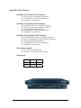
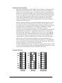
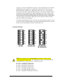
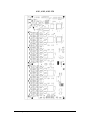
SeaLINK 16-Port Devices
SeaLINK+16.232 (Item# 4161) Features
RS-232 serial server with RJ45 connectors
Transmit/Receive LEDs on each RJ45 port
Standard 19” rack enclosure
SeaLINK+16.422 (Item# 4162) Features
RS-422/485 serial server with RJ45 connectors
Each port configurable for RS-422 or RS-485
Automatic RS-485 enable/disable
Transmit/Receive LEDs on each RJ45 port
Standard 19” rack enclosure
SeaLINK+16.Ultra (Item# 4163) Features
RS-232/422/485 serial server with RJ45 connectors
Each port configurable for RS-232, RS-422 or RS-485
Automatic RS-485 enable/disable
Transmit/Receive LEDs on each RJ45 port
Standard 19” rack enclosure
Power Requirements
+9-30VDC @ 10W Minimum
2.5mm x 5.5mm center positive, locking
Dimensions
L*
W
H
16.75”
7.00”
1.75”
219mm
155mm
51mm
* Length excludes removable ears.
© Sealevel Systems, Inc.
- 11 -
SeaLINK User Manual
Hardware Configuration
SeaLINK devices supporting RS-422/485 need to be properly configured prior to
installation. The configuration requirements for each device are outlined below.
Note: The following devices do not require any hardware settings and the
enclosures should not be opened. All configurations settings can be made through
the SeaLINK driver and/or the device’s onboard web page:
4101 – 1-port RS-232 serial server
4201 – 2-port RS-232 serial server
4401 – 4-port RS-232 serial server
4801 – 8-port RS-232 serial server
4161 – 16-port RS-232 serial server
4162 – 16-port RS-422/485 serial server
4163 – 16-port RS-232/422/485 serial server
Single and Dual Port Serial Servers
SeaLINK one and two port multi-interface devices are configured by setting
dipswitches inside the enclosure and by changing configuration options through the
onboard web server. The electrical interface (RS-232, RS-422, or RS-485) for each
port must be set properly in both places. The hardware default is RS-422 mode. This
section covers the configuration of the following serial servers:
4102 – 1-port RS-422/485 serial server
4104 – 1-port RS-232/422/485 serial server
4202 – 2-port RS-422/485 serial server
4203 – 2-port RS-232/422/485 serial server
NOTE:
The configuration settings for the 4103 are covered in the next
section.
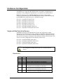
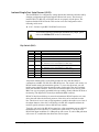
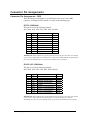
Dipswitches
Switch
1
2
3
4
5
6
Label
M1
M0
L
L
T
PD
7
PU1
8
PU2
© Sealevel Systems, Inc.
Function
Set to On
On for RS-485, Off for RS-232/422
Link TX- to RX- for RS-485 two wire operation
Link TX+ to RX+ for RS-485 two wire operation
Adds or removes the 120Ω termination
Adds or removes the 1KΩ pull-down resistor in the
RS-422/485 receiver circuit (Receive data only).
Adds or removes the 1KΩ pull-up resistor in the
RS-422/485 receiver circuit (Receive data only)
Adds or removes the 4.7KΩ pull-up resistor in the
RS-422/485 CTS circuit (compensates for RS-232 biasing)
- 12 -
SeaLINK User Manual
Dipswitches (continued)
Dipswitches on the PCB provide SeaLINK devices the ability to communicate with
RS-232, RS-422 or RS-485 devices. These switches are also used to set RS-485
enable modes and termination options. The 4102 and 4104 have a single dipswitch
labeled (S2). On the 4202 and 4203, a pair of dipswitches are labeled (S2) and (S3).
To access the dipswitches, you will need to remove the PCB from the metal housing.
On the end of the device with the DB9 connector, remove the two black machine
screws and set aside. Make sure you are properly grounded before proceeding.
Gently slide the PCB out of the housing. The dipswitches are located on the PCB
adjacent to the DB9 connector.
RS-485 is ideal for multi-drop or network environments. RS-485 requires a tri-state
driver that will allow the electrical presence of the driver to be removed from the
line. The driver is in a tri-state or high impedance condition when this occurs. One of
the unique features of SeaLINK devices is the ability to be RS-485 compatible
without the need for special software or drivers (RS-485 auto-enable).
Typically, each end of the RS-485 bus must have a line-terminating resistor (RS-422
terminates the receive end only). A 120Ω resistor (silk-screen ‘T’) is across each
RS-422/485 input in addition to a 1KΩ pull-up (silk-screen ‘PU1’) and a 1KΩ pull
down (silk-screen ‘PD’) combination that biases the receiver inputs. The SeaLINK
device has RS-232 transceivers with built-in biasing, even when disabled. This is
compensated for by adding a 4.7KΩ pull-up (silk-screen ‘PU2) to the CTS circuit.
Only the ends of an RS-485 network should have the 120Ω terminating resistor.
These resistors may be removed or inserted using the dipswitch “T”. This allows the
user to customize the electrical interface to their specific requirements. Each switch
position corresponds to a specific portion of the interface.
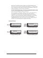
To add the termination/bias resistors, select the ‘On’ position, and to remove it, select
the ‘Off’ position. If multiple adapters are configured in an RS-485 network, only the
boards on each end should have switches T, PD, PU1 & PU2 ‘On’.
Example Settings
© Sealevel Systems, Inc.
- 13 -
SeaLINK User Manual
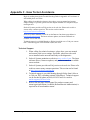
Isolated Single Port Serial Server (4103)
The SeaLINK 4103 is configured by setting dipswitches inside the enclosure and by
changing configuration options through the onboard web server. The electrical
interface (RS-232, RS-422, or RS-485) must be set properly in both places. The
hardware default is RS-422 mode. This section covers the configuration of the
following serial server:
4103 – Isolated 1-port RS-232/422/485 serial server
NOTE:
To access the optically isolated input and Reed relay output, please
refer to the Modbus TCP section of this manual.
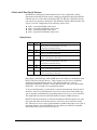
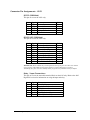
Dip Switch (SW1)
Switch
1
2
3
4
5
Label
1
2
3
T
P
6
P
7
8
9
10
L
L
E
-
Function
On for RS-232, Off for RS-422/485
On for RS-485, Off for RS-232/422
On for RS-422/485, Off for RS-232
Adds or removes the 120Ω termination
Adds or removes the 1KΩ pull-down resistor in the
RS-422/485 receiver circuit (Receive data only)
Adds or removes the 1KΩ pull-up resistor in the
RS-422/485 receiver circuit (Receive data only)
Connects the TX+ to RX+ for RS-485 two wire operation
Connects the TX- to RX- for RS-485 two wire operation
On for No Echo, Off for Echo
Not Used
A dipswitch labeled (SW1) on the PCB provides the 4103 with the ability to
communicate with RS-232, RS-422 or RS-485 devices. The switch is also used to set
RS-485 enable modes and termination options. To access the dipswitch, you will
need to remove the PCB from the metal housing. On the end of the device with the
RJ45 jack and DB9 connector, remove the two black machine screws and set aside.
Make sure you are properly grounded before proceeding. Gently slide the PCB out of
the housing. The dipswitch is located just behind the DB9 connector.
RS-485 is ideal for multi-drop or network environments. RS-485 requires a tri-state
driver that will allow the electrical presence of the driver to be removed from the
line. The driver is in a tri-state or high impedance condition when this occurs. One of
the unique features of the 4103 is the ability to be RS-485 compatible without the
need for special software or drivers (RS-485 auto-enable).
Typically, each end of the RS-485 bus must have a line-terminating resistor (RS-422
terminates the receive end only). A 120Ω resistor (silk-screen ‘T’) is across each
RS-422/485 input in addition to a 1KΩ pull-up (silk-screen ‘P’) and a 1KΩ pull down
(silk-screen ‘P’) combination that biases the receiver inputs.
© Sealevel Systems, Inc.
- 14 -
SeaLINK User Manual
Only the ends of an RS-485 network should have the 120Ω terminating resistor.
These resistors may be removed or inserted using the dipswitch ‘T’. This allows the
user to customize the electrical interface to their specific requirements. Each switch
position corresponds to a specific portion of the interface.
To add the termination/bias resistors, select the ‘On’ position, and to remove it, select
the ‘Off’ position. If multiple adapters are configured in an RS-485 network, only the
boards on each end should have switches T, P & P ‘On’.
The last option that is configurable via SW1 is the ‘Echo’ option (silk-screen ‘E’).
Two-wire RS-485 connects the TX± to the RX±. Every time a character is
transmitted it is also received. This can be beneficial if the software can handle
echoing (i.e. using received characters to throttle the transmitter), or it can confuse
the system if the software does not. Switch 9 is used to control the RS-485
enable/disable functions for the receiver circuit. To select the ‘No Echo’ mode set
switch 9 to ‘On’. The following shows example switch settings.
Example Settings
© Sealevel Systems, Inc.
- 15 -
SeaLINK User Manual
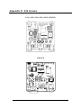
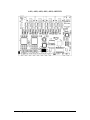
4-Port and 8-Port Serial Servers
SeaLINK four and eight port multi-interface devices are configured by setting
dipswitches inside the enclosure and by changing configuration options through the
onboard web server. The electrical interface (RS-232, RS-422, or RS-485) for each
port must be set properly in both places. The hardware default is RS-422 mode. This
section covers the configuration of the following serial servers:
4402 – 4-port RS-422/485 serial server
4403 – 4-port RS-232/422/485 serial server
4802 – 8-port RS-422/485 serial server
4803 – 8-port RS-232/422/485 serial server
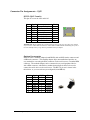
Dipswitches
Switch
1
Label
EN
2
3
T
PD
4
PU
5
EN
6
7
T
PD
8
PU
Function
On for RS-422/485, Off for RS-232 - Adds or removes the 4.7K Ω
pull-up resistor in the RS-422/485 CTS circuit
(Compensates for RS-232 biasing)
Adds or removes the 120Ω termination
Adds or removes the 1KΩ pull-down resistor in the RS-422/485
receiver circuit (Receive data only)
Adds or removes the 1KΩ pull-up resistor in the RS-422/485
receiver circuit (Receive data only)
Dipswitches on the PCB provide SeaLINK devices the ability to communicate with
RS-232, RS-422 or RS-485 devices. These switches are also used to set RS-485
enable modes and termination options. The 4402 and 4403 have a pair of
dipswitches labeled (S3) and (S4). On the 4802 and 4803, four sets of dipswitches,
labeled (S1 – S4), are used to set configuration options.
To access the dipswitches, you will need to open the metal housing. On each side of
the device, remove two black machine screws (four total) and set aside. Make sure
you are properly grounded before proceeding. Remove the cover to access the PCB.
The dipswitches are located on the PCB behind each pair of DB9 connectors.
RS-485 is ideal for multi-drop or network environments. RS-485 requires a tri-state
driver that will allow the electrical presence of the driver to be removed from the
line. The driver is in a tri-state or high impedance condition when this occurs. One of
the unique features of the SeaLINK device is the ability to be RS-485 compatible
without the need for special software or drivers.
© Sealevel Systems, Inc.
- 16 -
SeaLINK User Manual
Typically, each end of the RS-485 bus must have a line-terminating resistor (RS-422
terminates the receive end only). A 120Ω resistor (silk-screen ‘T’) is across each
RS-422/485 input in addition to a 1KΩ pull-up (silk-screen ‘PU’) and a 1KΩ pull
down (silk-screen ‘PD’) combination that biases the receiver inputs. Only the ends of
an RS-485 network should have the 120Ω terminating resistor. These resistors may
be removed or inserted using the dipswitches. This allows the user to customize the
electrical interface to their specific requirements. Each switch position corresponds to
a specific portion of the interface. Each group of four switches controls one serial
port (refer to PCB for port numbers).
To add the termination/bias resistors, select the ‘On’ position, and to remove it, select
the ‘Off’ position. If multiple adapters are configured in an RS-485 network, only the
boards on each end should have switches T, PD, & PU ‘On’.
Example Settings
NOTE: The following devices do not require any hardware settings and the
enclosures should not be opened. All configurations settings can be made through
the SeaLINK driver and/or the device’s onboard web page:
4101 – 1-port RS-232 serial server
4201 – 2-port RS-232 serial server
4401 – 4-port RS-232 serial server
4801 – 8-port RS-232 serial server
4161 – 16-port RS-232 serial server
4162 – 16-port RS-422/485 serial server
4163 – 16-port RS-232/422/485 serial server
© Sealevel Systems, Inc.
- 17 -
SeaLINK User Manual
SeaLINK Redirector Overview
Virtual COM Port Basics
SeaLINK software is a serial COM port redirector that creates virtual COM ports and
provides access to serial devices connected to a SeaLINK Ethernet serial server.
SeaLINK allows you to configure Microsoft Windows applications to communicate
with networked serial devices as easily as if they were physically installed in or
directly connected to the PC.
This means that your serial device applications can communicate with serial devices
connected to SeaLINK Ethernet serial servers without software changes. Since the
virtual COM ports work like standard Windows COM ports, your application
software sees no difference between a local serial device and one connected to a
SeaLINK Ethernet serial server.
The redirector (SeaLINK software) connects to the SeaLINK device (Ethernet serial
server) when an application opens the COM port and disconnects from the SeaLINK
device when the COM port is closed. The redirector uses TCP network connections
to the SeaLINK device to gain access to the connected serial devices.
The SeaLINK redirector can create up to 256 virtual COM ports, from COM1 to
COM256. Applications on the local computer can open virtual COM ports to use
multiple networked serial devices at the same time. The redirector handles each
active virtual COM port as a separate TCP connection to the SeaLINK device.
NOTE:
Some legacy applications are only able to use COM ports in the
range of COM1 to COM4, which limits the number of virtual COM
ports they can use.
Application Compatibility
Using a SeaLINK Ethernet serial server adds a network connection and the SeaLINK
device to the data path between an application and the serial device it is using. For
most applications, these differences are negligible. The SeaLINK software and
SeaLINK device both support the COM Port Control protocol (IETF RFC 2217),
which is designed to provide the best possible duplication of the behavior of a local
COM port. The software uses this network protocol to relay additional control and
signal information to the SeaLINK device.
SeaLINK software and devices fully support applications that need to control (at runtime) the baud rate, parity, framing, and status signals of serial devices connected to
the virtual COM ports. Serial port settings can also be configured on the SeaLINK
Ethernet serial server’s internal web page. Configuration settings on the SeaLINK
device can allow application changes or override them.
© Sealevel Systems, Inc.
- 18 -
SeaLINK User Manual
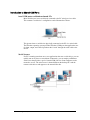
Introduction to Shared COM Ports
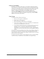
Local COM ports on Windows-based PCs
Most serial devices in use are directly connected to the PC serial port via a cable.
This common "local device" configuration can be illustrated as follows:
This picture shows a serial device physically connected to the PC via a serial cable.
The Windows operating system provides Windows COM ports that applications use
for input, output, and control operations that "reach" through the serial cable to the
device.
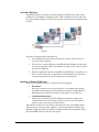
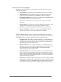
Serial Servers
If a PC is running more than one or two applications that use a serial device, you can
quickly run out of places to attach them. Fortunately, you can employ an Ethernet
serial server that provides a pool of virtual COM ports for client computers on the
network to access. The serial server is situated between the desktop PCs and the
remote serial devices and appears to the network like this:
© Sealevel Systems, Inc.
- 19 -
SeaLINK User Manual
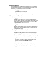
SeaLINK COM Ports
SeaLINK software is essentially an add-on package for Windows that adds virtual
COM ports to the Windows operating system. These COM ports can look and work
like conventional COM ports, but they are accessed on the serial server instead of the
local PC.
SeaLINK
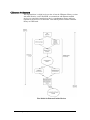
The pieces fit together in the following way:
1. You configure the serial server to provide one or more serial devices for
access by client computers.
2. For each of its virtual COM ports, SeaLINK uses the IP address of the serial
server on the network and the "port number" (socket) on the serial server that
provides the COM port.
3. When the application opens the SeaLINK virtual COM port, it actually sees a
device on the serial server. Connections are established just as if the device
were connected directly to the PC rather than over the network.
Benefits of Shared COM Ports
There are two primary benefits to a serial server-based approach:
1. Economical.
By using a serial server to share serial devices, you eliminate the separate
serial lines and devices that would otherwise be attached to individual PCs.
Monitoring the serial devices becomes easier and more cost effective.
2. Centralized Maintenance.
Serial servers concentrate all of the hardware required for serial device
communications into one location, typically a server room. This makes it
easier to setup, access and service the devices.
Although the serial server solves many of the hardware issues surrounding shared
serial resources, it does not tackle a primary software requirement: setting up the
Windows COM ports that most Windows communications software requires. This is
where SeaLINK software comes into the picture.
© Sealevel Systems, Inc.
- 20 -
SeaLINK User Manual
Device Configuration
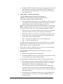
Locating the Device and Assigning an IP Address
Before the SeaLINK device can be used, it must be assigned an IP address valid to
your network. When first powered up, the device will attempt to automatically find
an IP address using DHCP. If the device is linked but cannot locate a DHCP server,
the link LED on the box will flash, indicating that the device does not have valid
network setting. In that case, you will need to assign it a static address using the
configuration utility provided. The configuration utility ‘SeaLINK Config’ (Start Æ
Programs Æ SeaLINK Æ SeaLINK Config) is also useful for locating devices to
determine the IP address. The method depends on your operating system, so see the
appropriate section below.
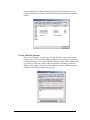
Device Configuration with Windows
Windows device configuration is performed through the ‘SeaLINK Config’ utility
provided with the software installation. When started, the utility will display all
devices on the local network (the utility cannot see devices on the other side of a
router). If your device is not listed, verify that it is connected to the network (see the
Troubleshooting section). To assign a static IP address, select your device in the list,
click ‘Settings, then uncheck the box that says “Enable DHCP.” Change the “IP”,
“Gateway”, and “Network Mask” fields to values valid on your network. You can
also change the “Name” of the device to something appropriate (i.e., location,
connected equipment, etc.). Click “Apply Changes” and the device will reboot and
temporarily disappear from view. You may need to click “Search Again” to relocate
the device. You can also set the IP Address, Gateway, Network Mask, and Device
Name through the onboard web server, discussed in the following sections.
Device Configuration with Linux
Refer to the Raw Data section of this manual.
© Sealevel Systems, Inc.
- 21 -
SeaLINK User Manual
SeaLINK Software Installation
This section provides instructions for both expert and novice Windows users on how
to install and configure the SeaLINK client. Experienced users will likely find
sufficient information in the printed QuickStart guide included with the device.
Those requiring more detailed instructions and serial server background information
should read through the rest of this manual to gain more familiarity with SeaLINK
software and virtual COM ports.
Pre-Installation Checklist
Before installing the SeaLINK client on your PC, you or an administrator should first
prepare your serial server for operation. The checklist below helps to ensure that both
your PC and serial server are ready for SeaLINK.
3 You are using an Intel-compatible PC with a Pentium class CPU running
Windows 98, ME, NT 4.0 SP6, 2000, XP SP1 (32-bit or 64-bit), Server 2003,
or Windows Vista™ (32-bit or 64-bit) operating systems.
3 Your PC has at least 4 megabytes of local disk storage for a complete
installation of SeaLINK software and documentation. The SeaLINK
installation program will place several small files in the Windows system
folder. All other files will be located in the installation directory that you
designate during installation.
3 Your PC is networked to a SeaLINK serial server on a TCP/IP network.
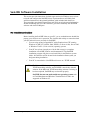
NOTE:
The Microsoft Windows operating systems include Microsoft’s
TCP/IP networking software, and SeaLINK is tested only with this
software. If the Microsoft TCP/IP networking software is missing or
has been replaced, SeaLINK may not function properly.
SeaLINK does not run under multi-user operating systems such
as Citrix Metaframe and Windows Terminal Services and is not
supported on Windows 95.
© Sealevel Systems, Inc.
- 22 -
SeaLINK User Manual
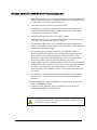
Windows 98/ME/NT/2000/XP/Vista™ Operating Systems
1. Start Windows and log in as a user with Administrator privileges and quit all
Windows applications that use COM ports. Make sure the SeaLINK device
is connected to power and a valid network port.
2. Insert the Sealevel Software CD into your CD drive.
3. If ‘Auto-Start’ is enabled for this drive, the CD menu will automatically
launch. If the menu does not appear, double-click on the ‘autorun’ file
located in the root directory of the CD.
4. When the menu appears, click on the ‘Install’ button.
5. On the next screen, type in or select the Part Number for your device from
the listing, then click the ‘Install Drivers’ button.
6. The Installation Wizard will start. SeaLINK will install the Ethernet port
redirector (SeaLINK) software and test utility (WinSSD) – affirm the license
agreement and installation begins.
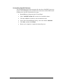
7. A screen may appear with the declaration: “The publisher cannot be
determined due to the problems below: Authenticode signature not found.”
Please select the ‘Yes’ button and proceed with the installation. This
declaration simply means that the Operating System is not aware of the
driver being loaded. It will not cause any harm to your system.
8. During setup the user may specify installation directories and other preferred
configurations. This program also adds entries to the system registry that are
necessary for specifying the operating parameters for each driver. An
uninstall option is also included to remove all registry/INI file entries from
the system.
9. A ‘readme.txt’ file will open. Please read the release notes and close. For
future reference, a copy of the text file can be found in the installation
directory.
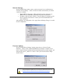
10. Once SeaLINK has completed installation, a window titled “Select Ports”
opens – CLOSE this window.
11. Continue with the following section for instructions on creating and
configuring SeaLINK virtual COM ports.
NOTE:
© Sealevel Systems, Inc.
SeaLINK software has been fully tested in Windows 98, ME, NT
4.0 SP6, 2000, Server 2003, XP (32-bit & 64-bit), and Vista™ (32bit & 64-bit) operating systems.
- 23 -
SeaLINK User Manual
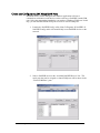
Create and Configure SeaLINK Virtual COM Ports
SeaLINK creates virtual COM ports that Windows applications will use to
communicate with remote serial devices on the serial server. SeaLINK virtual COM
ports follow the same naming/numbering convention as Windows COM ports. In this
step, you tell SeaLINK which serial ports to create as virtual COM ports.
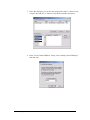
1. Launch the ‘SeaLINK Config’ utility (Start Æ Programs Æ SeaLINK Æ
SeaLINK Config) and it will automatically locate SeaLINK devices on the
network.
2. Select a SeaLINK device in the ‘Available SeaLINK Devices’ list. The
serial ports that can be assigned to virtual COM ports will be shown in the
‘Virtual COM Ports’ pane.
© Sealevel Systems, Inc.
- 24 -
SeaLINK User Manual
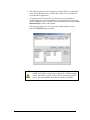
3. Select the serial ports you wish to map and press the Add ‘>’ button (or you
can press the Add All ‘>>’ button to map all the available serial ports).
4. In the ‘Local Virtual COM Port’ listing, select a starting virtual COM port
and click ‘Ok’.
© Sealevel Systems, Inc.
- 25 -
SeaLINK User Manual
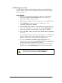
5. The selected serial ports will be mapped to virtual COM ports in sequential
order. The COM ports in the ‘Virtual COM’ listing are now available for
use by Windows applications.
For applications that use modems, you may want to run the Windows
modem installation wizard to install the correct modem driver for each new
virtual COM port used by a modem. This is explained in detail in the Create
Modem Devices section of this manual.
The next page explains how to test your new virtual COM ports using
Sealevel’s WinSSD diagnostic utility.
NOTE:
© Sealevel Systems, Inc.
Some legacy applications cannot display COM ports higher than
COM4. If you will be using a legacy application, consider selecting
ports in the COM 1-4 range. You may need to disable these COM
ports in the system BIOS to make them available to SeaLINK.
- 26 -
SeaLINK User Manual
WinSSD Diagnostic Utility
To verify operation of your virtual COM ports, Sealevel provides the WinSSD
diagnostic utility. WinSSD is part of the SeaLINK software suite and is included
with the installation.
Using WinSSD
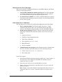
1. SeaLINK devices purchased from Sealevel ship with a serial loopback
adapter (See the Before You Get Started section of this manual for
loopback part numbers and descriptions).
2. Plug the loopback adapter into the first serial port on your SeaLINK device.
3. Launch WinSSD by clicking “Start”, click “All Programs”, click
“SeaLINK”, and then click “WinSSD”.
4. In the WinSSD window, under the “Port Information” tab, click the arrows
or type in the COM: number you created with the SeaLINKConfig utility.
5. Click on the “Loopback” tab and click the “Start” button in WinSSD.
6. Click on the “Help” button on each tab of the WinSSD utility for additional
instructions.
7. A successful test confirms that your Sealevel USB device is communicating
properly. Repeat the test for each additional serial port on your device;
otherwise click the “Exit” button to close the WinSSD utility.
8. Proceed with Additional SeaLINK Configuration Options on the
following page, or continue with the Onboard Web Server Configuration
section of this manual for additional device settings.
9. If you experience any configuration or testing problems with SeaLINK or
WinSSD, refer to the Troubleshooting section at the end of this manual.
NOTE:
© Sealevel Systems, Inc.
WinSSD can also be found on the Sealevel Software CD:
[CD drive]:\Software\Utilities\SeaLINK\WinSSD.exe
- 27 -
SeaLINK User Manual
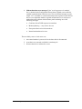
Additional SeaLINK Configuration Options
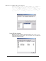
In the ‘Virtual COM’ ports listing in the ‘Virtual COM Ports’ pane, you should see a
listing of all virtual COM ports assigned to the selected device. If you need to
remove a virtual COM port, select the ports you want to remove and click the remove
‘<’ button (or click the remove all ‘<<’ button) to un-map the virtual COM ports. In
the example from above, virtual COM ports 3 and 5 have been removed (as shown
below).
Virtual COM Port Summary
When you click on the ‘Summary’ button (shown above), you’ll see a list of all the
virtual COM ports in use by the system. The ‘Device Name’ listing shows the virtual
COM ports assigned by SeaLINK.
© Sealevel Systems, Inc.
- 28 -
SeaLINK User Manual
In the example below, COM8 had been assigned previously, but the device is no
longer available on the network. SeaLINK only displays the IP address assigned to
COM8.
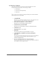
Virtual COM Port Cleanup
Click on the “Cleanup…” button (just above the ‘Summary’ button shown on the
previous page) to fix the broken COM8 assignment from the example above. In the
example shown below, the ‘Virtual COM Port Cleanup’ utility found COM8 and asks
if you want to un-map the virtual COM port and make it available for future use.
Simply click the ‘Remove Unused Virtual COM Ports’ button. COM8 will now be
available to SeaLINK to assign to other devices.
© Sealevel Systems, Inc.
- 29 -
SeaLINK User Manual
Network Settings
In the SeaLINK Setup window, make a selection from the list of available devices.
Click the ‘Device Settings...’ button. In the new window (shown below), the follow
controls are available:
Enable DHCP Configuration - When checked, the device will seek out a
DHCP server for automated configuration of its network parameters.
•
IP Address, Network mask, Gateway - These IP addresses configure how the
device responds on the network. Contact your network administrator for
more information.
After updating your configuration, click ‘Apply Network Settings Changes’ to enable
the new configuration.
•
Firmware Updates
In the ‘SeaLINK Device Settings’ window (shown above), click the ‘Update
Firmware...’ button. In the ‘Update SeaLINK Device Firmware’ window (shown
below), click the ‘Browse’ button and locate the firmware file you wish to apply. All
firmware files end in ‘_APP.s19’ as shown. Select your file and click the ‘Begin
Update’ button.
NOTE:
© Sealevel Systems, Inc.
All new firmware update files are located on the Sealevel FTP site:
ftp://ftp.sealevel.com/pub/software/sealink/firmware/current/
- 30 -
SeaLINK User Manual
Uninstalling SeaLINK Software
The SeaLINK uninstall procedure automatically shuts down SeaLINK if necessary,
removes all SeaLINK files from your hard drive, and removes all SeaLINK virtual
COM ports for your PC. Follow these easy steps:
•
Run Add/Remove Programs in the Control Panel.
•
Select ‘SeaLINK Version 4.5’ from the list of installed software.
•
Click the Add/Remove button to start the uninstall wizard.
•
In the ‘Select Uninstall Method’ dialog, choose the default, Automatic.
•
Click Next, and then click Finish.
•
Restart your computer to complete the uninstall process.
© Sealevel Systems, Inc.
- 31 -
SeaLINK User Manual
Raw Data Sockets
Raw Data Sockets are probably the easiest way for a software developer to control a
serial port, but provide the least control from a software standpoint. You simply
configure the device’s webpage to operate in Raw Data mode, open a socket to the
device on the Raw Data TCP port corresponding to the serial port you want, and
stream data back and forth. The data will not be inspected or modified in any way.
This method provides the least control because serial port functions such as baud rate
and modem control signals cannot be monitored or changed programmatically.
However, Raw Data is platform-independent and requires no software installation. If
your purposes do not require dynamic serial port control, Raw Data may be the most
efficient choice for you.
1. Configuration
•
Since Raw Data does not allow for programmatic changing of serial port
controls, the serial ports must be configured before use via the onboard web
server (see the Web Configuration section). From the Port Settings page,
configure the ports to the desired settings and click Submit at the bottom of
the page. The serial ports will automatically be set to these defaults when
opened Selection).
2. Usage Details
•
To access a serial port using Raw Data mode, open a TCP socket to the
device’s IP address on port 4760, which corresponds to the serial port on the
device.
Device Serial Port
1
2
3
4
5
6
7
8
9
10
11
12
13
14
15
16
NOTE:
© Sealevel Systems, Inc.
TCP Port Number (Socket)
4760
4761
4762
4763
4764
4765
4766
4767
4768
4769
4770
4771
4772
4773
4774
4775
Only one client can open each serial port at a time. All further
socket requests to a TCP port will be denied.
- 32 -
SeaLINK User Manual
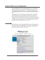
Onboard Web Server Configuration
Once the SeaLINK device has been assigned an IP address, you can configure it
through the onboard web server. Start the SeaLINK setup and configuration tool,
select your device, and click ‘Advanced…’. Alternately, you may open a web
browser (Internet Explorer, Firefox, Netscape, etc.) and type ‘http://xxx.xxx.xxx.xxx’
into the URL field, where ‘xxx.xxx.xxx.xxx’ is the IP address of the SeaLINK
device.
The configuration utility ‘SeaLINK Config’ (Start Æ Programs Æ SeaLINK Æ
SeaLINK Config) can be used to determine the IP address. The web interface
provides three separate pages selectable by tabs on the left side of the screen. A
Summary page lists various details about the device, a Port Settings page allows you
to configure aspects of each serial port, and an Administration page lets you change
the network and security settings. Some options or settings may not be available
depending on the model SeaLINK device you are using.
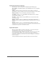
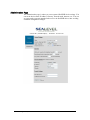
Summary Page
The Summary page lists the name of the SeaLINK device and part number. A user
defined device name is shown in parenthesis and can be set on the Administration
page. A brief description of the SeaLINK device capabilities is shown and the
Product Specifications and Settings section follows.
© Sealevel Systems, Inc.
- 33 -
SeaLINK User Manual
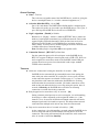
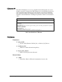
Product Specifications and Settings
The following is a list of settings that are displayed on the Summary page.
MAC Address – The hardware address of the SeaLINK device. This is assigned at
the factory.
Uptime – Displays the amount of time (in days, hours, minutes, seconds) the
SeaLINK device has been running since the last power interruption or device reboot.
Firmware Version – The version number of the firmware installed.
Uses DHCP – Displays ‘Yes’ if using DHCP set IP Address and ‘No’ if using a
static IP Address. Default is ‘Yes’.
IP Address – Address number set by the DHCP server or set by the user on the
Administration page.
Gateway – Default is ‘(not set)’. A Gateway is a point of entry to and from an
Ethernet network; a node that translates between two different networks or network
segments
Netmask – Default is ‘(not set)’. The Netmask (Network Mask) is used by the
TCP/IP protocol to decide how the network is divided into sub-networks and is used
to identify the local portion of an Ethernet network.
Supported Protocols
RFC-2217 Telnet COM Port (TCP Ports 4680-4687) – the protocol used by the
SeaLINK Windows driver and any socket based application
Unformatted Streamed Data (TCP Ports 4760-4767) – the protocol used for socket
based communications. When a port is opened, all data sent over Ethernet is
transmitted to COM port(s) and all data received from COM port(s) is transmitted
back over network.
As they are added to the firmware, support for other protocols may be listed.
© Sealevel Systems, Inc.
- 34 -
SeaLINK User Manual
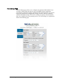
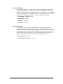
Port Settings Page
The Port Settings page allows you to configure each serial port individually. If you
are using a virtual serial port protocol such as SeaLINK software, application
programs may change these settings dynamically after opening the ports. If you want
to prevent programs from changing these settings, click the “Always use defaults”
checkbox and submit changes. This can be useful if you specify a custom baud rate
that is not available from your operating system. The ‘Port Settings’ are explained in
detail on the following page.
© Sealevel Systems, Inc.
- 35 -
SeaLINK User Manual
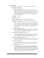
Port ‘x’ Defaults
The following is a list of settings that are displayed on the Port Settings page.
Default settings are in brackets:
Baud Rate – [57600] Text box
You can enter any number from 1to 921600, but Windows limits the
maximum baud rate to 230400. It may not be possible to hit the exact desired
baud rate, however the 16C950 compatible UART will attempt to set it as
closely as possible and will be within the acceptable 2% range. Enter any
valid baud rate and click Submit. The page will refresh and display the
nearest calculated baud rate.
Data Bits – 5, 6, 7, [8]
Stop Bits – [1], 1.5, 2
Parity – [none], even, odd, mark (forced 1), space (forced 0)
Flow Control – [none], Software (Xon/Xoff), Hardware (RTS/CTS)
RS Mode – [No Default], RS 232, RS 422, RS 485 (no echo), RS 485 (echo)
You should change this setting to match the electrical interface on the serial
device you are using. Certain SeaLINK devices also require dipswitches to
be properly configured – refer to the Hardware Configuration section for
more information. On multi-interface products, each port is individually
configurable.
Protocol – [Ignored], Modbus RTU
Enable if communicating with Modbus serial COM devices. When enabled,
the SeaLINK device won’t transmit until a full Modbus packet has been
received, which helps keep Modbus packets intact.
Termination – [Terminated], Non-Terminated
For SeaLINK devices with software selectable termination (currently 4162
and 4163) using RS-422 or RS-485 mode and no hardware termination
jumpers, this dropdown list can enable/disable line termination.
Input Alias – [None], DCD, DSR, RING
For the SeaLINK 4103, this sets the modem signal that the input is aliased to.
Refer to the 4103 Digital I/O section of this manual for more information.
Relay Alias – [None], DTR.
For the SeaLINK 4103, this sets the modem signal the relay is aliased to.
Refer to the 4103 Digital I/O section of this manual for more information.
‘Always use defaults’ – Checkbox
When using a virtual serial port protocol (SeaLINK software), application
programs may change the port settings dynamically after opening the ports.
To prevent programs from changing these settings, click the “Always use
defaults” checkbox and submit. This can be useful if you specify a custom
baud rate that is not available from your operating system. Applications can
still attempt changes, but the SeaLINK device will ignore them.
© Sealevel Systems, Inc.
- 36 -
SeaLINK User Manual
Connect to xxx . xxx . xxx . xxx : xxxx – Checkbox & IP/Port Address
To enable serial tunneling, click the checkbox and fill out the IP address and
TCP port number (socket) of the serial server you wish to connect to. When
the serial server detects serial data present on the serial port and no
connection is active, the serial server will connect to the IP address specified
on the webpage and send the data. SeaLINK devices support bidirectional
serial tunneling.
The TCP port number is the socket assigned to the COM port you are setting
up and the numbers range from 4680 to 4695. The first device’s serial port is
always port 4680 (regardless of virtual COM port mapping) and the numbers
increment by one, with the 16th serial port always being TCP port (socket)
4696.
For example, if you have a serial device connected to the 4th serial port of a
SeaLINK 4401 (four port device) that you want to set up to serial-tunnel to a
SeaLINK 4101 (single port device). On the webpage of the 4401, you type
the IP address of the 4101 with a TCP port number (socket) of 4680. If the
serial data is bidirectional, you will also set up serial tunneling on the 4101.
On the webpage of the 4101 you will type in the IP address of the 4401.
Since you are connecting to the 4th serial port, you will use TCP port number
4683. The table below illustrates the TCP port numbers (sockets) assigned to
the SeaLINK device serial ports.
Device Serial Port
1
2
3
4
5
6
7
8
9
10
11
12
13
14
15
16
© Sealevel Systems, Inc.
TCP Port Number (Socket)
4680
4681
4682
4683
4684
4685
4686
4687
4688
4689
4690
4691
4692
4693
4694
4695
- 37 -
SeaLINK User Manual
Administration Page
The Administration page is where you can set general SeaLINK device settings. You
can set the device name, IP address, Gateway, network mask, timeouts, etc. You can
set a password to prevent unauthorized access to the SeaLINK device, thus avoiding
accidental configuration changes.
© Sealevel Systems, Inc.
- 38 -
SeaLINK User Manual
General Settings
Name – Text box
This is the user assignable name of the SeaLINK device, useful for giving the
device a meaningful name (i.e., location, connected equipment, etc.)
Advertise (blink link LED) – On or [Off]
Set to ‘On’ and submit. The LINK LED will blink until it is disabled again.
This option only works on 4-port and 8-port SeaLINK devices. The 1-port, 2port, and 16-port SeaLINK devices do not have a LINK LED.
Nagle’s Algorithm – [Enable] or Disable
Referred to as “Nagling”, which is a method (IETF RFC 896) to reduce the
number of small packets transmitted over an Ethernet network. Devices that
support Nagling will buffer data until 1500 bytes have been received or
200ms has passed. Disable if serial COM devices are timing out due to
latency delays. You may have to disable Nagling at the host or network level
to further reduce host or network latency.
Note: Disabling Nagle’s Algorithm will increase packet traffic.
Connection Protocol – [RFC-2217] or Raw Data
Sets the connection protocol for all serial ports on the SeaLINK device.
RFC-2217 supports COM port control signals such as DTR, CTS, DCD, etc.
and is required for connections made via the SeaLINK virtual COM port
software. Raw has no protocol associated with it and accepts standard
TCP/IP socket connections.
Timeouts
Allow new connection if existing has been idle ‘x’ seconds: – [30]
SeaLINK devices automatically prevent multiple users from opening the
same serial port at the same time. If a serial port is in use (open), all other
socket connection requests are refused. Certain events (i.e., a system crash)
may break the serial connection without the SeaLINK device receiving
notification that the connection has ended. No further connections can be
made to that port unless the device is reset. By setting this option, after ‘x’
seconds of inactivity, the SeaLINK device will allow an incoming
connection to override the existing connection.
Retry dropped active connections every ‘x’ seconds: – [10]
Setting a timeout period prevents an active connection, via serial tunneling,
from trying to connect repeatedly to the assigned IP address (i.e., if the
timeout is set to 10 seconds, the failed serial tunnel connection will not be
attempted again until 10 seconds have passed). This helps reduce network
overhead where multiple serial devices may share the same network.
Drop active connections after ‘x’ seconds of inactivity: – [10]
Active connections, via serial tunneling, are made when the SeaLINK device
receives serial data and are closed when the receiving device closes the
connection. This setting will automatically disconnect the serial connection
after ‘x’ seconds of serial data inactivity.
© Sealevel Systems, Inc.
- 39 -
SeaLINK User Manual
Network Settings
(Force reboot on Submit) – changes will be reflected on Submit, but will not take
effect until SeaLINK device has been rebooted. The SeaLINK device defaults to
DHCP and will attempt to obtain an IP Address from a DHCP server. If an IP address
cannot be obtained from a valid DHCP server, you can set the device to a static IP
address. You can also assign a Gateway and Network Mask, if required.
Addressing – [DHCP] or Static
IP Address – Text box
Gateway – Text box
Netmask – Text box
Security Settings
You can assign a password to the SeaLINK device to prevent unauthorized
configuration changes via the web interface. Once a password has been set, a new
field appears next to the Submit button. You must enter the correct password and
press the Submit button before the SeaLINK device will accept new changes. The
password does not prevent the user from viewing the onboard web pages. If you
forget your password, see the Resetting to Factory Defaults section.
New Password – Text box
Confirm New Password – Text Box
© Sealevel Systems, Inc.
- 40 -
SeaLINK User Manual
Resetting to Factory Defaults
If you have forgotten your password or need to reset the device to the factory
defaults, manually browse to “http://xxx.xxx.xxx.xxx/debug.htm” (where
xxx.xxx.xxx.xxx is the IP Address of the SeaLINK device) and click the button
marked “Reset to Factory Defaults”. For the username, enter “debug”. In the
password field, type in the MAC address (no dashes or spaces) of the unit, located
either on the summary page or on the label on the bottom of the SeaLINK device.
The configuration utility ‘SeaLINK Config’ (Start Æ Programs Æ SeaLINK Æ
SeaLINK Config) can also be used to determine the MAC address number.
NOTE:
© Sealevel Systems, Inc.
The Debug Threshold settings on this page have no meaning to the
end user and are only used for factory testing and diagnostics. This
setting should be left set to ‘None’.
- 41 -
SeaLINK User Manual
Application Requirements
Check Application Requirements
Nearly all Windows applications can use SeaLINK virtual COM ports and remote
serial devices instead of direct-connected devices. Applications with special
requirements will usually work after properly configuring SeaLINK software and
hardware.
Most Windows applications perform only common read/write operations. Some
applications, however, require COM Port Control. SeaLINK serial servers support
COM Port Control, thus offering the degree of control that most of these special
applications require. Typically, the applications are one of three types:
1. Fax applications, which require very close interaction with the modem that
only COM Port Control can provide.
2. Custom applications that must set specific baud rates and framing. A
common workaround is to manually make these settings on the serial server.
3.
Custom applications, such as some data collection programs that connect to
remote equipment, which requires serial line status signals.
Create Modem Devices
Windows modem devices allow Windows applications to more easily use different
types of modems. Windows Dial-Up Networking, Windows HyperTerminal and
many other applications can and sometimes must use Windows modem devices. If
your application needs a specific modem device, as opposed to a COM port, follow
the instructions here to create a modem device for the remote modem on the server.
When you create a Windows modem device, you use Windows ‘Add Hardware’
wizard for modems found in the Windows Control Panel. You will need to answer
two basic questions:
1. What modem driver should be used for the remote modem?
2. What SeaLINK COM port reaches the remote modem? When prompted by
the wizard, choose the appropriate COM port from the list presented.
Choosing the Right Modem Definition (Modem Driver)
A common problem in using remote modems is a mismatch between the Windows
modem driver and the modem that is actually connected to the serial server. This
results from choosing the wrong modem driver when creating a Windows modem
device. Windows may already contain a modem definition for your modem,
especially if it is an external modem. If not, most modems usually ship with a CDROM containing the proper modem driver in the form of an INF file (a file with a
name ending in ".INF"). You can also obtain the correct driver from the modem
manufacturer’s website. It is very important that you use the correct modem driver
before you create the Windows modem device. If the wrong driver is installed for a
COM port, SeaLINK will not work.
© Sealevel Systems, Inc.
- 42 -
SeaLINK User Manual
Creating a Windows Modem Device
All versions of Windows include a hardware wizard that simplifies the process of
creating a modem device for a standard modem on a serial server. This wizard is
accessed through the Windows Control Panel. Because the wizard is implemented
slightly different in each Windows version, the following instructions are generalized
for all versions of Windows. Refer to your Windows documentation if additional
details are needed.
1. Determine the make and model of the modem(s) on the serial server.
2. Verify that the manufacturer of any modems connected to the serial server
has provided a modem driver file. If the original INF file cannot be located,
check the support pages on the manufacturer’s web site.
NOTE:
Windows includes a number of INF files for popular modems. The
hardware wizard will list these during the process of creating the
modem device.
Standard modems and generic drivers should be avoided.
3. Open the Windows Control Panel and click on the ‘Modems’ file or icon.
4. Click ‘Add’ to begin adding a new modem.
5. If Windows offers to detect the modem, check the box that prevents
automatic detection. You need to manually select the modem manufacturer
and model from a list.
6. You will now see the list of modem manufacturers and models directly
supported by Windows. In most cases, however, you will direct Windows to
the directory, diskette or CD-ROM containing the INF file for your modem.
7. Select the SeaLINK virtual COM port that will access the modem to
complete the process.
NOTE:
Windows typically lets you install the same driver for multiple ports
in one step, thus saving time.
8. Windows should now indicate that the modem has been successfully set up
and show which COM port SeaLINK is using. You may need to click on a
‘Properties’ button to see this information.
9. After installing the driver, it is highly recommended that you reboot your PC.
© Sealevel Systems, Inc.
- 43 -
SeaLINK User Manual
Application Settings & Examples
The final step in configuring an application is to change the application settings to
use either a SeaLINK COM port directly or the Windows modem device that refers
to the remote modem on the serial server. The general procedure is:
1. Find the ‘Settings’, ‘Preferences’, ‘Options’ command setting in the
application that allows you to specify the COM port or modem device to be
used by the program.
2. Choose the SeaLINK COM port, or the modem device that uses the
SeaLINK COM port, to access the remote modem.
NOTE:
Some older Windows applications do not recognize COM ports
higher than COM4, including some versions of Windows
HyperTerminal. If you need to use such an application, consider
creating COM ports in the COM1- COM4 range. You may need to
disable COM ports in your system BIOS to make them available to
the SeaLINK software.
Application Example: Sealevel WinSSD Utility
To verify operation of your virtual COM ports, Sealevel provides the WinSSD
diagnostic utility. WinSSD is part of the SeaLINK software suite and is included
with the installation.
Using WinSSD
1. SeaLINK devices purchased from Sealevel ship with a serial loopback
adapter (See the Before You Get Started section of this manual for
loopback part numbers and descriptions).
2. Plug the loopback adapter into the first serial port on your SeaLINK device.
3. Launch WinSSD by clicking “Start”, click “All Programs”, click
“SeaLINK”, and then click “WinSSD”.
4. In the WinSSD window, under the “Port Information” tab, click the arrows
or type in the COM: number you created with the SeaLINKConfig utility.
5. Click on the “Loopback” tab and click the “Start” button in WinSSD.
6. Click on the “Help” button on each tab of the WinSSD utility for additional
instructions.
7. A successful test confirms that your Sealevel USB device is communicating
properly. Repeat the test for each additional serial port on your device;
otherwise click the “Exit” button to close the WinSSD utility.
8. If you experience any configuration or testing problems with SeaLINK or
WinSSD, refer to the Troubleshooting section at the end of this manual.
NOTE:
© Sealevel Systems, Inc.
WinSSD can also be found on the Sealevel Software CD:
[CD drive]:\Software\Utilities\SeaLINK\WinSSD.exe
- 44 -
SeaLINK User Manual
Connector Pin Assignments
Connector Pin Assignments - DB9
The following pin out diagrams cover all Ethernet serial servers with a DB9
connector, excluding the 4103, which is covered on the following page.
RS-232 (DB9 Male)
This pin out covers the following products:
4101, 4104, 4201, 4203, 4401, 4403, 4801, and 4803
Pin # Signal Name
Mode
1
DCD Data Carrier Detect
Input
2
RX
Receive Data
Input
3
TX
Transmit Data
Output
4
DTR Data Terminal Ready Output
5
GND Ground
6
DSR Data Set Ready
Input
7
RTS Request To Send
Output
8
CTS Clear To Send
Input
9
RI
Ring Indicator
Input
Technical Note: Please terminate any control signals that are not going to be used. The most common
way to do this is connect RTS to CTS and RI. Also, connect DCD to DTR and DSR. Terminating these
pins, if not used, will help ensure you get the best performance from your adapter.
RS-422/485 (DB9 Male)
This pin out covers the following products:
4102, 4104, 4202, 4203, 4402, 4403, 4802 and 4803
Pin # Signal Name
1
RX+ Receive Data Positive
2
RX- Receive Data Negative
3
TX- Transmit Data Negative
4
TX+ Transmit Data Positive
5
GND Ground
6
RTS+ Request To Send Positive
7
RTS- Request To Send Negative
8
CTS- Clear To Send Negative
9
CTS+ Clear To Send Positive
Mode
Input
Input
Output
Output
Output
Output
Input
Input
Technical Note: Please terminate any control signals that are not going to be used. The most common
way to do this is connect RTS to CTS (connect positive to positive and negative to negative).
Terminating these pins, if not used, will help ensure you get the best performance from your adapter.
© Sealevel Systems, Inc.
- 45 -
SeaLINK User Manual
Connector Pin Assignments - 4103
RS-232 (DB9 Male)
This pin out covers the 4103 only.
Pin # Signal Name
2
RX
Receive Data
3
TX
Transmit Data
5
GND Ground
7
RTS Request To Send
8
CTS Clear To Send
Mode
Input
Output
Output
Input
RS-422/485 (DB9 Male)
This pin out covers the 4103 only.
Pin # Signal Name
1
RX+ Receive Data Positive
2
RX- Receive Data Negative
3
TX- Transmit Data Negative
4
TX+ Transmit Data Positive
5
GND Ground
6
RTS+ Request To Send Positive
7
RTS- Request To Send Negative
8
CTS- Clear To Send Negative
9
CTS+ Clear To Send Positive
Mode
Input
Input
Output
Output
Output
Output
Input
Input
Technical Note: Please terminate any control signals that are not going to be used. The most common
way to do this is connect RTS to CTS (connect positive to positive and negative to negative).
Terminating these pins, if not used, will help ensure you get the best performance from your adapter.
Relay / Input Connections
This pin out covers the removable terminal block on the 4103 only. Refer to the 4103
Digital I/O section for information on using the input and relay.
Pin # Signal Name
1
V+
9-30 VDC Input
2
VSupply Power Ground
3
Relay 2 Relay Contact 2
4
Relay 1 Relay Contact 1
5
Input 2 Optically Isolated Input
6
Input 1 Optically Isolated Input
© Sealevel Systems, Inc.
- 46 -
SeaLINK User Manual
Connector Pin Assignments – RJ45
RS-232 (RJ45 Female)
This pin out covers the 4161 and 4163.
Pin # Signal Name
Mode
1
RTS Request To Send
Output
2
DTR Data Terminal Ready Output
3
GND Ground
4
TX
Transmit Data
Output
5
RX
Receive Data
Input
6
DCD Data Carrier Detect
Input
7
DSR Data Set Ready
Input
8
CTS Clear To Send
Input
Technical Note: Please terminate any control signals that are not going to be used. The most common
way to do this is connect RTS to CTS. Also, connect DCD to DTR and DSR. Terminating these pins, if
not used, will help ensure you get the best performance from your adapter.
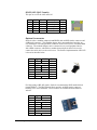
Optional Accessories
Sealevel offers a modular adapter (item# RJ9P8) with an RJ45 female connector and
a DB9 male connector. This modular adapter ships unassembled and provides an
easy method for converting the RJ45 connector on the serial server to a standard DB9
connector. The modular adapter can be connected to any serial peripheral device
with a DB9 connector, which allows standard network patch cables to be used to
connect the serial device to the serial server. The RS-232 pin out is shown in the
table below, or you can order one preconfigured (item# DB116).
RJ45
1
2
3
4
5
6
7
8
© Sealevel Systems, Inc.
Signal
RTS
DTR
GND
TX
RX
DCD
DSR
CTS
DB9M
7
4
5
3
2
1
6
8
Wire
Blue
Orange
Black
Red
Green
Yellow
Brown
White
- 47 -
SeaLINK User Manual
RS-422/485 (RJ45 Female)
This pin out covers the 4162 and 4163.
Pin # RS-422 RS-485 Name
Mode
1
TX+
Data+ Transmit Data + Output
3
GND
GND Ground
4
TX–
Data- Transmit Data – Output
5
RX+
Receive Data +
Input
8
RX–
Receive Data –
Input
Optional Accessories
Sealevel offers a modular adapter (item# RJ9P8) with an RJ45 female connector and
a DB9 male connector. This modular adapter ships unassembled and provides an
easy method for converting the RJ45 connector on the serial server to a standard DB9
connector. The modular adapter can be connected to any serial peripheral device
with a DB9 connector, which allows standard network patch cables to be used to
connect the serial device to the serial server. The Sealevel implementation of RS-422
is shown in the table below.
RJ45
1
2
3
4
5
6
7
8
Signal DB9M
TX+
4
No Connect
GND
5
TX–
3
RX+
1
No Connect
No Connect
RX–
2
Wire
Blue
Orange
Black
Red
Green
Yellow
Brown
White
For field wiring of RS-485 signals, Sealevel recommends the RJ45 terminal block
(item# TBRJ45). The RJ45 terminal block provides an RJ45 female connector
breaking out to screw terminals. All accessories are available from the Sealevel
website.
RJ45
1
2
3
4
5
6
7
8
© Sealevel Systems, Inc.
Signal Terminals
TX+
1
No Connect
GND
3
TX–
4
RX+
5
No Connect
No Connect
RX–
8
- 48 -
SeaLINK User Manual
4103 Digital I/O
Relay and Input Configuration
The 4103 has a single Reed relay output and a single optically isolated sensor input
for general purpose I/O. These functions are available either via a Modbus TCP
interface or as ‘aliased’ modem control signals. These functions are configured in
software via the onboard web server configuration interface section of this manual.
Refer to the following sections for Modbus TCP communication syntax and aliased
modem control signals.
Aliased Modem Control Signals
Modem control signals provide one the easiest and most convenient methods of
controlling the relay output and isolated input. In order to alias a modem control
signal, open the onboard web page for the 4103, and choose the Port Settings tab.
Choose a signal option for both the input alias and the relay alias.
For example, in order to control the relay output using the DTR modem control
signal, select DTR under the relay alias option and click ‘Apply’. Now, in order to
toggle the relay output, open a virtual COM connection to the serial port and toggle
the DTR signal. Refer to the Onboard Web Server section of this manual for
instructions on configuring the device via the onboard web server.
Modbus TCP
Modbus is a standard field bus protocol designed to make reading and writing I/O
device-independent. Modbus TCP is a variant of the Modbus protocol that uses
TCP/IP as its communication medium. Per the Modbus TCP specification, each I/O
point on a device is mapped to an address that can be specified within Modbus
commands. The mapped address is relative to the type of I/O.
The SeaLINK 4103 responds to zero-indexed ModBUS TCP requests and has one
relay output (readable/writeable bit) mapped as a coil at address 0, and one isolated
input (readable bit) mapped as a discrete input at address 0.
The 4103 responds to slave address 1 and accepts Modbus TCP connections on the
standard ModBUS TCP port 502.
Supported Modbus commands
READ_COILS
READ_DISCRETE_INPUTS
WRITE_SINGLE_COIL
WRITE_MULTIPLE_COILS
READ_DEVICE_IDENTIFICATION
(0x01)
(0x02)
(0x05)
(0x0f)
(0x2b)
Note: Some Modbus/TCP software is one-based, meaning that address ranges begin
with 1 instead of 0. For more information on Modbus/TCP or Modbus protocols, visit
http://www.modbus.org
© Sealevel Systems, Inc.
- 49 -
SeaLINK User Manual
CEthernet API
The CEthernet API is designed as an extension library that enables programmers to
develop applications to automatically find, configure, and use Ethernet-enabled
Sealevel devices. This library removes the manual hard-coding requirement of
locating a device on the network and replaces it with an automatic search function.
The CEthernet Development Libraries support the SeaI/O (Digital I/O) E-series and
SeaLINK (Ethernet Serial Servers) product families.
The source code contained in this document is designed to offer a high-level
overview of how to utilize the libraries contained on the Sealevel software CD-ROM
that ships with all SeaI/O modules. These code segments are meant as examples to
assist in your application development. Contact technical support regarding any
questions about the included code segments.
NOTE:
This library is not required to use any Sealevel Ethernet device.
© Sealevel Systems, Inc.
- 50 -
SeaLINK User Manual
CEthernet Architecture
The diagram below is a high-level overview of how the CEthernet Library co-exists
with other libraries, such as SeaLINK, to communicate with Ethernet-enabled
devices. As stated in the introduction, this is a supplementary library and is not
required for the device to be functional. Note that all packets from the CEthernet
library are UDP based.
Flow Model for Ethernet Enabled Devices
© Sealevel Systems, Inc.
- 51 -
SeaLINK User Manual
CEthernet API
The API to CCEthernet is easy to use, straightforward, and designed to be as userfriendly as possible. Looking at the UML diagram, one can determine that there are
only six functions that the interface provides. Of those, only four are required for
basic operation. Sample code segments are provided in a later section. Each of the
methods are documented below, including the parameters and the associated return
codes.
CCEthernet
-array
+CE
-objs
+CCEthernet()
+~CCEthernet()
+Alloc(in number : int)
+find_devices(in type_to_find : ceth_device_type, in number_to_find : int, inout list_to_store_devices : ceth_device *)
+Free(inout list : ceth_device *)
+get_number_of_interfaces()
+isWinsockInitialized()
-prepareList(inout c : ceth_device *, in n : int)
+set_information(inout device : ceth_device *, in command : ceth_set_types, in ... : ...)
UML Class Model for CCEthernet
find_devices
Parameters
type_to_find
−
number_to_find
−
Can be: SeaIO_Ethernet, SeaLink_Dev, or Sealevel_All_Devices.
number <= number allocated using Alloc().
list_to_store_devices
−
pointer to the list previously allocated.
Return Values
-100XX
−
Socket Error. Refer to Winsock documentation for error code.
© Sealevel Systems, Inc.
- 52 -
SeaLINK User Manual
set_information
Parameters
device
−
command
−
The device to modify the parameters of
Which parameters to modify, (SetIPAddress, SetDHCP, SetName).
...
−
This list is based off the command parameter above. For more information,
see below.
The variable argument list above, (denoted by the ...) is defined by which command
parameter is passed in. The commands can be logically OR'd together to make the
sequence easier. First, each command individually:
SetIPAddress
−
New IP Address
−
New Netmask
−
New Gateway
SetDHCP
−
None
SetName
−
New Name
If the IP configuration (DHCP or Static) is logically OR'd with the SetName option,
the parameters for the IP address must come first, and the last parameter will be the
name.
Return Values
-100XX
−
Socket Error. Refer to Winsock documentation for error code.
© Sealevel Systems, Inc.
- 53 -
SeaLINK User Manual
Alloc
Parameters
number
−
Number of devices to allocate space for. allocated.
Return Values
>0
−
Valid list.
-ENOMEM
−
Error allocating memory.
Free
Parameters
list
−
Pointer to the list previously allocated.
Return Values
None
NOTE:
© Sealevel Systems, Inc.
Because the allocation masks much of the socket communication,
the interface provides a mechanism to allocate and free the device
structures. It will not automatically perform this operation and use
of this library requires the explicit calls to Alloc() and Free().
- 54 -
SeaLINK User Manual
CEthernet Application Development
Using Visual C++
To use the CCEthernet Class, simply ensure that the SeaMAX directory is in the
include and library path for Visual C++. Once that is complete, simply include the
CEthernet.lib file is contained on the link tab settings for the project.
Required Code
For all of the following examples, the following must be in either the StdAfx.h file if
using Precompiled Header Files (PCH) or at the top of the individual C++ file. Once
these files are added, the code will know the definitions and locations for the
provided library.
#include
#include
#include
#include
© Sealevel Systems, Inc.
<stdio.h>
<windows.h>
<stdlib.h>
"CEthernet.h"
- 55 -
SeaLINK User Manual
Simple Find Using print_info Function
This section will show a simple find on all Sealevel Devices. There is a helper
function that is used to print out the information discovered about each unit. The
source code segment for the helper function is listed below.
void print_info(ceth_device_p c)
{
printf("Type : %s\n",
c->type==SeaIO_Ethernet?"SeaIO Ethernet"
:c->type==SeaLink_Dev?"SeaLink Device"
:"Who Knows?");
printf("Mac : %2.2X:%2.2X:%2.2X:%2.2X:%2.2X:%2.2X\n",
c->mac_address.c[0],
c->mac_address.c[1],
c->mac_address.c[2],
c->mac_address.c[3],
c->mac_address.c[4],
c->mac_address.c[5]);
printf("IP : %d.%d.%d.%d\n",c->ip_address.c[0],
c->ip_address.c[1],
c->ip_address.c[2],
c->ip_address.c[3]);
printf("NetMask : %d.%d.%d.%d\n",c->net_mask.c[0],
c->net_mask.c[1],
c->net_mask.c[2],
c->net_mask.c[3]);
if(c->gateway.i == 0)
{
printf("Gateway: Not Set\n");
}
else
{
printf("Gateway : %d.%d.%d.%d\n",c->gateway.c[0],
c->gateway.c[1],
c->gateway.c[2],
c->gateway.c[3]);
printf("Name : %s\n",c->name);
printf("DHCP Enabled? : %s\n",
c->dhcp_enabled?"Yes":"No");
}
© Sealevel Systems, Inc.
- 56 -
SeaLINK User Manual
Finding All Devices
This simple code segment issues a find on all devices and then prints out each device
using the print_info function code segment from the previous page.
This code segment allocates space for ten devices and then performs a find for
devices. If the return code is greater than zero, then the function successfully found
the number of devices returned.
Notice that we have to explicitly Free() the allocated buffers, and then delete the class
for proper memory management.
int main(int argc, char* argv[])
{
CCEthernet *a;
ceth_device_p b;
ceth_device_p d;
int c;
int i;
a = new CCEthernet();
b = a->Alloc(10);
c=a->find_devices(Sealevel_All_Devices,10,b);
if(c<0)
{
printf("Error %d\n",c);
goto end;
}
printf("Found %d\n",c);
d=b;
for(i=0;i<c;i++)
{
dump_out(d);
d++;
}
end:
a->Free(b);
delete(a);
return 0;
}
© Sealevel Systems, Inc.
- 57 -
SeaLINK User Manual
Appendix A - Technical Notes
SeaLINK as the Software Cable
Correctly determining the source of a SeaLINK problem can be elusive but there are
clues to speed up this process. For example, when troubleshooting a local device,
there are only three things to consider: the device itself, the COM port and cable, and
the PC application software. When SeaLINK and SeaLINK serial servers enter the
picture, the number of potential error sources increases significantly. This can make
it more difficult to determine why a particular application is not working properly.
The Software Cable Concept
SeaLINK has one simple function: to pass data between a remote TCP/IP connection
and a virtual COM port on a client PC. The analogy of a "software cable" is
appropriate, as SeaLINK’s primary mission is to pass data between the PC and the
device.
This important point it is worth repeating: all SeaLINK serves to do is pass data
between the PC and the device.
When you suspect problems lie with SeaLINK configuration, first consider whether
the types of problems that are occurring would happen if a faulty device cable were
suspected on a local device.
SeaLINK and the TCP/IP Routing Table
To allow Microsoft’s Dial-Up Networking to function with remote modems
regardless of LAN topology, SeaLINK may need to manipulate the client PC’s
routing table. Depending upon several factors — including the number of network
cards present in the PC, the entries in the routing table, and the location of the serial
server — there may be situations where SeaLINK is unable to correctly configure the
routing table.
SeaLINK automatically reads the routing table on startup, and will determine if it
needs to insert additional routes. For each COM port, it reads the IP address of the
specified serial server, and will insert a route if both of the following are true:
1. The SeaLINK serial server’s IP address is not on the same subnet as the PC.
2. The route to the server’s address is handled via a "default" route. A default
route is one with a network address of 0.0.0.0.
© Sealevel Systems, Inc.
- 58 -
SeaLINK User Manual
What SeaLINK Does
If SeaLINK determines that an additional route is necessary, then it needs to calculate
the correct information for that route. SeaLINK builds this route using the first
default route found in the routing table. It builds a "specific" route using the IP
address of the server and a network mask of 255.255.255.255. It uses the same
gateway address as is used in the default route.
For example, consider the following (abbreviated) routing table:
Network Address
0.0.0.0
10.0.0.0
10.0.0.47
Netmask
Gateway
Interface
Metric
0.0.0.0
10.0.0.1
255.255.255.0 10.0.0.47
255.255.255.255 127.0.0.1
10.0.0.47
10.0.0.47
127.0.0.1
1
1
1
This example for a PC with an address of 10.0.0.47, on a class C subnet (a netmask
of 255.255.255.0). Only addresses 10.0.0.1 through 10.0.0.254 are accessible in this
subnet, which is specified in the second route listed. The first route is the default
route, which specifies that all other address outside the range of the 10.0.0.x subnet
be delivered via the gateway at 10.0.0.1.
Now suppose that the SeaLINK serial server’s IP address is 10.2.2.55, which is not
on the client PC’s subnet. SeaLINK will take the gateway address of the default
route, a netmask of 255.255.255.255, the IP address of the PC, and add a new route
so that the routing table will now read:
Network Address
0.0.0.0
10.0.0.0
10.2.2.55
10.0.0.47
Netmask
Gateway
Interface
Metric
0.0.0.0
10.0.0.1
255.255.255.0
10.0.0.47
255.255.255.255 10.0.0.1
255.255.255.255 127.0.0.1
10.0.0.47
10.0.0.47
10.0.0.47
127.0.0.1
1
1
1
1
The new route specifies that the address 10.2.2.55 can be reached via the 10.0.0.1
gateway, and singles out that address over and above the other addresses reachable
via the default route. This guarantees that the server will be accessible even if the
default route changes.
© Sealevel Systems, Inc.
- 59 -
SeaLINK User Manual
Why SeaLINK Does This
At first glance this additional route appears to be redundant. It is, after all, specifying
the gateway address that is already listed in the default route. So, why bother?
The issue is that Dial-Up Networking sessions also manipulate the routing table.
Consider this hypothetical Dial-Up Networking session to an ISP. Once dialed-in, the
ISP will assign the calling PC an IP address of 10.23.0.135, and specify that a default
route use the gateway at 10.23.0.1 (presumably this gateway knows how to route
packets to the rest of the Internet). What happens next is that the routing table gets a
new default route added, so the top two entries in the routing table look like this:
Network Address
Netmask
0.0.0.0
0.0.0.0
0.0.0.0
0.0.0.0
Gateway
Interface
10.23.0.1 10.23.0.135
10.0.0.1
10.0.0.47
Metric
1
2
The crux of the problem is this: with the above routing table, all packets outside the
range 10.0.0.1 to 10.0.0.254 will be routed via 10.23.0.1 to the ISP — not to the
gateway on the LAN. This includes the serial server, which is at 10.2.2.55! DialUp Networking has, in effect, sawed off the limb it is sitting on by updating the
routing table such that the server is no longer accessible to the PC.
Dial-Up Networking doesn’t have this problem with a local modem because the
modem can always send and receive data to the PC regardless of the state of the
routing table. Modems on servers, however, can be cut off from the PC if the routing
table suddenly makes them inaccessible. By adding the specific route to the 10.2.2.55
address, the server is guaranteed to be always accessible, because the server is not
dependent upon the default route.
© Sealevel Systems, Inc.
- 60 -
SeaLINK User Manual
Problem #1: Multiple Default Routes
SeaLINK can run into problems when the PC’s routing table contains more than one
default route. The two most common situations where this occurs are:
1. The PC is "multi-homed," meaning it has more than one network card, each
of which connects to a different subnet on the LAN.
2. The PC has been configured to have redundant default routes, with one
intended to act as the backup for the other.
The problem is that SeaLINK needs to determine which gateway address to use for
the additional routes (see above), and with multiple default routes it is forced to guess
which gateway is the correct one. In lieu of more information, SeaLINK will always
use the gateway address from the first default route in the routing table. In either case
listed above, this means that SeaLINK may have guessed wrong.
In the first case, the serial server may not in fact be accessible via the network card
chosen for the gateway. In the second case, sometimes the backup gateway address is
not online. In either situation, you will see connection errors occur in the
Configuration Wizard even when you have specified a correct IP address.
There are two solutions to this problem:
1. Avoid using default routes when at all possible. Unless your LAN can also
route to the Internet, using a default route to route to other subnets is
somewhat misleading. If the routing table is adjusted to specify the other
subnets directly rather than using a default route, then the problem goes
away.
2. Manually add a static route to the routing table that specifies which gateway
to use for the serial server. In NT/2000/XP this is done with the "-p" option
to the route command, and on Windows 98/Me it can be done with a batch
file in the startup folder.
Problem #2: No Route Command
SeaLINK performs all of the routing table inspection and manipulation using the
Microsoft-supplied "route" command that ships with all Windows installations. If this
command has been deleted or moved, or if you are using another vendor’s TCP/IP
stack, SeaLINK may run into problems attempting to run the route command.
© Sealevel Systems, Inc.
- 61 -
SeaLINK User Manual
Appendix B - Troubleshooting
Troubleshooting Overview
In most cases, installing SeaLINK is easy and straightforward. All SeaLINK needs to
know is an IP Address and TCP Port Number (socket). The Configuration Wizard
can usually determine the rest of its settings automatically.
If a problem arises somewhere between the PC running SeaLINK and the serial
server, SeaLINK will usually indicate that a problem has occurred. Sometimes
pinpointing the exact cause takes a little more work. Experience shows that most
problems are related to the configuration of the application or the serial server, not
with SeaLINK software.
The WinSSD diagnostic utility (detailed on following page) is supplied by Sealevel
Systems and will be useful in troubleshooting procedures. Using WinSSD and
following these simple steps can eliminate most common problems, usually without
the need to call Technical Support.
1. Verify that the Power LED is lit and remains on.
2. Verify that the Link LED remains on to determine that the 10/100 Base-T
connections and the polarity are correct. If the Link LED is lit, you have a valid
Link condition.
3. Verify that the Ethernet LED remains on to determine that the 10/100 Base-T
connections and the polarity are correct. If the Ethernet LED is lit, you have a
working Ethernet connection
4. Verify that the correct cable is being used (i.e. ‘Straight-thru’ for switch/hub
connection and ‘cross over’ for direct connection to NIC), and that all cables are
connected securely.
5. Verify that the Ethernet Hub, Switch, and any other network devices between the
network server and the SeaLINK device are powered up and operating.
6. Ensure that the serial server and Client are in the same sub-net (Broadcast
Domain) and not behind a router or bridge.
7. Ensure that the IP address in the Client is the same as the IP address of the
Server. If using DHCP this address is subject to change after a Server reboot.
8. To isolate the unit from the network, use a ‘crossover’ Ethernet cable to connect
the unit directly to the NIC card in the server.
9. Reboot the serial server by disconnecting from power for 10 seconds and
reconnecting.
10. Verify that the application software, SeaLINK device, and serial devices are all
configured for the same baud rate, bit rate, parity, etc.
11. Ensure that SeaLINK software is correctly loaded.
12. Remove and reload SeaLINK software.
13. Update the firmware (Firmware files, if available, and directions for updating can
be found at the following link on the Sealevel FTP site):
ftp://ftp.sealevel.com/pub/software/sealink/firmware/current/
© Sealevel Systems, Inc.
- 62 -
SeaLINK User Manual
WinSSD Diagnostic Utility
WinSSD is a tool used to test serial ports, as well as the quality of the connection
between two different ports. It provides maximum flexibility, allowing you to modify
a number of operating parameters, such as timeouts and flow control. Because of this,
it is useful in many situations, both for the end user and for the software/driver
developer.
Using WinSSD
1. SeaLINK devices purchased from Sealevel ship with a serial loopback
adapter (See the Before You Get Started section of this manual for
loopback part numbers and descriptions).
2. Plug the loopback adapter into the first serial port on your SeaLINK device.
3. Launch WinSSD by clicking “Start”, click “All Programs”, click
“SeaLINK”, and then click “WinSSD”.
4. In the WinSSD window, under the “Port Information” tab, click the arrows
or type in the COM: number you created with the SeaLINKConfig utility.
5. Click on the “Settings” button. On the next screen, click on the “Restore
Defaults” button, which should change the settings to 9600, 8, None, 1, and
None. Click the “OK” button.
6. Click on the “Loopback” tab and click the “Start” button in WinSSD.
7. Click on the “Help” button on each tab of the WinSSD utility for additional
instructions. The BERT (Bit Error Rate Test) tab tests the quality of the
serial connection. A terminal emulation tab is also provided.
8. A successful test confirms that your Sealevel USB device is communicating
properly. Repeat the test for each additional serial port on your device;
otherwise click the “Exit” button to close the WinSSD utility.
9. If you experience any configuration or testing problems with SeaLINK or
WinSSD, the following pages will help you pinpoint the problem.
NOTE:
© Sealevel Systems, Inc.
WinSSD can also be found on the Sealevel Software CD:
[CD drive]:\Software\Utilities\SeaLINK\WinSSD.exe
- 63 -
SeaLINK User Manual
Pinpointing the Problem
When trouble arises, the first challenge (and often the most difficult part of the
problem) is to determine where a configuration issue is occurring. The following
procedure is recommended:
1. Make sure the IP Address and Port Number for the SeaLINK serial
server are correct. SeaLINK will not be able to connect to the remote
devices unless it is configured with the proper information.
2. Run the Configuration Wizard to verify the IP Address and Port
Number. If the Configuration Wizard does not run successfully, then
SeaLINK will not be able to function using the specified IP Address and Port
Number. There are many reasons why a Configuration Wizard session may
fail. The most common reason is the following:
•
Entering the incorrect IP port number in the SeaLINK Manager window.
A common mistake is to assume the TCP/IP port number is the "device number" on
the server. These numbers should be in the range of 4680 to 4696.
NOTE:
Any port number not in this range is incorrect and must be changed.
If more information is necessary, see the Wizard Status and Error Messages section
of this manual.
3. Verify the make and model of Windows Modem Device installed. Many
applications (such as Windows HyperTerminal and Dial-Up Networking)
require a Windows modem device to automatically dial. If the installed
device driver on the local PC does not match the modem(s) in the serial
server, then dialing will not succeed even when the Configuration Wizard
does succeed.
4. Verify the Application Requirements. Certain applications require COM
Port Control. See the Applications Settings section to see if this may be a
requirement for you.
5. If the application still fails, collect trace data and look for problems. In
the event you need to contact Sealevel Systems support group, one of the
first things you may be asked for is a trace file collected during the
application failure. It is helpful to be familiar with the procedure for doing
this in advance. Because reading trace data is fairly self-explanatory, many
users can pinpoint the cause of certain problems from this information. See
the trace window discussion for details.
© Sealevel Systems, Inc.
- 64 -
SeaLINK User Manual
Problems Relating to Windows Modem Devices (as applicable)
It is very important to ensure that the Windows Modem Devices installed on the local
PC match the modems provided by the server. A common symptom of this problem
is that the Configuration Wizard succeeds, but then programs such as Windows
HyperTerminal and Dial-Up Network fail to dial successfully. Many users
mistakenly believe that this is a problem caused by SeaLINK, when in fact SeaLINK
is simply a conduit for data between Windows and the modem, where the real
configuration problem may be.
The SeaLINK as the Software Modem Cable overview section of this manual
discusses this problem and how SeaLINK fits into a typical Windows installation.
Try raising the baud rate setting from its default setting (often 19200 or 38400) to
115200 baud. ISDN modems in particular are susceptible to this problem. Try this
remedy if dialing fails even after you have verified that the installed modem is in fact
correct.
Other Problem Causes
1. The Modem Group (or "hunt group" or "rotary") is configured
improperly or contains bad modems. A symptom of this problem is that
not every connection access succeeds. Connections may require one or two
tries, and then the Configuration Wizard succeeds. This problem is caused by
the device group containing bad entries (such as non-existent ports);
malfunctioning devices; devices that are turned off; or devices with faulty
connections to the telephone network. Try detecting this problem by
repeatedly running the Configuration Wizard. If any Wizard session fails to
detect a modem, then investigate the serial server configuration settings.
2. The serial server does not support faxing. For faxing to work, the modems
themselves must be capable of fax.
3. The fax software is not configured for Class 2 or 2.0 fax. Because of the
tight timing constraints of Class 1 faxing, it is only possible to use a
faxmodem in the Class 2 or 2.0 fax mode. This is not a limitation of
SeaLINK, but rather a limitation of using networked modems for fax.
4. The client program is not set to use the right modem and/or COM port.
It is surprisingly easy to forget to set all client applications to access the
SeaLINK virtual COM port for remote device use.
5. Incorrect dial-up networking username or password. If the dial-up
networking connection runs into trouble, first check the username and
password that you are providing for the connection.
6. The Windows "route" command is missing or moved. SeaLINK uses the
"route" utility in Windows to manage the PC’s routing table. If the route.exe
file is missing from the Windows system (or system32) directory, SeaLINK
will not function properly. See the TCP/IP routing table section for more
information.
© Sealevel Systems, Inc.
- 65 -
SeaLINK User Manual
Wizard Status & Error Messages
When you first run the Configuration Wizard for a SeaLINK COM port, the Wizard
answers two important questions:
1. Can SeaLINK communicate with the serial server? The Wizard attempts
to establish communications (using a Windows Winsock socket) with the
server, and then detects the protocols supported by the server.
2. Is a remote device available? As it works, the Wizard indicates its progress
in the Status panel and then provides more details of its interchange with the
server in the Log panel.
Status Panel Error Conditions
The following errors are detected by the Wizard and displayed in the Status Panel:
1. Server connection failure. The Wizard window here shows a simple
communication problem. In this case, the Wizard indicates that cannot
connect to the IP address and port number set for this SeaLINK COM port.
2. Normal progress messages. When the Wizard’s work proceeds normally,
the messages summarize the interaction with the server. These messages
include:
•
Connected to Server
•
COM Port Control Support Detected
•
Telnet Protocol Detected
•
Server signature: [server name]
•
Modem Detected
•
Session Completed
3. Communications error messages. If the Wizard encounters a problem with
the server, the Status panel will contain one of the following messages:
•
Cannot connect to [server IP address]
•
Error sending data.
If such errors appear:
1. If the Restored Failed Connections feature is enabled, the "cannot connect" to
server message is never displayed. SeaLINK will continually retry the
connection every 15 seconds.
2. Verify that your serial server is at the IP address you expect.
3. Verify your server configuration is providing devices for access at the port
number you expect.
Note: In many cases the Port Number is determined when the port server is
configured. There is no "correct" value that works for every type of port
server.
© Sealevel Systems, Inc.
- 66 -
SeaLINK User Manual
4. Modem detection error messages. If the "test for presence of a modem"
box is checked in the Configuration Wizard, then a Wizard session will first
establish communications with the server. Next, the Wizard attempts to issue
simple "AT" commands to a modem and analyze the responses. If the Wizard
does not see output that matches expected modem behavior, it will report a
modem detection problem with the Status panel containing one of the
following messages:
•
Could not elicit AT/OK response from modem
•
Modem jabbering — may need to be reset
•
Unexpected data received from modem
•
Internal modem detection error
The most likely causes of such errors are:
1. An external modem is powered off or the data cable is disconnected.
2. A modem is not currently available in a modem pool.
3. Non-modem device connected to server.
© Sealevel Systems, Inc.
- 67 -
SeaLINK User Manual
Log Panel Error Conditions
If the Status panel indicates an error, the Log panel will display one or more
messages that provide more details. These messages include:
•
Bad IP address
•
Server disconnected prematurely
•
Internal error
The Log panel can also contain error messages showing error codes that sometimes
relate to specific causes. They include:
1. CONNREFUSED
Most likely cause: The IP port number is incorrect, or the serial server is not
properly configured to accept connections at that port number.
2. NETUNREACH, TIMEDOUT, or HOSTUNREACH
Most likely cause: The IP address number is incorrect.
3. NAMETOOLONG, AFNOSUPPORT
Most likely cause: The IP address as entered is a malformed hostname.
4. ADDRNOTAVAIL
The specified address is not available.
5. NETDOWN
The network has failed or the specified IP address is incorrect.
6. CONNABORTED, CONNRESET, NOTCONN, SHUTDOWN,
EDISCONN
The server has disconnected from the network. This may be caused either by
a server failure, an incorrect IP address and/or Port number, or by an
incorrectly configured server.
7. All errors containing Internal error, contact tech support
These messages indicate serious errors conditions that require the attention of
your company’s technical support resource.
© Sealevel Systems, Inc.
- 68 -
SeaLINK User Manual
Using the Trace Window
SeaLINK’s Trace Window feature helps to solve difficult configuration problems.
This window lets you monitor all interactions between the client application and the
remote device. The window works by recording the interactions both on-screen and
in a file that can be examined off-line or sent to others for analysis. The Trace
Window is available by right clicking on the SeaLINK system tray icon.
Selecting the Trace Window menu option opens the SeaLINK Port Monitor 3.0
window, with the Trace Window tab enabled. To begin tracing, check the Enable
Trace box at the bottom of this window.
Using Tracing
To collect trace data, follow these four steps:
1. Be sure you are logged in as administrator.
2. Enable tracing as described above.
3. Recreate the problem condition that you are debugging.
4. Allow the Trace Window to show and record the history of communications
activity between SeaLINK and the serial server.
5. To save the trace data for future review, use the File pull-down menu option
and select "Save As." Give the file a name and directory destination.
SeaLINK then saves trace data automatically in its native *.silog binary file
format. Files saved in this format open natively in the SeaLINK Port Monitor
window.
You can also save files for examination in text editors, such as Windows Notepad, by
first running a trace and then by selecting "Copy" from the Edit pull-down menu
option. Copy places the text content into the Windows clipboard, where it can then be
pasted into any text editor program.
If a support representative requests a log file during the course of a support incident,
it will be necessary to email the file as an attachment to the regular message.
© Sealevel Systems, Inc.
- 69 -
SeaLINK User Manual
Overview of the Trace Window
In addition to the Trace Window’s primary data screen, the window provides the
following user options:
1. Clear button. This clears any data captured from a previous trace session.
2. Enable Trace box. Check this box to begin recording data in a new trace
session. Be sure to check this before attempting to make a connection.
3. Hex Display check box. Check this box to toggle the recorded data between
the default ASCII text and hexadecimal format.
Note: Do not send a Hex trace to Sealevel Systems support team unless
requested.
4. Auto Scroll box. Check this box to allow the display to automatically scroll
forward as new session data arrives in real-time in the data screen.
Note: This is useful for analyzing a SeaLINK session as it is underway.
5. Always On Top box. Check this box to keep the SeaLINK Port Monitor
window always on top of other open applications in Windows.
The Trace Window displays a series of events, one event per line. Every event is
tagged with the current time (shown in hour:minute:second.millisecond format), and
the COM port where the event occurred. There are three types of events:
1. Transmit events. Shown in green and preceded by "»", these indicate that
the application software transmitted data to the COM port. The remainder of
the line shows the data transmitted, either in ASCII or hexadecimal format,
depending upon the current display mode.
2. Receive events. Shown in red and preceded by "«", these indicate that the
application software received data from the COM port. The remainder of the
line shows the data received, either in ASCII or hexadecimal format,
depending upon the current display mode.
3. Control events. Shown in blue and preceded by "|", these indicate non-data
events. These events can include the setting of session parameters (such as
Telnet); opening and closing a port; connecting to the serial server; setting a
device control or status line (DTR, DSR, DCD, etc); and the configuration of
baud rate and framing parameters.
Note: The trace display is updated only once per second to avoid introducing
large changes in system timing; as a result, there may be noticeable delays in
seeing changes. Do not run SeaLINK with tracing enabled except for special
situations because of the extra memory (1MB) required for the trace data.
© Sealevel Systems, Inc.
- 70 -
SeaLINK User Manual
Independent Diagnostics
Various Windows utilities and administration commands can be used to help debug
problems relating to SeaLINK or the configuration of the serial server. This section
discusses use of the following diagnostic tools and procedures:
•
Using ping to check the network
•
Using route to check the routing table
•
Using telnet to check remote modems
•
Using WinSSD to verify the creation of SeaLINK COM ports
DOS Prompt Command Diagnostics
1. Using "ping" to check the network.
Ensure that the PC is connected to the server using the Microsoft TCP/IP
networking software supplied with Windows. Open a DOS command prompt
window and type in the ping command, using the server’s network address
or domain name in place of the xxx.xxx.xxx.xxx:
C:\ ping xxx.xxx.xxx.xxx
<>
The output should indicate that ping has reached the server. If not, SeaLINK
will not be able to use the server until the problem is resolved. Contact your
system administrator for help.
2. Using "route" to check the routing table.
SeaLINK uses the route command to read, and sometimes add to, the PC’s
routing information during SeaLINK operation. This is a part of SeaLINK’s
support for accessing servers that are not on the same subnet as the PC. In
this case, SeaLINK needs to calculate a static route to be added to the routing
table. If there is more than one default route, SeaLINK may not be able to
determine a correct static route to the server and will display a warning
dialog. Follow this process:
•
Check the PC’s route table for multiple default routes. Open a DOS
command prompt and use the route print command:
C:\ route print ...
(multiple lines of output showing the routes in effect)
The output will indicate whether there is only one default route. In the
command’s output, the default routes appear at the top and show a Network
Address value of 0.0.0.0. If the PC has more than one default route,
SeaLINK may not be able to access a server that is not on the same subnet.
© Sealevel Systems, Inc.
- 71 -
SeaLINK User Manual
•
In Windows XP, NT and 2000, make sure you are logged into an account
with administrator privileges. Use the Windows NT User Manager or
check with your system administrator if you are not sure of the status of
your current account.
3. Using "telnet" to check remote devices.
Type the telnet command from the DOS prompt to
establish a connection to one of the ports on the server.
This, in turn, opens a Telnet window session.
•
In the example that follows, the server is at IP address 192.168.1.100 and
is configured to provide TCP/IP port number 7000. Replace the address
and port number values with those that apply to your server.
Note: You can run the telnet command from a DOS prompt, or by using the
Run command in the Start menu. If your server has a name on your network,
you may be able to use the server’s name instead of the numeric address.
•
Check the results of the telnet command. If you see any errors or output
to the telnet window, review the error conditions discussed below.
•
With a telnet window session open, you can manually check the remote
device, in this case a modem, by typing the AT command. Then check
for the "OK" response from the modem.
AT <--- typed by you, might not echo as in the example below
OK <--- response from the modem
The OK response indicates that the server has provided access to a modem
that supports AT commands and issues text responses. If you do not see an
OK in response to your AT command, then:
1. Ensure that a modem is connected to the server. If it is an external modem,
check for power and good cable connections.
2. If the initial telnet command produces the error message "connection
refused," then:
•
Fall back to the ping diagnostic described above.
•
Check the SeaLINK serial server configuration to verify that it is waiting
for a connection on the expected IP port number.
3. If the initial telnet command results in output to the telnet window, then:
•
If the output is asking for a number to dial, the SeaLINK server has not
been configured to provide a modem directly for dial-out. Consult the
documentation for instructions regarding dial-out ports.
If the AT command does not echo to the DOS prompt window, then:
•
Verify that your port server does have a modem attached to the dial-out
port that you are accessing. AT commands are processed by both internal
and external modems.
•
The modem may be configured to disable echo of AT commands. With
the telnet window session open, you can type the ATE1 command to
turn on local echo.
© Sealevel Systems, Inc.
- 72 -
SeaLINK User Manual
4. If the OK response does not appear, or another response appears, then:
•
The modem may not be operational. Consult the instructions provided
with the modem for diagnostic procedures to determine whether the
modem is working properly.
•
The modem may be configured to provide numeric responses instead of
text responses to AT commands. Most Windows applications, including
Dial-Up Networking, require text responses. With the telnet window
session open, you can type ATV1 to turn on text messages.
Verifying the creation of SeaLINK COM ports in Windows 98/Me/NT
If you are running Windows 98, ME, or NT, you can verify the presence of SeaLINK
ports from any system port list. To see a complete list of COM ports, including those
used by SeaLINK, use the following procedure:
1. Run System in the Control Panel.
2. Select the Device Manager tab.
3. Expand the Ports (COM & LPT) entry.
4. The SeaLINK (COMx) entries should correspond to those checked in the
Select Ports Window.
Note: Windows XP and 2000 will not show the ports in this way, but the ports will
be available as choices when installing modems or other devices.
© Sealevel Systems, Inc.
- 73 -
SeaLINK User Manual
Appendix C - How To Get Assistance
Begin by reading through the Trouble Shooting Guide in Appendix A. If assistance is
still needed please see below.
When calling for technical assistance, please have your user manual and current
adapter settings. If possible, please have the adapter installed in a computer ready to
run diagnostics.
Sealevel Systems provides an FAQ section on its web site. Please refer to this to
answer many common questions. This section can be found at
http://www.sealevel.com/faq.asp
Sealevel Systems maintains a web site on the Internet. Our home page address is
http://www.sealevel.com. The latest software updates, and newest manuals are
available via our web site.
Technical support is available Monday to Friday from 8:00 a.m. to 5:00 p.m. eastern
time. Technical support can be reached at (864) 843-4343.
Technical Support
1. When calling for technical assistance, please have your user manual
and current serial server settings. If possible, please have the serial
server installed on the network and ready to run diagnostics.
2. Sealevel Systems maintains a website at www.sealevel.com. The latest
software drivers, firmware updates, and product manuals are available
on our website.
3. Sealevel Systems provides an FAQ section on its web site. Please refer
to this to answer many common questions. This section can be found
at http://www.sealevel.com/faq.asp.
4. Technical support is provided Monday through Friday from 8:00 a.m.
to 5:00 p.m. EST (excluding national US holidays). Technical support
can be reached by phone at (864) 843-4343 and via e-mail at
mailto:[email protected].
5. Refer to the last page of this manual for product warranty and
return/repair instructions. An RMA (Return Material Authorization) is
required for all merchandise returns.
© Sealevel Systems, Inc.
- 74 -
SeaLINK User Manual
Appendix D - Silk Screens
4101, 4102, 4104, 4201, 4202, 4203 PCB
4103 PCB
© Sealevel Systems, Inc.
- 75 -
SeaLINK User Manual
4401, 4402, 4403, 4801, 4802, 4803 PCB
© Sealevel Systems, Inc.
- 76 -
SeaLINK User Manual
4161, 4162, 4163 PCB
© Sealevel Systems, Inc.
- 77 -
SeaLINK User Manual
Appendix E - Compliance Notices
Federal Communications Commission Statement
FCC - This equipment has been tested and found to comply with the limits for Class
A digital device, pursuant to Part 15 of the FCC Rules. These limits are designed to
provide reasonable protection against harmful interference when the equipment is
operated in a commercial environment. This equipment generates, uses, and can
radiate radio frequency energy and, if not installed and used in accordance with the
instruction manual, may cause harmful interference to radio communications.
Operation of this equipment in a residential area is likely to cause harmful
interference in such case the user will be required to correct the interference at the
users expense.
EMC Directive Statement
Products bearing the CE Label fulfill the requirements of the EMC directive
(89/336/EEC) and of the low-voltage directive (73/23/EEC) issued by the European
Commission.
To obey these directives, the following European standards must be met:
EN55022 Class A - “Limits and methods of measurement of radio interference
characteristics of information technology equipment”
EN55024 – “Information technology equipment Immunity characteristics Limits and
methods of measurement”.
EN60950 (IEC950) - “Safety of information technology equipment, including
electrical business equipment”
Warning
This is a Class A Product. In a domestic environment, this product may cause
radio interference in which case the user may be required to take adequate
measures to prevent or correct the interference.
Always use cabling provided with this product if possible. If no cable is provided or
if an alternate cable is required, use high quality shielded cabling to maintain
compliance with FCC/EMC directives.
© Sealevel Systems, Inc.
- 78 -
SeaLINK User Manual
Warranty
Sealevel's commitment to providing the best I/O solutions is reflected in the Lifetime
Warranty that is standard on all Sealevel manufactured products. We are able to
offer this warranty due to our control of manufacturing quality and the historically
high reliability of our products in the field. Sealevel products are designed and
manufactured at its Liberty, South Carolina facility, allowing direct control over
product development, production, burn-in and testing.
Sealevel Systems, Inc. (hereafter "Sealevel") warrants that the Product shall conform
to and perform in accordance with published technical specifications and shall be free
of defects in materials and workmanship for life. In the event of failure, Sealevel will
repair or replace the product at Sealevel's sole discretion. Failures resulting from
misapplication or misuse of the Product, failure to adhere to any specifications or
instructions, or failure resulting from neglect or abuse are not covered under this
warranty.
Warranty service is obtained by delivering the Product to Sealevel and providing
proof of purchase. Return authorization must be obtained from Sealevel Systems
before returned merchandise will be accepted. Authorization is obtained by
calling Sealevel Systems and requesting a Return Merchandise Authorization
(RMA) number. The Customer agrees to insure the Product or assume the risk of
loss or damage in transit, to prepay shipping charges to Sealevel, and to use the
original shipping container or equivalent. Warranty is valid only for original
purchaser and is not transferable.
Sealevel Systems assumes no liability for any damages, lost profits, lost savings or
any other incidental or consequential damage resulting from the use, misuse of, or
inability to use this product. Sealevel Systems will not be liable for any claim made
by any other related party.
This warranty applies to Sealevel manufactured Product. Product purchased through
Sealevel but manufactured by a third party will retain the original manufacturer's
warranty.
Sealevel Systems, Incorporated
2779 Greenville Highway
P.O. Box 830
Liberty, SC 29657 USA
(864) 843-4343
FAX: (864) 843-3067
www.sealevel.com
email: [email protected]
Technical Support is available Monday - Friday from 8 a.m. to 5 p.m. Eastern time
Trademarks
Sealevel Systems, Incorporated acknowledges that all trademarks referenced in this
manual are the service mark, trademark, or registered trademark of the respective
company.
© Sealevel Systems, Inc.
- 79 -
SeaLINK User Manual