1
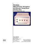
SBE 45 MicroTSG (RS-232) Reference Sheet
(see SBE 45 MicroTSG User’s Manual for complete details)
Sampling Modes
User-selectable modes include:
• Polled sampling – The MicroTSG takes one sample and sends the data to the computer. Polled sampling is useful for testing.
• Autonomous sampling – The MicroTSG samples data at pre-programmed intervals, defined by the Interval= command, and
sends the data to the computer. The MicroTSG does not enter quiescent (sleep) state between samples.
• Serial Line Sync - A pulse on the serial line causes the MicroTSG to wake up, take and output a single sample, and enter
quiescent (sleep) state automatically.
Communication Setup Parameters
1.
Double click on the Seaterm.exe.
2.
Once the main screen appears, in the Configure menu select the SBE 45 TSG. Input:
• Serial Port: COM1 through COM10 are available
• Baud Rate: 4800 (or other if applicable)
• Data Bits: 8
• Parity: No Parity
• Mode: RS-232 (full duplex)
3.
Send desired setup commands to the MicroTSG (see other side for a list of commands).
Note: See the Interface Box manual for operation of the MicroTSG with the Interface Box. The Interface Box can be added at any
time, and does not need to be part of the original MicroTSG order. The Interface Box must be placed in a mode to communicate
with the MicroTSG (Connect45 command) before you send commands through the Interface Box to the MicroTSG.
Deployment
1.
Verify setting of Power-Up Jumper J1 (see product configuration sheet on manual front cover for factory-setting):
• Autopower (default) – pins 1 and 2. The MicroTSG wakes up when power is applied.
• Normal – pins 2 and 3. The MicroTSG power up (wakes up) when there is a pulse on the serial lines. In this configuration,
the MicroTSG can be commanded into a quiescent (sleep) state with the QS command.
If the factory-setting listed on the product configuration sheet does not match your desired operation, see the manual for
procedures for accessing the PCB.
2.
Verify the AF24173 Anti-Foulant Device is installed.
3.
Mount MicroTSG on ship, with electrical connector at top, using four 1/4-inch bolt holes on sides. Provide clearance as follows:
• Bottom — 152 mm (6 inches) clearance for removal of the bottom plate, to allow access for replacing the anti-foul cylinder
and cleaning.
• Top — 305 mm (12 inches) clearance for removal of the top plate, to allow access for removing sensors and electronics.
• Sides — small clearance by using washers with the mounting hardware, to prevent binding when removing the top or
bottom plate.
4.
Install piping connections to MicroTSG’s 3/8-inch U.S. Standard NPT threads.
5.
Wiring to MicroTSG:
A. Install I/O cable connector, aligning long pin with small hole on MicroTSG I/O connector.
B. Tighten locking sleeve on I/O cable connector.
C. Connect I/O cable connector to computer serial port.
D. Connect I/O cable connector’s red and black wires to power supply (8-30 VDC).
Reference Sheet Version #008, 07-20-12; Firmware Version 1.1b
1
Command Instructions and List
•
•
•
•
Input commands in upper or lower case letters and register commands by pressing the Enter key.
If in quiescent (sleep) state, re-establish communications by pressing Connect on the Toolbar or the Enter key to get S> prompt.
If system does not return S> prompt after executing a command, press Enter key to get S> prompt.
MicroTSG sends ?CMD if invalid command is entered.
Shown below are the commands used most commonly in the field. See the Manual for a complete list and detailed descriptions.
CATEGORY
COMMAND
Status
DS
Baud=x
OutputFormat=x
OutputCond=x
Setup
OutputSal=x
OutputSV=x
SVAlgorithm=x
NCycles=x
QS
Interval=x
AutoOff=x
J1 jumper - Normal
Operating Mode
Interface PCB’s J1
jumper interacts with
these commands:
• Autopower
(default) –
pins 1 and 2
• Normal –
pins 2 and 3
AutoRun=N
SingleSample=Y or N
J1 jumper - Normal
AutoRun=Y
SingleSample=N
J1 jumper - Normal
AutoRun=Y
SingleSample=Y
J1 jumper - Autopower
AutoRun=N
SingleSample=Y or N
J1 jumper - Autopower
AutoRun=Y
SingleSample=N
J1 jumper - Autopower
AutoRun=Y
SingleSample=Y
Go
Sampling
Do not send if
MicroTSG is
sampling data at
pre-programmed
intervals.
Testing
Coefficients
Stop
TS
TSR
SLT
TH
SH
TT
TC
TTR
TCR
DC
DESCRIPTION
Display status.
x= baud rate (1200, 2400, 4800, 9600, 19200, 38400). Default 4800.
x=0 (default): Output order is temperature, conductivity, salinity, sound velocity.
x=1: Suppress space before conductivity output.
x=2: Reverse conductivity and salinity order (not for use with Seasave, SBE Data
Processing, or optional Interface Box).
x=Y (default): Output conductivity (S/m) with data.
x=N: Do not output conductivity with data.
x=Y: Output salinity (psu) with data.
x=N (default): Do not output salinity with data.
x=Y: Output sound velocity (m/sec) with data, calculated as defined by SVAlgorithm=.
x=N (default): Do not output sound velocity with data.
x=C (default): Calculate sound velocity as Chen and Millero.
x=W: Calculate sound velocity as Wilson.
x = number of A/D cycles to average (default=4).
Quit session and place MicroTSG in quiescent (sleep) state. Sampling stops. Applicable
only if Interface PCB J1 jumper in Normal position.
x = interval between samples (maximum 32767 seconds). Minimum time between samples
determined by NCycles, desired parameters (salinity, etc.), and baud rate.
(Functional only if J1 jumper in Normal position)
x=Y: Power-off (enter quiescent state) if 2 minutes have elapsed without receiving
command or sampling data.
x=N: Do not automatically power-off.
Wake up when Enter key pressed while in quiescent (sleep) state, wait for command.
Wake up when Enter key pressed while in quiescent (sleep) state, sample at rate specified by
Interval=. To stop sampling and get S> prompt, type Stop and press Enter key.
Wake up when Enter key pressed while in quiescent (sleep) state, take and output single
sample and automatically power-off. To wake up and get S> prompt, type Stop and press
Enter key.
Wake up when power applied, wait for a command.
Wake up when power applied, sample at rate specified by Interval= until power removed.
These are the required settings for running MicroTSG in 3-wire (power, ground, and
transmit) configuration or with a 90402 Interface Box.
Wake up when power applied, take and output a single sample. Wait for another command
until power removed.
Start sampling, as defined by SingleSample= and Interval=.
Applicable if AutoRun=N, or AutoRun=Y and you previously sent Stop to stop sampling.
Stop sampling data.
Take sample, hold converted data in RAM, output converted data
Take sample, hold raw data in RAM, output raw data.
Send converted data from last sample in RAM, then take new sample and hold converted
data in RAM.
Take sample, hold converted data in RAM.
Send held converted data from RAM.
Measure temperature for 100 samples or until Esc key is pressed, output converted data.
Measure conductivity for 100 samples or until Esc key is pressed, output converted data.
Measure temperature for 100 samples or until Esc key is pressed, output raw data.
Measure conductivity for 100 samples or until Esc key is pressed, output raw data.
Display calibration coefficients.
Reference Sheet Version #008, 07-20-12; Firmware Version 1.1b
2