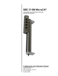
1
PN 90402 SBE 45 Power, Navigation, and Remote Temperature Interface Box For use with SBE 45 MicroTSG User’s Manual Sea-Bird Electronics, Inc. 13431 NE 20th Street Bellevue, Washington 98005 USA Telephone: 425-643-9866 Manual Version #009, 09/12/13 Fax: 425-643-9954 Firmware Version 2.0 and later E-mail: [email protected] Seasave V7 7.22.5 and later Website: www.seabird.com SBE Data Processing 7.22.5a and later Limited Liability Statement Extreme care should be exercised when using or servicing this equipment. It should be used or serviced only by personnel with knowledge of and training in the use and maintenance of oceanographic electronic equipment. SEA-BIRD ELECTRONICS, INC. disclaims all product liability risks arising from the use or servicing of this system. SEA-BIRD ELECTRONICS, INC. has no way of controlling the use of this equipment or of choosing the personnel to operate it, and therefore cannot take steps to comply with laws pertaining to product liability, including laws which impose a duty to warn the user of any dangers involved in operating this equipment. Therefore, acceptance of this system by the customer shall be conclusively deemed to include a covenant by the customer to defend, indemnify, and hold SEA-BIRD ELECTRONICS, INC. harmless from all product liability claims arising from the use or servicing of this system. 2 Manual revision 009 Declaration of Conformity Declaration of Conformity 3 SBE 45 Interface Box Manual revision 009 Table of Contents SBE 45 Interface Box Table of Contents Limited Liability Statement ................................................................ 2 Declaration of Conformity .................................................................. 3 Table of Contents ................................................................................. 4 Section 1: Introduction ........................................................................ 5 About this Manual .............................................................................................5 Unpacking Interface Box ...................................................................................6 Section 2: Interface Box Description .................................................. 7 System Description ............................................................................................7 Specifications .....................................................................................................8 System Communications ...................................................................................8 Connections, Switches, and LEDs .....................................................................9 Cables ..............................................................................................................10 Data Output Format .........................................................................................12 Section 3: Setting Up System............................................................. 13 Installing Software ...........................................................................................13 Communications Test and Setup......................................................................14 Commands .......................................................................................................17 Setting Up Instruments ....................................................................................20 Setting Up SBE 45 Configuration (.xmlcon or .con) File in Seasave ..............22 Section 4: Operating System ............................................................. 23 Acquiring Real-Time Data with Seasave .........................................................23 Processing Data with SBE Data Processing.....................................................24 Section 5: Routine Maintenance ....................................................... 25 Section 6: Troubleshooting................................................................ 26 Problem 1: Unable to Communicate with Interface Box .................................26 Problem 2: Unable to Communicate with SBE 45 through Interface Box.......26 Problem 3: Unable to Communicate with SBE 38 through Interface Box.......27 Problem 4: Unable to Communicate with NMEA Navigation Device through Interface Box .....................................................................................27 Problem 5: Nonsense or Unreasonable Data ....................................................27 Problem 6: Changing SBE 45 and/or SBE 38 Baud Rate without Cables for Direct Connection.............................................................28 Glossary .............................................................................................. 29 Safety and Electrical Symbols .........................................................................29 Appendix I: NMEA Data................................................................... 30 NMEA Raw Message Formats ........................................................................30 Troubleshooting NMEA ..................................................................................31 Problem 1: Yellow NMEA LED Not Flashing ..........................................31 Problem 2: Yellow NMEA LED Flashing, but Lat/Lon Data Not Displaying .............................................................31 NMEA Simulation Program ............................................................................32 Appendix II: Replacement Parts ...................................................... 34 Appendix III: Manual Revision History .......................................... 35 Index .................................................................................................... 36 4 Manual revision 009 Section 1: Introduction SBE 45 Interface Box Section 1: Introduction This section includes photos of a standard PN 90402 – SBE 45 Power, Navigation, and Remote Temperature Interface Box shipment. About this Manual This manual is to be used with the PN 90402 – SBE 45 Power, Navigation, and Remote Temperature Interface Box for the SBE 45 MicroTSG. It is organized to guide the user from installation through operation. We have included specifications, setup and operation descriptions, and helpful notes throughout the manual. Sea-Bird welcomes suggestions for new features and enhancements of our products and/or documentation. Please contact us with any comments or suggestions ([email protected] or 425-643-9866). Our business hours are Monday through Friday, 0800 to 1700 Pacific Standard Time (1600 to 0100 Universal Time) in winter and 0800 to 1700 Pacific Daylight Time (1500 to 0000 Universal Time) the rest of the year. 5 Manual revision 009 Section 1: Introduction SBE 45 Interface Box Unpacking Interface Box Shown below is a typical PN 90402 – SBE 45 Power, Navigation, and Remote Temperature Interface Box shipment. Interface Box DC power connector Cable SBE 45 to Interface Box AC power cable Connectors for SBE 45, SBE 38, and NMEA (3 connectors/Interface Box) I/O cable (Interface Box to computer) Navigation Interface test cable (Interface Box to NMEA navigation device simulation computer) (optional) Cable SBE 38 to Interface Box PN 90402 SBE 45 Power, Navigation, and Remote Temperature Interface Box For use with SBE 45 MicroTSG Interface Box Manual 6 Software, and Electronic Copies of Software Manuals and User Manual Manual revision 009 Section 2: Interface Box Description SBE 45 Interface Box Section 2: Interface Box Description This section describes the functions and features of the Interface Box, system communications, and output data format. System Description The PN 90402 – SBE 45 Power, Navigation, and Remote Temperature Interface Box provides continuous power and an opto-isolated RS-232C interface for the SBE 45 MicroTSG Thermosalinograph. Additionally, the Interface Box provides: • An opto-isolated NMEA receiver for an optional NMEA navigation device (not supplied by Sea-Bird) • Power and an RS-232C interface for an optional SBE 38 remote temperature sensor Baud rates between the Interface Box and SBE 45, SBE 38, NMEA navigation device, and computer are user-programmable. Notes: • Help files provide detailed information on software use. • NMEATest, a NMEA navigation device simulation program, is part of the SBE Data Processing installation. • Separate software manuals on CDROM contain detailed information on the setup and use of Seasave V7 and SBE Data Processing. The Interface Box merges position data and SBE 38 remote temperature data with SBE 45 data. The NMEA Interface decodes messages that are output from navigation devices supporting NMEA 0183 protocol, outputting data in GGA, GLL, RMA, RMC, or TRF format. Decoded Latitude, Longitude, date, and time and SBE 38 temperature data are appended to the SBE 45 data stream in the Interface Box. The data, in ASCII engineering units, is passed to the computer for storage and/or display. The Interface Box can be AC- or DC-powered: • AC power - universal 85-265 VAC input with frequency of 47-63 Hz • DC power - 10-28 VDC input. The Interface Box is supplied with a powerful Win 2000/XP software package, Seasoft V2, which includes: • Seaterm – terminal program for easy setup. • Seasave V7 – program for acquiring, converting, and displaying real-time or archived raw data. • SBE Data Processing – program for calculation and plotting of conductivity, temperature, pressure, auxiliary sensor data, and derived variables such as salinity and sound velocity. 7 Manual revision 009 Section 2: Interface Box Description SBE 45 Interface Box Specifications Power Requirements AC: 100-240 VAC / 47-63Hz / 0.25A, The Interface Box should always be used with a threeterminal outlet that includes a protective earth. or DC: 10-28 VDC / 0.10A Fuse 5x20mm, 250VAC Slow-Blow, 0.5 Amp Operating Current Interface Box alone: 27 mA Interface Box with SBE 45: 65 mA Interface Box with SBE 45 and 38: 80 mA Dimensions 200 x 121 x 76 mm (7.875 x 4.75 x 3 inch) Weight 1.1 kg (2.5 lbs) Installation Environment Interface Box operates properly under the following conditions: • Indoor use • Altitude up to 2000 meters • Temperature from 5 °C to 40 °C • Maximum relative humidity 80%, non-condensing • Mains supply voltage ±10% System Communications 8 Manual revision 009 Section 2: Interface Box Description SBE 45 Interface Box Connections, Switches, and LEDs Communications with and power to SBE 45 Communications with and power to SBE 38 DC Input AC input To computer Output from NMEA device Note: See Cables below for wiring diagrams. Ventilation Connections: Cables longer than 3 meters should be installed inside an earthed metal conduit by a qualified electrician. This minimizes the potential for external signals to disrupt communication and ensures that high voltage lines (such as the sea cable) are sufficiently protected. Cables shorter than 3 meters can be used without shielding when installing or bench testing the instrument. • SBE 45 - to SBE 45 MicroTSG; use supplied 4-pin MS-3106A-14S-2P connector or supplied cable: • • Interface Box Pin A Pin B Pin C Pin D Function Common RS-232 data transmit to SBE 45 RS-232 data receive from SBE 45 Power to SBE 45 NMEA - to NMEA navigation device; use supplied 2-pin MS-3106A12S-3S connector or supplied test cable: Interface Box Pin A Pin B Function NMEA A (signal) NMEA B (signal return) Interface Box Pin A Pin B Pin C Pin D Function Common RS-232 data transmit to SBE 38 RS-232 data receive from SBE 38 Power to SBE 38 Interface Box Pin 2 Pin 3 Pin 5 Function RS-232 data transmit to computer RS-232 data receive from computer Ground SBE 38 - to SBE 38 remote temperature sensor; use supplied 4-pin MS-3106A-14S-2P connector or optional cable: • Serial - to computer with supplied DB-9P/DB-9S cable. • AC Input - to standard, 3-prong, grounded, VAC power supply, using the supplied UL/IED-approved power cord, or DC Input - to VDC power supply. Power Switch and Red LED: Switch turns power to Interface Box on/off. Red LED turns on to indicate power is on. LEDs: Indicate if Interface Box is communicating with other parts of system: LED: Yellow SBE 45 Yellow SBE 38 Yellow NMEA Green PC 9 Flashes when carriage return (decimal 13) received from: SBE 45 SBE 38 NMEA navigation device Computer Manual revision 009 Section 2: Interface Box Description Cables MS3106 to MCIL4MP cable – SBE 45 connector on Interface Box to SBE 45 PN 171887 DB9 to DB9 cable – Serial connector on Interface Box to computer 10 SBE 45 Interface Box Manual revision 009 Section 2: Interface Box Description SBE 45 Interface Box DC Input Cable – DN 32398 DC connector on Interface Box to power source NMEA Test Cable (NMEA Input connector on Interface Box) – Drawing 32786 2-pin to DB9 test cable – NMEA connector on Interface Box to computer MS3106 to RMG-4FS cable – SBE 38 connector on Interface Box to SBE 38 11 Manual revision 009 Section 2: Interface Box Description SBE 45 Interface Box Data Output Format The time between each output scan is governed by the SBE 45’s setup. The Interface Box outputs the most recent data from the SBE 38 and/or NMEA navigation device with each scan of SBE 45 data. The Interface Box outputs data in the following format and order: Format=0 (standard format) Notes: • Inclusion of all parameters except for t1 (temperature from SBE 45) is dependent on configuration – if the system does not include the specified instrument or the parameter is not enabled, the corresponding data is not included in the output data stream, shortening the data string. • Not all NMEA navigation devices transmit time and / or date. • The SBE 45 must be set up to output data with OutputFormat=0 or 1 (SBE 45 OutputFormat=2 is not compatible with the Interface Box). Note: When using Format=1: • Set up the SBE 45 with: OutputFormat=0 or 1, OutputSV=Y, and OutputCond=Y and/or OutputSal=Y and connect an SBE 38 to the Interface Box. • The Interface Box will not output any parameters other than what is shown at right, regardless of settings in the SBE 45 or connection of the Interface Box to a NMEA navigation device. • Format=1 is not compatible with Seasave real-time data acquisition software or SBE Data Processing post-processing software. t1=ttt.tttt, c1=cc.ccccc, s = sss.ssss, sv=vvvv.vvv, t2 = ttt.tttt, lat = DD MM.MMMM W, lon = DDD MM.MMMM W, hms = HHMMSS, dmy = DDMMYY where • t1 = temperature from SBE 45 (°C, ITS-90). • c1 = conductivity from SBE 45 (S/m); output if OutputCond=Y in SBE 45. • s = salinity (psu) calculated from t1 and c1 by SBE 45; output if OutputSal=Y in SBE 45. • sv = sound velocity (m/sec); output if OutputSV=Y in SBE 45. If the Interface Box is acquiring data from an SBE 38 remote temperature sensor and if the SBE 45 is set to OutputCond=Y or OutputSal=Y: the Interface Box recalculates sound velocity based on s (or t1 and c1) from the SBE 45 and temperature t2 from the SBE 38. This provides the most accurate sound velocity results, because sound velocity is a function of salinity and temperature, and the SBE 38 typically provides more accurate sea surface temperature than the thermosalinograph, since it is closer to the seawater intake. Otherwise: the Interface Box outputs sound velocity calculated from t1 and c1 by the SBE 45. • t2 = temperature from SBE 38 (°C, ITS-90 if Format=C in SBE 38; number of digits after decimal point is set with Digits= in SBE 38). • lat = latitude from NMEA navigation device. DD = degrees. MM.MMMM = minutes and fractions of minutes; number of digits after decimal point is number of digits in received NMEA string. W = N (north) or S (south). • lon = longitude from NMEA navigation device. DDD = degrees. MM.MMMM = minutes and fractions of minutes; number of digits after decimal point is number of digits in received NMEA string. W = E (east) or W (west). • hms = time from NMEA navigation device (hour, minute, second). • dmy = date from NMEA navigation device (day, month, year). All data is separated with a comma and a space. Each scan ends with a carriage return <CR> and line feed <LF>. Leading zeros are suppressed, except for one zero to the left of the decimal point. Format=1 (custom format for interfacing with a Kongsberg EM 300 Multibeam Echo Sounder) tt.ttt vvvv.v where • tt.ttt = temperature from SBE 38 remote temperature sensor (°C, ITS-90). • vvvv.v = sound velocity (m/sec) calculated in Interface Box from: salinity based on conductivity and temperature measured by SBE 45, and temperature measured by SBE 38 remote temperature sensor Temperature and sound velocity data is separated with a space. Each scan ends with a carriage return <CR> and line feed <LF>. Leading zeros are suppressed, except for one zero to the left of the decimal point. 12 Manual revision 009 Section 3: Setting Up System SBE 45 Interface Box Section 3: Setting Up System This section covers: • Installing Sea-Bird software • Communications testing and setup • System commands • Setting up the SBE 45 configuration (.xmlcon or .con) file Installing Software Notes: • Help files provide detailed information on the software. • NMEATest, a NMEA navigation device simulation program, is part of the SBE Data Processing installation. • Separate software manuals on CDROM contain detailed information on the setup and use of Seasave V7 and SBE Data Processing. • Sea-Bird supplies the current version of our software when you purchase an instrument. As software revisions occur, we post the revised software on our FTP site. See our website (www.seabird.com) for the latest software version number, a description of the software changes, and instructions for downloading the software from the FTP site. Sea-Bird recommends the following minimum system requirements for Seasoft V2: Windows 2000 or later, 500 MHz processor, 256 MB RAM, and 90 MB free disk space for installation. Although Seasoft V2 was designed to work with a PC running Win 2000/XP; extensive testing has not shown any compatibility problems when using the software with a PC running Windows Vista. If not already installed, install Sea-Bird software on your computer using the supplied software CD. 1. Insert the CD in your CD drive. 2. Install software: Double click on SeasoftV2_date.exe (date is the date that version of the software was created). Follow the dialog box directions to install the software. The installation program allows you to install the desired components. Install all the components, or just install Seaterm (terminal program), Seasave V7 (real-time data acquisition), and SBE Data Processing (data processing). The default location for the software is c:\Program Files\Sea-Bird. Within that folder is a sub-directory for each program. 13 Manual revision 009 Section 3: Setting Up System SBE 45 Interface Box Communications Test and Setup Notes: • See Seaterm’s Help files. • The Interface Box is not available in the list of instrument types. Select SBE 45 as the instrument type. 1. With power to the Interface Box off, double click on SeaTerm.exe. If this is the first time Seaterm is used, the setup dialog box may appear: SBE 45 Select the instrument type (SBE 45 TSG) and the computer COM port for communication with the Interface Box. Click OK. 2. The main screen looks like this: Menus Toolbar Command/Data Echo Area Status bar Note: There is at least one way, and as many as three ways, to enter a command: • Manually type a command in Command/Data Echo Area • Use a menu to automatically generate a command • Use a Toolbar button to automatically generate a command Note: Once the system is configured and connected (Steps 3 and 4 below), to update the Status bar: • on the Toolbar, click Status; or • from the Utilities menu, select Instrument Status. Seaterm sends the status command, which displays in the Command/Data Echo Area, and updates the Status bar. Computer COM port Instrument Instrument EPROM version • • • • Capture to file status – grayed out if not capturing Baud rate, data bits, stop bits, and parity Menus – Contains tasks and frequently executed instrument commands. Toolbar – Contains buttons for frequently executed tasks and instrument commands. All tasks and commands accessed through the Toolbar are also available in the Menus. To display or hide the Toolbar, select View Toolbar in the View menu. Grayed out Toolbar buttons are not applicable. Command/Data Echo Area – Echoes a command executed using a Menu or Toolbar button, as well as the instrument’s response. Additionally, a command can be manually typed in this area, from the available commands for the instrument. Status bar – Provides status information. To display or hide the Status bar, select View Status bar in the View menu. 14 Manual revision 009 Section 3: Setting Up System SBE 45 Interface Box Following are the Toolbar keys applicable to the Interface Box: Toolbar Keys Equivalent Command* Re-establish communications with Interface Box. (press Enter Connect Computer responds with S> prompt. key) Status Display instrument status. DS Capture instrument responses on screen to file. Interface Box has no internal memory; you must capture before sampling begins to save data Capture — for future review and processing, or use Seasave for data acquisition. File has .cap extension. Press Capture again to turn off capture. Capture status displays in Status bar. Free computer COM port used to communicate Disconnect with Interface Box. COM port can then be used — by another program. *See Command Descriptions. Note: The Interface Box is not available in the list of instrument types. Select SBE 45 as the instrument type. 3. Description In the Configure menu, select SBE 45 TSG. The dialog box looks like this: Interface for communication between computer and Interface Box. Select RS-232. Computer COM port, baud rate, data bits, and parity for communication between computer and Interface Box. Select 4800, 9600, or 19200 baud (set this greater than baud rate you will use to communicate between Interface Box and SBE 45, SBE 38, and NMEA navigation device). Notes: • Seaterm’s baud rate must be the same as the Interface Box baud rate (set with PCBaud=). Baud is factoryset to 9600, but can be changed by the user (see Commands). • When you click OK, Seaterm saves the Configuration Options settings to the SeaTerm.ini file in your Windows directory. SeaTerm.ini contains the last saved settings for each instrument (SBE 37, 45, etc.). When you open Seaterm and select the desired instrument in the Configure menu, the Configuration Options dialog box shows the last saved settings for that instrument. Make the selections in the Configuration Options dialog box. Click OK to save the settings. 4. Turn on power to the Interface Box. The display looks like this (if the Interface Box is set up to power-up in Normal mode with the IMode=NORMAL command; see Commands for details): SBE45 Junction Box V 1.4 mode is normal If the system does not respond as described: • Click Connect on the Toolbar to attempt to establish communications. • Verify the SBE 45 was selected in the Configure menu and settings were entered correctly in the Configuration Options dialog box. • Check cabling between the computer and the Interface Box. • If the response shows mode is connect45, the Interface Box is set up to power-up in SBE 45 mode (IMode=CONNECT45). Type @ to return to Normal mode for communication with the Interface Box. 15 Manual revision 009 Section 3: Setting Up System SBE 45 Interface Box 5. If the SBE 45 was set to AutoRun=Y and its J1 jumper was set to pins 1 and 2 (begin sampling automatically on power up), data from the Interface Box begins scrolling on the screen. Each time data is received from an instrument (SBE 45, SBE 38, and NMEA navigation device), the corresponding LED on the Interface Box flashes. If data is not received, is incorrect, or is not updating properly for some or all instruments: • Verify that the instrument is connected to the Interface Box and that the proper cable is used. • Check the baud rate of each instrument (SBE 45, SBE 38, and NMEA navigation device). These baud rates must be less than the baud rate for communication between the Interface Box and the computer. If necessary, connect each instrument directly to the computer and use Seaterm to reset its baud rate. See the appropriate instrument manual for details. • Check that the setup of each instrument is compatible with operation with the Interface Box. See Setting Up Instruments. • If data is not received from a NMEA navigation device, see Appendix I: NMEA Data for troubleshooting information. 6. If desired, type Stop and press the Enter key to stop the scrolling data. Note that you can send commands to the Interface Box and/or attached instruments while it is transmitting data, but it easier to see what the commands and responses are without the scrolling data. 7. Display Interface Box status information by clicking Status on the Toolbar. The display looks like this: Note: The Interface Box outputs data at the SBE 45’s data output rate. If the SBE 45 is not outputting any data, data from the SBE 38 and/or NMEA navigation device will not appear at all. SBE45 Junction Box V 1.4 SBE 45 baud rate = 4800 SBE 38 baud rate = 4800 NMEA baud rate = 4800 standard output format Note that the baud rates shown must be less than the baud rate for communication between the Interface Box and the computer. Note: You must restart SBE 45 and SBE 38 sampling using Go before returning to Normal mode, or these instruments will not transmit their data to the Interface Box. 8. Verify SBE 45 setup by putting the Interface Box in SBE 45 mode: A. Type Connect45 and press the Enter key. If the SBE 45 is set for AutoPower=Y and SingleSample=N, SBE 45 data will scroll across the screen. Type Stop and press the Enter key to stop the scrolling data. B. Send desired setup commands to the SBE 45 (see Setting Up Instruments for required setup parameters). C. Type GO and press the Enter key to restart SBE 45 sampling. SBE 45 data should begin scrolling on the screen. D. Type @ to return to Normal mode for communication with the Interface Box. 9. Verify SBE 38 setup by putting the Interface Box in SBE 38 mode: A. Type Connect38 and press the Enter key. If the SBE 38 is set for AutoPower=Y, SBE 38 data will scroll across the screen. Type Stop and press the Enter key to stop the scrolling data. B. Send desired setup commands to the SBE 38 (see Setting Up Instruments for required setup parameters). C. Type Go and press the Enter key to restart SBE 38 sampling. SBE 38 data should begin scrolling on the screen. D. Type @ to return to Normal mode for communication with the Interface Box. 10. Type Start and press the Enter key to restart data transmission through the Interface Box. The system is ready for deployment. 16 Manual revision 009 Section 3: Setting Up System SBE 45 Interface Box Commands This section describes commands and provides sample outputs. When entering commands: • Input commands to the Interface Box in upper or lower case letters and register commands by pressing the Enter key. • The Interface Box sends ? if an invalid command is entered. • If the system does not return an S> prompt after executing a command, press the Enter key to get the S> prompt. • The Interface Box can accept commands while transmitting data. Type in any command and press the Enter key; the S> is not required. Status Command DS Display firmware version and baud rate settings. Equivalent to Status button on Toolbar. List includes, where applicable, command used to modify parameter. • firmware version • SBE 45 baud rate [45Baud=] • SBE 38 baud rate [38Baud=] • NMEA baud rate [NMEABaud=] • output format [Format=] – standard output format or output format 1 Example: (user input shown in bold) S>DS SBE45 Junction Box V 1.4 SBE 45 baud rate = 4800 SBE 38 baud rate = 4800 NMEA baud rate = 4800 standard output format [45Baud=] [38Baud=] [NMEABaud=] [Format=] Baud Rate Commands Note: Baud rate for communication between Interface Box and computer must be greater than baud between Interface Box and SBE 45, SBE 38, and NMEA navigation device. PCBaud=x x= baud rate for communication between Interface Box and computer (4800, 9600, or 19200). Default 9600. 45Baud=x x= baud rate for communication between Interface Box and SBE 45 (1200, 2400, 4800, or 9600). Default 4800. Must match baud set in SBE 45 with Baud=. 38Baud=x x= baud rate for communication between Interface Box and optional SBE 38 (1200, 2400, 4800, or 9600). Default 4800. Must match baud set in SBE 38 with Baud=. NMEABaud=x x= baud rate for communication between Interface Box and optional NMEA navigation device (4800 or 9600). Default 4800. Must match baud of NMEA navigation device. 17 Manual revision 009 Section 3: Setting Up System SBE 45 Interface Box Mode Commands IMode=x x=Normal: On power-up, Interface Box is in Normal mode for communicating with Interface Box. Notes: • IMode=Connect45 is not compatible with Seasave real-time data acquisition software. • Type @ or press the Esc key to exit SBE 45, SBE 38, or NMEA mode and return to Normal mode for communicating with the Interface Box. x=Connect45: On power-up, Interface Box is in SBE 45 mode, for communicating with SBE 45 through Interface Box. Equivalent to powering up in Normal mode, and then immediately sending Connect45. When you send IMode=Connect45, Interface Box is also immediately placed in SBE 45 mode. Example: (user input shown in bold) With the Interface Box in Normal mode, turn power on. Interface Box responds as follows: S>SBE 45 Junction Box V 1.4 mode is normal S>IMODE=CONNECT45 (send command to change start-up mode; also switches to SBE 45 mode now) Connected to SBE 45, press @ or Esc to return to normal mode S>DS (transmitted to SBE 45, so status response is from SBE 45) SBE45 V 1.1 SERIAL NO. 0059 . . . . (see SBE 45 manual for remainder of SBE 45 status response) S> (send other commands to SBE 45 as desired) @ (put Interface Box back in normal mode) mode switched back to normal S>DS (transmitted to Interface Box, so status response is from Box) SBE45 Junction Box V 1.4 . . . . (see above for remainder of Interface Box status response) Turn power off and then on again. Interface Box starts up in SBE 45 mode: S>SBE 45 Junction Box V 1.4 Mode is connect 45 SBE45 V 1.1 S> (send commands to SBE 45 as desired) Connect45 Put Interface Box in SBE 45 mode, allowing you to send commands to SBE 45 through Interface Box. Example: (user input shown in bold) S>CONNECT45 Connected to SBE 45, press @ or Esc to return to normal mode S>DS (transmitted to SBE 45, so status response is from SBE 45) SBE45 V 1.1 SERIAL NO. 0059 . . . . (see SBE 45 manual for remainder of SBE 45 status response) S>OUTPUTSV=N (do not output sound velocity from SBE 45) @ mode switched back to normal S>DS (transmitted to Interface Box, so status response is from Interface Box) SBE45 Junction Box V 1.4 . . . . (see above for remainder of Interface Box status response) Connect38 Put Interface Box in SBE 38 mode, allowing you to send commands to SBE 38 through Interface Box. ConnectNMEA Put Interface Box in NMEA mode, allowing you to look at data as transmitted by NMEA navigation device. 18 Manual revision 009 Section 3: Setting Up System SBE 45 Interface Box Output Format Command Note: See Data Output Format in Section 2: Interface Box Description for details. • Format=1 is not compatible with Seasave real-time data acquisition software or SBE Data Processing post-processing software. Format=x x=0: Output standard format (default) t1=ttt.tttt, c1=cc.ccccc, s = sss.ssss, sv=vvvv.vvv, t2 = ttt.tttt, lat = DD MM.MMMM W, lon = DDD MM.MMMM W, hms = HHMMSS, dmy = DDMMYY x=1: Output custom format for Kongsberg EM 300 Multibeam Echo Sounder tt.ttt vvvv.v Note: Interface Box starts transmitting data automatically when power is turned on and stops when power is removed. Use Stop to stop transmitting data temporarily while setting up the instruments, and then restart transmitting data by sending Start. Sampling Commands Start Start transmitting data. Stop Stop transmitting data. Diagnostic Command *EETest Test EEPROM; reset baud rates to defaults (new bauds take effect on next power up). Example: (user input shown in bold) S>*eetest wr: 128 . . wr: 1920 rd: 256 . . rd: 1792 passed EEprom test S> 19 Manual revision 009 Section 3: Setting Up System SBE 45 Interface Box Setting Up Instruments Notes: • In Seaterm, use the @ character or press the Esc key to exit SBE 45 mode, SBE 38 mode, or NMEA mode and return to Normal mode for communicating with the Interface Box. • If you reset the baud rate, you may need to turn power off and then on again to resume communications at the new baud rate. • SBE 45 OutputFormat=2 is not compatible with the Interface Box. SBE 45 Set the SBE 45 J1 jumper to Autopower (pins 1 and 2) for use with the Interface Box (this is the default setting when the SBE 45 is shipped). With the SBE 45 directly connected to the computer, set the SBE 45 baud rate with Baud= to match the baud rate set in the Interface Box with 45Baud=. The remaining setup can be performed with the SBE 45 directly connected to the computer, or through the Interface Box. With the Interface Box connected to the computer and SBE 45, send Connect45 to the Interface Box to put the Interface Box in SBE 45 mode and send commands to the SBE 45 through the Interface Box. • Set up the SBE 45 to begin sampling when power is applied by sending AutoRun=Y and SingleSample=N. • Set up the SBE 45 to output data in the following order: temperature, conductivity, salinity, and sound velocity by sending OutputFormat=0 or OutputFormat=1. Note: The SBE 45 always outputs temperature. Conductivity is output if OutputCond=Y, salinity is output if OutputSal=Y, and sound velocity is output if OutputSal=Y. • Set the other sampling and output parameters for the SBE 45 as desired (see the SBE 45 manual). SBE 38 With the SBE 38 directly connected to the computer: • Set the SBE 38 baud rate with Baud= to match the baud rate set in the Interface Box with 38Baud=. • Set up the SBE 38 to communicate using RS-232 with Interface=232. The remaining setup can be performed with the SBE 38 directly connected to the computer, or through the Interface Box. With the Interface Box connected to the computer, SBE 45, and SBE 38, send Connect38 to the Interface Box to put the Interface Box in SBE 38 mode and send commands to the SBE 38 through the Interface Box. • Set up the SBE 38 to begin sampling when power is applied by sending AutoRun=Y. • Set the output format and number of digits with Format= and Digits=. You must set the format to converted data (Format=C) if you will process the data with SBE Data Processing. • Set the other sampling parameters for the SBE 38 as desired (see the SBE 38 manual). 20 Manual revision 009 Section 3: Setting Up System SBE 45 Interface Box NMEA Navigation Device The Interface Box is designed to decode messages that are output from navigation devices supporting NMEA 0183 protocol, outputting messages in GGA, GLL, RMA, RMC, or TRF format. Verify that the navigation device baud rate matches the baud rate set in the Interface Box with NMEABaud= (4800 or 9600). Note: Not all NMEA navigation devices transmit time and / or date. The most recent decoded Latitude, Longitude, time, and date data is appended to the end of the SBE 45 data stream in the Interface Box and passed to the computer for storage and/or display with the SBE 45 data. Position data format is detailed in Appendix I: NMEA Data. The Yellow NMEA LED on the Interface Box flashes each time a NMEA message is received (should be the same rate at which your navigation device is transmitting). Example 1: SBE 45 is set up to output data once every 10 seconds. A navigation device outputs its NMEA message once every 5 seconds. The Yellow NMEA LED flashes every 5 seconds. However, only the most recent NMEA message is appended to each scan of SBE 45 data. Example 2: SBE 45 is set up to output data once every 1 second. A navigation device outputs its NMEA message once every 5 seconds, and the Yellow NMEA LED flashes every 5 seconds. The same message is appended to each scan of SBE 45 data within that 5 seconds. While communicating with the Interface Box, send the ConnectNMEA command to view the raw NMEA data. 21 Manual revision 009 Section 3: Setting Up System SBE 45 Interface Box Setting Up SBE 45 Configuration (.xmlcon or .con) File in Seasave Notes: • Seasave and SBE Data Processing versions 7.20a introduced .xmlcon files (in XML format). Versions 7.20a and later allow you to open a .con or .xmlcon file, and to save it to a .con or .xmlcon file. Seasave and SBE Data Processing use the same file. • A new or recalibrated CTD ships with a configuration file that reflects the current configuration as we know it. The file is named with the instrument serial number, followed by a .con extension. For example, for a CTD with serial number 2375, Sea-Bird names the file 2375.con. You may rename the file (but not the extension) if desired; this will not affect the results. The Interface Box integrates optional NMEA navigation device data and optional SBE 38 data into the SBE 45 data stream. Seasave, Sea-Bird’s realtime data acquisition and display program, stores and displays this data along with the SBE 45 data. Seasave requires a configuration file, which defines the SBE 45 – which parameters are output by the SBE 45, and the data output rate - and indicates whether NMEA and SBE 38 data is to be appended to the data stream. Seasave (as well as our data processing software) uses the information in the configuration file to interpret and process the data. If the configuration file does not match the actual instrument configuration, the software will not be able to interpret and process the data correctly. To verify the contents of the .xmlcon or .con configuration file: 1. Double click on Seasave.exe. 2. Click Configure Inputs. On the Instrument Configuration tab, click Open. In the dialog box, select the .xmlcon or .con file and click Open. 3. The configuration information appears on the Instrument Configuration tab. Verify that the outputs match those programmed into your SBE 45, and that the use of the Interface Box, and addition of remote temperature and NMEA, are correct. Click Modify to bring up a dialog box (shown below) to change the configuration. Time between scans. Must agree with SBE 45 setup (Interval=); see reply from DS. Define data in SBE 45 data stream: • Output conductivity with each scan - Must agree with SBE 45 setup (OutputCond=). • Output salinity with each scan – Must agree with SBE 45 setup (OutputSal=). • Output sound velocity with each scan – Must agree with SBE 45 setup (OutputSV=). See reply from DS for setup programmed into SBE 45. New to create new .xmlcon or .con file for this CTD. Open to select different .xmlcon or .con file. Save or Save As to save current .xmlcon or .con file settings. • Use junction box - Select if SBE 45 data transmitted to computer through Interface Box. • SBE 38 temperature added – Select if Interface Box connected to SBE 38 remote temperature sensor. If selected, Seasave and SBE Data Processing (Data Conversion and Derive modules) use remote temperature data when calculating density and sound velocity. • NMEA data added - Select if Interface Box connected to a NMEA navigation device. Seasave automatically adds current latitude, longitude, and universal time code to data header. Select NMEA (Lat/Lon) Interface in Seasave’s Configure menu to control how Lat/Lon data is incorporated. 4. Click Save or Save As to save any changes to the .xmlcon or .con file. Click Exit when done reviewing / modifying the configuration. 22 Manual revision 009 Section 4: Operating System SBE 45 Interface Box Section 4: Operating System Note: For acquiring data in Seasave: • SBE 45 must be set up for autonomous sampling (SingleSample=N, AutoRun=Y, and J1 jumper in Autopower position – pins 1 and 2), and with OutputFormat=0 or 1. See Section 3: Setting Up System. • Interface Box must be set up with Format=0 (standard format) and IMode=NORMAL (Normal mode). This section covers acquiring real-time data with Seasave and processing data with SBE Data Processing. • Seasave saves the data in the format (data format and header) required by SBE Data Processing. If you use other software to acquire data, the data will not be in the format required by SBE Data Processing. See Connections, Switches, and LEDs in Section 2: Interface Box Description for wiring details. Acquiring Real-Time Data with Seasave Notes: • If the system includes an SBE 38 remote temperature sensor, Seasave uses the remote temperature data when calculating density and sound velocity. • The baud between the Interface Box and computer (defined in Configure Inputs, on the serial Ports tab) must agree with the baud programmed into the Box with PCBaud=. 1. Turn on power to the Interface Box. The SBE 45 will start sampling and transmitting data to the Interface Box. Data will not appear in Seasave until you tell Seasave to start real-time data acquisition below. 2. Double click on Seasave.exe. 3. Perform any desired setup in the Configure Inputs, Configure Outputs, and Display menus. 4. In the Real-Time Data menu, select Start. The dialog box looks like this: Data Archiving Options: • Begin archiving data immediately to store raw (frequencies, A/D counts, and/or voltages) real-time data as soon as Start button is clicked and communication is established. • Begin archiving data when ‘Start Archiving’ command is sent to control when data begins to be written to file. If you make this selection, when you click Start button and communication is established, a dialog box with Start Archiving button appears. Click this button when ready to begin saving scans to file, or select Start Archiving in Real-Time Data menu. • Do not archive data for this cast to not save data to a file. Real-time data will still appear in displays. Configuration Options: Currently selected instrument configuration (.xmlcon or .con) file is shown, containing information on which parameters are output by SBE 45, SBE 45 data output rate, and whether NMEA and SBE 38 data are appended to data stream. To modify input configuration (.xmlcon or .con file, serial port, water sampler, TCP/IP ports, and/or miscellaneous), click Configure Inputs. To modify outputs (serial data output, shared file output, mark variables, TCP/IP output, TCP/IP ports, SBE 14 remote display, PC alarms, header form and/or diagnostics), click Configure Outputs. • Timeout in seconds at startup: Time allowed before first data scan is received from instrument. Seasave will time out and stop attempting to acquire data if data is not received from instrument within this time period. • Timeout in seconds between scans: Maximum gap allowed between scans after first data scan is received from instrument. Seasave will time out and stop attempting to acquire data if data is not received from instrument within this time period, Seasave stops attempting to acquire data after this gap). 23 Click Select Output Data File Name. Save Archived Data As dialog box appears; browse to desired file location, enter desired file name, and click Save. Manual revision 009 Section 4: Operating System 5. SBE 45 Interface Box In the Start Real-Time Data Acquisition dialog box, click Start. A. If you selected Begin archiving data immediately or Begin archiving data when ‘Start Archiving’ command is sent above, and selected Prompt for Header Information in the Header Form setup (Configure Outputs), the Header Information dialog box appears. Fill in the desired header and click OK. B. If you selected Check Scan Length in the Options menu, Seasave checks the configuration (.xmlcon or .con) file to verify that the scan length defined by the configuration file matches the SBE 45 (i.e., number of outputs and inclusion of NMEA is as defined in the configuration file). If a Scan length error appears, verify that: • You are using the correct .xmlcon or .con file. • The .xmlcon or .con file has been updated as necessary if you added or deleted the SBE 38, added or deleted NMEA, etc. C. Seasave sends a message: Waiting for data . . .. Seasave will time out if data is not received within Timeout in seconds at startup. D. Real-time data then starts appearing in the screen display(s). 6. To stop real-time data acquisition: In the Real-Time Data menu, select Stop. 7. Stop the SBE 45 sampling by turning off power to the Interface Box. Processing Data with SBE Data Processing Note: See the SBE Data Processing manual and/or Help files. 1. Convert the .hex data file created by Seasave to a .cnv file in SBE Data Processing’s Data Conversion module. 2. Once the data is converted, it can be further processed and plotted in SBE Data Processing’s other modules. Note that if the data stream includes SBE 38 remote temperature data, SBE Data Processing’s Data Conversion and Derive modules use the remote temperature data when calculating density and sound velocity. 24 Manual revision 009 Section 5: Routine Maintenance SBE 45 Interface Box Section 5: Routine Maintenance To clean the Interface Box: 1. Disconnect the power and any other cables from the Interface Box. 2. Using a soft cotton cloth dampened with warm water, clean the exterior of the Interface Box with gentle pressure. Use special care cleaning around any connectors, to avoid getting water into them. 3. Wait until the Interface Box is completely dry before reconnecting power cables and other electrical connections. 25 Manual revision 009 Section 6: Troubleshooting SBE 45 Interface Box Section 6: Troubleshooting This section reviews common problems in operating the Interface Box, and provides the most likely causes and solutions. Problem 1: Unable to Communicate with Interface Box The Interface Box message prompt indicates that communications between the Interface Box and computer have been established. Before proceeding with troubleshooting, attempt to establish communications again by clicking the Connect button on Seaterm’s toolbar or hitting the Enter key several times. Cause/Solution 1: The I/O cable connection may be loose. Check the cabling between the Interface Box and computer for a loose connection. Cause/Solution 2: The instrument type and/or its communication settings may not have been entered correctly in Seaterm. Select SBE 45 in the Configure menu and verify the settings in the Configuration Options dialog box. The settings should match those on the instrument Configuration Sheet. Cause/Solution 3: The I/O cable may not be the correct one. The I/O cable supplied with the Interface Box permits connection to the DB-9P input connectors used on standard RS-232 interfaces. Problem 2: Unable to Communicate with SBE 45 through Interface Box In Seaterm, while communicating with the Interface Box, send Connect45. The following message should appear: connected to SBE 45 . . . This indicates that communications between the Interface Box and SBE 45 have been established. If this messages does not appear: Cause/Solution 1: The cable connection may be loose. Check the cabling between the SBE 45 and Interface Box for a loose connection. Cause/Solution 2: The cable between the SBE 45 and Interface Box may not be the correct one. Verify that the cable is the correct one. Cause/Solution 3: The instrument type and/or its communication settings may not have been entered correctly in Seaterm. Select SBE 45 in the Configure menu and verify the settings in the Configuration Options dialog box. The settings should match those on the instrument Configuration Sheet. Note: If applicable, see Problem 6: Changing SBE 45 and/or SBE 38 Baud Rate without Cables for Direct Connection below. Cause/Solution 4: The baud rate for communication between the SBE 45 and Interface Box may not match. The SBE 45’s baud rate (set with Baud= when directly communicating with the SBE 45) must be the same as the baud rate set in the Interface Box with 45Baud=. Cause/Solution 5: The SBE 45 baud rate may be too high. The baud rate for communication between the Interface Box and computer must be greater than the baud rate between the Interface Box and SBE 45. • Increase the Interface Box baud rate using PCBaud=. Or • Connect the SBE 45 directly to the computer and decrease its baud rate using Baud=. Then, with the Interface Box connected to the computer, use 45Baud= to match the baud set in the SBE 45. 26 Manual revision 009 Section 6: Troubleshooting SBE 45 Interface Box Problem 3: Unable to Communicate with SBE 38 through Interface Box In Seaterm, while communicating with the Interface Box, send Connect38. The following message should appear: connected to SBE 38 . . . This indicates that communications between the Interface Box and SBE 38 have been established. If this messages does not appear: Cause/Solution 1: The cable connection may be loose. Check the cabling between the SBE 38 and Interface Box for a loose connection. Cause/Solution 2: The cable between the SBE 38 and Interface Box may not be the correct one. Verify that the cable is the correct one. Note: If applicable, see Problem 6: Changing SBE 45 and/or SBE 38 Baud Rate without Cables for Direct Connection below. Cause/Solution 3: The baud rate for communication between the SBE 38 and Interface Box may not match. The SBE 38’s baud rate (set with Baud= when directly communicating with the SBE 38) must be the same as the baud rate set in the Interface Box with 38Baud=. Cause/Solution 4: The SBE 38 baud rate may be too high. The baud rate for communication between the Interface Box and computer must be greater than the baud rate between the Interface Box and SBE 38. • Increase the Interface Box baud rate using PCBaud=. Or • Connect the SBE 38 directly to the computer and decrease its baud rate using Baud=. Then, with the Interface Box connected to the computer, use 38Baud= to match the baud set in the SBE 38. Problem 4: Unable to Communicate with NMEA Navigation Device through Interface Box See Appendix I: NMEA Data for NMEA troubleshooting. Problem 5: Nonsense or Unreasonable Data The symptom of this problem is data that contains nonsense values (for example, 9999.999) or unreasonable values (for example, values that are outside the expected range of the data). Cause/Solution 1: A data file with nonsense values may be caused by incorrect instrument configuration in the .xmlcon or .con file. Verify the settings in the configuration file match your system. Cause/Solution 2: Unreasonable values may be caused by incorrect calibration coefficients programmed into the instrument. Verify the calibration coefficients in the SBE 45 and (optional) SBE 38 match the Calibration Certificates. To verify calibration coefficients, use DC while communicating with each instrument (either directly connected to the computer or through the Interface Box) in Seaterm. Cause/Solution 3: Unreasonable values may be caused by setting the SBE 45’s output format to OutputFormat=2, which is incompatible with the Interface Box. Verify that the SBE 45 is set to OutputFormat=0 or OutputFormat=1 by sending DS while communicating with the SBE 45 (if the SBE 45 is set to OutputFormat=2, the last line of the DS response shows conductivity and salinity order reversed). 27 Manual revision 009 Section 6: Troubleshooting SBE 45 Interface Box Problem 6: Changing SBE 45 and/or SBE 38 Baud Rate without Cables for Direct Connection Note: If you have a cable for direct connection of the SBE 45 to the computer and the SBE 38 to the computer, see Setting Up Instruments in Section 3: Setting Up System to change the baud rates. The baud rate for communication between the Interface Box and computer must be greater than the baud rate between the Interface Box and SBE 45 and baud rate between the Interface Box and the SBE 38. If you need to change the baud rate in the SBE 45 and/or SBE 38 for compatibility with the Interface Box, this procedure allows you to change the baud rate while the instrument is communicating through the Interface Box. The procedure is written assuming that the SBE 45 and SBE 38 are set to 9600 baud, but that you want the computer to communicate with the Interface Box at 9600 baud. In Seaterm: 1. Establish communications with the Interface Box, as described in Steps 1 through 4 in Communications Test and Setup in Section 3: Setting Up System. 2. With the Interface Box in Normal mode, send PCBaud=19200 to change the baud rate between the Interface Box and the computer to 19200. 3. In the Configure menu, select the SBE 45 and set the baud rate to 19200. Turn power to the Interface Box off, and then on again. The Interface Box is now communicating at 19200 baud. 4. To modify the SBE 45 baud rate: A. Send 45Baud=9600 to set the baud rate in the Interface Box for communication with the SBE 45 to 9600. B. Send Connect45 to communicate with the SBE 45. C. If the SBE 45 is sampling data, stop sampling by sending Stop (you may need to send the command several times). D. Send Baud=4800 to set the SBE 45 baud rate to 4800. E. Type @ to return to Normal mode for communication with the Interface Box. F. Send 45Baud=4800 to set the baud rate in the Interface Box for communication with the SBE 45 to 4800. 5. To modify the SBE 38 baud rate: A. Send 38Baud=9600 to set the baud rate in the Interface Box for communication with the SBE 38 to 9600. B. Send Connect38 to communicate with the SBE 38. C. If the SBE 38 is sampling data, stop sampling by sending Stop (you may need to send the command several times). D. Send Baud=4800 to set the SBE 38 baud rate to 4800. E. Type @ to return to Normal mode for communication with the Interface Box. F. Send 38Baud=4800 to set the baud rate in the Interface Box for communication with the SBE 45 to 4800. 6. Send PCBaud=9600 to change the baud rate between the Interface Box and the computer to 9600. 7. In the Configure menu, select the SBE 45 and set the baud rate to 9600. Turn power to the Interface Box off, and then on again. The Interface Box is now communicating with the computer at 9600 baud. If the SBE 45 and SBE 38 are set up to begin sampling when power is applied, data will appear. 28 Manual revision 009 Glossary SBE 45 Interface Box Glossary NMEATest – Sea-Bird’s NMEA message simulation program, which simulates NMEA messages for testing purposes. NMEATest is installed as part of the SBE Data Processing installation. PCB – Printed Circuit Board. SBE 45 MicroTSG – High-accuracy conductivity and temperature monitor. SBE Data Processing – Sea-Bird’s Win 2000/XP data processing software, which calculates temperature and conductivity, as well as data from auxiliary sensors, and derives variables such as salinity and sound velocity. Scan – One data sample containing temperature and conductivity, as well as data from auxiliary sensors. Seasave V7 – Sea-Bird’s Win 2000/XP software used to acquire, convert, and display real-time or archived raw data. Seasoft V2– Sea-Bird’s complete Win 2000/XP software package, which includes software for communication, real-time data acquisition, data analysis and display, and NMEA message simulation. Seasoft V2 includes Seaterm, Seasave, SBE Data Processing. Seaterm – Sea-Bird’s Win 95/98/NT/2000/XP terminal program used to communicate with the Interface Box and/or the SBE 45. Seaterm can send commands to provide status display, data acquisition setup, data display and capture, and diagnostic tests. Safety and Electrical Symbols Some or all of the following symbols may be used on the Interface Box: Symbol Description Potentially hazardous voltage. Hazardous! Voltage > 30 VDC may be present. Attention! There is a potential hazard; consult the manual before continuing. DC (Direct Current). Double insulated. The metal enclosure of the Interface Box is isolated such that protection from electrical shock is provided through reinforced electrical insulation. Static awareness. Static discharge can damage part(s). Protective earthing terminal. 29 Manual revision 009 Appendix I: NMEA Data SBE 45 Interface Box Appendix I: NMEA Data NMEA Raw Message Formats The Interface Box can interpret NMEA data from a NMEA navigation device if the data is in one of the following formats: Notes: • -- represents two device-specific characters. • See the table below for definitions of message parameters. • <CR> is carriage return. • <LF> is line feed. GGA - Global Positioning System Fix Data Time, position, and fix-related data for a GPS receiver. $--GGA,hhmmss.ss,llll.ll,a,yyyyy.yy,b,x,xx,x.x,x.x,M,x.x,M,x.x,xxxx*hh<CR><LF> GLL - Geographic Position - Latitude/Longitude Latitude and Longitude of present position, time of position fix, and status. $--GLL,llll.ll,a,yyyyy.yy,b,hhmmss.ss,A*hh<CR><LF> RMA - Recommended Minimum Specific Loran-C Data Position, course, and speed data provided by a LORAN-C receiver. $--RMA,A,llll.ll,a,yyyyy.yy,b,x.x,x.x,x.x,x.x,x.x,a*hh<CR><LF> RMC - Recommended Minimum Specific GPS/TRANSIT Data Time, date, position, course, and speed data provided by a GPS or TRANSIT navigation receiver. $--RMC,hhmmss.ss,A,llll.ll,a,yyyyy.yy,b,x.x,x.x,ddmmyy,x.x,a*hh<CR><LF> TRF - TRANSIT Fix Data Time, date, position, and information related to a TRANSIT fix. $--TRF,hhmmss.ss,ddmmyy,llll.ll,a,yyyyy.yy,b,x.x,x.x,x.x,x.x,xxx,A*hh<CR><LF> where Field Type Symbol Status A Latitude llll.ll a Longitude yyyyy.yy b Time Checksum Definition Single character field: A = Yes, data valid, warning flag clear V = No, data invalid, warning flag set Fixed/Variable length field: degrees|minutes.decimal - 2 fixed digits of degrees, 2 fixed digits of minutes, and variable number of digits for decimal-fraction of minutes. Leading zeros always included for degrees and minutes to maintain fixed length. Decimal point and associated decimal-fraction are optional if full resolution not required. N or S Fixed/Variable length field: degrees|minutes.decimal - 3 fixed digits of degrees, 2 fixed digits of minutes, and variable number of digits for decimal-fraction of minutes. Leading zeros always included for degrees and minutes to maintain fixed length. Decimal point and associated decimal - fraction optional if full resolution not required. E or W Fixed/variable length field: hours|minutes|seconds.decimal - 2 fixed digits of hours, 2 fixed digits of seconds, and variable hhmmss.ss number of digits for decimal-fraction of seconds. Leading zeros always included for hours, minutes, and seconds to maintain fixed length. Decimal point and associated decimal-fraction optional if full resolution not required. * Optional Checksum Delimiter. hh Optional Checksum Field: Absolute value calculated by exclusive OR’ing 8 data bits (no start or stop bits) of each character in message, between, but excluding $ and *. 30 Manual revision 009 Appendix I: NMEA Data SBE 45 Interface Box Troubleshooting NMEA Problem 1: Yellow NMEA LED Not Flashing Cause/Solution 1: Wiring may be incorrect. Check cables and connections between the Interface Box, NMEA navigation device, and computer. Cause/Solution 2: NMEA navigation device may be set to the wrong communication parameters (Interface Box requires 4800 or 9600 baud, 8 data bits, 1 stop bit, and no parity). Reset device’s communication parameters. Verify that the baud rate in the Interface Box for communication with the NMEA navigation device is set to match (NMEABaud=), and that the baud rate is less than the baud rate for communication between the Interface Box and the computer. Cause/Solution 3: NMEA navigation device may not be transmitting data. See the device manual for setup details. To verify that it is sending data, connect an oscilloscope with ground on NMEA B (T17) and the probe on NMEA A (T16). The signal should be less than 0.5 volts between messages and have pulses greater than 4 volts for at least 0.2 milliseconds during the message. Cause/Solution 4: Interface Box may not be operating properly. To verify, use the simulation program supplied with Seasoft V2. This program simulates a NMEA navigation device transmitting a NMEA message. See NMEA Message Simulation Program for details. Problem 2: Yellow NMEA LED Flashing, but Lat/Lon Data Not Displaying Cause/Solution 1: NMEA navigation device may be transmitting NMEA messages in a format that cannot be interpreted by the Interface Box. To verify, view the raw NMEA messages: 1. With the Interface Box running in Normal mode, type ConnectNMEA and press the Enter key to switch to NMEA mode. The display looks like this: Decode NMEA messages, press @ or Esc to return to normal mode 2. The raw NMEA data should begin scrolling on the screen, followed by the decoded data. A typical RMC NMEA message is: NMEA: $LGRMC,123113.21,A,3625.12,N,12121.34,W,1.2,4.5,231294,1.2,a*45<CR><LF> Decoded: , lat=36 25.12 N, lon=121 21.34 W, hms=123113, dmy=231294 See NMEA Raw Message Formats for a description of all the NMEA messages the Interface Box can decode. 3. • If a different NMEA message is received than the Interface Box is set up to decode, reconfigure your NMEA navigation device to transmit GGA, GLL, RMA, RMC, or TRF. • If no NMEA messages are received in NMEA mode, the problem could be in the Interface Box, cable, or NMEA navigation device. Verify that the Interface Box is operating properly using the simulation program supplied with Seasoft V2. This program simulates a NMEA navigation device transmitting a NMEA message. See NMEA Message Simulation Program for details. Type @ to return to Normal mode. 31 Manual revision 009 Appendix I: NMEA Data SBE 45 Interface Box NMEA Simulation Program Sea-Bird provides a NMEA message simulation program, NMEATest, as a troubleshooting aid. NMEATest, part of the Seasoft V2 package, simulates a NMEA navigation device transmitting NMEA messages. If the system does not work with the NMEA navigation device, but works with NMEATest, the problem is with the interface cable from the NMEA navigation device to the Interface Box or in the NMEA navigation device itself. NMEATest is just a simulation, and does not provide an actual data stream from an actual NMEA navigation device. The data transmission baud rate (4800 or 9600) and time between messages are user-programmable. The NMEA message format (RMA, RMC, GLL, or GGA) generated by the program is also user-programmable. Alternatively, the user can specify an existing raw NMEA data file to use for the simulation; see NMEA Raw Message Formats for the required raw data format. Note: You can also run the simulation using only one computer, if the computer has a spare COM port. Note: The Interface Box must be connected to the SBE 45 to test the Box, because the Box only transmits a scan of data when data is received from the SBE 45. To execute the simulation program, a second computer (computer 2) is needed to emulate the NMEA navigation device. A laptop computer is adequate for this purpose. Install NMEATest on computer 2 (NMEATest is part of the SBE Data Processing installation). Use the NMEA Interface test cable (PN 801422 - supplied with the Interface Box) to connect the Interface Box to the simulation computer. The simulation test cable connections are: MS-3106A12S-3S DB-9S Function Pin A Pin 3 NMEA A (signal) Pin B Pin 5 NMEA B (signal return) Proceed as follows (instructions are written assuming you are using a second computer to emulate the NMEA navigation device): 1. On computer 1, double click on Seaterm.exe. 2. Turn on power to the Interface Box. Seaterm displays: SBE 45 Junction Box V 1.4 Data from the SBE 45 should begin scrolling on the screen. 3. On computer 2, double click on nmeatest.exe (in same directory as SBE Data Processing). The NMEATest screen appears. 4. On the NMEATest screen, click on the Configure menu. The Configure dialog box appears. Select: • NMEA message to be simulated (RMA, RMC, GLL, or GGA) or select an existing NMEA data file on your computer by clicking Send File and browsing to the desired file • Baud rate (4800 or 9600) for transmission of simulated NMEA data to Interface Box – must be less than baud rate between Interface Box and computer 1 • COMM port on computer 2 for transmission of NMEA data to Interface Box • Message interval (time between simulated messages to be transmitted to Interface Box) Click OK. 32 Manual revision 009 Appendix I: NMEA Data 5. SBE 45 Interface Box On the NMEATest screen, click Start. NMEA data should begin to display on the NMEATest screen. Additionally, NMEA data should begin to display appended to the SBE 45 data in Seaterm on computer 1. The yellow NMEA LED should flash on the Interface Box each time the simulation program transmits a new position. The appended data should correspond to the most recent simulation program data. For example, if NMEATest is set to output RMC data: NMEATest output RMC: 2212.345,N, 04459.876,E, 15 May 2002 00:00:22 Seaterm output (appended after SBE 45 data and optional SBE 38 data) lat=22 12.345 N, lon=044 59.877 E, hms=000022, dmy=150502 See NMEA Raw Message Formats for the NMEA message formats. If properly decoded data appears in Seaterm, the Interface Box is working properly. If the system works with the simulation program but does not work when connected to the actual NMEA navigation device, the problem is with the cable from the NMEA navigation device to the Interface Box, or in the NMEA navigation device itself. • Verify that the cable pinouts are correct, especially at the NMEA navigation device. See Connections, Switches, and LEDs in Section 2: Interface Box Description and also refer to the NMEA navigation device documentation. • If the cable is correct, verify that the NMEA navigation device is on and is configured to send data. Many NMEA navigation devices have programmable NMEA outputs and may need to be configured before they will transmit NMEA messages. Refer to the NMEA navigation device documentation, or contact the device’s manufacturer for customer support. 33 Manual revision 009 Appendix II: Replacement Parts SBE 45 Interface Box Appendix II: Replacement Parts Part Number 171887 171888 801216 80437 or 80438 Part DB-9P to DB-9S cable, 3 m (10 ft) 25-pin DB-25S to 9-pin DB-9P cable adapter 4-pin MCIL-4MP to 4-pin MS3106A-14S-2P cable, 2.5 m (8 ft ) long 4-pin RMG-4FS to 4-pin MS-3106A-14S-2P: 80437 – 2.5 m (8 ft) 80438 – 10 m (33 ft) Application Description From Interface Box to computer Quantity 1 For use with computer with DB-25 connector - From SBE 45 to Interface Box 1 From SBE 38 to Interface Box 1 From NMEA on Interface Box to computer running NMEA simulation program for test purposes Connect Interface Box to AC power source 2-pin NMEA connector to Interface Box 801422 2-pin MS-3106A-12S-3S to 9-pin DB-9S NMEA Interface test cable, 1.8 m (6 ft) 17015 Interface Box AC power cable 17315 MS-3106A12S-3S connector 17316 MS3057-4A clamp Assembled to 17315 1 17317 MS-3420-4 boot Assembled to 17315 1 17412 MS-3106A-14S-2P 4-pin SBE 45 and SBE 38 connector to Interface Box 2 17413 Clamp Assembled to 17412 2 17414 Boot Assembled to 17412 2 17671 MS-3106A-12S-3S 2-pin NMEA connector 1 17413 Clamp Assembled to 17671 1 17414 Boot Assembled to 17671 1 34 1 1 1 Manual revision 009 Appendix III: Manual Revision History SBE 45 Interface Box Appendix III: Manual Revision History Manual Version 001 002 03/03 08/04 003 02/05 • • 004 02/06 • Date Description • • • • 005 006 05/07 06/08 • • • 007 12/09 • • 008 02/10 009 09/13 • • • • • • • • • Initial release. SBE 38 to interface box cable is now optional. (Interface box to computer) PN 801373 DB-9S to DB-9P, 6ft replaced by PN 171887 DB-9S to DB-9P, 10 ft. Updated NMEA test cable to 9-pin from 25-pin. Firmware Version 1.2: Add Format= (0=standard format; 1=custom format that provides just T and SV without labels). Firmware Version 1.4: Add IMode=, to allow for power-up in Normal mode (sending commands to/receiving data from Box) or in CONNECT45 mode (sending commands directly to/receiving data directly from SBE 45). Add Troubleshooting information on how to change baud rate in SBE 45 and/or 38 if you do not have a cable for a direct connection to computer. Incorporate Seasave V7. Correct RS-232 pinouts (interface box to computer) – pins 2 and 3 were switched. Related to SBE 45 1.1b Firmware update: add notes that SBE 45 OutputFormat=2 not compatible with Interface Box, must set SBE 45 to OutputFormat=0 or 1. Manual changes required for CE certification. Update .con file screen capture for Seasave/SBE Data Processing for changes in version 7.18 software. Update interface box photos (redesigned box). Change Seasoft-Win32 to Seasoft V2, and change file name to SeasoftV2_date.exe. List new address. Add CE mark. Seasave and SBE Data Processing 7.20a: Add information about .xmlcon file. Additional information required for CE certification -- statement about cables longer than 3 meters to be installed inside an earthed metal conduit by a qualified electrician. Add cable wiring drawings. Add Declaration of Conformity. Remove references to old Seasave-Win32 software. 35 Manual revision 009 Index SBE 45 Interface Box Index . N .con file · 22 .xmlcon file · 22 NMEA · 21 baud rate · 17, 21 mode · 18, 21 raw message formats · 30 simulation program · 32 troubleshooting · 31 NMEATest · 7, 13, 32 B Baud rate · 8 C O Cables · 10 CE certification · 3 Cleaning · 25 Commands baud rate · 17 diagnostic · 19 mode · 18 output format · 19 sampling · 19 status · 17 Communications · 8, 15 Configuration file · 22 Connections · 9 Operating system · 23 P Parts replacement · 34 Power-up mode · 18 Processing data · 24 R Real-time acquisition · 23 Replacement parts · 34 Revision history · 35 Routine maintenance · 25 D Data acquisition · 23 Data format · 12 Data processing · 24 Declaration of Conformity · 3 Description · 7 S LEDs · 9 Safety symbols · 29 SBE 38 · 20 baud rate · 17, 20 mode · 18, 20 setup · 20 SBE 45 · 20 baud rate · 17, 20 mode · 18, 20 setup · 20 SBE Data Processing · 7, 13, 22, 24 Seasave · 7, 13, 22, 23 Seasoft · 7, 13 Seaterm · 7, 13 Setting up instruments · 20 Setup · 14 Simulation program · 32 Software · 7, 13 Specifications · 8 System communications · 8 description · 7 operation · 23 wiring · 9 M T Maintenance · 25 Manual revision history · 35 Testing · 14 Troubleshooting · 31 E Electrical symbols · 29 F Format · 12 G Glossary · 29 I Installing software · 13 Instrument setup · 20 L 36 Manual revision 009 Index SBE 45 Interface Box U W Unpacking · 6 Wiring · 9, 10 V Versions · 35 37