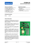
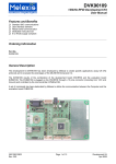
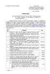
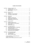
1
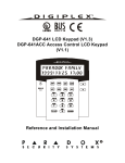
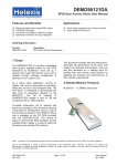
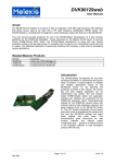
Calibration Software PTC04
User Manual
U S E R M A N UA L
C A L I BRA T I O N
S O F T WA R E
P TC 0 4 P RO G RA M ME R
User manual calibration software PTC04
UI_0PTC04AAMLX Rev. 1.35
Page 1 of 17
February 10
Calibration Software PTC04
User Manual
Contents:
Introduction
3
Calibration Setup
3
Requirements
3
Connections
3
RS232 settings
4
Check Calibration of the programmer
4
Calibration check
Before starting the calibration check
Manual voltmeter
The calibration check
There are three possible outcomes
5
5
8
9
9
What if the Calibration check failed
Measurement failed
Large deviation
12
12
13
Loggings
14
Calibration details
14
How does the calibration work?
ADC
DAC
14
14
15
What do we calibrate?
16
Disclaimer
User manual calibration software PTC04
UI_0PTC04AAMLX Rev. 1.35
17
Page 2 of 17
February 10
Calibration Software PTC04
User Manual
Introduction
In this document you’ll find
a description of:
• The Calibration Setup.
• How to proceed with the calibration
check.
• What if the calibration check fails?
• How does the calibration work?
• What do we calibrate?
Calibration Setup
Requirements
Figure 1: PTC04-DB-Calib.
For the calibration test you need:
• A high accuracy voltmeter;
• A PTC04 calibration board (PTC04-DB-Calib Supporting daughter board for calibration of PTC04
programmer).
The software has an automatic calibration feature. For this you need a Keithley 2000 or an Agilent (HP)
34401A multimeter. The Agilent 34401A multimeter is supported in the PTC04 User Interface revision
1.35 or higher.
If you use the automatic calibration feature, all
channels will be calibrated with the multimeter as
reference meter.
If a manual approach is used, only the first sensing
line is calibrated with the external reference meter.
For all the other channels the first sensing line will be
used as reference.
Connections
1. Replace the daughter board of the PTC04 with
the calibration board:
• Remove the cover of the PTC-04;
• Remove the PTC04 Daughter Board of the
MLX device;
• Plug in the PTC04 Calibration Board.
2. Connect the reference voltmeter to the BNC
connector or 4mm PCB Plugs (Both connections
are in parallel).
3. Connect the RS232 or USB cable to the PTC04
and the PC.
4. Connect the power supply of the PTC04.
Figure 2: Connections
User manual calibration software PTC04
UI_0PTC04AAMLX Rev. 1.35
Page 3 of 17
February 10
Calibration Software PTC04
User Manual
RS232 settings
The RS232 communication of the multimeter has to be configured as follows:
Keithley 2000 multimeter
Agilent (HP) 34401A multimeter
BAUD:
19.2 K
BAUD:
9600
FLOW:
NONE
PARITY:
EVEN: 7BITS
TX TERM:
CR
LANGUAGE:
SCPI
OR
BAUD:
4800
PARITY:
NONE: 8BITS
LANGUAGE:
SCPI
For configuration instructions, please consult the user’s manual of your multimeter.
All other settings are set by the software via RS232 commands.
Check Calibration of the programmer
Now your PTC programmer is connected and you can start-up the MPT software.
When the software is started, double click on PTC-04 in the UI modules list
or select from the menu “Tools Search devices All”
Figure 3: Melexis Programmable Toolbox.
User manual calibration software PTC04
UI_0PTC04AAMLX Rev. 1.35
Page 4 of 17
February 10
Calibration Software PTC04
User Manual
The software will search for all available devices. When a PTC programmer is found it will be initialized.
Otherwise the software will display a notification that no PTC devices have been found and will enter the
disconnected state.
If the connection failed, check the serial cable
and power connection or change the settings if
you have connected the programmer to a
different serial port.
To open the Calibration test module, press the
button Calibrate on the PTC04 User Interface.
Figure 4: User Interface PTC-04.
Calibration check
This module of the PTC-04 User Interface is used to verify if the calibration parameters of the programmer
are within tolerance. The software will check the power drivers (DAC) and the voltmeter (ADC), and
compare its results with the calibration parameters. If the calibration parameters are out of tolerance, they
can be corrected.
Before starting the calibration check
•
It is advised to leave the programmer powered up for minimum 30 to 60 minutes before starting
the calibration. For the accuracy of the calibration, it is important that the programmer is at
operating temperature.
•
Very important: do not connect any load on the connectors of the calibration board during the
calibration check. Any additional load will corrupt the calibration parameters and lead to an
unusable set-up. If this should happen, restart the calibrate check without a load connected to the
programmer.
•
If you have a Keithley 2000 or an Agilent (HP) 34401A Multimeter, select the correct multimeter
from the selection box (1) before you start the calibration check. The multimeter has to be
connected to the PC used for the calibration check. The default COM-port for the multimeter is
COM2. One can change the selected COM-port in the “COM port #” Edit-box (2).
User manual calibration software PTC04
UI_0PTC04AAMLX Rev. 1.35
Page 5 of 17
February 10
Calibration Software PTC04
User Manual
1
2
Figure 5: Calibration Check.
•
Press Verify Calibration to start the calibration.
You are reminded to leave your PTC04 powered up for minimum 30 to 60 minutes before starting the
calibration.
Figure 6: Start Check?
•
Press yes to continue.
User manual calibration software PTC04
UI_0PTC04AAMLX Rev. 1.35
Page 6 of 17
February 10
Calibration Software PTC04
User Manual
If you don’t use a Keithley 2000 or Agilent 34401A multi meter, you have to use a high accuracy
voltmeter. The accuracy of the calibration depends on the precision of the voltmeter and the number of
digits entered. With a manual voltmeter, the program will start with calibrating the internal voltmeter which
will be used to check the PTC04 programmer.
Figure 7: Proceed Check?
•
Press yes to continue.
At this stage the software will check if the calibration board and, if selected, the Keithley 2000 or Agilent
34401A Multimeter are connected. If the calibration board is not detected, a message is shown.
Figure 8: Check setup
•
If the setup is not complete, press No, switch of the programmer, check your setup and restart the
program.
User manual calibration software PTC04
UI_0PTC04AAMLX Rev. 1.35
Page 7 of 17
February 10
Calibration Software PTC04
User Manual
Manual voltmeter
If the Keithley 2000 or Agilent 34401A multimeter feature is not selected the program will ask you to put in
a few values from your voltmeter manually. These are used to calibrate the first sensing line of the PTC04. This sensing line will be used as reference meter for the calibration check.
Note: the accuracy of the calibration depends on the precision of the voltmeter and the number of digits
you enter.
Figure 9: Manual calibration internal reference meter.
•
Press OK to continue.
For the calibration of the internal reference meter, two series of 32 values are required. Once the internal
reference meter is calibrated the software will continue with the calibration check.
Note: the decimal separator of the software is “.” not “,”. If one uses a “,” as decimal separator, the
calculated parameters will be incorrect.
Figure 10: Input Box Manual Voltmeter.
•
Insert the value from the voltmeter in volt [V] and press OK.
Note: If you entered a wrong value, press Cancel. Two error messages are shown.
Figure 11: Check Measuring line 1 Failed
Figure 12: The calibration check has been cancelled.
•
Press OK on both messages to continue.
Now the calibration check is terminated, you can restart the calibration check.
User manual calibration software PTC04
UI_0PTC04AAMLX Rev. 1.35
Page 8 of 17
February 10
Calibration Software PTC04
User Manual
The calibration check
Now the calibration software will perform a number of measurements on all the ADC and DAC channels of
the programmer. This can take several minutes. At the end of the calibration check the program verifies if
a correction of the calibration parameters is needed.
Figure 13: Calibration Check
There are three possible outcomes
1. The program notifies you that the current calibration is out of tolerance and ask you if you want to
corrected the calibration parameters or not.
Figure 14: Calibrate?
•
If you press yes, the new calibration parameters are written into the PTC04.
•
If you press no, there are no modifications done.
User manual calibration software PTC04
UI_0PTC04AAMLX Rev. 1.35
Page 9 of 17
February 10
Calibration Software PTC04
User Manual
2. The program notifies you that the current calibration is within tolerance! No Correction of the
calibration parameters (Calibration) is needed.
Figure 15: Calibrate Anyway?
If no calibration is needed you can still choose to calibrate or not.
•
If you press yes, the new calibration parameters are written into the PTC04.
•
If you press no, there are no modifications done.
3. At the end of the calibration, the software verifies if the programmer was at temperature when the
calibration started. If the programmer was not at temperature, the following message is given.
Figure 16: Programmer is not at temperature.
It is advised not to calibrate (store the new calibration parameters in the programmer) when the
programmer is not at operating temperature. This is important for the accuracy of the PTC04 programmer.
•
If you press yes, the new calibration parameters are written into the PTC04.
•
If you press no, there are no modifications done.
User manual calibration software PTC04
UI_0PTC04AAMLX Rev. 1.35
Page 10 of 17
February 10
Calibration Software PTC04
User Manual
When you choose to calibrate (press yes), the new calibration parameters are written into the PTC04.
Afterwards the software verifies if the writing of the calibration data in the PTC04 was done correctly.
Figure 17: The Calibration check has been ended successfully.
Now the calibration check is completed.
The END status of the calibration check is shown in the status bar of the calibration window.
User manual calibration software PTC04
UI_0PTC04AAMLX Rev. 1.35
Page 11 of 17
February 10
Calibration Software PTC04
User Manual
What if the Calibration check failed
When the calibration fails, it is usually caused by a bad connection, measurement or incorrect input of
measured data. If this occurs, check the setup and redo the calibration check.
Very important:
• If the calibration check is done with a manual voltmeter, you have to take extra care that the
measurements are done correctly. These measurements are used to calibrate the first sensing
line of the PTC-04. This sensing line will be used as reference meter for the calibration check.
•
The accuracy of the calibration also depends on the precision of the voltmeter and the number of
digits you enter for each measurement.
•
The connection of the calibration board and the voltmeter are very imported. A bad connection or
any additional load will corrupt the calibration parameters.
•
The decimal separator of the software is “.” Not “,”. If one uses a “,” as decimal separator, the
calibration of the first sensing line will not be done correctly.
Measurement failed
The following error message is shown during the calibration procedure;
• If there is a bad connection in the setup. For example: between the PTC04 main board and the
calibration board.
•
When using a Keithley 2000 multimeter for the calibration, the failure can also be caused by a
wrong measurement of the Keithley. For example: communication error.
•
When you are using the manual calibration procedure. The software will perform a check on the
data you enter. If there is a large deviation from the expected data. The check will fail and the
calibration check is ended.
.
Figure 18: Check Measuring line 1 Failed
Figure 19: The calibration check has been cancelled.
To determine this:
• Press OK on both messages to cancel the calibration check.
•
Remove the calibration board, place it back and check the connections with the voltmeter. The
connection of the calibration board and the voltmeter are very imported. A bad connection or any
additional load will corrupt the calibration parameters.
•
After checking the setup, restart the calibration check. If the same channel fails again it is possible
that there is hardware damaged on the PTC04.
User manual calibration software PTC04
UI_0PTC04AAMLX Rev. 1.35
Page 12 of 17
February 10
Calibration Software PTC04
User Manual
Large deviation
When all the measurements are completed, the software calculates the new calibration parameter.
After the calculation of the calibration parameters, the software verifies if there is a large deviation with the
standard (expected) calibration parameters. If the deviation is too large the following warning message is
shown.
Figure 20: Large deviation of the calibration parameters.
In the main window you get a list of the channels that have a large deviation from the default values.
Figure 21: List of channels that have a large deviation.
The large deviation could be a result of incorrect reference measurements.
If it occurs:
• Remove the calibration board, place it back and check the connections with the voltmeter. The
connection of the calibration board and the voltmeter are very imported. A bad connection or any
additional load will corrupt the calibration parameters.
•
After checking the setup, restart the calibration check. If the same channel(s) fail(s) again it is
possible that there is hardware damaged on the PTC04.
User manual calibration software PTC04
UI_0PTC04AAMLX Rev. 1.35
Page 13 of 17
February 10
Calibration Software PTC04
User Manual
Loggings
Each time a calibration check is performed and the new correction parameters are saved in the PTC-04
programmer, the old and the new parameters are logged in a file called “Calibration Log.txt”. This file is for
information purpose only and is not used by the PTC-04 programmer.
Calibration details
How does the calibration work?
ADC
In the graph below, you have two curves: the measurements of the ADC (left Y-axis) and the reference
measurements of the external voltmeter (the right Y-axis). The internal voltage source is used as supply
(Set DAC X-axis). The purpose of the calibration check is to compare the ADC with the external high
precision voltmeter.
For the check, a number of voltage values are measured to calculate the difference between the ADC of
the PTC04 and the External Voltmeter which results in to correction parameters for offset and gain.
Ca libration check ADC
30000
8
ADC (ADC step)
6
20000
5
15000
4
3
10000
2
5000
External reference
voltmeter (V)
7
25000
1
0
0
500
1000
1500
0
2000
Se t DAC
ADC PTC-03
Ext. VOLTMETER
Graph 1
User manual calibration software PTC04
UI_0PTC04AAMLX Rev. 1.35
Page 14 of 17
February 10
Calibration Software PTC04
User Manual
DAC
In the 2nd graph, you have agene two curves: the Set DAC (left Y-axis) and the reference measurements
of the external voltmeter (the right Y-axis). The purpose of the calibration check is to compare the DAC
with the external high precision voltmeter.
Also for this check, a number of values are measured to calculate the difference between the DAC of the
PTC04 and the External Voltmeter which results in to correction parameters for offset and gain.
1800
8
1600
7
1400
6
1200
5
1000
4
800
3
600
400
2
200
1
0
0
2000
0
500
1000
1500
External reference
voltmeter (V)
DAC (DAC step)
Calibration check DAC
Se t Value
DA C PTC-03
Ext. V OLTMETER
Graph 2
At the end of the calibration check these values, of the ADC channels and the DAC, are compared with
the values stored in the PTC. If the parameters for offset and gain, that are currently stored in the PTC04,
are out of specifications in comparison with the new correction parameters, the software gives a warning
and asks if the new correction parameter may be saved.
User manual calibration software PTC04
UI_0PTC04AAMLX Rev. 1.35
Page 15 of 17
February 10
Calibration Software PTC04
User Manual
What do we calibrate?
Sensing lines:
There are four sensing lines with independent ground connection.
The source and reference that are used to calibrate the sensing lines are PPS 1 and the external
voltmeter.
Sensing line 1
Sensing line 2
Sensing line 3
Sensing line 4
channel 12 and Channel 28 (High sensitivity) of the ADC;
channel 13 and Channel 29 (High sensitivity) of the ADC;
channel 14 and Channel 30 (High sensitivity) of the ADC;
channel 15 and Channel 31 (High sensitivity) of the ADC.
PPS1:
For each PPS, the software checks the ADC first then the DAC and then the additional channels that are
connected to that source.
Voltmeter on the PPS1
PPS1
Current meter on the PPS1
PPS 5: IDD limiter PPS1
channel 0 and Channel 16 (High sensitivity) of the ADC;
channel 0 of the DAC;
channel 1 of the ADC;
channel 4 of the DAC.
PPS2:
Voltmeter on the PPS2
PPS2
Current meter on the PPS2
PPS 6: IDD limiter PPS2
channel 2 and Channel 18 (High sensitivity) of the ADC;
channel 1 of the DAC;
channel 3 of the ADC;
channel 5 of the DAC.
PPS3:
Voltmeter on the PPS3
PPS3
Current meter on the PPS3
PPS7: IDD limiter PPS3
channel 4 and Channel 20 (High sensitivity) of the ADC;
channel 2 of the DAC;
channel 5 of the ADC;
channel 6 of the DAC.
PPS4:
Voltmeter on the PPS4
PPS4
Current meter on the PPS4
PPS8: IDD limiter PPS4
User manual calibration software PTC04
UI_0PTC04AAMLX Rev. 1.35
channel 6 and Channel 22 (High sensitivity) of the ADC;
channel 3 of the DAC;
channel 7 of the ADC;
channel 7 of the DAC.
Page 16 of 17
February 10
Calibration Software PTC04
User Manual
Disclaimer
Devices sold by Melexis are covered by the warranty and patent indemnification provisions appearing in
its Term of Sale. Melexis makes no warranty, express, statutory, implied, or by description regarding the
information set forth herein or regarding the freedom of the described devices from patent infringement.
Melexis reserves the right to change specifications and prices at any time and without notice. Therefore,
prior to designing this product into a system, it is necessary to check with Melexis for current information.
This product is intended for use in normal commercial applications. Applications requiring extended
temperature range, unusual environmental requirements, or high reliability applications, such as military,
medical life-support or life-sustaining equipment are specifically not recommended without additional
processing by Melexis for each application.
The information furnished by Melexis is believed to be correct and accurate. However, Melexis shall not
be liable to recipient or any third party for any damages, including but not limited to personal injury,
property damage, loss of profits, loss of use, interrupt of business or indirect, special incidental or
consequential damages, of any kind, in connection with or arising out of the furnishing, performance or
use of the technical data herein. No obligation or liability to recipient or any third party shall arise or flow
out of Melexis’ rendering of technical or other services.
© 2010 Melexis NV. All rights reserved.
For the latest version of this document, go to our website at
www.melexis.com
Or for additional information contact Melexis Direct:
Europe, Africa, Asia:
America:
Phone: +32 13 670 495
E-mail: [email protected]
Phone: +1 603 223 2362
E-mail: [email protected]
ISO/TS 16949 and ISO14001 Certified
User manual calibration software PTC04
UI_0PTC04AAMLX Rev. 1.35
Page 17 of 17
February 10