1
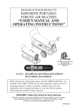
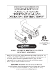
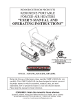
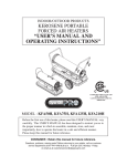
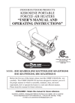
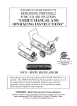
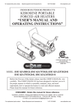
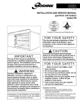
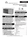
INDOOR/OUTDOOR PRODUCTS
KEROSENE PORTABLE
FORCED AIR HEATERS
“USER’S MANUAL AND
OPERATING INSTRUCTIONS”
COMPLIES WITH UL733 AND
ANSI A10.10-1998 CAN/CSA/
B140.0-03 AND CSA
B140.8-1967
MODEL: KFA50DGD, KFA80DGD, KFA135DGD
KFA180DGD, KFA220DGD
Before the first use of this heater, please read this USER’S MANUAL very
carefully. This USER’S MANUAL has been designed to instruct you as to
the proper manner in which to assemble, maintain, store, and most
importantly, how to operate the heater in a safe and efficient manner.
Please keep this manual for future reference.
CONSUMER : Retain this manual for future reference.
Questions, problems, missing parts? Before returning to your retailer, call our customer
service department at 877-447-4768 8:30 a.m. - 4:30 pm CST, Monday - Friday.
or email us at [email protected]
IMKFADG-HDc
NEVER LEAVE THE HEATER
UNATTENDED WHILE BURNING!
DANGER: IMPROPER USE OF THIS HEATER CAN RESULT IN SERIOUS INJURY OR DEATH
FROM BURNS, FIRE, EXPLOSION, ELECTRICAL SHOCK AND/OR CARBON
MONOXIDE POISONING.
WARNINGS:
1. RISK OF INDOOR AIR POLLUTION!
2. RISK OF BURNS / FIRE / EXPLOSION!
• Use this heater only in well ventilated areas. Provide at least a three-square foot (2,800 sq. cm.)
opening of fresh outside air for each 100,000 BTU/hr. of heater rating.
• People with breathing problems should consult a physician before using the heater.
•
Carbon monoxide poisoning: Early signs of carbon monoxide poisoning resemble the flu, with headaches, dizziness
and/or nausea. If you have these signs, the heater may not be working properly.
Get fresh air at once! Have the heater serviced. Some people are more affected by carbon monoxide than others.
These include pregnant women, persons with heart or lung disease or anemia, those under the influence of alcohol, or
those at high altitudes.
• Never use this heater in living or sleeping areas.
•NEVER use any fuel other than 1-K kerosene, #1/#2 diesel/fuel oil, JET A or JP-8 fuels in this heater.
•NEVER use use fuel such as gasoline, benzene, paint thinners or other oil compounds in this heater.
(RISK OF FIRE OR EXPLOSION)
•NEVER use this heater where flammable vapors may be present.
•NEVER refill the heaters fuel tank while heater is operating or is still hot.
while in operation. Do not touch. Keep children,
CAUTION:Hot
clothing and combustibles away from heater.
Minimum Clearances: Outlet: 8 feet (250cm) / Sides, top and rear: 4 feet (125cm)
•NEVER block air inlet (rear) or air outlet (front) of heater.
•NEVER use duct work in front or behind of heater.
•NEVER move, handle, service a hot, operating or plugged in heater.
•NEVER transport heater with fuel in it’s tank.
• When used with an optional thermostat or if equipped with a thermostat heater may start at any time.
•
ALWAYS locate heater on a stable and level surface.
•
ALWAYS keep children and animals away from heater.
• Bulk fuel storage should be a minimum of 25 ft. from heaters, torches, portable generators or other sources of ignition.
All fuel storage should be in accordance with federal, state or local authorities having jurisdiction.
3. RISK OF ELECTRIC SHOCK!
• Use only the electrical power (voltage and frequency) specified on the model plate of the heater.
• Use only a three-prong, grounded outlet and extension cord.
•
ALWAYS install the heater so that it is not directly exposed to water spray, rain, dripping water or wind.
•
ALWAYS unplug the heater when not in use.
PROPOSITION 65 WARNING: Fuels used in gas, wood-burning or oil fired appliances, and the
products of combustion of such fuels, contain chemicals known to the State of California to cause cancer,
birth defects and other reproductive harm.
MASSACHUSETTS RESIDENTS: Massachusetts state law prohibits the use of this heater in any
building which is used in whole or in part for human habitation. Use of this heating device in
Massachusetts requires local fire dept. permit (M.E.L.C. 148, Section 10A.)
CANADIAN RESIDENTS: Use of this heater shall be in accordance with authorities having
jurisdiction and CSA Standard B139.
NEW YORK CITY RESIDENTS: For use only at construction sites in accordance with applicable NYC
codes under NYCFD certificate of approval # 5034 and 5037.
1
NEVER LEAVE THE HEATER
UNATTENDED WHILE BURNING!
CONTENTS OF USER’S MANUAL
ITEM
PRECAUTIONS - SAFETY GUIDE..........................................................
1. INTRODUCTION................................................................................ 2. FEATURES...........................................................................................
3. UNPACKING AND ASSEMBLY........................................................
4. FUELS..................................................................................................
5. OVERVIEW OF HEATER DESIGN....................................................
6. FUELING YOUR HEATER.................................................................
7. OPERATION........................................................................................
8. LONG TERM STORAGE OF YOUR HEATER.................................
9. MAINTENANCE.................................................................................
10. REPLACING FUSE.............................................................................
11. TROUBLESHOOTING GUIDE..........................................................
12. WIRING DIAGRAM............................................................................
13. SPECIFICATIONS...............................................................................
14. EXPLODED PARTS DRAWING.........................................................
15. PARTS LIST.........................................................................................
PAGE #
1
2
2
4
6
7
8
8
9
10
14
15
16
17
18 & 21 & 24
19, 20 & 22, 23 & 25, 26
1. INTRODUCTION
Please read this USER’S MANUAL carefully. It will show you how to assemble, maintain, and operate the
heater safely and efficiently to obtain full benefits from its many built-in features.
2. FEATURES
Front Guard
Upper Shell
Hot Air Outlet
Handle
Lower Shell
Fuel Tank
Side Cover
Lamp
Thermostot Knob
(80DGD Model Only)
Fan Guard
Fuel Gauge
Fuel Cap
Power/Reset Switch
Power Cord
(Piggy Back, 80DGD Model Only)
Figure 1. KFA50DGD/KFA80DGD MODELS
2
NEVER LEAVE THE HEATER
UNATTENDED WHILE BURNING!
Front Handle
Rear Handle
Upper Shell
Hot Air Outlet
Shell Lower
Cord Wrap
Fuel Gauge
Fuel Cap
BTU Control Switch
Pressure Gauge
Fan Guard
Side Cover
Lamp
Thermostat Knob
Power Cord
(Piggy Back)
Room Temp. Display
Power/Reset Switch
Fuel Drain Bolt
10” Flat Free Wheel
Figure 2. KFA135DGD MODEL
Front Handle
Rear Handle
Upper Shell
Hot Air Outlet
Shell Lower
Cord Wrap
Fuel Gauge
Fuel Cap
BTU Control Switch
Pressure Gauge
Fan Guard
Side Cover
Lamp
Thermostat Knob
Power Cord
(Piggy Back)
Room Temp. Display
Power/Reset Switch
Fuel Drain Bolt
10” Flat Free Wheel
Figure 3. KFA180/220DGD MODELS
3
NEVER LEAVE THE HEATER
UNATTENDED WHILE BURNING!
3. UNPACKING AND ASSEMBLY
1. REMOVE THE HEATER AND ALL PACKING MATERIALS FROM THE BOX. (Fig. 4 and 5)
NOTE : Save the shipping carton and packing materials for future storage.
Wheel Support Frame
Wheel
Threaded Axle
Front Handle
Rear Handle
Handle
Cord Wrap
Hardware kit : HW-KFA1016
KFA50DGD
KFA80DGD
KFA180DGD
KFA220DGD
KFA135DGD
No
No
No
No
No
Yes
No
No
Yes
Yes
Yes
Yes
Yes
No
Yes
Yes
Yes
Yes
Yes
Yes
Yes
No
Yes
Yes
Figure 4. KFA50DGD/80DGD MODELS
Handle
Figure 5. KFA135DGD/180DGD/220DGD MODELS
Screws
Nuts
Wheels
(10” Flat Free)
Flange Screws
Cap Nuts S
Bushings
Cap Nuts L
Cord Wraps
Hardware Kit : HW-KFA1016
Front Handle
Rear Handle
Wheel Support Frame
Axle
4
NEVER LEAVE THE HEATER
UNATTENDED WHILE BURNING!
2.ASSEMBLY
For KFA50DGD/80DGD Models only
(Assembly time for this product is 3 minutes)
Handle
Tools Required
• Medium Phillips Screwdriver.
Remove Screws
1) Lift front guard for arrow direction and make
sure that guard’s wedged portion fits into the slit
hole on the upper housing.
2) Remove the pre-assembled screws on the shell
upper.
3) Align the holes in the upper housing with two
mounting holes on the handle as shown in
Figure 6.
4) Secure handle with the screws removed.
Screw
Front Guard
Wedged Portion
Slit Hole
Shell Upper
Figure 6. Assembling Handle
For KFA135DGD/180DGD/220DGD Models only (Assembly time for this product is 10 minutes)
Tools Required
• Medium Phillips Screwdriver.
• 3/4 inch socket or adjustable wrench
Assembling Handle & Wheel and Cord Wrap
1) Slide threaded axle through the rear section of the wheel support frane.
2) Slide one axle bushing on to each side of the axle. Slide one wheel on to each side of the axle.
Attach one cap nut on to each side of the threaded axle and tighten well.
3) Place heater on wheel support frame. Align the holes on fuel tank flange with holes on wheel support
frame.
4) Position the Handles on top of fuel tank flange.
Insert screws through handles, fuel tank flange and wheel support frames as shown in Figure 8 and
attach nut finger tight after each screw is inserted.
5) Align the hole on the handles with the mounting hole on the Cord Wrap.
Insert Screws through Cord Wrap, handles and attach nut finger tight after each screw is inserted.
6) After all screws are inserted, tighten nuts firmly.
5
NEVER LEAVE THE HEATER
UNATTENDED WHILE BURNING!
Front Handle
Screw
Cap Nut S
Rear Handle
Hot Air Outlet
Cord Wrap
Flange Screw
Fuel Tank
Flange
Air Inlet
Wheel Support Frame
Nut
Threaded Axle
Wheel Bushing
Wheel
Cap Nut L
Figure 7. Assembling Handle, Wheel and Cord wrap
CAUTION : DO NOT OPERATE heater without support frame assembled to tank.
NOTE : Heater should be inspected before each use, and at least annually by a qualified service person.
4. FUELS
For optimal performance of this heater, it is strongly suggested that 1-K kerosene be used. 1-K kerosene has
been refined to virtually eliminate contaminants, such as sulpher. Which can cause a rotten egg odor during
the operation of the heater. However, #1/#2 diesel/fuel oil, JET A or JP-8 fuels may also be used if 1-K kerosene
is not available. Be advised that these fuels do not burn as clean as 1-K kerosene, and care should be taken to
provide more fresh air ventilation to accomodate any added contaminants that may be added to the heated space.
#2 diesel/fuel oil heavier than 1-K kerosene in extreme cold temperatures without nontoxic anti-icer additives
will not ignite properly.
KEROSENE SHOULD ONLY BE STORED IN A BLUE CONTAINER THAT IS CLEARLY
MARKED “KEROSENE”. NEVER STORE KEROSENE IN A RED CONTAINER.
Red containers are associated with gasoline.
NEVER store kerosene in the living space. Kerosene should be stored in a well ventilated place outside the
living area.
NEVER use any fuel other than 1-K kerosene (#1/#2 diesel/fuel oil, JET A or JP-8 fuels are acceptable substitutes)
NEVER use fuel such as gasoline, benzene, alcohol, white gas, camp stove fuel, paint thinners, or other oil
compounds in this heater. These are volatile fuels that can cause an explosion or uncontrolled flames.
NEVER store kerosene in direct sunlight or near a source of heat.
NEVER use kerosene that has been stored from one season to the next. Kerosene deteriorates over time.
“OLD KEROSENE” WILL NOT BUR N PROPER LY IN THIS HE ATER.
6
NEVER LEAVE THE HEATER
UNATTENDED WHILE BURNING!
5. OVERVIEW OF HEATER’S DESIGN
Fuel System:
This heater is equipped with an electric
air pump that forces air through the air
line connected to the fuel intake and then
through a nozzle in the burner head.
When the air passes in front of the fuel
intake it causes fuel to rise from the tank
and into the burner nozzle. This fuel and
air mixture is then sprayed into the
combustion chamber in a fine mist.
“Sure Fire Ignition” : The electronic ignitor sends voltage to a specially designed spark plug.
The spark plug ignites the fuel and air mixture described above.
The Air System : The heavy duty motor turns a fan that forces air into and around the combustion chamber.
Here the air is heated and then forced out the front of the heater.
The Safety System :
A. Temperature Limit Control : This heater is equipped with a Temperature Limit Control designed to turn
off the heater should the internal temperature rise to an unsafe level. If this
device activates and turns your heater off it may require service.
MODELS
KFA50DGD
KFA80DGD
KFA135DGD
KFA180DGD
KFA220DGD
Internal Shut-Off Temp.
Plus/Minus 10 Degrees
Reset Temperature
Plus/Minus 10 Degrees
176˚F/80˚C
158˚F/70˚C
158˚F/70˚C
230˚F/110˚C
194˚F/90˚C
122˚F/50˚C
104˚F/40˚C
104˚F/40˚C
194˚F/90˚C
140˚F/60˚C
B. Electrical System Protection : This heater’s electrical system is protected by a fuse mounted to the PCB
assembly that protects it and other electrical components from damage.
If your heater fails to operate check this fuse first and replace as needed.
FUSE TYPE:
All Models
125 volt / 8 amps
C. Flame-Out Sensor : Utilizes a photocell to monitor the flame in burn chamber during normal operation.
It will cause the heater to shut-off should the burner flame extinguish.
7
NEVER LEAVE THE HEATER
UNATTENDED WHILE BURNING!
6. FUELING YOUR HEATER
NEVER FILL THE HEATER FUEL TANK IN THE LIVING SPACE : FILL THE TANK OUTDOORS.
DO NOT OVERFILL YOUR HEATER AND BE SURE HEATER IS LEVELED.
IMPORTANT NOTICE REGARDING FIRST IGNITION OF HEATER :
The first time you light the heater, it should be done outdoors. This allows the oils, etc. used in
manufacturing the heater to burn off outside.
WARNING!! : NEVER REFILL HEATER FUEL TANK WHEN HEATER IS OPERATING OR STILL HOT.
7. OPERATION
A.)VENTILATION
RISK OF INDOOR AIR POLLUTION/USE HEATER ONLY IN WELL VENTILATED AREAS.
Provide a fresh air opening of at least three square feet (2,800 sq. cm) for each 100,000 BTU/Hr.
rating. Provide extra fresh air if more heaters are being used.
Example : A KFA220DGD heater requires one of the following:
• a two-car garage door raised six inches (15.24 cm)
• a single-car garage door raised nine inches (22.86 cm)
• two, thirty-inch (76.20 cm) windows raised fifteen inches (38.1 cm)
B.)OPERATION
TO START HEATER
1. Fill fuel tank with kerosene or No. 1 fuel oil.
2. Attach fuel cap.
3. Plug power cord of heater into three-prong, grounded extension cord. Extension cord must be at
least six feet long.
Extension Cord Wire Size Requirements
• 6 to 100 feet (1.8 to 30.5 meters) long, use 16 AWG conductor.
• 101 to 200 feet (30.8 to 61 meters) long, use 14 AWG conductor.
4. Turn “THERMOSTAT CONTROL knob” to desired setting (setting range : 40˚F ~ 110˚F)
(KFA80DGD/KFA135/180/220DGD Models Only)
5. Push “BTU control Switch” to desired level “High or LOW” (See Figure 8.)
(KFA135/180/220DGD Models Only)
6. Push Power Switch to “ON” position, Power lndicator Lamp will light and heater will start.
7. After startup, push “BTU control switch” to desired level “High or Low”
NOTE: Room Temperature display explanations are as follows: (KFA80DGD/KFA135/180/220DGD Models only)
• When the room temperature is less 0℉, the LED display will show “Lo”
• When room temp is between 0℉ and 99℉, the number shown on the display is the current
room temperature.
• When room temperature is greater than 99℉, the LED display will show “Hi”
If heater does not start, the thermostat setting may be too low, turn “thermostat Control Knob” to
higher position to start heater. If heater still does not start, turn power switch to “OFF” and then to
“ON” position. If heater still does not start, see Troubleshootiong Guide on page15.
NOTE : User can select to operate the heater on two different BTU levels(High or Low).
To stabilize heater and prevent ignition delay, select BTU level after turning the heater on, or
while it is in operation by pushing the BTU control switch. If the heater started at low BTU level
in cold weather or low fuel tank, ignition failure can occur.
NOTE : In cold weather, ignition may be improved by holding a finger over the end of the relief valve or
block fanguard in half with newspaper etc. until the heater ignites.
8
NEVER LEAVE THE HEATER
UNATTENDED WHILE BURNING!
Room Temp. Display
Lamp
Btu Control Switch
Lamp
Power/Reset
Thermostat
Switch
Control Knob
(KFA80DGD MODEL ONLY)
KFA50DGD/80DGD Models
Thermostat
Control Knob
Btu Control Switch
Push to"HIGH"
Push to"LOW"
Power/Reset
Switch
KFA135DGD/180DGD/220DGD Models
Relief Valve
Fan Guard
Figure 8. Controls for All Models
NOTICE : The major electrical components of this heater are protected by a safety fuse mounted to the PCBboard.
If your heater fails to start, check this fuse first and replace as necessary. You should also check your
power source to insure that proper voltage and frequency are being supplied to the heater.
TO STOP HEATER
1. Turn switch to “OFF” and unplug power cord.
TO RESTART HEATER
1.Wait 10 seconds after stopping heater.
2. Repeat steps under to start heater.
Cover
Outlet
PIGGYBACK POWER CORD
WARNING : SHOCK HAZARD!
• Always cover electric outlet when not in use.
• Don’t plug and use a appliance more than 120V/60Hz 5A
current in this outlet.
8. LONG TERM STORAGE OF YOUR HEATER
FUEL TANK DRAIN
KFA80DGD/135DGD/180DGD/220DGD Models only
Figure 9. Piggy Back Power Cord
1. Drain fuel tank through fuel cap opening.
(For KFA50DGD/80DGD Models Only)
2. Remove fuel drain bolt from rear bottom side of fuel tank using 3/4” socket or adjustable wrench and drain.
(For KFA135DGD/180DGD/220DGD Models Only. See Figure 10)
3. Using a small amount of kerosene, swirl and rinse the inside of the tank.
NEVER mix water with the kerosene as it will cause rust inside the tank.
Pour the kerosene out making sure that you remove it all.
IMPORTANT : Do not store kerosene over summer months for use during next heating season.
Using old fuel could damage heater.
4. Reinstall fuel cap. Properly dispose of old and dirty fuel.
(For KFA50DGD/80DGD Models Only)
5. Reinstall fuel drain bolt to Fuel tank and tighten firmly using 3/4” socket
or adjustable wrench. (For KFA135DGD/180DGD/220DGD Models Only.
Seal
See Figure 10)
IMPORTANT : Before reinstalling the fuel drain bolt, make sure the
seal is on the bolt. If the seal is not used the bolt cannot
Fuel Drain Bolt
be installed correctly and the fuel tank will leak.
Figure 10. Fuel Drain Bolt
6. Store heater in dry well ventilated area. Make sure storage place is free
of dust and corrosive fumes.
7. Store the heater in the original box with the original packing material and keep the USER’S MANUAL
with the heater.
9
NEVER LEAVE THE HEATER
UNATTENDED WHILE BURNING!
9. MAINTENANCE
WARNING!! : NEVER SERVICE HEATER WHILE IT IS PLUGGED IN OR
WHILE HOT!
USE ORIGINAL EQUIPMENT REPLACEMENT PARTS. Use of third party or
other alternate components will void warranty and may cause unsafe operating
conditions.
A.) FUEL TANK
FLUSH EVERY 200 HOURS OF OPERATION OR
Screw
Upper Shell
AS NEEDED (SEE STORAGE, PAGE 9)
B.) AIR INTAKE FILTER
WASH AND DRY WITH SOAP AND WATER
EVERY 500 HOURS OF OPERATION OR AS
NEEDED.
- Remove screws along each side of heater using
medium phillips screwdriver.
- Lift upper shell off.
- Remove fan guard.
- Wash or replace air intake filter.
- Reinstall fan guard and upper shell.
C.) AIR OUTPUT FILTER, LINT FILTER
REPLACE EVERY 500 HOURS OF OPERATION
OR ONCE A YEAR.
- Remove upper shell and fan guard (See Air Intake Filter).
- Turn Air pressure gauge counter-clock wise and
remove.
- Remove end filter cover screws using medium
phillips screwdriver.
- Remove end filter cover.
- Replace air output and lint filter.
- Reinstall end filter cover and air pressure gauge.
- Reinstall fan guard and upper shell.
D.) FAN BLADES
CLEAN EVERY SEASON OR AS NEEDED.
- Remove upper shell (See Air Intake Filter).
- Use M6 allen wrench to loosen set screw
which holds fan blade to motor shaft.
- Slip fan blade off motor shaft.
- Clean fan blade using a soft cloth moistened with
kerosene or solvent.
- Dry fan blade thoroughly.
- Reinstall fan blade on motor shaft. Place fan
blade hub flush with end of motor shaft.
- Place set screw on flat of shaft. Tighten set screw
firmly (40-50 inch-pounds/4.5-5.6 N-m).
- Reinstall upper shell.
Air Intake Filter
Fan Guard
Figure 11. Air Intake Filter Access
Air Output Filter
End Filter Cover
Screw
Lint Filter
Pressure Gauge
Air Intake Filter
Figure 12. Air Outprt Filter Access
Set Screw
Flush
Motor Shaft
Fan Blade
Motor
10
Figure 13. Fan Assembly
NEVER LEAVE THE HEATER
UNATTENDED WHILE BURNING!
E.)NOZZLE
REMOVE DIRT IN NOZZLE AS NEEDED (SEE PAGE 16).
(For KFA50DGD/80DGD/135DGD/180DGD Models Only)
- Remove upper shell (See page 10).
- Remove fan blade (See page 10).
- Remove fuel and air line hoses from nozzle adaptor.
- Remove ignitor wire from spark plug.
- Remove spark plug from nozzle adaptor using medium
phillips screwdriver.
- Turn nozzle adaptor 1/9 turn(40°) to counter clock wise
and pull toward motor to remove. (See Figure 14)
- Place plastic hex-body into vise and lightlry tighten.
- Carefully remove nozzle from nozzle adaptor using 5/8”
socket wrench.
- Blow compressed air through face of nozzle.
(this will remove any dirt in nozzle)
- Reinstall nozzle into nozzle adaptor until nozzle seats.
Tighten 1/3 turn more using 5/8” socket wrench.
(40~45 inch-pounds)
- Reinstall nozzle adaptor to Bracket-Adaptor.
- Reinstall spark plug to nozzle adaptor.
- Attach ignitor wire to spark plug.
- Attach fuel and air line hoses to nozzle adaptor.
- Reinstall fan blade and upper shell.
(For KFA220DGD Model Only)
- Remove upper shell (See page 10).
- Remove fan (See page 10).
- Remove fuel and air line hoses from nozzle adaptor.
- Remove ignitor wire from spark plug.
- Remove spark plug from nozzle adaptor using medium
phillips screwdriver.
- Turn nozzle adaptor 1/8 turn (45°) to counter clock wise
and pull toward motor to remove. (See Figure 15)
- Place plastic hex-body into vise and lightly tighten.
- Carefully remove nozzle from nozzle adaptor using 5/8”
socket wrench.
- Blow compressed air through face of nozzle.
(this will remove any dirt in nozzle)
- Reinstall nozzle into nozzle adaptor until nozzle seats
Tighten 1/3 turn more using 5/8” socket wrench
(40~45 inch-pounds)
- Reinstall nozzle adaptor to burner bracket
- Reinstall spark plug to nozzle adaptor.
- Attach ignitor wire to spark plug.
- Attach fuel and air line hoses to nozzle adaptor.
- Reinstall fan blade and upper shell.
firmly (40-50 inch-pounds/4.5-5.6 N-m).
- Reinstall upper shell.
11
Combustion Chamber
Screw
Ignitor Wire
Bracket-Adaptor
Fuel Line
Air Line
Nozzle Face
Nozzle Adaptor
Nozzle
Nozzle Adaptor
Figure 14. Nozzle Replacement
Combustion Chamber
Screw
Ignitor Wire
Spark Plug
Nozzle Adaptor
Fuel Line
Bracket-Burner
Air Line
Nozzle Face
Nozzle Adaptor
Nozzle
Nozzle Adaptor
Figure 15. Nozzle Replacement
NEVER LEAVE THE HEATER
UNATTENDED WHILE BURNING!
F.) SPARK PLUG
CLEAN AND REGAP EVERY 600 HOURS
Nozzle Adaptor
GAP
Ignitor Wire
Spark Plug
Screw
Spark Plug
GAP
3.5mm / 0.138”
Figure 16. Spark Plug Regap
Nozzle Adaptor
Spark Plug
Screw
GAP
OPERATION OR REPLACE AS NEEDED.
(For KFA50DGD/80DGD/135DGD/180DGD Models Only)
- Remove upper shell (See page 10).
- Remove fan (See page 10).
- Remove ignitor wire from spark plug.
- Remove spark plug from nozzle adaptor using medium
phillips screwdriver.
- Clean and regap spark plug electrodes to 3.5mm gap.
- Reinstall spark plug to nozzle adaptor.
- Attach ignitor wire to spark plug.
- Reinstall fan and upper shell.
(For KFA220DGD Model Only)
- Remove upper shell (See page 10).
- Remove fan (See page 10).
- Remove ignitor wire from nozzle adaptor.
- Remove spark plug from nozzle adaptor using medium
phillips screwdriver.
- Clean and regap spark plug electrodes to 3.5mm gap.
(0.138”)
- Reinstall spark plug to nozzle adaptor.
- Attach ignitor wire to spark plug.
- Reinstall fan and upper shell.
Spark Plug
Ignitor Wire GAP
3.5mm / 0.138”
Figure 17. Spark Plug Regap
G.)PHOTOCELL
CLEAN PHOTOCELL ANNUALLY OR AS
NEEDED.
- Remove upper shell (See page 10).
- Remove fan (See page 10).
- Remove photocell from it’s mounting.
Clean photocell lens with cotton swab.
TO REPLACE:
- Remove side cover screws using medium phillips
screwdriver.
- Disconnect switch wires from power switch and
remove side cover.
- Disconnect wires from circuit board and remove
photocell.
- Install new photocell and connect wires to circuit
board.
- Replace switch wires to power switch and side cover.
- Replace fan and upper shell.
Side Cover
Power
Switch
Switch
Wires
Screw
Bracket
Photocell
Lens
• Incorrect
Install Photocell
• Correct
Figure 18. Photocell Replacement
12
NEVER LEAVE THE HEATER
UNATTENDED WHILE BURNING!
H.) FUEL FILTER
CLEAN OR REPLACE TWICE A HEATING
Fuel Filter
SEASON OR AS NEEDED.
- Remove side cover screws using medium phillips
screwdriver.
- Disconnect switch wires from power switch and
remove side cover.
- Pull fuel line off fuel filter neck.
- Turn fuel filter 90˚ to counter clockwise and pull to
remove (KFA50DGD/80DGD Models only).
- Turn fuel filter 90˚ to clockwise and pull to remove
(KFA135DGD/180DGD/220DGD Models only).
- Wash fuel filter with clean fuel and replace in tank.
- Attach fuel line to fuel filter neck.
- Replace switch wires to power switch.
- Reinstall side cover.
I.) PUMP PRESSURE ADJUSTMENT
NOTE:If the pump pressure needs to be adjusted,
make sure the heater is running on the
HIGH BTU setting.
- Push the BTU CONTROL Switch to HIGH.
(See Operation, page 8, KFA135DGD/180DGD/
220DGD Models only)
- Remove Pressure Gauge Plug from End Filter Cover.
(KFA50DGD/80DGD Models only)
- Start heater (See Operation, page 8)
Allow motor to reach full speed
- Adjust pressure (Using a flat blade screwdriver) Turn
relief valve to clockwise to increase pressure. Turn
relief valve to counter clockwise to decreasepressure.
- Stop heater (See Operation, page 8)
Pump Pressure
High BTU level Low BTU level
KFA50DGD
3.8 psi
N/A
KFA80DGD
3.8 psi
N/A
KFA135DGD
5.5 psi
3.5 psi
KFA180DGD
6.5 psi
4.5 psi
KFA220DGD
8.5 psi
6.5 psi
MODEL
NOTE:
USE ONLY ORIGINAL EQUIPMENT
REPLACEMENT PARTS.
Use of alternate or third party components will
void any warranty and may cause unsafe
operating condition.
13
Fuel line
Switch Wires
Screw
Side Cover
Power Switch
Figure 19. Fuel Filter Replacement
Flat blade
Screw driver
End Filter Cover.
Pressure Gauge Plug
Pressure Gauge
KFA50DGD/80DGD Models Only
Relief Valve
Pressure Gauge
BTU Control Switch
KFA135/180/220DGD Models only
Relief Valve
Figure 20. Adjusting Pump Pressure
NEVER LEAVE THE HEATER
UNATTENDED WHILE BURNING!
10. REPLACING FUSE
NOTICE : This heater is fuse protected.
If your heater fails to ignite, DO NOT RETURN YOUR HEATER TO THE
STORE.
Please follow the simple instructions below to inspect and change the fuse.
PROCEDURE FOR REPLACING FUSE
WARNING : SHOCK HAZARD
To prevent personal injury, unplug the power cord before replacing fuse.
1. Unplug heater.
2. Remove side cover screws using medium phillips screw driver.
3. Disconnect switch wires from power switch.
4. Remove fuse from fuse holder.(See Figure 21.)
5. Replace fuse with enclosed fuse.
WARNING : FIRE HAZARD
To avoid fire, Do not substitute with a higher or lower current rating.
6. Replace switch wires to power switch.
7. Replace side cover.
NOTE : Specified fuse rating : AC 125/8A
Fuse
Fuse Holder
KFA80DGD/135DGD/180DGD/220DGD Models
Screw
Side Cover
Power Switch
Switch Wire
Figure 21. Replacing Fuse
14
Fuse
KFA50DGD
Fuse Holder
NEVER LEAVE THE HEATER
UNATTENDED WHILE BURNING!
11. TROUBLESHOOTING GUIDE
TROUBLE
POSSIBLE CAUSE
CORRECTIVE ACTION
Heater ignites but MAIN PCB
assembly shuts heater off after a
short period of time.
(Indicator Lamp is flickering and
room temp. display indicates “ E1 “)
1.
2.
3.
4.
5.
6.
7.
8.
Wrong pump pressure.
Dirty Air Output,Air Intake
or Lint Filter.
Dirty Fuel Filter.
Dirt in Nozzle.
Dirty Photocell Lens.
Photocell Assembly not
Properly installed.(Not seeing the
flame)
Bad electrical connection
between photocell and MAIN PCB
assembly.
Defective Photocell.
1.
2.
3.
4.
5.
6.
7.
8.
See Pump Pressure Adjustment,
Page 13.
See Air Output, Air intake
and Lint Filters, page 10.
See Fuel Filter, Page 13.
See Nozzle, Page 11.
Clean Photocell Lens, Page 12.
Make sure photocell boot is
properly seated in bracket,
Page 12.
Check electrical components
See wiring diagram, Page 16.
Replace Photocell, Page 12.
Heater will not ignite but motor
runs for a short period
of time.(Indicator Lamp is flickering
and room temp.display
indicates “ E1 “)
1.
2.
3.
4.
5.
6.
7.
8.
No fuel in tank.
Wrong pump pressure.
Carbon deposits on spark plug and/
or improper gap.
Dirty fuel filter.
Dirt in Nozzle.
Water in fuel tank.
Bad electrical connection between
ignitor and MAIN PCB assembly.
Ignition wire is not attached to
spark plug.
1.
2.
3.
4.
5.
6.
7.
8.
Fill tank with kerosene.
See Pump Pressure Adjustment,
Page 13.
See Spark Plug, Page 12.
See Fuel Filter, Page 13.
See Nozzle, Page 11.
Flush fuel tank with clean
kerosene, Page 9.
Check electrical components
See wiring diagram, Page 16.
Attach ignition wire to spark plug.
See Spark Plug, Page 12.
Fan does not turn when heater is
plugged in and power switch was in
the “ ON “ Position.
(Indicator Lamp is on or flickering)
1. Thermostat setting is too low.
2. Bad electrical connection between
motor and MAIN PCB assembly.
1.
2.
Turn thermostat control knob to a
higher setting.
Check electrical connections, See
Wiring Diagram, Page 16.
(Indicator Lamp is flickering and
room temp. display indicates “E2”)
1. Sensor Failure.
1. Replace sensor.
See Wiring diagram, Page 16.
(Indicator Lamp is flickering and
room temp. display indicates “E3”)
1. Thermostat switch failure.
1. Replace switch.
See Wiring diagram, Page 16.
Heater will not turn-on
(Indicator Lamp is off)
1.
2.
3.
4.
1.
2.
3.
4.
Temperature limit safety device is
overheated.
No electrical power
Blown fuse.
Bad electrical connection between
temperature limit safety device and
PCB board.
15
Turn power switch to “OFF”
and allow to cool (about 10 min.)
Check to insure heater cord and
extension cord are plugged in.
Check power supply.
Replace safety fuse in PCB board.
Check electrical connections
See Wiring Diagram, Page 16.
NEVER LEAVE THE HEATER
UNATTENDED WHILE BURNING!
12. WIRING DIAGRAM
A) WIRING DIAGRAM (KFA50DGD Model)
CONTROL PCB
DISPLAY PCB
BLACK SPARK PLUG
RED
CN3
POWER LAMP
(LED)
CN1
2P
IGNITOR
RED
BLACK
CN1
ORANGE
CN7
BLACK
PUMP
MOTOR WHITE
RED
CAPACITOR
GREEN
15uF/230VAC
PW-W/H
EARTH
PW-BLK
CN2
POWER
SWITCH
POWER
PLUG
AC120V
60Hz
BLACK
BLACK
BLACK
GREEN
LIMIT
CONTROL
WHITE
PHOTO CELL
BLACK
BLACK
FUSE
8A/125VAC
WHITE
EARTH
B) WIRING DIAGRAM (KFA80DGD/135DGD/180DGD/220DGD Models)
CONTROL PCB
BLACK SPARK PLUG
RED
CN4
POWER LAMP
(LED)
RED
IGNITOR
BLACK
ORANGE
CN3
ROOM
SENSOR
THERMOSTAT
(TEMP. CONTROL)
RED
BLACK
PUMP
MOTOR WHITE
GREEN
CAPACITOR
CN2(AC2)/ WHT
CN6
CN5
CN1(AC1)/
EARTH
BLK
PHOTO
CELL
AC120V
60Hz
POWER
PLUG
BLACK
POWER
SWITCH
BLACK
GREEN
BLACK
LIMIT
CONTROL
FUSE
8A/125VAC
WHITE
EARTH
16
WHITE
BLACK
BLACK
MODEL
CAPACITOR
80DGD
15uF/230VAC
135/180/220DGD
20uF/350VAC
NEVER LEAVE THE HEATER
UNATTENDED WHILE BURNING!
16.7"(424mm)
13. SPECIFICATIONS
32.0"(813mm)
11.7"(297mm)
KFA50DGD/80DGD Models
H
D
135DGD
180DGD
220DGD
D 41.9”(1,063 mm) 47.4”(1,205 mm)
W 21.5”(547 mm) 23.1”(587 mm)
H 32.4”(824 mm) 33.5”(850 mm)
W
KFA135DGD/180DGD/220DGD Models
MODEL
BTU/Hr.
Fuel Consumption
- Gal./Hr( ./Hr)
HIGH
LOW
HIGH
LOW
Fuel Tank Capacity - Gal.( ) Fuel Tank Capacity
- Gal.(kgf/cm2)
Volt/Hz
Amps.
Phase
Size(D×W×H), Inch(mm)
Weight Lbs.(kg)
HIGH
LOW
KFA50DGD
KFA80DGD
KFA135DGD
KFA180DGD
KFA220DGD
N/A
N/A
95,000
140,000
180,000
50,000
80,000
135,000
180,000
220,000
0.38(1.44)
0.60(2.27)
1.02(3.86)
1.36(5.15)
1.66(6.28)
5.0(18.9)
5.0(18.9)
10.0(37.9)
13.0(49.2)
13.0(49.2)
N/A
N/A
0.72(2.73)
3.8(0.27)
120Vac/60hz
120Vac/60hz
120Vac/60hz
120Vac/60hz
120Vac/60hz
1
1
1
1
1
1.6
N/A
1.6
3.5(0.25)
2.5
6.5(0.46)
1.36(5.15)
3.8(0.27)
N/A
5.5(0.39)
1.06(4.01)
4.5(0.32)
3.2
8.5(0.60)
6.5(0.46)
3.7
32.0×11.7×16.7
(813×297×424)
32.0×11.7×16.7
(813×297×424)
41.9×21.5×32.4
(1,063×547×824)
47.4×23.1×33.5
(1,205×587×850)
47.4×23.1×33.5
(1,205×587×850)
26.9(12.2)
26.9(12.2)
52.2(23.7)
58.0(26.3)
60.2(27.3)
17
NEVER LEAVE THE HEATER
UNATTENDED WHILE BURNING!
14. EXPLODED PARTS DRAWING (KFA50DGD/80DGD Models Only)
NOTE : SPECIFY MODEL NUMBER AND PART NUMBER WHEN ORDERING PARTS.
BURNER HEAD ASSEMBLY
41
38
37
22-7
22-3
22-5
22-1
22-8
22-2
40
22-4
22-6
16
20 21
23
39
27
17
18
19
15
14
9
22
26
13
24
25
15
11
12
10
29
4
31
28
35
30
1
8
36
3
MOTOR AND PUMP ASSEMBLY
5
25-2
34
7
32
33
25-5
6
25-7
25-9
25-8
25-11
25-15
2
25-1
25-3
25-4
18
25-6
25-10
25-12
25-13
25-14
25-16
25-17
25-18
25-21
25-20
25-19
NEVER LEAVE THE HEATER
UNATTENDED WHILE BURNING!
15. PARTS LIST (KFA50DGD/80DGD Models Only)
KEY NO.
DESCRIPTION
1
2
3
4
5
6
7
8
9
10
11
12
13
14
15
16
17
18
19
20
21
22
22-1
22-2
22-3
22-4
22-5
22-6
22-7
22-8
22
24
25
25-1
25-2
25-3
25-4
25-5
25-6
25-7
25-8
25-9
25-10
25-11
25-12
Fuel Tank Assmebly
Fuel Drain-Bolt
Fuel Gauge
Fuel Filter Assmbly
Fuel Cap
Power Cord
Button Support
Display P.C.B Assembly
Shell Lower
Flange Screw
Bushing-Grommet(S)
Bushing-Grommet(L)
Air-Line
Temperature Limit Assembly
Flange-Screw
Chamber Assembly
Bracket Photocell
Screw-BH1
Photocell Assembly
Air Deflector
Flange Screw
Burner Head Assembly
Bracket-Adaptor
Nozzle
Washer-Nozzle Seal
Spring-Nozzle Seal
O-Ring
Nozzle Adaptor
Spark Plug
Bolt-Flange
Flange Screw
Fuel Line
Motor and Pump Assembly
Motor
Capacitor
Motor Support
Nut-Hex
Holder Capacitor
Pump Body
Bolt-BH Special
Rotor
Blade
Insert
End Pump Cover
Elbow
PART NO.
KFA50DGD
2151-0046-01
2156-0047-00
2155-0005-00
2151-0041-00
3980-0274-00
3713-0048-00
215A-0013-00
3111-0501-04
4319-0015-00
3231-0120-00
3231-0121-00
3341-0035-00
2153-0022-00
4319-0015-00
2152-0225-00
3131-0159-00
4311-0068-00
*SP-KFA1007
3131-0574-00
4319-0015-00
2152-0232-00
3131-0576-00
*SP-KFA1026
4349-0016-00
3431-0010-00
3311-0002-00
3231-0239-00
*SP-KFA1021
4329-0079-00
4319-0015-00
3341-0034-00
2154-0135-00
3970-0210-00
3820-0257-00
3121-0440-00
4331-0022-00
3541-0022-00
4321-0198-00
See SP-KFA10001
See SP-KFA10001
See SP-KFA10001
3531-0027-00
3231-0181-00
19
KFA80DGD
2151-0047-01
2156-0049-00
2155-0005-00
2151-0041-00
3980-0275-00
3111-0501-04
4319-0015-00
3231-0120-00
3231-0121-00
3341-0035-00
2153-0013-00
4319-0015-00
2152-0227-00
3131-0159-00
4311-0068-00
*SP-KFA1007
3131-0574-00
4319-0015-00
2152-0228-00
3131-0576-00
*SP-KFA1027
4349-0016-00
3431-0010-00
3311-0002-00
3231-0239-00
*SP-KFA1021
4329-0079-00
4319-0015-00
3341-0034-00
2154-0135-00
3970-0210-00
3820-0257-00
3121-0440-00
4331-0022-00
3541-0022-00
4321-0198-00
See SP-KFA10001
See SP-KFA10001
See SP-KFA10001
3531-0027-00
3231-0181-00
Quantity
1
1
1
1
1
1
2
1
1
4
1
2
1
1
1
1
1
2
1
2
2
1
1
1
2
1
1
1
1
1
2
1
1
1
1
1
2
1
1
2
1
4
1
1
1
NEVER LEAVE THE HEATER
UNATTENDED WHILE BURNING!
15. PARTS LIST (KFA50DGD/80DGD Models Only)
KEY NO.
25-13
25-14
25-15
25-16
25-17
25-18
25-19
25-20
25-21
26
27
28
29
30
31
32
33
34
35
36
37
38
39
40
41
KEY NO.
1
2
3
DESCRIPTION
Lint Filter
Bolt Flange
Output Filter
End Filter Cover
Ball
Spring
Adjusting Screw
Bolt Flange
Intake Filter
Fan Assembly
Bolt Headless Hex Socket
Plug
Main P.C.B Assembly
Screw-TH2S
Ignitor
Side Cover-Right
Power Switch
Flange Screw
Side Cover-Left
Flange Screw
Shell Upper
Clip Nut
Fan Guard
Flange Screw
Front Guard
DESCRIPTION
Rotor kit
Filter kit
Plug/Pump adjuster kit
PART NO.
KFA50DGD
2
See SP-KFA1005
4329-0016-00
See SP-KFA10052
3221-0029-00
See SP-KFA10063
See SP-KFA10063
See SP-KFA10063
4329-0016-00
See SP-KFA10052
2154-0009-00
4323-0004-00
3231-0054-00
215A-0048-00
4312-0046-00
39E0-0071-00
3121-0496-04
39A0-0191-00
4319-0015-00
3121-0190-00
4319-0015-00
3111-0502-04
3131-0182-00
3221-0074-00
4319-0015-00
3561-0066-00
PART NO.
KFA50DGD
SP-KFA1000
SP-KFA1005
SP-KFA1006
KFA80DGD
Quantity
2
See SP-KFA1005
4329-0016-00
See SP-KFA10052
3221-0029-00
See SP-KFA10063
See SP-KFA10063
See SP-KFA10063
4329-0016-00
See SP-KFA10052
2154-0009-00
4323-0004-00
3231-0054-00
215A-0073-00
4312-0046-00
39E0-0071-00
3121-0497-25
39A0-0191-00
4319-0015-00
3121-0350-00
4319-0015-00
3111-0502-04
3131-0182-00
3221-0074-00
4319-0015-00
3561-0066-00
KFA80DGD
SP-KFA1000
SP-KFA1005
SP-KFA1006
FOR TECHNICAL ASSISTANCE SEE YOUR LOCAL RETAILER OR
CONTACT US AT:
Phone : 1-877-447-4768
20
1
6
1
1
1
1
1
4
1
1
1
1
1
2
1
1
1
4
1
4
1
2
1
8
1
Quantity
1
1
1
NEVER LEAVE THE HEATER
UNATTENDED WHILE BURNING!
14. EXPLODED PARTS DRAWING (KFA135DGD/180DGD Models Only)
NOTE : SPECIFY MODEL NUMBER AND PART NUMBER WHEN ORDERING PARTS.
BURNER HEAD ASSEMBLY
37
20-3
20-5
20-1
20-7
20-8
20-2
20-4
39
20-6
14
18 19
21
38
25
15
16
17
13
12
7
20
24
11
22
23
15
9
10
28
4
1
8
30
26
35
27
29
36
3
5
MOTOR AND PUMP ASSEMBLY
34
33
23-2
6
31
32
23-5
23-7
23-9
23-8
23-11
23-15
2
23-1
23-3
23-4
21
23-6
23-10
23-12
23-13
23-14
23-16
23-17
23-18
23-21
23-20
23-19
NEVER LEAVE THE HEATER
UNATTENDED WHILE BURNING!
15. PARTS LIST (KFA135DGD/180DGD Models Only)
KEY NO.
1
2
3
4
5
6
7
8
9
10
11
12
13
14
15
16
17
18
19
20
20-1
20-2
20-3
20-4
20-5
20-6
20-7
20-8
21
22
23
23-1
23-2
23-3
23-4
23-5
23-6
23-7
23-8
23-9
23-10
23-11
23-12
23-13
23-14
DESCRIPTION
Fuel Tank Assmebly
Fuel Drain-Bolt
Fuel Gauge
Fuel Filter Assmbly
Fuel Cap
Power Cord
Shell Lower
Flange Screw
Bushing-Grommet(S)
Bushing-Grommet(L)
Air-Line
Temperature Limit Assembly
Flange-Screw
Chamber Assembly
Bracket Photocell
Screw-BH1
Photocell Assembly
Air Deflector
Flange Screw
Burner Head Assembly
Bracket-Adaptor
Nozzle
Washer-Nozzle Seal
Spring-Nozzle Seal
O-Ring
Nozzle Adaptor
Spark Plug
Bolt-Flange
Flange Screw
Fuel Line
Motor and Pump Assembly
Motor
Capacitor
Motor Support
Nut-Hex
Holder Capacitor
Pump Body
Bolt-BH Special
Rotor
Blade
Insert
End Pump Cover
Elbow
Lint Filter
Bolt Flange
KFA135DGD
2151-0048-01
4329-0072-00
2156-0050-00
2155-0001-00
2151-0041-00
3980-0275-00
3111-0506-04
4319-0015-00
3231-0120-00
3231-0121-00
3341-0036-00
2153-0013-00
4319-0015-00
2152-0230-00
3131-0159-00
4311-0068-00
*SP-KFA1007
3131-0575-00
4319-0015-00
2152-0193-00
3131-0576-00
*SP-KFA1003
4349-0016-00
3431-0010-00
3311-0002-00
3231-0180-00
*SP-KFA1021
4329-0079-00
4319-0015-00
3341-0032-00
2154-0141-00
3970-0211-00
3820-0258-00
3121-0439-00
4331-0022-00
3231-0182-00
3541-0022-00
4321-0198-00
See SP-KFA10001
See SP-KFA10001
See SP-KFA10001
3531-0027-00
3231-0181-00
See SP-KFA10052
4329-0016-00
22
PART NO.
KFA180DGD
2151-0049-01
4329-0072-00
2156-0051-00
2155-0001-00
2151-0041-00
3980-0275-00
3111-0508-04
4319-0015-00
3231-0120-00
3231-0121-00
3341-0038-00
2153-0023-00
4319-0015-00
2152-0242-00
3131-0159-00
4311-0068-00
*SP-KFA1007
3131-0575-00
4319-0015-00
2152-0194-00
3131-0576-00
*SP-KFA1004
4349-0016-00
3431-0010-00
3311-0002-00
3231-0180-00
*SP-KFA1021
4329-0079-00
4319-0015-00
3341-0032-00
2154-0142-00
3970-0212-00
3820-0258-00
3121-0439-00
4331-0022-00
3231-0182-00
3541-0022-00
4321-0198-00
See SP-KFA10001
See SP-KFA10001
See SP-KFA10001
3531-0027-00
3231-0181-00
See SP-KFA10052
4329-0016-00
Quantity
1
1
1
1
1
1
1
4
1
2
1
1
1
1
1
2
1
2
2
1
1
1
2
1
1
1
1
1
2
1
1
1
1
1
2
1
1
2
1
4
1
1
1
1
6
NEVER LEAVE THE HEATER
UNATTENDED WHILE BURNING!
15. PARTS LIST (KFA135DGD/180DGD Models Only)
KEY NO.
23-15
23-16
23-17
23-18
23-19
23-20
23-21
24
25
26
27
28
29
30
31
32
33
34
35
36
37
38
39
KEY NO.
1
2
3
DESCRIPTION
Output Filter
End Filter Cover
Ball
Spring
Adjusting Screw
Bolt Flange
Intake Filter
Fan Assembly
Bolt Headless Hex Socket
Pressure Gauge
BTU Control Switch
Main P.C.B Assembly
Screw-TH2S
Ignitor
Side Cover-Right
Power Switch
Window Display
Flange Screw
Side Cover-Left
Flange Screw
Shell Upper
Fan Guard
Flange Screw
DESCRIPTION
Rotor kit
Filter kit
Plug/Pump adjuster kit
KFA135DGD
PART NO.
KFA135DGD
SP-KFA1000
SP-KFA1005
SP-KFA1010
KFA180DGD
Quantity
See SP-KFA1005
3221-0076-00
See SP-KFA10103
See SP-KFA10103
See SP-KFA10103
4329-0016-00
See SP-KFA10052
2154-0007-00
4323-0004-00
3740-0049-00
2154-0070-00
215A-0074-00
4312-0046-00
39E0-0071-00
3121-0499-34
39A0-0191-00
3231-0113-00
4319-0015-00
3121-0354-00
4319-0015-00
3111-0509-04
3221-0075-00
4319-0015-00
See SP-KFA1005
3221-0076-00
See SP-KFA10103
See SP-KFA10103
See SP-KFA10103
4329-0016-00
See SP-KFA10052
2154-0004-00
4323-0004-00
3740-0049-00
2154-0070-00
215A-0073-00
4312-0046-00
39E0-0071-00
3121-0498-17
39A0-0191-00
3231-0113-00
4319-0015-00
3121-0352-00
4319-0015-00
3111-0507-04
3221-0075-00
4319-0015-00
2
PART NO.
2
KFA180DGD
SP-KFA1000
SP-KFA1005
SP-KFA1010
FOR TECHNICAL ASSISTANCE SEE YOUR LOCAL RETAILER OR
CONTACT US AT:
Phone : 1-877-447-4768
23
1
1
2
2
2
4
1
1
1
1
1
1
2
1
1
1
1
4
1
4
1
1
8
Quantity
1
1
2
NEVER LEAVE THE HEATER
UNATTENDED WHILE BURNING!
14. EXPLODED PARTS DRAWING (KFA220DGD Model Only)
NOTE : SPECIFY MODEL NUMBER AND PART NUMBER WHEN ORDERING PARTS.
BURNER HEAD ASSEMBLY
35
18-3
18-1
18-7
18-5
18-8
37
18-2
14
18
15
16
36
17
20 11
21
11
9
22 10
8
26
4
1
18-6
23
22
13
12
7
19
18-4
28
24
33
25
27
34
3
MOTOR AND PUMP ASSEMBLY
5
21-2
32
31
6
29
30
21-5
21-7
21-9
21-8
21-11
21-15
2
21-1
21-3
21-4
24
21-6
21-10
21-12
21-13
21-14
21-16
21-17
21-18
21-21
21-20
21-19
NEVER LEAVE THE HEATER
UNATTENDED WHILE BURNING!
15. PARTS LIST (KFA220DGD Model Only)
KEY NO.
DESCRIPTION
1
2
3
4
5
6
7
8
9
10
11
12
13
14
15
16
17
18
18-1
18-2
18-3
18-4
18-5
18-6
18-7
18-8
19
20
21
21-1
21-2
21-3
21-4
21-5
21-6
21-7
21-8
21-9
21-10
21-11
21-12
21-13
21-14
Fuel Tank Assmebly
Fuel Drain-Bolt
Fuel Gauge
Fuel Filter Assmbly
Fuel Cap
Power Cord
Shell Lower
Flange Screw
Bushing-Grommet(S)
Bushing-Grommet(L)
Air-Line
Temperature Limit Assembly
Flange-Screw
Chamber Assembly
Bracket Photocell
Screw-BH1
Photocell Assembly
Burner Head Assembly
Bracket Burner
Nozzle
Washer-Nozzle Seal
Spring-Nozzle Seal
O-Ring
Nozzle Adaptor
Spark Plug
Bolt-Flange
Flange Screw
Fuel Line
Motor and Pump Assembly
Motor
Capacitor
Supportor Motor
Nut-Hex
Holder Capacitor
Pump Body
Bolt-BH Special
Rotor
Blade
Insert
End Pump Cover
Elbow
Lint Filter
Bolt Flange
PART NO.
FA220DGD
2151-0049-01
4329-0072-00
2156-0052-00
2155-0001-00
2151-0041-00
3980-0275-00
3111-0504-04
4319-0015-00
3231-0120-00
3231-0121-00
3341-0036-00
2153-0005-00
2152-0050-00
4319-0015-00
3131-0159-00
4311-0068-00
*SP-KFA1007
2152-0124-00
3121-0477-00
*SP-KFA1011
4349-0016-00
3431-0010-00
3311-0002-00
3231-0180-00
*SP-KFA1021
4329-0079-00
4319-0015-00
3341-0039-00
2154-0137-00
3970-0137-00
3820-0258-00
3121-0439-00
4331-0022-00
3231-0182-00
3541-0050-00
4321-0198-00
See SP-KFA10221
See SP-KFA10221
See SP-KFA10221
3531-0027-00
3231-0181-00
See SP-KFA10052
4329-0016-00
25
Quantity
1
1
1
1
1
1
1
4
1
2
1
1
1
1
1
2
1
1
1
1
1
1
1
1
1
1
4
1
1
1
1
1
2
1
1
2
1
4
1
1
1
1
6
NEVER LEAVE THE HEATER
UNATTENDED WHILE BURNING!
15. PARTS LIST (KFA220DGD Model Only)
KEY NO.
21-15
21-16
21-17
21-18
21-19
21-20
21-21
22
23
24
25
26
27
28
29
30
31
32
33
34
35
36
37
KEY NO.
1
2
3
PART NO.
KFA220DGD
DESCRIPTION
Quantity
1
1
2
2
2
4
1
1
1
1
1
1
2
1
1
1
1
4
1
4
1
1
8
See SP-KFA1005
3221-0076-00
See SP-KFA10103
See SP-KFA10103
See SP-KFA10103
4329-0016-00
See SP-KFA10052
2154-0007-00
4323-0004-00
3740-0049-00
2154-0070-00
215A-0074-00
4312-0046-00
39E0-0071-00
3121-0499-35
39A0-0191-00
3231-0113-00
4319-0015-00
3121-0354-00
.
4319-0015-00
3111-0505-04
3221-0075-00
4319-0015-00
Output Filter
End Filter Cover
Ball
Spring
Adjusting Screw
Bolt Flange
Intake Filter
Fan Assembly
Bolt Headless Hex Socket
Pressure Gauge
BTU Control Switch
Main P.C.B Assembly
Screw-TH2S
Ignitor
Side Cover-Right
Power Switch
Window Display
Flange Screw
Side Cover-Left
Flange Screw
Shell Upper
Fan Guard
Flange Screw
PART NO.
KFA220DGD
DESCRIPTION
Rotor kit
Filter kit
Plug/Pump adjuster kit
2
Quantity
SP-KFA1022
SP-KFA1005
SP-KFA1010
FOR TECHNICAL ASSISTANCE SEE YOUR LOCAL RETAILER OR
CONTACT US AT:
Phone : 1-877-447-4768
26
1
1
2
NEVER LEAVE THE HEATER
UNATTENDED WHILE BURNING!
15. PARTS LIST (WHEELS AND HANDLE)
1) KFA50DGD/80DGD MODELS
KEY NO. DESCRIPTION
1
Handle
KFA50DGD
3231-0073-00
PART NO.
1
Quantity
KFA80DGD
3231-0073-00
1
2) KFA135DGD/180DGD/220DGD MODELS
KEY NO.
1
2
3
4
5
6
7
7-1
7-2
7-3
7-4
7-5
7-6
DESCRIPTION
Front Handle
Rear Handle
Wheel Support Frame
Wheel
Threaded Axle
Cord Wrap
Hardware Kit
Screw
Flange Screw
Cap Nut S
Nut
Bushing
Cap Nut L
PART NO.
KFA135DGD
KFA180DGD/220DGD
3551-0022-00
3551-0023-00
3551-0097-00
3551-0096-00
3551-0084-00
3551-0082-00
3720-0017-00
3720-0017-00
3551-0089-00
3551-0088-00
3221-0042-00
3221-0042-00
HW-KFA1016
HW-KFA1016
INCLUDED IN HARDWARE KIT
INCLUDED IN HARDWARE KIT
INCLUDED IN HARDWARE KIT
INCLUDED IN HARDWARE KIT
INCLUDED IN HARDWARE KIT
INCLUDED IN HARDWARE KIT
INCLUDED IN HARDWARE KIT
INCLUDED IN HARDWARE KIT
INCLUDED IN HARDWARE KIT
INCLUDED IN HARDWARE KIT
INCLUDED IN HARDWARE KIT
INCLUDED IN HARDWARE KIT
1
7-1
7-3
2
6
7-2
3
7-4
5
4
7-5
7-6
27
Quantity
1
1
1
2
1
2
1
8
4
4
8
2
2
Warranty
LIMITED WARRANTY:
This limited warranty is extended to the original retail purchaser of this Forced Air/Convection/Radiant Heater and warrants against any defect
in materials and workmanship for a period of one (1) year from the date of retail sale.GHP Group, Inc., at it’s option, will either provide
replacement parts or replace or repair the unit, when properly returned to the retailer where purchased or one of our service centers
as directed by GHP Group,Inc., within one (1) year of retail purchase. (Shipping costs, labour costs,etc. are the responsibility of the purchaser.)
DUTIES OF THE OWNER:
This heating appliance must be operated in accordance with the written instructions furnished with this heater. This warranty shall not excuse
the owner from properly maintaining this heater in accordance with the written instructions furnished with this heater. A bill of sale, canceled
check or payment record must be kept to verify purchase data and establish warranty period. Original carton should be kept in case of
warranty return of unit.
WHAT IS NOT COVERED:
1. Damage resulting from use of improper fuel.
2. Damage caused by misuse or use contrary to the owners manual and safety guidelines.
3. Damage caused by a lack of normal maintenance.
4. Fuses
5. Use of non-standard parts or accessories.
6. Damage caused in transit. Freight charges on warranty parts or heaters to and from the factory shall be the responsibility of the owner.
This warranty does not imply or assume any responsibility for consequential damages that may result from the use, misuse, or the lack of
routine maintenance of this heating appliance. A cleaning fee and the cost of parts may be charged for appliance failures resulting from lack of
maintenance. This warranty does not cover claims which do not involve defective workmanship or materials. FAILURE TO PERFORM
GENERAL MAINTENANCE (INCLUDING CLEANING) WILL VOID THIS WARRANTY.
THIS LIMITED WARRANTY IS GIVEN TO THE PURCHASER IN LIEU OF ALL OTHER WARRANTIES, EXPRESSED OR IMPLIED,
INCLUDING BUT NOT LIMITED TO THE WARRANTIES OF MERCHANTABILITY OF FITNESS FOR A PARTICULAR PURPOSE. THE
REMEDY PROVIDED IN THIS WARRANTY IS EXCLUSIVE AND IS GRANTED IN LIEU OF ALL OTHER REMEDIES. IN NO EVENT
WILL GHP GROUP, INC. BE LIABLE FOR INCIDENTAL OR CONSEQUENTIAL DAMAGES.
Some states do not allow limitations on how long an implied warranty lasts, so the above limitation may not apply to you. Some states do not
allow the exclusion or limitation of incidental or consequential damages so the above limitation or exclusion may not apply to you.
CLAIMS HANDLED AS FOLLOWS:
1. Contact your retailer and explain the problem.
2. If the retailer is unable to resolve the problem, contact our Customer Service Dept. detailing the heater model, the problem, and proof
of date of purchase.
3. A representative will contact you. DO NOT RETURN THE HEATER TO GHP GROUP, INC. unless instructed by our Representative.
This warranty gives you specific legal rights and you may also have other rights which vary from state to state.
TO REGISTER THE WARRANTY ON YOUR HEATER, PLEASE FILL OUT THIS CARD COMPLETELY
AND MAIL WITHIN 14 DAYS FROM DATE OF PURCHASE OR REGISTER ON-LINE AT www.ghpgroupinc.com
NAME:________________________________ PHONE: (
)__________________ EMAIL:_____________________________________
ADDRESS: ____________________________ CITY: _________________________ STATE:______________________ ZIP:____________
MODEL:_______________________________ SERIAL#:______________________ DATE PURCHASED:__________________________
DEALER PURCHASED FROM:__________________________________________ TYPE OF STORE: ___________________________
CITY & STATE WHERE PURCHASED:____________________________________ PRICE PAID: ________________________________
Please Take 1 Minute To Give Us Your Answers To The Following Questions.
All Responses Used Solely For Market Research And Are Held In Strict Confidence.
Who primarily decided this purchase?
Male
Female
18-24
25-39
40-59
60 and over of age?
Do you own any other portable heaters?
Yes
No If yes, type_______________________ brand_____________________________
How do you intend to use your new heater? Construction Site
Farm
Warehouse/Commercial
Garage/Outbuilding
Other
How did you become aware of this heater?
In-Store Display
Newspaper Ad
Magazine Ad
Friend/Relative
TV Commercial
Store Salesperson
Other_____________________________________________________________________
What made you select this heater?
Style Size/Portability
Price
Package
Brand
Other___________________________
Do you:
Own
Rent Would you recommend this heater to a friend?
Yes
No
Please give us your comments______________________________________________________________________________________
THANK YOU FOR COMPLETING THIS FORM!
Information will be held confidential.
28
WARRANTY REGISTRATION
IMPORTANT: We urge you to fill out your warranty registration card within fourteen (14)
days of date of purchase. You can also register your warranty on the internet at
www.ghpgroupinc.com. Complete the entire serial number. Retain this portion of the card
for your records.
GHP Group, Inc.
6440 W Howard St
Niles, IL 60714-3302
Tel: (877) 447-4768
www.ghpgroupinc.com
SAVE THIS CARD!
Place
Postage
Stamp
Here
GHP Group, Inc.
6440 W Howard St
Niles, IL 60714-3302