1
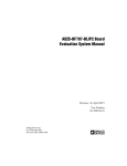
eCM-BF609 Hardware User Manual Version 1.4 Contact Bluetechnix Mechatronische Systeme GmbH Waidhausenstraße 3/19 A-1140 Vienna AUSTRIA [email protected] http://www.bluetechnix.com Document No.: 100-1217-1.4 Date: 2013-05-17 © Bluetechnix 2012 Table of Contents 1 2 Introduction ....................................................................................................................................... 5 1.1 Overview ................................................................................................................................... 5 1.2 Key Features ............................................................................................................................. 5 1.3 Applications ............................................................................................................................... 7 General Description .......................................................................................................................... 8 2.1 Functional Description ............................................................................................................... 8 2.2 Boot Mode ................................................................................................................................. 8 2.2.1 2.3 Core Module Memory ........................................................................................................ 9 2.3.2 Externally Addressable Memory (on connector) ................................................................ 9 5 6 7 KSZ5031RNLI Ethernet PHY .................................................................................................... 9 Specifications ................................................................................................................................. 10 3.1 4 Memory Map ............................................................................................................................. 9 2.3.1 2.4 3 Boot from onboard SPI Flash............................................................................................. 8 Electrical Specifications .......................................................................................................... 10 3.1.1 Operating Conditions ....................................................................................................... 10 3.1.2 Maximum Ratings ............................................................................................................ 10 3.1.3 ESD Sensitivity ................................................................................................................ 10 Connector Description .................................................................................................................... 11 4.1 Connector X1 .......................................................................................................................... 11 4.2 Connector X2 .......................................................................................................................... 15 Application Information ................................................................................................................... 19 5.1 Supply Voltage Decoupling ..................................................................................................... 19 5.2 Reset circuit ............................................................................................................................. 19 Mechanical Outline ......................................................................................................................... 20 6.1 Top View ................................................................................................................................. 20 6.2 Bottom View ............................................................................................................................ 20 6.3 Side View ................................................................................................................................ 21 6.4 Footprint .................................................................................................................................. 21 6.5 Connectors .............................................................................................................................. 21 Support ........................................................................................................................................... 22 7.1 General Support ...................................................................................................................... 22 7.2 Board Support Packages ........................................................................................................ 22 7.3 Blackfin® Software Support .................................................................................................... 22 7.3.1 BLACKSheep® OS .......................................................................................................... 22 7.3.2 LabVIEW .......................................................................................................................... 22 7.3.3 uClinux ............................................................................................................................. 22 7.4 Blackfin® Design Services ....................................................................................................... 22 © Bluetechnix 2012 7.4.1 8 Upcoming Products and Software Releases ................................................................... 22 Ordering Information ...................................................................................................................... 23 8.1 Predefined mounting options for eCM-BF609 ......................................................................... 23 8.2 Development Boards & Kits .................................................................................................... 23 9 Dependability .................................................................................................................................. 24 9.1 10 MTBF ....................................................................................................................................... 24 Product History ........................................................................................................................... 25 10.1 Version Information ............................................................................................................. 25 10.1.1 eCM-BF609-C-I-Q25S256F8 ........................................................................................... 25 10.1.2 eCM-BF609-C-C-Q25S256F8 ......................................................................................... 25 10.2 Anomalies ............................................................................................................................ 25 11 Document Revision History ........................................................................................................ 26 12 List of Abbreviations.................................................................................................................... 27 A List of Figures and Tables .............................................................................................................. 28 © Bluetechnix 2012 © Bluetechnix GmbH 2013 All Rights Reserved. The information herein is given to describe certain components and shall not be considered as a guarantee of characteristics. Terms of delivery and rights of technical change reserved. We hereby disclaim any warranties, including but not limited to warranties of non-infringement, regarding circuits, descriptions and charts stated herein. Bluetechnix makes and you receive no warranties or conditions, express, implied, statutory or in any communication with you. Bluetechnix specifically disclaims any implied warranty of merchantability or fitness for a particular purpose. Bluetechnix takes no liability for any damages and errors causing of the usage of this board. The user of this board is responsible by himself for the functionality of his application. He is allowed to use the board only if he has the qualification. More information is found in the General Terms and Conditions (AGB). Information For further information on technology, delivery terms and conditions and prices please contact Bluetechnix (http://www.bluetechnix.com). Warning Due to technical requirements components may contain dangerous substances. © Bluetechnix 2012 Hardware User Manual - eCM-BF609 Last change: 17 May 2013 Version 1.4 1 Introduction The Core Module eCM-BF609 is optimized for performance and parallel data processing. The module integrates processor, DDR2 RAM, NOR flash, Ethernet PHY and power supply at a size of 44x33mm! It is based on the high performance dual-core ADSP-BF609 from Analog Devices. The ADSP-BF609 integrates a co-processor unit to process signal and image algorithms (i.e. for pre- and coprocessing of video frames in ADAS applications). The eCM-BF609 is designed for industrial and commercial applications. It addresses 256MByte DDR2 SDRAM via its dedicated DDR2 interface and has an onboard SPI flash of 8MByte. 1.1 Overview Figure 1.1 shows the main components of the Core Module eCM-BF609. Figure 1.1: Main components of the eCM-BF609 module 1.2 Key Features Analog Devices Blackfin Processor ADSP-BF609 o ADSP-BF609BBCZ-5X (Temperature range: - 40°C – 85°C) 256MB DDR2 SDRAM o MEM2G16D2DABG-25I o DDR2-SDRAM Clock up to 400MHz o 128Mx16, 1Gbit at 1.8V © Bluetechnix 2013 Page | 5 Hardware User Manual - eCM-BF609 8MB SPI-Flash o MX25L6406EM2I-12G o 64Mbit at 3.3V Power supply o o Core voltage regulator ADP2118ACPZ-R7 1.25V at 2.5A DDR2 SDRAM ADP2108AUJZ-1.8-R7 1.8V at 600mA Low voltage Reset o Last change: 17 May 2013 Version 1.4 Module resets if power supply goes below 2.93V for at least 140ms Ethernet PHY o KSZ8031RNLI o Integrated terminal resistors o Can be disabled by analog switch to preserve the EPPI1 interface (see chapter 2.4) Connectors o 2x UART o 1x Up/Down/Rotary Counters o 8x Timer/Counters with PWM o 2x 3-Phase PWM Units (4-pair) o 3x SPORT o 2x SPI o 1x USB OTG o 3x Parallel Peripheral Interface o 1x Removable Storage Interface o 1x CAN o 2x TWI o 2x UART o 1x ADC Control Module (ACM) o 4x Link Ports o 1x Ethernet MAC (IEEE 1588) o 1x Ethernet MAC+PHY (IEEE 1588) o Data/Address Bus o GPIOs o Boot mode o JTAG o Power Supply o nRESET © Bluetechnix 2013 Page | 6 Hardware User Manual - eCM-BF609 1.3 o Buffered clocks (25MHz, SYS_CLKOUT) o Various control signals (see chapter 4) Last change: 17 May 2013 Version 1.4 Applications Parallel digital signal processing Automotive vision systems Imaging and consumer multimedia Stereo vision systems Portable media players Video conference applications Digital video camera systems © Bluetechnix 2013 Page | 7 Hardware User Manual - eCM-BF609 Last change: 17 May 2013 Version 1.4 2 General Description 2.1 Functional Description Figure 2.1: Functional overview 2.2 Boot Mode By default the Boot Mode is set to “No Boot – idle”. The boot mode pins are available on the connectors. BMODE[2:0] 000 Boot Source No Boot – idle 001 Memory boot 010 RSI master boot 011 SPI0 master boot SPI0 slave boot LP0 slave boot UART0 slave boot 100 110 111 Description The processor does not boot. Rather the boot kernel executes and IDLE instruction. Boot from an address in memory, by default this is the start address of flash memory Boot through the Removable Storage Interface(RSI) peripheral configure as a slave Boot through the Serial Port Interface (SPI0) peripheral configured as a slave Boot through the SPI0 peripheral configured as a master Boot through the Link Port (LP0) peripheral configured as a master Boot through the UART0 peripheral configured as a master Table 2.1: Boot modes 2.2.1 Boot from onboard SPI Flash The onboard SPI Flash supports double throughput of Serial Flash in read mode (DREAD) therefore the boot time can be shortened using SPIMCODE = 0x8 (DOR FAST_MODE) at the boot sequence. In this mode the © Bluetechnix 2013 Page | 8 Hardware User Manual - eCM-BF609 Last change: 17 May 2013 Version 1.4 SPI clock is set to SCLK/2 and the DREAD command is used to read the boot stream from flash. To use this feature the firmware must be linked with the option -bcode 0x8. 2.3 Memory Map 2.3.1 Core Module Memory Memory Type SPI FLASH 1) DDR2 SDRAM Access SPI0 and SPI0.nSEL1 1-Bit or 2-Bit access DMC Range: 0x00000000 – 0x0FFFFFFF Size 8MByte Comment MX25L6406EM2I-12G 256MByte MEM2G16D2DABG-25I, 128M x 16 Table 2.2: Memory Map 1) The SPI flash is connected to the SPI0 interface. SPI0.nSEL1 is used as chip select signal. See also chapter 2.2.1. 2.3.2 Externally Addressable Memory (on connector) The Static Memory Controller can be programmed to control up to four banks of memory-mapped devices. Each bank occupies a 64MByte segment regardless of the size of the device used. AMS Line nAMS0 nAMS1 nAMS2 nAMS3 Start Address 0xB0000000 0xB4000000 0xB8000000 0xBC000000 End Address 0xB3FFFFFF 0xB7FFFFFF 0xBBFFFFFF 0xBFFFFFFF Max. Size 64MByte 64MByte 64MByte 64MByte Table 2.3: External addressable memory 2.4 KSZ5031RNLI Ethernet PHY The ETH0 interface is connected through an analog switch with the Ethernet PHY KSZ5031RNLI. The connection is controlled by PG_13: PG_13 Level LOW HIGH Ethernet PHY Connected Disconnected Table 2.4: Connect/Disconnect Ethernet interface The Ethernet PHY is controlled in RMII mode and the 50MHz reference clock is generated by the PHY itself. No termination resistors are needed for the Ethernet interface since they are integrated in the PHY. © Bluetechnix 2013 Page | 9 Hardware User Manual - eCM-BF609 Last change: 17 May 2013 Version 1.4 3 Specifications 3.1 Electrical Specifications 3.1.1 Operating Conditions Symbol VIN I3V3 VOH VOL IIH IOZ fCCLK Parameter Input supply voltage 3.3V current High level output voltage Low level output voltage IO input current Three state leakage current Core clock frequency Min 3.15 2.4 - Typical 3.3 1100 - Max 3.45 0.4 10 10 500 Unit V mA V V µA µA MHz Table 3.1: Electrical characteristics 3.1.2 Maximum Ratings Stressing the device above the rating listed in the absolute maximum ratings table may cause permanent damage to the device. These are stress ratings only. Operation of the device at these or any other conditions greater than those indicated in the operating sections of this specification is not implied. Exposure to absolute maximum rating conditions for extended periods may affect device reliability. Symbol VIO VIN IOH /IOL TAMB TSTO TSLD φAMB Parameter Input or output voltage Input supply voltage Current per pin Ambient temperature Storage temperature Solder temperature for 10 seconds Relative ambient humidity (no condensing) Min -0.5 -0.5 0 -40 -55 Max 3.6 4.0 10 85 150 260 90 Unit V V mA °C °C °C % Table 3.2: Absolute maximum ratings 3.1.3 ESD Sensitivity ESD (electrostatic discharge) sensitive device. Charged devices and circuit boards can discharge without detection. Although this product features patented or proprietary protection circuitry, damage may occur on devices subjected to high energy ESD. Therefore, proper ESD precautions should be taken to avoid performance degradation or loss of functionality. © Bluetechnix 2013 Page | 10 Hardware User Manual - eCM-BF609 Last change: 17 May 2013 Version 1.4 4 Connector Description 4.1 Connector X1 Pin No. 1 2 3 4 5 6 7 8 9 Signal Name PF_00/PWM0_AL/EPPI0_D00/L P2_D0 PF_01/PWM0_AH/EPPI0_D01/L P2_D1 PF_02/PWM0_BL/EPPI0_D02/L P2_D2 PF_03/PWM0_BH/EPPI0_D03/L P2_D3 PF_04/PWM0_CL/EPPI0_D04/L P2_D4 PF_05/PWM0_CH/EPPI0_D05/ LP2_D5 PF_06/PWM0_DL/EPPI0_D06/L P2_D6 PF_07/PWM0_DH/EPPI0_D07/ LP2_D7 PE_06/SPORT1_ATDV/EPPI0_ FS3/LP3_CLK Type I/O I/O I/O I/O I/O I/O I/O I/O I/O 10 PE_07/SPORT1_BTDV/EPPI0_ FS2/LP3_ACK I/O 11 PE_08/PWM0_SYNC/EPPI0_F S1/LP2_ACK/ ACM0_T0 I/O 12 13 14 15 PE_09/EPPI0_CLK/LP2_CLK/n PWM0_TRIP0 GND PC_00/ETH0_RXD0/EPPI1_D0 0 PC_01/ETH0_RXD1/EPPI1_D0 1 I/O I/O *) I/O *) 16 PC_02/ETH0_TXD0/EPPI1_D02 I/O 17 PC_03/ETH0_TXD1/EPPI1_D03 I/O *) 18 PC_04/ETH0_RXERR/EPPI1_D 04 I/O *) 19 PC_05/ETH0_CRS/EPPI1_D05 I/O *) 20 PC_06/ETH0_MDC/EPPI1_D06 I/O 21 22 23 24 25 26 PC_07/ETH0_MDIO/EPPI1_D0 7 PC_08/EPPI1_D08 PC_09/ETH1_PTPPPS/EPPI1_ D09 PC_10/EPPI1_D10 PC_11/EPPI1_D11/ETH_PTPA UXIN PC_12/nSPI0_SEL7/EPPI1_D1 © Bluetechnix 2013 I/O *) I/O I/O I/O I/O I/O Function PF Position 0/PWM0 Channel A Low Side/EPPI0 Data 0/LP2 Data 0 PF Position 1/PWM0 Channel A High Side/EPPI0 Data 1/LP2 Data 1 PF Position 2/PWM0 Channel B Low Side/EPPI0 Data 2/LP2 Data 2 PF Position 3/PWM0 Channel B High Side/EPPI0 Data 3/LP2 Data 3 PF Position 4/PWM0 Channel C Low Side/EPPI0 Data 4/LP2 Data 4 PF Position 5/PWM0 Channel C High Side/EPPI0 Data 5/LP2 Data 5 PF Position 6/PWM0 Channel D Low Side/EPPI0 Data 6/LP2 Data 6 PF Position 7/PWM0 Channel D High Side/EPPI0 Data 7/LP2 Data 7 PE Position 6/SPORT1 Channel A Transmit Data Valid/EPPI0 Frame Sync 3 (FIELD)/LP3 Clock PE Position 7/SPORT1 Channel B Transmit Data Valid/EPPI0 Frame Sync 2 (VSYNC)/LP3 Acknowledge PE Position 8/PWM0 Sync/EPPI0 Frame Sync 1 (HSYNC)/LP2 Acknowledge/ACM0 External Trigger 0 PE Position 9/EPPI0 Clock/LP2 Clock/PWM0 Shutdown Input 0 PC Position 0/ETH0 Receive Data 0/EPPI1 Data 0 PC Position 1/ETH0 Receive Data 1/EPPI1 Data 1 PC Position 2/ETH0 Transmit Data 0/EPPI1 Data 2 PC Position 3/ETH0 Transmit Data 1/EPPI1 Data 3 PC Position 4/ETH0 Receive Error/EPPI1 Data 4 PC Position 5/ETH0 Carrier Sense/RMII Receive Data Valid/EPPI1 Data 5 PC Position 6/ETH0 Management Channel Clock/EPPI1 Data 6 PC Position 7/ETH0 Management Channel Serial Data/EPPI1 Data 7 PC Position 8/EPPI1 Data 8 PC Position 9/ETH1 PTP Pulse-Per-Second Output/EPPI1 Data 9 PC Position 10/EPPI1 Data 10 PC Position 11/EPPI1 Data 11/ETH PTP Auxiliary Trigger Input PC Position 12/SPI0 Slave Select Output 7/EPPI1 Page | 11 Hardware User Manual - eCM-BF609 Pin No. 27 28 29 30 Signal Name 2 PC_13/nSPI0_SEL6/EPPI1_D1 3/ETH_PTPCLKIN PC_14/nSPI1_SEL7/EPPI1_D1 4 PC_15/nSPI0_SEL4/EPPI1_D1 5 PB_15/ETH0_PTPPPS/EPPI1_ FS3 Last change: 17 May 2013 Version 1.4 Type I/O I/O I/O I/O 31 PD_06/nETH0_PHYINT/EPPI1_ FS2/TIMER0_ACI5 I/O *) 32 PB_13/ETH0_TXEN/EPPI1_FS 1/TIMER0_ACI6 I/O 34 35 36 37 38 39 PB_14/ETH0_REFCLK/EPPI1_ CLK 3V3 3V3 3V3 GND GND GND 40 nSYS_NMI/nSYS_RESOUT 41 44 45 46 47 48 SYS_EXTWAKE PD_08/nUART0_RX/TIMER0_A CI0 PD_07/nUART0_TX/TIMER0_A CI3 GND JTG_TCK JTG_TDO JTG_TDI JTG_TMS 49 nJTG_TRST 50 nJTG_EMU PE_10/ETH1_MDC/PWM1_DL/ RSI0_D6 33 42 43 51 52 53 54 55 56 57 58 PE_11/ETH1_MDIO/PWM1_DH /RSI0_D7 PD_05/SPI1_CLK/TIMER0_ACL K7 PD_13/SPI1_MOSI/TIMER0_AC LK5 PD_14/SPI1_MISO/TIMER0_AC LK6 PD_12/nSPI1_SEL1/EPPI0_D2 0/SPORT1_AD1/nSPI1_SS PD_15/nSPI1_SEL2/EPPI0_D2 1/SPORT1_AD0 PE_05/EPPI0_D23/SPORT1_A © Bluetechnix 2013 I/O *) Power Power Power Power Power Power I/O – 10k pull-up I I/O I/O Power I O I I I – 4k7 pull-down O I/O I/O I/O I/O I/O I/O I/O I/O Function Data 12 PC Position 13/SPI0 Slave Select Output 6/EPPI1 Data 13/ETH PTP Clock Input PC Position 14/SPI1 Slave Select Output 7/EPPI1 Data 14 PC Position 15/SPI0 Slave Select Output 4/EPPI1 Data 15 PB Position 15/ETH0 PTP Pulse-Per-Second Output/EPPI1 Frame Sync 3 (FIELD) PD Position 6/ETH0 RMII Management Data Interrupt/EPPI1 Frame Sync 2 (VSYNC)/TIMER0 Alternate Capture Input 5 PB Position 13/ETH0 Transmit Enable/EPPI1 Frame Sync 1 (HSYNC)/TIMER0 Alternate Capture Input 6 PB Position 14/ETH0 Reference Clock/EPPI1 Clock SYS Non-makeable Interrupt/SYS Reset Output SYS External Wake Control PD Position 8/UART0 Receive/TIMER0 Alternate Capture Input 0 PD Position 7/UART0 Transmit/TIMER0 Alternate Capture Input 3 JTAG Clock JTAG Data Out JTAG Data In JTAG Mode Select JTAG Reset JTG Emulation Output PE Position 10/ETH1 Management Channel Clock/PWM1 Channel D Low Side/RSI0 Data 6 PE Position 11/ETH1 Management Channel Serial Data/PWM1 Channel D High Side/RSI0 Data 7 PD Position 5/SPI1 Clock/TIMER0 Alternate Clock 7 PD Position 13/SPI1 Master Out, Slave In/TIMER0 Alternate Clock 5 PD Position 14/SPI1 Master In, Slave Out/TIMER0 Alternate Clock 6 PD Position 12/SPI1 Slave Select Output 1/EPPI0 Data 20/SPORT1 Channel A Data 1/SPI1 Slave Select Input PD Position 15/SPI1 Slave Select Output 2/EPPI0 Data 21/SPORT1 Channel A Data 0 PE Position 5/EPPI0 Data 23/SPORT1 Channel A Page | 12 Hardware User Manual - eCM-BF609 Pin No. 64 65 66 67 Signal Name FS PE_02/SPI1_RDY/EPPI0_D22/ SPORT1_ACLK PE_00/SPI1_D3/EPPI0_D18/SP ORT1_BD1 PE_01/SPI1_D2/EPPI0_D19/SP ORT1_BD0 PE_03/EPPI0_D16/ACM0_FS/S PORT1_BFS PE_04/EPPI0_D17/ACM0_CLK/ SPORT1_BCLK GND CLK_BUF GND PD_04/SPI0_CLK 68 PD_02/SPI0_MISO 69 80 PD_03/SPI0_MOSI PD_00/SPI0_D2/EPPI1_D16/nS PI0_SEL3 PD_01/SPI0_D3/EPPI1_D17/nS PI0_SEL2 PG_08/SPORT2_AD1/TIMER0_ TMR3/nPWM1_TRIP1 PG_09/SPORT2_AD0/TIMER0_ TMR4 PG_01/SPORT2_AFS/TIMER0_ TMR2/CAN0_TX PG_04/SPORT2_ACLK/TIMER0 _TMR1/CAN0_RX/TIMER0_ACI 2 PG_11/SPORT2_BD1/TIMER0_ TMR6/CNT0_UD PG_12/SPORT2_BD0/TIMER0_ TMR7/CNT0_DG PG_07/SPORT2_BFS/TIMER0_ TMR5/CNT0_ZM PG_10/nUART1_RTS/SPORT2 _BCLK GND 81 TWI0_SCL 82 TWI0_SDA 59 60 61 62 63 70 71 72 73 74 75 76 77 78 79 83 84 85 PG_01/SPORT2_AFS/TIMER0_ TMR2/CAN0_TX PG_04/SPORT2_ACLK/TIMER0 _TMR1/CAN0_RX/TIMER0_ACI 2 TWI1_SDA © Bluetechnix 2013 Last change: 17 May 2013 Version 1.4 Type I/O I/O I/O I/O I/O Power O Power I/O I/O – 10k pull-up I/O I/O I/O I/O I/O I/O I/O I/O I/O I/O I/O Power I/O – Open drain, 5V compatibl e I/O – Open drain, 5V compatibl e I/O I/O I/O – Function Frame Sync PE Position 2/SPI1 Ready/EPPI0 Data 22/SPORT1 Channel A Clock PE Position 0/SPI1 Data 3/EPPI0 Data 18/SPORT1 Channel B Data 1 PE Position 1/SPI1 Data 2/EPPI0 Data 19/SPORT1 Channel B Data 0 PE Position 3/EPPI0 Data 16/ACM0 Frame Sync/SPORT1 Channel B Frame Sync PE Position 4/EPPI0 Data 17/ACM0 Clock/SPORT1 Channel B Clock Buffered 25MHz PD Position 4/SPI0 Clock PD Position 2/SPI0 Master In, Slave Out PD Position 3/SPI0 Master Out, Slave In PD Position 0/SPI0 Data 2/EPPI1 Data 16/SPI0 Slave Select Output 3 PD Position 1/SPI0 Data 3/EPPI1 Data 17/SPI0 Slave Select Output 2 PG Position 8/SPORT2 Channel A Data 1/TIMER0 Timer 3/PWM1 Shutdown Input PG Position 9/SPORT2 Channel A Data 0/TIMER0 Timer 4 PG Position 1/SPORT2 Channel A Frame Sync/TIMER0 Timer 2/CAN0 Transmit PG Position 4/SPORT2 Channel A Clock/TIMER0 Timer 1/CAN0 Receive/ TIMER0 Alternate Capture Input 2 PG Position 11/SPORT2 Channel B Data 1/TIMER0 Timer 6/CNT0 Count Up and Direction PG Position 12/SPORT2 Channel B Data 0/TIMER0 Timer 7/CNT0 Count Down and Gate PG Position 7/SPORT2 Channel B Frame Sync/ TIMER0 Timer 5/CNT0 Count Zero Marker PG Position 10/UART1 Request to Send/SPORT2 Channel B Clock TWI0 Serial Clock TWI0 Serial Data PG Position 1/SPORT2 Channel A Frame Sync/TIMER0 Timer 2/CAN0 Transmit PG Position 4/SPORT2 Channel A Clock/TIMER0 Timer 1/CAN0 Receive/ TIMER0 Alternate Capture Input 2 TWI1 Serial Data Page | 13 Hardware User Manual - eCM-BF609 Pin No. Signal Name 86 TWI1_SCL 87 88 89 90 91 92 93 94 95 96 97 98 99 100 101 102 103 104 105 106 107 108 109 110 Last change: 17 May 2013 Version 1.4 Type Open drain, 5V compatibl e O – Open drain, 5V compatibl e PG_06/ETH1_REFCLK/RSI0_C LK/SPORT2_BTDV/nPWM1_TR IP0 PG_05/ETH1_TXEN/RSI0_CMD /PWM1_SYNC/ACM0_T1 PG_03/ETH1_TXD0/PWM1_AH /RSI0_D0 PG_02/ETH1_TXD1/PWM1_AL/ RSI0_D1 PG_00/ETH1_RXD0/PWM1_BH /RSI0_D2 PE_15/ETH1_RXD1/PWM1_BL/ RSI0_D3 PF_15/ACM0_A1/PPI0_D15/LP 3_D7 PF_14/ACM0_A0/PPI0_D14/LP 3_D6 PF_13/ACM0_A3/PPI0_D13/LP 3_D5 PF_12/ACM0_A2/PPI0_D12/LP 3_D4 PF_11/PPI0_D11/LP3_D3 I/O I/O I/O I/O I/O I/O I/O I/O I/O I/O I/O PF_10/ACM0_A4/PPI0_D10/LP 3_D2 PF_09/nSPI1_SEL6/PPI0_D09/ LP3_D1 PF_08/nSPI1_SEL5/PPI0_D08/ LP3_D0 GND GND GND GND GND GND GND GND GND GND I/O I/O I/O Function TWI1 Serial Clock PG Position 6/ETH1 Reference Clock/RSI0 Clock/SPORT2 Channel B Transmit Data Valid/ PWM1 Shutdown Input 0 PG Position 5/ETH1 Transmit Enable/RSI0 Command/PWM1 Sync/ACM0 External Trigger 1 PG Position 3/ETH1 Transmit Data 0/PWM1 Channel A High Side/RSI0 Data 0 PG Position 2/ETH1 Transmit Data 1/PWM1 Channel A Low Side/RSI0 Data 1 PG Position 0/ETH1 Receive Data 0/PWM1 Channel B High Side/RSI0 Data 2 PE Position 15/PWM1 Channel B Low Side/RSI0 Data 3/ETH1 Receive Data 1 PF Position 15/ACM0 Address 1/EPPI0 Data 15/LP3 Data 7 PF Position 14/EPPI0 Data 14/ACM0 Address 0/LP3 Data 6 PF Position 13/ACM0 Address 3/EPPI0 Data 13/LP3 Data 5 PF Position 12/ACM0 Address 2/EPPI0 Data 12/LP3 Data 4 PF Position 11/EPPI0 Data 11/LP3 Data 3/PWM0 Shutdown Input PF Position 10/ACM0 Address 4/EPPI0 Data 10/LP3 Data 2 PF Position 9/SPI1 Slave Select Output b/EPPI0 Data 9/LP3 Data 1 PF Position 8/SPI1 Slave Select Output b/EPPI0 Data 8/LP3 Data 0 Shield Shield Shield Shield Shield Shield Shield Shield Shield Shield Table 4.1: Connector description X1 © Bluetechnix 2013 Page | 14 Hardware User Manual - eCM-BF609 4.2 Last change: 17 May 2013 Version 1.4 Connector X2 Pin No. Type 103 Signal Name PB_04/nSMC0_AMS2/SMC0 _ABE0/SPORT0_AFS PB_05/nSMC0_AMS3/SMC0 _ABE1/SPORT0_ACLK nSMC0_AMS0 O – 47R serial Function PB Position 4/SMC0 Memory Select 2/SMC0 Byte Enable 0/SPORT0 Channel A Frame Sync PB Position 5/SMC0 Memory Select 3/SMC0 Byte Enable 1/SPORT0 Channel A Clock SMC0 Memory Select 0 104 SMC0_A01 O – 47R serial SMC0 Address 1 105 O – 47R serial SMC0 Address 2 PA Position 0/SMC0 Address 3/EPPI2 Data 0/LP0 Data 0 PA Position 1/SMC0 Address 4/EPPI2 Data 1/LP0 Data 1 PA Position 2/SMC0 Address 5/EPPI2 Data 2/LP0 Data 2 PA Position 3/SMC0 Address 6/EPPI2 Data 3/LP0 Data 3 PA Position 4/SMC0 Address 7/EPPI2 Data 4/LP0 Data 4 PA Position 5/SMC0 Address 8/EPPI2 Data 5/LP0 Data 5 PA Position 6/SMC0 Address 9/EPPI2 Data 6/LP0 Data 6 PA Position 7/SMC0 Address 10/EPPI2 Data 7/LP0 Data 7 PA Position 8/SMC0 Address 11/EPPI2 Data 8/LP1 Data 0 115 SMC0_A02 PA_00/SMC0_A03/EPPI2_D 00/LP0_D0 PA_01/SMC0_A04/EPPI2_D 01/LP0_D1 PA_02/SMC0_A05/EPPI2_D 02/LP0_D2 PA_03/SMC0_A06/EPPI2_D 03/LP0_D3 PA_04/SMC0_A07/EPPI2_D 04/LP0_D4 PA_05/SMC0_A08/EPPI2_D 05/LP0_D5 PA_06/SMC0_A09/EPPI2_D 06/LP0_D6 PA_07/SMC0_A10/EPPI2_D 07/LP0_D7 PA_08/SMC0_A11/EPPI2_D 08/LP1_D0 GND 116 3V3 Power 117 3V3 Power 118 3V3 Power 119 GND Power 120 GND Power 121 GND 122 SMC0_D00 123 SMC0_D01 124 SMC0_D02 125 SMC0_D03 126 SMC0_D04 127 SMC0_D05 128 SMC0_D06 129 SMC0_D07 130 SMC0_D08 131 SMC0_D09 Power I/O – 47R serial I/O – 47R serial I/O – 47R serial I/O – 47R serial I/O – 47R serial I/O – 47R serial I/O – 47R serial I/O – 47R serial I/O – 47R serial I/O – 47R 101 102 106 107 108 109 110 111 112 113 114 © Bluetechnix 2013 I/O I/O I/O I/O I/O I/O I/O I/O I/O I/O I/O Power SMC0 Data 0 SMC0 Data 1 SMC0 Data 2 SMC0 Data 3 SMC0 Data 4 SMC0 Data 5 SMC0 Data 6 SMC0 Data 7 SMC0 Data 8 SMC0 Data 9 Page | 15 Hardware User Manual - eCM-BF609 Pin No. Signal Name 132 SMC0_D10 133 SMC0_D11 134 SMC0_D12 135 SMC0_D13 136 SMC0_D14 137 SMC0_D15 138 nSYS_FAULT 139 nSYS_HWRST 140 nSMC0_BR 141 142 143 144 PB_01/nSMC0_AMS1/EPPI2 _FS1/LP0_ACK PB_04/nSMC0_AMS2/SMC0 _ABE0/SPORT0_AFS PB_05/nSMC0_AMS3/SMC0 _ABE1/SPORT0_ACLK nSMC0_AOE/SMC0_NORD V nSMC0_ARE Last change: 17 May 2013 Version 1.4 Type serial I/O – 47R serial I/O – 47R serial I/O – 47R serial I/O – 47R serial I/O – 47R serial I/O – 47R serial O – 10k pullup I/O – 470R pull-up I – 10k pull-up + 47R serial I/O I/O I/O Function SMC0 Data 10 SMC0 Data 11 SMC0 Data 12 SMC0 Data 13 SMC0 Data 14 SMC0 Data 15 SYS Fault Output SYS Processor Reset Control SMC0 Bus Request PB Position 1/SMC0 Memory Select 1/EPPI2 Frame Sync 1 (HSYNC)/LP0 Acknowledge PB Position 4/SMC0 Memory Select 2/SMC0 Byte Enable 0/SPORT0 Channel A Frame Sync PB Position 5/SMC0 Memory Select 3/SMC0 Byte Enable 1/SPORT0 Channel A Clock O – 47R serial SMC0 Output Enable/SMC0 NOR Data Valid O – 47R serial SMC0 Read Enable O – 47R serial I – 10k pull-up + 47R serial Power SMC0 Write Enable 148 nSMC0_AWE SMC0_ARDY/SMC0_NORW T GND 149 SYS_CLKOUT_BUF O Buffered SYS Processor Clock Output 150 GND Power 151 nc 152 Nc 153 SYS_BMODE0 154 SYS_BMODE1 155 SYS_BMODE2 156 nc 157 nc 158 nc 159 nc 160 GND 161 nc 162 PE_13/ETH1_CRS/PWM1_C H/RSI0_D4 I/O 163 PG_14/nUART1_RX/SYS_ID I/O 145 146 147 © Bluetechnix 2013 I – 10k pulldown I – 10k pulldown I – 10k pulldown SMC0 Asynchronous Ready/SMC0 NOR Wait SYS Boot Mode Control 0 SYS Boot Mode Control 1 SYS Boot Mode Control 2 Power PE Position 13/ETH1 Carrier Sense/RMII Receive Data Valid/ PWM1 Channel C High Side/RSI0 Data 4 PG Position 14/UART1 Receive/SYS Core 1 Idle Page | 16 Hardware User Manual - eCM-BF609 Pin No. Signal Name LE1/TIMER0_ACI1 Last change: 17 May 2013 Version 1.4 Type Function Indicator/TIMER0 Alternate Capture Input 1 164 PG_15/nUART1_TX/SYS_ID LE0/SYS_SLEEP/TIMER0_A CI4 I/O 165 PD_09/nSPI0_SEL5/nUART 0_RTS/nSPI1_SEL4 I/O 166 PE_14/ETH1_RXERR/SPOR T2_ATDV/TIMER0_TMR0 I/O 167 PD_10/SPI0_RDY/nUART0_ CTS/nSPI1_SEL3 I/O 168 PE_12/nETH1_PHYINT/PW M1_CL/RSI0_D5 I/O 169 USB0_VBC O PG Position 15/UART1 Transmit/SYS Core 0 Idle Indicator/SYS Processor Sleep Indicator/TIMER0 Alternate Capture Input 4 PD Position 9/SPI0 Slave Select Output 5/UART0 Request to Send/SPI1 Slave Select Output 4 PE Position 14/ETH1 Receive Error/SPORT2 Channel A Transmit Data Valid/ TIMER0 Timer 0 PD Position 10/SPI0 Ready/UART0 Clear to Send/SPI1 Slave Select Output 3 PE Position 12/ETH1 RMII Management Data Interrupt/ PWM1 Channel C Low Side/RSI0 Data 5 USB0 VBUS Control 170 USB0_VBUS I USB0 Bus Voltage 171 USB0_ID I USB0 OTG ID 172 USB0_DP I/O USB0 Data + 173 USB0_DM USB0 Data – 174 ETH_TX+ 175 ETH_TX- I/O I/O – 49R9 pull-up I/O – 49R9 pull-up 176 nc 177 ETH_RX+ 178 ETH_RX- 179 nc 180 ETH_LED0 181 nc PB_01/nSMC0_AMS1/EPPI2 _FS1/LP0_ACK PB_00/SMC0_NORCLK/EPP I2_CLK/LP0_CLK PB_09/nSMC0_BGH/SPORT 0_AD0/TIMER0_ACLK2 PB_12/nSMC0_BG/SPORT0 _BTDV/SPORT0_AD1/TIME R0_ACLK1 nc PB_11/SMC0_A25/SPORT0 _BD0/TIMER0_ACLK3 PB_10/SMC0_A24/SPORT0 _BD1/TIMER0_ACLK0 PB_08/SMC0_A23/EPPI2_D 17/SPORT0_BCLK PB_07/SMC0_A22/EPPI2_D 16/SPORT0_BFS 182 183 184 185 186 187 188 189 190 191 PB_06/SMC0_A21/SPORT0 _ATDV/TIMER0_ACLK4 © Bluetechnix 2013 I/O – 49R9 pull-up I/O – 49R9 pull-up O I/O I/O I/O I/O I/O I/O I/O I/O I/O Ethernet Ethernet Ethernet Ethernet Ethernet PB Position 1/SMC0 Memory Select 1/EPPI2 Frame Sync 1 (HSYNC)/LP0 Acknowledge PB Position 0/SMC0 NOR Clock/EPPI2 Clock/LP0 Clock PB Position 9/SMC0 Bus Grant Hang/SPORT0 Channel A Data 0/TIMER0 Alternate Clock 2 PB Position 12/SMC0 Bus Grant/SPORT0 Channel B Transmit Data Valid/ SPORT0 Channel A Data 1/TIMER0 Alternate Clock 1 PB Position 11/SMC0 Address 25/SPORT0 Channel B Data 0/TIMER0 Alternate Clock 3 PB Position 10/SMC0 Address 24/SPORT0 Channel B Data 1/TIMER0 Alternate Clock 0 PB Position 8/SMC0 Address 23/EPPI2 Data 17/SPORT0 Channel B Clock PB Position 7/SMC0 Address 22/EPPI2 Data 16/SPORT0 Channel B Frame Sync PB Position 6/SMC0 Address 21/SPORT0 Channel A Transmit Data Valid/TIMER0 Alternate Clock 4 Page | 17 Hardware User Manual - eCM-BF609 Pin No. Last change: 17 May 2013 Version 1.4 Type 201 Signal Name PA_15/SMC0_A20/EPPI2_D 15/LP1_D7 PA_14/SMC0_A19/EPPI2_D 14/LP1_D6 PA_13/SMC0_A18/EPPI2_D 13/LP1_D5 PA_12/SMC0_A17/EPPI2_D 12/LP1_D4 PB_03/SMC0_A16/EPPI2_F S3/LP1_CLK PA_11/SMC0_A15/EPPI2_D 11/LP1_D3 PA_10/SMC0_A14/EPPI2_D 10/LP1_D2 PB_02/SMC0_A13/EPPI2_F S2/LP1_ACK PA_09/SMC0_A12/EPPI2_D 09/LP1_D1 GND 202 GND Shield 203 GND Shield 204 GND Shield 205 GND Shield 206 GND Shield 207 GND Shield 208 GND Shield 209 GND Shield 210 GND Shield 192 193 194 195 196 197 198 199 200 I/O I/O I/O I/O I/O I/O I/O I/O I/O Function PA Position 15/SMC0 Address 20/EPPI2 Data 15/LP1 Data 7 PA Position 14/SMC0 Address 19/EPPI2 Data 14/LP1 Data 6 PA Position 13/SMC0 Address 18/EPPI2 Data 13/LP1 Data 5 PA Position 12/SMC0 Address 17/EPPI2 Data 12/LP1 Data 4 PB Position 3/SMC0 Address 16/EPPI2 Frame Sync 3 (FIELD)/LP1 Clock PA Position 11/SMC0 Address 15/EPPI2 Data 11/LP1 Data 3 PA Position 10/SMC0 Address 14/EPPI2 Data 10/LP1 Data 2 PB Position 2/SMC0 Address 13/EPPI2 Frame Sync 2 (VSYNC)/ LP1 Acknowledge PA Position 9/SMC0 Address 12/EPPI2 Data 9/LP1 Data 1 Shield Table 4.2: Connector description X2 *) Only available if Ethernet PHY is disconnected (see chapter 2.4) © Bluetechnix 2013 Page | 18 Hardware User Manual - eCM-BF609 Last change: 17 May 2013 Version 1.4 5 Application Information 5.1 Supply Voltage Decoupling Following table shows the pins that should be decoupled by capacitors. Pin No. Signal Name Capacitor value 34 3V3 47µF Tantal 34 3V3 100nF 35 3V3 100nF 36 3V3 100nF 116 3V3 100nF 117 3V3 100nF 118 3V3 100nF 170 USB0_VBUS 100nF Table 5.1: Recommended decoupling capacitors 5.2 Reset circuit The integrated reset circuit monitors the 3.3V power rail. If this voltage drops below 2.93V, the SYS_HWRST signal will be asserted. If the 3.3V voltage domain rises above this threshold, SYS_HWRST will be kept low for 140 to 280ms and will be released afterwards. PHY Ethernet of R 0 7 1 3 C 0 1 n 0 External Module D N G STM1001SWX6F D N G Core 3 S RESET 1 D D V D N G 2 4 3V3 SYS_HWRST BF60x of SYS_HWRST RST 3V3 The SYS_HWRST signal is an open collector output with an internal pull-up resistor of 470R. This signal can be used as external manual reset by connecting an external push-button that ties the signal to ground. Figure 5.1: Internal reset circuit 2 C 0 D N G n 0 1 1 2 Module Core 1 1 C 0 1 D N n 0 D N G D N G SN74LVC1G125DCK G S D N G 3 External T E S E R 4 Vcc 5 SYS_HWRST k 3V3 U 1 R 7 4 3V3 3V3 1 If SYS_HWRST is used to reset other devices then it is recommended to use a tri-state buffer to unload the internal reset circuit. Figure 5.2: Advanced reset circuit © Bluetechnix 2013 Page | 19 Hardware User Manual - eCM-BF609 Last change: 17 May 2013 Version 1.4 6 Mechanical Outline All dimensions are given in millimeters. Outline dimensions +/- 0,5mm. 6.1 Top View Figure 6.1: Mechanical outline (top view) 6.2 Bottom View Figure 6.2: Mechanical outline and Bottom Connectors (bottom view) © Bluetechnix 2013 Page | 20 Hardware User Manual - eCM-BF609 6.3 Last change: 17 May 2013 Version 1.4 Side View Figure 6.3: Mechanical outline (side view) 6.4 Footprint Figure 6.4: Footprint (top view) The footprint for Altium Designer is available on request. The used connectors can be found in Table 6.1. For detailed dimensions of the connectors please see the datasheet from the manufacturer’s homepage. 6.5 Connectors Connector Core Module X1 X2 Matching Connector X2 X1 Manufacturer Hirose Hirose Manufacturer Part No. FX-10A-100S/10SV FX-10A-100P/10SV Table 6.1: Core Module connector types The Core Module features 2 connectors, one male and one female. The base board uses the same connectors but oriented in the opposite way. © Bluetechnix 2013 Page | 21 Hardware User Manual - eCM-BF609 Last change: 17 May 2013 Version 1.4 7 Support 7.1 General Support General support for products can be found at Bluetechnix’ support site https://support.bluetechnix.at/wiki 7.2 Board Support Packages Board support packages and software downloads are for registered customers only https://support.bluetechnix.at/software/ 7.3 Blackfin® Software Support 7.3.1 BLACKSheep® OS BLACKSheep® OS stands for a powerfully and multithreaded real-time operating system (RTOS) originally designed for digital signal processing application development on Analog Devices Blackfin® embedded processors. This high-performance OS is based on the reliable and stable real-time VDK kernel from Analog Devices that comes with VDSP++ IDE. Of course BLACKSheep® OS is fully supported by all Bluetechnix Core-Modules and development hardware. 7.3.2 LabVIEW You can get LabVIEW embedded support for Bluetechnix Core Modules by Schmid-Engineering AG http://www.schmid-engineering.ch. 7.3.3 uClinux You can get uClinux support (boot loader and uClinux) for Bluetechnix Core Modules at http://blackfin.uClinux.org. 7.4 Blackfin® Design Services Based on more than seven years of experience with Blackfin, Bluetechnix offers development assistance as well as custom design services and software development. 7.4.1 Upcoming Products and Software Releases Keep up to date with all product changes, releases and software updates of Bluetechnix at http://www.bluetechnix.com. © Bluetechnix 2013 Page | 22 Hardware User Manual - eCM-BF609 Last change: 17 May 2013 Version 1.4 8 Ordering Information eCM - BF609 - C - C/I - Q25 S256 F8 - - Product Family Former name CM = Core Module Special SBC = Single Board Computer Custom Core Modules or specials CPU-Type uC = uclinux Equals the name of CPU Extra controllers mounted Connection-Type E = Ethernet A = BGA U = USB B = Border pad Flash [MB] C = Connector F = NOR Flash [MB] S = Special N = NAND Flash [MB] Operating Temperature Range RAM A = Automotive S = SDRAM [MB] C = Commercial I = Industry Crystal Frequency Notation: QXX[MHz] 8.1 Predefined mounting options for eCM-BF609 Article Number 100-1217-1 100-1218-1 Name eCM-BF609-C-C-Q25S256F8 (eCM-BF561) eCM-BF609-C-I-Q25S256F8 (eCM-BF561) Temperature Range Commercial Industrial Table 8.1: Ordering information 8.2 Development Boards & Kits Article Number 100-3401-1 Name Blackfin Evaluation Starter Package with eCM-BF609 including eDEV-BF6xx Type Development Kit with Core Module and carrier board Table 8.2: Ordering information NOTE: Custom Core Modules are available on request! Please contact Bluetechnix ([email protected]) if you are interested in custom Core Modules. © Bluetechnix 2013 Page | 23 Hardware User Manual - eCM-BF609 Last change: 17 May 2013 Version 1.4 9 Dependability 9.1 MTBF Please keep in mind that a part stress analysis would be the only way to obtain significant failure rate results, because MTBF numbers just represent a statistical approximation of how long a set of devices should last before failure. Nevertheless, we can calculate an MTBF of the Core Module using the bill of material. We take all the components into account. The PCB and solder connections are excluded from this estimation. For test conditions we assume an ambient temperature of 30°C of all Core Module components except the Blackfin® processor (80°C) and the memories (70°C). We use the MTBF Calculator from ALD (http://www.aldservice.com/) and use the reliability prediction MIL-217F2 Part Stress standard. Please get in touch with Bluetechnix ([email protected]) if you are interested in the MTBF result. © Bluetechnix 2013 Page | 24 Hardware User Manual - eCM-BF609 Last change: 17 May 2013 Version 1.4 10 Product History 10.1 Version Information 10.1.1 eCM-BF609-C-I-Q25S256F8 Version 1.0.0 1.1.0 Component Processor RAM Flash ETH-PHY Processor RAM Flash ETH-PHY Type ADSP-BF609-ENG MEM2G16D2DABG-25I MX25L6406EM2I-12G (8MB) KSZ8031RNLI ADSP-BF609BBCZ-5X MEM2G16D2DABG-25I MX25L6406EM2I-12G (8MB) KSZ8031RNLI Table 10.1: Overview eCM-BF609 Industrial product changes 10.1.2 eCM-BF609-C-C-Q25S256F8 Version 1.0.0 1.1.0 Component Processor RAM Flash Processor RAM Flash ETH-PHY Type ADSP-BF609-ENG MEM2G16D2DABG-25I MX25L6406EM2I-12G (8MB) ADSP-BF609BBCZ-5X MEM2G16D2DABG-25I MX25L6406EM2I-12G (8MB) KSZ8031RNLI Table 10.2: Overview eCM-BF609 product changes 10.2 Anomalies Version V1.0 V1.1 Date 2012 04 26 2013 05 13 Description The TWI0 signals must be swapped to be compatible with BLT products. No anomalies reported. Table 10.3 – Product anomalies © Bluetechnix 2013 Page | 25 Hardware User Manual - eCM-BF609 Last change: 17 May 2013 Version 1.4 11 Document Revision History Version 1 2 3 Date 2012 04 26 2013 03 11 2013 05 13 4 2013 05 17 Document Revision Preliminary release V1.0 of the document Updated connector X1 description Update table 2.3.1 Core Module Memory Update table 3.1.1 Operating Conditions Update view 6.3 Side View to eCM-BF609 V1.1 Update chapter 10 to eCM-BF609 V1.1 Update chapter 6 to eCM-BF609 V1.1 Add chapter 2.2.1 Update table 15 (BMODE0 and BMODE2 swapped) Table 11.1: Revision history © Bluetechnix 2013 Page | 26 Hardware User Manual - eCM-BF609 Last change: 17 May 2013 Version 1.4 12 List of Abbreviations Abbreviation ADI AI AMS AO CM DC DSP eCM EBI ESD GPIO I I²C I/O ISM LDO MTBF NC NFC O OS PPI PWR RTOS SADA SD SoC SPI SPM SPORT TFT TISM TSC UART USB USBOTG ZIF Description Analog Devices Inc. Analog Input Asynchronous Memory Select Analog Output Core Module Direct Current Digital Signal Processor Enhanced Core Module External Bus Interface Electrostatic Discharge General Purpose Input Output Input Inter-Integrated Circuit Input/Output Image Sensor Module Low Drop-Out regulator Mean Time Between Failure Not Connected NAND Flash Controller Output Operating System Parallel Peripheral Interface Power Real-Time Operating System Stand Alone Debug Agent Secure Digital System on Chip Serial Peripheral Interface Speech Processing Module Serial Port Thin-Film Transistor Tiny Image Sensor Module Touch Screen Controller Universal Asynchronous Receiver Transmitter Universal Serial Bus USB On The Go Zero Insertion Force Table 12.1: List of abbreviations © Bluetechnix 2013 Page | 27 Hardware User Manual - eCM-BF609 A Last change: 17 May 2013 Version 1.4 List of Figures and Tables Figures Figure 1.1: Main components of the eCM-BF609 module................................................................................... 5 Figure 2.1: Functional overview ........................................................................................................................... 8 Figure 5.1: Internal reset circuit ......................................................................................................................... 19 Figure 5.2: Advanced reset circuit ..................................................................................................................... 19 Figure 6.1: Mechanical outline (top view) .......................................................................................................... 20 Figure 6.2: Mechanical outline and Bottom Connectors (bottom view) ............................................................. 20 Figure 6.3: Mechanical outline (side view) ........................................................................................................ 21 Figure 6.4: Footprint (top view) .......................................................................................................................... 21 Tables Table 2.1: Boot modes ........................................................................................................................................ 8 Table 2.2: Memory Map ....................................................................................................................................... 9 Table 2.3: External addressable memory ............................................................................................................ 9 Table 2.4: Connect/Disconnect Ethernet interface .............................................................................................. 9 Table 3.1: Electrical characteristics ................................................................................................................... 10 Table 3.2: Absolute maximum ratings ............................................................................................................... 10 Table 4.1: Connector description X1 ................................................................................................................. 14 Table 4.2: Connector description X2 ................................................................................................................. 18 Table 5.1: Recommended decoupling capacitors ............................................................................................. 19 Table 6.1: Core Module connector types........................................................................................................... 21 Table 8.1: Ordering information ......................................................................................................................... 23 Table 8.2: Ordering information ......................................................................................................................... 23 Table 10.1: Overview eCM-BF609 Industrial product changes ......................................................................... 25 Table 10.2: Overview eCM-BF609 product changes ........................................................................................ 25 Table 10.3 – Product anomalies ........................................................................................................................ 25 Table 11.1: Revision history .............................................................................................................................. 26 Table 12.1: List of abbreviations ........................................................................................................................ 27 © Bluetechnix 2013 Page | 28