1
SPC-57
5.7” STN LCD Smart Panel
Computer with IntelR XscaleR CPU
and WindowsR CE.NET
Users Manual
Copyright
This document is copyrighted, © 2004. All rights are reserved. The original
manufacturer reserves the right to make improvements to the products described in
this manual at any time without notice.
No part of this manual may be reproduced, copied, translated or transmitted in any
form or by any means without the prior written permission of the original
manufacturer. Information provided in this manual is intended to be accurate and
reliable. However, the original manufacturer assumes no responsibility for its use, nor
for any infringements upon the rights of third parties that may result from such use.
Acknowledgements
IBM, PC/AT, PS/2 and VGA are trademarks of International Business Machines
Corporation.
Intel® is trademark of Intel Corporation.
Microsoft® Windows® CE.NET is a registered trademark of Microsoft Corp.
All other product names or trademarks are properties of their respective owners.
For more information on this and other Advantech products, please visit our websites
at:
http://www.advantech.com
For technical support and service, please visit our support website at:
http://eservice.advantech.com.tw/eservice/
This manual is for the SPC-57 series products.
1st. Edition:
July 2004
FCC Class A
This equipment has been tested and found to comply with the limits for a Class A
digital device, pursuant to Part 15 of the FCC Rules. These limits are designed to
provide reasonable protection against harmful interference when the equipment is
operated in a residential environment. This equipment generates, uses, and can radiate
radio frequency energy. If not installed and used in accordance with this user's manual,
it may cause harmful interference to radio communications. Note that even when this
equipment is installed and used in accordance with this user's manual, there is still no
guarantee that interference will not occur. If this equipment is believed to be causing
harmful interference to radio or television reception, this can be determined by
turning the equipment on and off. If interference is occurring, the user is encouraged
to try to correct the interference by one or more of the following measures:
• Reorient or relocate the receiving antenna
• Increase the separation between the equipment and the receiver
• Connect the equipment to a power outlet on a circuit different from that to which the
receiver is connected
• Consult the dealer or an experienced radio/TV technician for help
Warning! HIGH VOLTAGE!!!
Please do NOT touch the inverter between main board and LCD panel
with your hands or any other electric conductors.
Warning! Any changes or modifications made to the equipment which are not
expressly approved by the relevant standards authority could void your
authority to operate the equipment.
Packing List
Before you begin to use SPC, please make sure that the following materials have been
shipped.
z
z
z
z
z
z
z
z
SPC-57 Smart Panel Computer
Windows® CE.NET end user license agreement (for Windows® CE.NET
version)
Advantech Software Support CD (Windows® CE.NET)
• Readme.txt
• Datasheet
• User manual
•Windows® CE.NET 4.2 platforms SDK (for Windows® CE.NET)
• Microsoft ActiveSync Version 3.7 install files (for Windows® CE.NET).
Power connector
Plastic Stylus for touch-screen
1 x USB client ActiveSync cable
Warranty card
1 X 4P to 4P power cable (for SPC-57E only)
If any of these items are missing or damaged, contact your distributor or sales
representative immediately.
Additional Information and Assistance
Step 1: Visit the Advantech web site at www.advantech.com/risc where you can find
the latest information about the product.
Step 2: Contact your distributor, sales representative, or Advantech's customer service
center for technical support if you need additional assistance. Please have
the following information ready before you call:
• Product name and serial number
• Description of your peripheral attachments
• Description of your software (operating system, version, application software,
etc.)
• A complete description of the problems
• The exact wording of any error messages
Safety Instructions
1. Read these safety instructions carefully.
2. Keep this User's Manual for later reference.
3. Disconnect this equipment from any AC outlet before cleaning. Use a damp cloth.
Do not use liquid or spray detergents for cleaning.
4. For plug-in equipment, the power outlet socket must be located near the equipment
and must be easily accessible.
5. Keep this equipment away from humidity.
6. Put this equipment on a reliable surface during installation. Dropping it or letting it
fall may cause damage.
7. The openings on the enclosure are for air convection. Protect the equipment from
overheating. DO NOT COVER THE OPENINGS.
8. Make sure the voltage of the power source is correct before connecting the
equipment to the power outlet.
9. Position the power cord so that people cannot step on it. Do not place anything over
the power cord.
10. All cautions and warnings on the equipment should be noted.
11. If the equipment is not used for a long time, disconnect it from the power source
to avoid damage by transient over voltage.
12. Never pour any liquid into an opening. This may cause fire or electrical shock.
13. Never open the equipment. For safety reasons, the equipment should be opened
only by qualified service personnel.
14. If one of the following situations arises, get the equipment checked by service
personnel:
a. The power cord or plug is damaged.
b. Liquid has penetrated into the equipment.
c. The equipment has been exposed to moisture.
d. The equipment does not work well, or you cannot get it to work according
to the user's manual.
e. The equipment has been dropped and damaged.
f. The equipment has obvious signs of breakage.
15. DO NOT LEAVE THIS EQUIPMENT IN AN ENVIRONMENT WHERE
THE STORAGE TEMPERATURE MAY GO BELOW -20° C (-4° F) OR ABOVE
60° C (140° F). THIS COULD DAMAGE THE EQUIPMENT. THE EQUIPMENT
SHOULD BE IN A CONTROLLED ENVIRONMENT.
The sound pressure level at the operator's position according to IEC 704-1:1982 is
no more than 70dB (A).
DISCLAIMER: This set of instructions is given according to IEC 704-1. Advantech
disclaims all responsibility for the accuracy of any statements contained herein.
Wichtige Sicherheishinweise
1. Bitte lesen sie Sich diese Hinweise sorgfältig durch.
2. Heben Sie diese Anleitung für den späteren Gebrauch auf.
3. Vor jedem Reinigen ist das Gerät vom Stromnetz zu trennen. Verwenden Sie
Keine Flüssig-oder Aerosolreiniger. Am besten dient ein angefeuchtetes Tuch zur
Reinigung.
4. Die NetzanschluBsteckdose soll nahe dem Gerät angebracht und leicht zugänglich
sein.
5. Das Gerät ist vor Feuchtigkeit zu schützen.
6. Bei der Aufstellung des Gerätes ist auf sicheren Stand zu achten. Ein Kippen oder
Fallen könnte Verletzungen hervorrufen.
7. Die Belüftungsöffnungen dienen zur Luftzirkulation die das Gerät vor überhitzung
schützt. Sorgen Sie dafür, daB diese Öffnungen nicht abgedeckt werden.
8. Beachten Sie beim. AnschluB an das Stromnetz die AnschluBwerte.
9. Verlegen Sie die NetzanschluBleitung so, daB niemand darüber fallen kann. Es
sollte auch nichts auf der Leitung abgestellt werden.
10. Alle Hinweise und Warnungen die sich am Geräten befinden sind zu beachten.
11. Wird das Gerät über einen längeren Zeitraum nicht benutzt, sollten Sie es vom
Stromnetz trennen. Somit wird im Falle einer Überspannung eine Beschädigung
vermieden.
12. Durch die Lüftungsöffnungen dürfen niemals Gegenstände oder Flüssigkeiten
in das Gerät gelangen. Dies könnte einen Brand bzw. elektrischen Schlag auslösen.
13. Öffnen Sie niemals das Gerät. Das Gerät darf aus Gründen der elektrischen
Sicherheit nur von authorisiertem Servicepersonal geöffnet werden.
14.Wenn folgende Situationen auftreten ist das Gerät vom Stromnetz zu trennen und
von einer qualifizierten Servicestelle zu überprüfen:
a - Netzkabel oder Netzstecker sind beschädigt.
b - Flüssigkeit ist in das Gerät eingedrungen.
c - Das Gerät war Feuchtigkeit ausgesetzt.
d - Wenn das Gerät nicht der Bedienungsanleitung entsprechend funktioniert
oder Sie mit Hilfe dieser Anleitung keine Verbesserung erzielen.
e - Das Gerät ist gefallen und/oder das Gehäuse ist beschädigt.
f - Wenn das Gerät deutliche Anzeichen eines Defektes aufweist.
Der arbeitsplatzbezogene Schalldruckpegel nach DIN 45 635 Teil 1000 beträgt 70
dB(A) oder weiger.
DISCLAIMER: This set of instructions is given according to IEC704-1.
Advantech disclaims all responsibility for the accuracy of any statements
contained herein.
CHAPTER
1
General Information
This chapter gives background
Information of the SPC-57
Sections include:
• Introduction
• Specification
• LCD Specification
• Touchscreen Specification
• Power
• I/O ports
• Mounting
• Dimension and cutout
1.1 Introduction
Intel® XScale®, Ultra Low Power, Embedded Applications Anywhere!!
Advantech smart panel computers enable great embedded flexibility when powered
by Intel® XScale® technology. Built with an Intel PXA255 CPU, LCD display,
touchscreen, and pre-installed with Microsoft® Windows CE .NET 4.2 and LAN, the
SPC series provide the best cost-effective and stable solution to customers for a
diverse range of embedded applications. The great features of SPC, ultra low power,
compact size, IP65 front bezel, and fanless
Removable back cover: The back cover of the SPC series is easily removed to fit
customer application needs. With the flexibility of a removable back cover, customers
can better utilize the location and type of I/O by designing their own back for
seamless integration.
Dust and spill resistant: IP65 rated front bezel for protection from dust and water
damage.
Fanless and ultra low power consumption
Compact size
Rich connectivity for external accessories: GPS modules, wireless LAN modules,
GPRS modules are verified to work well with the SPC series.
SM bus for battery power: SPC keep the SM bus interface inside, users can equip
battery through SM bus to provide mobility on their own solution. The SM bus is
made through I2C
Versatile I/O: RS-232, RS-485, USB host, LAN, PCMCIA slot, CF slot, audio jack,
DIO, etc.
Applications
• Factory automation in manufacturing and warehousing
• Kiosks in public places – airports, information centers, railway stations and
shopping malls
• HMI: Human Machine Interface
• Entertainment – Gaming, Casino
• Hotel, Restaurant, and Hospitality
• Medical and health care in Hospital
• Portable/Mobile device
• In-vehicle device
1.2 Specifications
There are 2 models of SPC-57 series, SPC-57E and SPC-57C. SPC-57C is the fully
enclosure with standard external I/O connector. SPC-57E is without back cover,
without standard external I/O connector, and without Flash memory on board.
SPC-57E and SPC-57C can fulfill different applications and various demands from
the customer.
SPC-57C
System kernel
CPU
Intel PXA-255 200MHz on board
OS
Windows CE .NET 4.2
SDRAM
64MB SDRAM on board
Flash
32MB on board for OS pre-installed
WDT
PXA-255 internal
RTC
HT1381, backup by internal backup battery
Boot loader
1MB AMD Flash ROM for boot loader
Display
LCD
5.7” STN QVGA 320 x 240
Touch screen
4 wire resistant touch screen
VGA chip
PXA-255 internal
I/O
RS-232
Full 9 pin RS-232 X 3; D-sub 9-pin external connector X 1; Pin
headers inside the case X 2
RS-485
RS-485 X 1, D-sub 9-pin external connector
RJ-45
10/100 base-T RJ-45 connector X 1
USB
USB host X 2; USB client X 1
PCMCIA
PCMCIA slot type II X 1
CF
CF slot type II X 1
Digital I/O
8 DI & 8 DO. Pin header output. Provide API to access DIO
GPIO
8 GPIO. Pin header output inside the case. Default as hotkey
Audio
Audio line out jack X 1
Power
V-in range
DC 10V ~ 28V
Protection
Over current protection
Electric pole reverse protection
SM bus
For smart battery, pin headers
Power switch
1 power switch
Power conn
1 power connector
SW reset
Through system configurator to execute the SW reset
Mechanical
Dimension
210 X 155 X 41 (mm)
Material
SPCC
Certification
CE, FCC class A, UL
Environmental
Operating temp 0 degree C ~ 50 degree C
Storage temp
-20 degree C ~ 60 degree C
Water/dust
resistance
IP65 for front bezel
SPC-57E
System kernel
CPU
Intel PXA-255 200MHz on board
OS
Windows CE .NET 4.2
SDRAM
64MB SDRAM on board
Flash
N/A for SPC-57E. Users have to get CF card by themselves to store
the image file and boot from CF card
WDT
PXA-255 internal
RTC
HT1381, backup by internal backup battery
Boot loader
1MB AMD Flash ROM for boot loader
Display
LCD
5.7” STN QVGA 320 x 240
Touch screen
4 wire resistant touch screen
VGA chip
PXA-255 internal
I/O
RS-232
Full 9 pin RS-232 X 3; Pin headers output X 3
RS-485
RS-485 X 1, Pin headers output X 1
RJ-45
10/100 base-T Pin headers output X 1
USB
USB host X 2; USB client X 1; Pin headers output
PCMCIA
PCMCIA slot type II X 1
CF
CF slot type II X 1
Digital I/O
8 DI & 8 DO. Pin header output. Provide API to access DIO
GPIO
8 GPIO. Pin header output inside the case. Default as hotkey
Audio
Pin headers output
Power
V-in range
DC 10V ~ 28V
Protection
Over current protection; Electric pole reverse protection
SM bus
For smart battery, pin headers
Power switch
1 power switch
Power conn
1 power connector
SW reset
Through system configurator to execute the SW reset
Mechanical
Dimension
210 X 155 X 41 (mm)
Material
SPCC
Certification
CE, FCC class A, UL
Back cover
Without back cover; without I/O board;
Environmental
Operating temp 0 degree C ~ 50 degree C
Storage temp
-20 degree C ~ 60 degree C
Water/dust
resistance
IP65 for front bezel
SPC-57E: Smart Panel Computer without back cover and I/O board. Users have to get
their own CompactFlash card (more than 32MB) to restore Windows CE .NET 4.2
image. The system will boot from CF card.
1.3 LCD Specifications
LCD model
Nan Ya LMB61-23
Display type
STN color LCD
Size (Diagonal)
5.7”
Resolution
320 x 240 (VGA)
Maximum colors
256
Pixel pitch (WxH, mm)
2
0.36 X 0.36
Luminance (cd/m )
165 cd/m2
Contrast ratio
35
Response time
Rise 300 ms, Fall 80 ms
Lamp lifetime
20000 hours
1.4 Touchscreen Specifications
Type
Resistive
Base glass construction
Tempered Glass
Resolution
Continuous
Light transmission
75% typical
Durability
100000 activations for written characters
10000 activations for each single point
1.5 Power
SPC-57 works by 10 ~ 28Vdc power input. The maximum current is about 1.5A, and
the nominal power consumption is 6 Watts.
1.6 I/O Ports Arrangement
USB
Host
RJ-45
RS-232
RS-485
PCMCIA
Slot
Line out
jack
USB
Client
CompactFlash
TypeII Slot
Power
Switch
Power
Connector
1.7 Mounting
1.8 Dimension and cutout
CHAPTER
2
Getting Start
This chapter provides brief
instructions for operating the
SPC-57
2.1 Quick Starting
Step1: Unpack the SPC-57 from its packing. Please check the packing list at the
beginning of this manual.
Step2: Connect the power connector to 10 ~ 28 Vdc power source. The power source
can either be from a power adapter or an in-house power source.
Step3: Connect the power source to the system power supply.
Step4: Plug in the power lines and turn on the system power switch, you will see the
Welcome screen of Windows® CE.NET. Then you can start to use SPC-57.
Step5: Turn on the power switch.
Step6: Calibrate the touchscreen.
2.2 Supplying Power to SPC
2.1.1 Supplying Power to SPC-57C
1. SPC accepts only DC power, not AC power
2. The DC input range for SPC is 10V ~ 28V.
3. Install the Vcc cable and GND cable into the male power connector (male power
connector is in the package of SPC)
Vcc
GND
4. Plug the male power connector into female power connector in SPC.
5. Turn on the power switch
2.1.2 Supplying Power to SPC-57E
1. SPC accepts only DC power, not AC power
2. The DC input range for SPC is 10V ~ 28V.
3. Use the power cable (in SPC-57E package) to connect the board of SPC-57 and
power source.
Power Connector
Connect to the
power source
4. If the power cable included in the SPC-57E package is not suitable to users’
application, users have to make their own cable to supply power to SPC.
CHAPTER
3
The Engine of the SPC-57
This chapter details hardware’s
setting and functionality in the
SPC-57
Sections include:
• PCM-7230 SBC for SPC-57
• I/O Board
• LCD and touch-screen
• Power system
This chapter will detail hardware setting and functionality in the SPC-57. Following
will introduce (1) PCM-7230 SBC for SPC-57; (2) The I/O Board (there is no I/O
board of SPC-57E) (3) LCD and touch-screen; (4) Power system.
3.1 PCM-7230 Mainboard for SPC-57
The Engine of SPC-57 is constructed by the combination of 2 PCBA – one
mainboard and one I/O board. The mainboard is slightly modified based on
Advnatech standard product PCM-7230 to fulfill SPC-57 specification. In this manual,
we will still use PCM-7230 to mean the mainboard although it is slightly different
from our standard product. The PCM-7230 SBC for SPC-57 is a 3.5” (145mm x 102
mm x 21.1mm) single board computer with the Intel® PXA255 processor running at
200 MHz. The milli-watt power consumption by its kernel makes the PCM-7230
suitable for power conscious applications.
3.1.1 Specification
Model
PCM-7230 SBC for SPC-57
Model
PCM-7230 SBC for SPC-57
CPU
Kernel
part
Intel® PXA255 processor at 200 MHz
System
memory
1MB NOR flash for bootloader and 64MB SDRAM
Memory
Module
N/A
WDT
PXA-255 Internal (2, 5, 10 Sec as default)
RTC
HT-1381 with rechargeable coin battery
Power Input
OS
DC 10V~28V, with power protect (protect for over voltage,
over current & short).
Microsoft® Windows® CE.NET 4.2
Three full-function RS-232 ports and one RS-485 w/ AFC
I/O ports
-COM1 full-function transceiver level RS-232
Serial Ports
-COM2 full-function transceiver level RS-232
-COM3 full-function transceiver level RS-232
-COM4 RS-485 w/ AFC
Ethernet
10/100 BASE-T Ethernet Port
USB host port 2 X USB 1.1 host ports
USB Client
Port
USB Client Port for ActiveSync function
PCMCIA
One type-II hot-swappable PCMCIA slot
CF
DI & DO
GPIO
Display
System
Part
LCD
One type-II hot-swappable CF slot
8 digital input pins & 8 digital output pins. All are TTL level.
8 GPIO pin headers out put. Default as hotkeys.
5.7” TFT LCD. Resolution VGA 320 x 240
CRT
SVGA at default to align with LCD setting, Pin header output
JTAG
7x1 pin header for upgrade the bootloader in AMD flash.
Inverter
touch-screen
4-pin inverter interface for 5V inverter
4-wire resistive T/S interface. 2x2 2.00mm pin header.
AC’97 Stereo Audio w/ 2W Amp.
Audio
- Line-In, Line-Out, Speaker-out and Mic-In
SM Bus
Backup
Battery
For sensing DC power and battery status. 2x2 2.00mm pin
header
For RTC
On board : IO_VCC3P3 indicator(beside CN12), CF interface
busy indicator(beside CN20).
LED Indicator
Pin header: SYS_VCC3P3, CF card busy indicator, PCMCIA
card busy indicator, battery status indicator, LAN link, LAN
speed 10/100 indicator.
SW reset
Environment
Operating
Temperature
Operating
Humidity
Through system configurator to execute the SW reset
0~50°C (32°~140°F)
0%~90% Relative Humidity
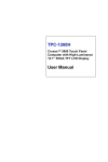
Figure 3.1 The PCM-7230 for SPC-57 Block Diagram
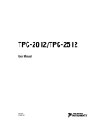
3.1.2 Headers and connectors
This section locates headers and connectors of PCM-7230 and describes their
functionality.
CN3
JP1
CN1
CN8
CN12
CN10, CN11
CN14
J1
CN9
CN18
JP6
JP2
CN20
JP3
JP4
CN29
CN26
CN31
Figure 3.2: Component side of the PCM-7230
31
Figure 3.3: Solder side of the PCM-7230
Table 3.1 Header Description
Label
JP 1
JP 2
JP 3
JP 4
CN 1
CN 3
CN 8
CN 9
CN 12
CN 14
CN 18
CN 20
CN 25
CN 26
CN 29
CN 31
Function
CPLD JTAG port
CPU PXA255 JTAG port
LCD signal voltage level select
Power switch header
PCMCIA accessing status port
multi-function I/O header(I)
CRT-out header
multi-function I/O header(II)
HotKey function header
memory module 100-pin board-to-board connector
TTL level LCD signal connector
LAN status LED header
type II CF slot
Inverter signals header
Power-in connector
SM bus port
32
3.1.3 Headers and connectors pin definition
Because the board size limitation & wants to keep the flexible of I/O connector
placement,
The following lists are I/O pin definitions of PCM-7230 SBC. All the pin headers’
pin order is the same as the figure. As you see, the first pin has a white mark on PCB.
Except the pin headers, all the other connectors have white mark at 1st pin.
1
2
3
4
4
5
6
7
The following tables are the pin definition of all the connectors on PCM-7230
SBC.
★JP 1 : CPLD JTAG port
there are two CPLDs on PCM-7230. Advantech doesn’t suggest users to modify
the CPLD code. If users have to do it, please contact your distributor or sales
representative.
★ JP 2 : CPU PXA255 JTAG port
Pin Number
Pin function
1
TCK
2
TDI
3
TDO
4
TMS
5
nJTAG_TRST
6
nRESET
Note: Users can use this port to modify the bootloader.
33
Ps.
★JP 3 : LCD signal voltage level select
Pin Number
1
Pin function
SYS_VCC
Ps.
+5V
power of LCD-signal
2
LCD_VCC
buffers
+3.3V. VCC3P3 will
3
VCC3P3
change to 0V when
system enter sleep mode.
Note: when User wants to use CN18 (40 pin TTL level LCD signal) to drive LCD
panel, user needs to setup this pin header. If the LCD panel signal is 3.3V then set the
2.00mm jumper at 1-2 pin of JP3; if the LCD panel signal is 5V then set the jumper at
2-3 pin.
★JP 4 : Power switch header
Pin Number
1
Pin function
POW_SW_P
Ps.
connect to power switch
positive pole
2
POW_SW_N
connect to power switch
negative pole
Note: Only pin 1 is shorted with pin 2 of JP4, the system power is on.
★ CN 1 : PCMCIA accessing status port
Pin Number
Pin Function
Ps.
1
Resv.
2
Resv.
3
PCM_RDY
4
PCM_VR
Note: If user wants to know the accessing status of PCMCIA slot, user can directly
connect the LED positive pole to 4th pin and negative pole to 3rd pin.
★ CN 3 : multi-function I/O header (I)
Pin Number
1
2
3
4
5
6
7
8
9
10
11
12
13
14
15
16
Pin Function
Resv.
Resv.
Resv.
Resv.
Resv.
Resv.
DI 0*
DO 0*
DI 1*
DO1*
DI 2*
DO2*
DI 3*
DO3*
DI 4*
DO 4*
Ps.
Digital input bit 0.
Digital output bit 0.
Digital input bit 1.
Digital output bit 1.
Digital input bit 2.
Digital output bit 2.
Digital input bit 3.
Digital output bit 3.
Digital input bit 4.
Digital output bit 4.
34
17
18
19
20
21
22
23
24
25
26
27
28
DI 5*
DO 5*
DI 6*
DO 6*
DI 7*
DO 7*
GND
VCC3P3
Digital input bit 5.
Digital output bit 5.
Digital input bit 6.
Digital output bit 6.
Digital input bit 7.
Digital output bit 7.
positive port of right channel
speaker-out function
negative port of right channel
speaker-out function
positive port of left channel
speaker-out function
negative port of left channel
speaker-out function
SPK_OUT_RP
SPK_OUT_RN
SPK_OUT_LP
SPK_OUT_LN
29
30
31
32
33
34
35
36
37
38
39
40
41
42
43
44
45
46
47
48
LINE_OUT_RP
LINE_OUT_LP
AC97_AGND
AC97_AGND
LINE_IN_L
LINE_IN_R
MIC_IN
AC97_AGND
nUART3_DCD
UART3_RXD
UART3_TXD
nUART3_DTR
GND
nUART3_DSR
nUART3_RTS
nUART3_CTS
nUART3_RI
VCC_UART3
nRESET_OUT
49
50
51
52
53
54
55
56
57
58
nUART2_DCD
UART2_RXD
UART2_TXD
nUART2_DTR
GND
nUART2_DSR
nUART2_RTS
nUART2_CTS
nUART2_RI
VCC_UART2
left channel of audio line-in port
right channel of audio line-in port
audio microphone-in port
+5V
reserved for future use. pull-high by
100K resistor.
MODE
+5V
*Warning! Be careful when these DI/DO are used. Surge or over voltage may damage
35
the circuits.
★ CN 8 : CRT-out header
Pin Number
1
2
3
4
5
6
7
8
Pin function
Reserv.
CRT _Vsync
Reserv.
CRT _Hsync
CRT_B
GND
CRT _G
CRT _R
Ps.
reserve for the future
reserve for the future
CRT blue signal
CRT green signal
CRT red signal
★ CN 9 : multi-function I/O header(II)
Pin Number
1
2
3
4
5
Pin function
TPTX100P
TPTX100N
TPRX100P
TPRX100N
RJ45_P4_P5
6
RJ45_P7_P8
7
8
9
10
11
12
13
14
15
16
17
Resv.
Resv.
Resv.
Resv.
Resv.
Resv.
Resv.
Resv.
Resv.
Resv.
UART4_485_TXN
18
UART4_485_TXP
19
20
21
22
23
24
25
26
27
28
29
Resv.
Resv.
Resv.
Resv.
Resv.
Resv.
Resv.
Resv.
Resv.
Resv.
XP
36
Ps.
Lan TX signal
Lan TX signal
Lan RX signal
Lan RX signal
LAN connector P4 & P5.
in order to avoid noise
LAN connector P7 & P8.
in order to avoid noise
Negative signal of RS485
function.
Positive signal of RS485
function.
X axis positive signal of
30
31
32
33
34
35
36
37
38
39
40
41
42
43
44
45
46
47
48
49
50
51
52
53
54
55
56
57
58
YP
XN
YN
nUART1_DCD
UART1_RXD
UART1_TXD
nUART1_DTR
GND
nUART1_DSR
nUART1_RTS
nUART1_CTS
nUART1_RI
VCC_UART1
GND
VCC_UART1
N.C.
N.C.
USB_VCC5
GND
SA_BUSB_DPR
SA_BUSB_DNR
USB1_V
GND
USB1_P
USB1_N
USB2_V
GND
USB2_P
USB2_N
touch screen function
touch screen signal
touch screen signal
touch screen signal
+5V
No function
No function
USB 1st host power +5V
USB 1st host signal
USB 1st host signal
USB 2ed host power +5V
USB 2ed host signal
USB 2ed host signal
★ CN 12 : HotKey function header
Pin Number
Pin function
Ps.
1
HK 1
1st pin of hotkey function
2
HK 5
5th pin of hotkey function
3
HK 2
2nd pin of hotkey function
4
HK 6
6th pin of hotkey function
5
HK 3
3rd pin of hotkey function
6
HK 7
7th pin of hotkey function
7
HK 4
4th pin of hotkey function
8
HK 8
8th pin of hotkey function
9
GND
10
SYS_VCC3P3
note : when HKx connects to SYS_VCC3P3, then hotkey function works. HKx
signals are triggered by rising edge.
37
★CN 18 : TTL level LCD signal connector
Pin Number
Pin function
1
VCC
2
VCC
3
GND
4
GND
5
VCC3P3
6
VCC3P3
7
LCD_VEE
8
GND
9
LCD_D0
10
LCD_D1
11
LCD_D2
12
LCD_D3
13
LCD_D4
14
LCD_D5
15
LCD_D6
16
LCD_D7
17
LCD_D8
18
LCD_D9
19
LCD_D10
20
LCD_D11
21
LCD_D12
22
LCD_D13
23
LCD_D14
24
LCD_D15
25
LCD_D16
26
LCD_D17
27
LCD_D18
28
LCD_D19
29
LCD_D20
30
LCD_D21
31
LCD_D22
32
LCD_D23
33
GND
34
GND
35
SHCLK
36
FLM_VSYNC
37
M_DE
38
LP_HSYNC
39
N.C.
40
ENVEE
note : User can use JP3 to change the LCD signals level.
38
Ps.
+5V
+5V
+3.3V
+3.3V
no function
★ CN 20 : LAN status LED header
Pin Number
Pin function
Ps.
compact flash slot LED indicator,
1
CF_VR
positive pole
compact flash slot LED indicator,
2
CF_RDY
negative pole
3
LED_LINK_P
positive pole of LAN link status LED
4
LED_LINK_N
negative pole of LAN link status LED
negative pole of LAN 10/100 speed
5
LED_SPEED_P
status LED
negative pole of LAN 10/100 speed
6
LED_SPEED_N
status LED
Note: If user wants to know the accessing status of CF slot, he can connect the LED
positive pole to pin 1 and negative pole to pin 2.
★ CN 26 : Inverter signals header
Pin Number
Pin function
Ps.
1
SYS_VCC
+5V
2
GND
3
ENVBK5V
inverter enable signal
4
BLCTRL_SW
backlight strength switch
5
Resev.
reserve pin for future
6
GND
7
Power_LED
System power LED indicator. +3.3V
8
GND
9
Resev.
reserve pin for future
10
Resev.
reserve pin for future
11
Resev.
reserve pin for future
12
Resev.
reserve pin for future
Note: If user wants to know the system power status by self-connected LED, he can
connect the LED positive pole to pin 7 and negative pole to pin 8.
★CN 29 : Power-in connector
Pin Number
Pin function
Ps.
negative pole of power
1
GND
input
negative pole of power
2
GND
input
DC_IN
positive pole of power
3
input
DC_IN
positive pole of power
4
input
Note: CN29 is the main power input port. The DC_IN range is 10V ~ 28V.
39
★CN 31 : SM bus port
Pin Number
Pin function
1
I2CSCL
2
GND
I2CSDA
3
4
nDC_IN
Ps.
clock pin of SM bus for
smart battery
data pin of SM bus for
smart battery
This pin is pulled low on
PCM-7230 by 2M ohm.
3.1.4 COM1~COM4 serial ports
The PCM-7230 offers four full-functions RS-232 (COM1, COM2, and COM3) and
one RS-485 w/ AFC (COM5) serial communication interface ports.
¾
Automatic Data Flow Control Function for RS-485
The RS-485 in PCM-7230 will automatically sense the direction of incoming data and
switch its transmission direction accordingly. Therefore no handshaking signal (e.g.
RTS signal) is necessary. This feature lets users build an RS-485 network simply and
quickly with just two wires. More importantly, application software previously
written for half duplex RS-232 environments can be maintained without need for
modification.
3.1.5 LAN: Ethernet Connector(CN9,Pin1~Pin6)
The PCM-7230 is equipped with one Davicom DM9000 10/100 Base-T Ethernet
LAN controller. The second and third LED indicators (approach AMI-120 Interface)
on board show the Link and Active (Green LED) status of this Ethernet port.
3.1.6 USB client connector(CN9,Pin47~Pin50)
This USB client connector is used to communicate with PC for ActiveSync. Users
may connect the PCM-7230 with PC to develop their own applications and download
files to PCM-7230.
3.1.7 DC power connector(CN29)
The DC power connector carries 12 VDC external power input and features reversed
wiring protection. Therefore, it will not cause any damage to the system by reversed
wiring of ground line and power line.
3.1.8 LCD display connector(TTL level:CN18 ; LVDS:J1)
This 40-pin LCD display connector is for LCD connectivity.
40
3.1.9 LCD inverter connector for 5V inverter(CN26, Pin1~Pin4)
Connect the PCM-7230 with the 5V inverter for adjusting LCD panel’s brightness.
The voltage range of this signal is from 0 to 5V. When enable backlight is on, the
voltage of this signal is 5V; otherwise is 0V. Brightness voltage is adjustable by
Advantech SW utility.
3.1.10 Audio connector(CN3,P25~P36)
The PCM-7230 provides audio signals on pin25 ~ pin36 of CN3. These audio signals
include Microphone in (mono), Line in/out (stereo) and two speaker-out function.
3.1.11 Battery and DC power status monitor connector(CN31)
With this connector, the PCM-7230 can monitor and report the battery and DC power
status thru I2C bus.
3.1.12 4-wire touch-screen connector(CN9,Pin29~Pin32)
Connect the PCM-7230 with the 4-wire touch-screen. The PCM-7230 supports 4-wire
resistive touch-screen. Figure 3.7 shows the cable connected to this connector.
3.1.13 8 DI,8 DO pin header (CN3,Pin7~Pin24) & GPIO pin header(CN12)
This connector connects the PCM-7230 with the 8 DI & 8 DO. The PCM-7230 has
8-channel digital inputs,8-channel digital outputs and 8 GPIO pins. The GPIO is
default for hotkey function.
3.1.14 PCMCIA slot (U10)
The PCM-7230 default provides one type II hot-swappable PCMCIA slots in the
solder side for CompactFlash card, wireless LAN card, etc.
3.1.15 100-pin board-to-board connector for Memory Module (CN14)
Another issue related to the Memory Module is boot priority. Users may put your
image files into flash on the Memory Module by Advantech upgrade utility. Users
may also put your image files in the CompactFlash card as another choices and boot
from PCMCIA or CF slots. The CompactFlash card always comes the first priority
when system is booting.
41
Figure 3.4: Component Side of Memory Module
Figure 3.5 Solder side of Memory Module
3.1.16 Backup Battery (BT1)
The PCM-7230 series build in one 3.0V, coin-type rechargeable backup battery for
external RTC. This backup battery is charging when system power is on.
42
3.1.17 Form factor
Figure 3.6 Form factor of the PCM-7230
3.2 I/O Board
The I/O Board can expand its I/O function thru two I/O cables. The expand functions
have RS-232*1(COM1); RS-485*1(COM4) ; Audio(Line-out) ; RJ-45 for Ethernet
port ; USB Client ; 2 port USB Host ; Power connector (10~28 V) ; Power switch ;
Power Source to main board ;
Multi-function I/O header (I) ; Multi-function I/O header (II).
43
Figure 3.7 Component side of the I/O Board
PN
Position
Description
1
CN4
COM1 (RS-232) Serial Port
2
CN6
COM4(RS-485) Serial Port
3
CN2
Audio(Line-out) Port
4
CN5
RJ-45 for Ethernet Port
5
CN3
USB Client Port
6
CN1
USB Host Port
7
CN9
Power Connector
8
SW1
Power Switch
9
CN10
Power Source to main board
10
CN7
Multi-function I/O header (I)
★ CN 6 : RS-232 serial port
44
Pin
1
Signal
DCD
2
RXD
3
TXD
4
DTR
5
GND
6
DSR
7
RTS
8
CTS
9
RI
Figure 3.8 I/O Board COM1(RS-232) serial port
★ CN 4 : RS-485 serial port
45
Pin
Signal
1
N/C
2
Data+
3
Data-
4
N/C
5
GND
6
N/C
7
N/C
8
N/C
9
N/C
Figure 3.8 I/O Board COM4(RS-485) serial port
★ CN 2 : Audio (Line-out) port
Pin
Signal
1
Right channel
2
Left channel
3
GND
4
Left channel
Figure 3.9 I/O Board Audio(Line-out) port
★ CN 5 : RJ-45 for Ethernet port
46
Pin
Signal
1
TPTX100P
2
TPTX100N
3
TPRX100P
4
N/C
5
N/C
6
TPRX100N
7
N/C
8
N/C
9
NC
10
NC
11
GND
12
GND
13
LED1+
14
nLINK
15
LED2+
16
nSPEED100
Figure 3.10 I/O Board RJ-45 for Ethernet port
★ CN 3 : USB Client port
47
Pin
Signal
1
USB_VCC5
2
SA_BUSB_DNR
3
SA_BUSB_DPR
4
GND
ripheral Board USB Client port
Figure 3.11 I/O board USB client port
★ CN 1 : USB Host port
Pin
Signal
1
VCC_USB_H1
2
USB_N1
3
USB_P1
4
GND
5
VCC_USB_H2
6
USB_N2
7
USB_P2
8
GND
F
3.12 I/O Board USB Host port
★ CN 9 : Power Connector
48
Pin
Signal
1
19 VDC (+)
2
19 VDC (-)
3
GND
Figure 3.12 I/O Board Power connector
★CN 10 : Power source to Main Board
Pin
Signal
1
GND
2
GND
3
DC in
4
DC in
Figure 3.13 I/O Board Power source to main board
★CN 7 : Multi-function I/O header (I)
49
Pin Number
1
2
3
4
5
6
7
8
9
10
11
12
13
14
15
16
17
18
19
20
Pin function
UART1_RDCD
UART1_RRXD
UART1_RTXD
UART1_RDTR
GND
UART1_RDSR
UART1_RRTS
UART1_RCTS
UART1_RRI
IO_VCC3P3
C950_485_RTXP
C950_485_RTXN
GND
GND
SPK_OUTRP
SPK_OUTLP
USB_VCC5
GND
SA_BUSB_DPR
SA_BUSB_DNR
★CN 8 : Multi-function I/O header (Il)
50
Ps.
Pin Number
1
2
3
4
5
6
7
8
9
10
11
12
13
14
15
16
17
18
19
20
Pin function
AC97_AGND
AC97_AGND
TPRX100N
TPRX100P
TPTX100N
TPTX100P
nSPEED100
nLINK
AC97_AGND
AC97_AGND
IO_VCC3P3
IO_VCC3P3
VCC_USB_H1
VCC_USB_H2
USB_P1
USB_N1
USB_P2
USB_N2
AC97_AGND
AC97_AGND
Ps.
3.3 Power system
The power system of the SPC-57 includes IO board, adapter and power cord.
Users can only use a Terminal Block 5.08mm 3P MALE 19Vdc power adapter to be
SPC-57’s power input. There is one 3.0V, coin-type rechargeable backup battery on
SPC-57. This coin battery is mainly for external RTC of the PCM-7230. When the
power switch is on, the external DC power will automatically charge this coin battery.
51
CHAPTER
4
Software Functionality
This chapter details the Windows®
CE.NET operating system on the
Sections include:
• Introduction
•Windows® CE Startup Procedure
• Upgrade Procedure
• Utilities
• Network
• Intel Persistent Storage Manger
• Application Program Development
• Windows® CE.NET 4.2 Require Components
52
4.1 Introduction
The SPC series is one embedded system with Windows® CE.NET OS. The Windows®
CE.NET is a compact OS that occupies less storage space or system resources
compared with other operating systems such as Windows® NT or Windows® XP. By
its modular nature, it is possible to choose those functions that are useful for specific
application. Not only reducing the system resources required, but also reduces start-up
time. In the field of embedded applications, this is an appealing feature because the
impact of downtime would be minimized.
Furthermore, the small storage space it needs makes OS on solid-state disk possible, which implies
higher robustness to harsh environments.
Figure 4.1 Windows® CE.NET on the SPC Series
4.2 Windows CE Startup Procedure
Windows CE can be loaded by two methods, first is by Compact Flash card, and
second is by on-board flash chip. Compact Flash card is high boot priority than
on-board flash chip. In BOOTLOADER criteria, it will first read the Windows CE
image in Compact Flash card. If Compact Flash card is unavailable or no Windows
CE image inside, BOOTLOADER will load the Windows CE image from on-board
flash chip. BOOTLOADER copy Windows CE image to DRAM and launch WinCE
from DRAM, whenever loaded by Compact Flash card or on-board flash chip.
Therefore, there are some advantages,
1, Easy Windows CE image installation: Customer can copy Windows CE image they
53
want to Compact Flash card, and then load this image by BOOTLOADER.
2, Flexible Hardware design : Flash on board design is unnecessary. The Windows CE
can be loaded by Compact Flash card.
4.3 Upgrade Procedure
After the OS image was built, we may want to burn it to the on-board flash ROM.
Advantech provides the upgrade utility “Upgrade” to upgrade Bootloader image,
WinCE image or boot logo to onboard flash ROM. The upgrade procedure is
described as following :
Step1. Copy “Upgrade” utility and image files you want (for example, NK.NB0,
EBOOT.NB0, and WINDOWSCE.BMP ) to CF storage card.
Note : NK.NB0 is WinCE image.
EBOOT.NB0 is Bootloader image.
WINDOWSCE.BMP is boot bitmap.
Step2. Insert CF storage card to platform, and then launch Upgrade.exe.
Figure 4.2 Image files and upgrade utility in CF storage card
Step3. Check the items you want to upgrade as the figure shown below. If you want to
upgrade boot logo, you can input the path of the bitmap file in the edit box or click
‘Browse’ button to select the file.
54
Figure 4.3 Upgrade utility
Note: The difference between NK.NB0 (Compressed) and NK.NB0 (Normal, XIP) :
The option “NK.NB0 (Normal, XIP)” means that the nk.nb0 will be upgraded directly
to the flash ROM, and “NK.NB0 (Compressed)” means that we compress nk.nb0 first,
and then write the compressed data to the flash ROM. :
(1) Boot time : compressed image take more time in system bootup.
(2) IPSM size : compressed OS image would result in larger IPSM size.
Step4. Press ‘Apply’ button on the dialog. Then the items you select will be upgraded
to the flash ROM. See Figure 4-4.
Figure 4.4 Press Apply button in order to upgrade onboard flash ROM
After the upgrade process done, to power off platform and power on it. On the first
time boot, it will take about 1 minute to format the IPSM.
4.4 Utilities
There are several useful utilities added in the standard Windows® CE.NET OS:
4.4.1 Regflash
The utility "Regflash" is a convenient tool to save, overwrite or delete registry data, as
well as erase the content of IPSM folder. From the Windows® CE.NET status bar, tap
"Start/Run". Use the soft-keyboard to type "regflash" command in the command text
box and press "OK". There are four selections here:
Save to Flash, Delete from Flash, Save to CF Disk, Erase IPSM.
Choose the options you want and press "Save" button to proceed. "Save to Flash"
option was used to save the registry setting to on board flash ROM. In contrast,
"Delete from Flash" option was intended to erase the on board registry data. "Save to
CF Disk" option would save the registry data to CompactFlash card as a file
"wince.reg". "Erase IPSM" option erase the IPSM region of the on board flash.
Note: Please be careful using this utility "Regflash". This utility is able to overwrite
all registry data.
55
Figure 4.5 Regflash utility
It is important to keep the power normal during "Save to Flash" process. If the power
were broken down during the registry saving process, then the registry would be lost
and corrupted. On the next time you turn on platform, the system would load the
default registry setting rather than the previously customized registry setting.
4.4.2 Reboot
The utility "Reboot" is a convenient tool to reset the system. From the Windows®
CE.NET status bar, tap "Start/Run". Use the soft-keyboard to input "reboot" command
in the command text box and press "OK". The other ways to reboot are clicking the
“Reboot” button on the Watchdog page of the built-in utility System Configurator and
hardware reboot button.
Figure 4.6 Reboot the system
4.4.3 Startup execution
The SPC has one useful function call "Startup execution". After the system boot up,
the startup execution function would automatically perform. This function is useful
for control system to do the initialization processes or some other procedures. In SPC,
56
there are two ways to perform "Starup" function.
Method 1:
Step1: Create "startup" directory in CF storage card or in folder "\IPSM\".
Step2: Copy executable files to "startup" directory that is created by Step 1.
Example:
We copy two executable files "REGFLASH.exe" and "Notepad.exe" in
"\IPSM\Startup", and then reboot the system. After the system boot up, the two
executable files would automatically execute.
Method 2:
Step1: The same as Step1 in Method 1.
Step2: Create a file called "startup.ini" in "startup" directory. Type in the commands
you want to execute after boot up in that file.
Example:
Create "Startup.ini" in "\IPSM\Startup" directory and reboot the system. The content
of startup.ini was listed below:
\windows\tty.exe
\windows\registry.exe
After the system reboot, "\windows\ tty.exe" and "\windows\ registry.exe" would
automatically execute. Be sure that the two methods are independent. It means they
can be used simultaneously.
4.4.4 Safemode
SPC allow user to alter registry setting, and save it by either "regflash.exe" or the
registry frame of the “Misc” page of the System Configurator. But sometimes user
may make some non-appropriate registry setting, and cause SPC fail to boot. In the
circumstance, the easiest way to boot up SPC is to use the default registry setting from
the Windows® CE.NET image. When the SPC is booted up with the default registry
setting, we say that it is working in "safemode". To enter "safemode", user must
perform several steps as described below:
Step 1: Create a file whose filename is "safemode" or a folder whose name is
"safemode" in the CompactFlash card.
Step 2: Insert the CompactFlash card into the SPC series platform.
Step 3: Turn on the power switch of SPC series platform.
57
4.4.5 System Configurator
System Configurator is an outstanding utility designed by Advantech Windows®
CE.NET software team. It is an integrated environment where user can get useful
system information as well as configure favorite system settings and apply system
control function on demand. Double click the icon of System Configurator on the
desktop. Following sections illustrate the functions of System Configurator.
4.4.5.1 General
The memory information including DRAM, CF Disk and IPSM FLASH are displayed
in the General page. And the versions of each part of the installed embedded OS,
including Windows® CE.NET, Registry, Bootloader and System Configurator
respectively.
Figure 4.7 General information
4.4.5.2 Calibration
The Touch-screen page provides the calibration function. Click the "calibration"
button, the "Stylus Properties" windows would appear. Then click "calibrate" button
in the Stylus Properties window to enter calibration process. In the calibration process,
user taps on the center of the target on the screen then the target will move to the next
position. After calibration, press "OK" to leave Stylus Properties window, and then
the Regflash utility process would automatically start to save the registry setting.
58
Figure 4.8 Touch-screen calibration
4.4.5.3 Display
From time to time it is unnecessary to turn on the display attached to the SPC all the
day. The Display page provides several frequently used functions such as turning off
the LCD and backlight to elongate the display repair period, adjusting brightness or
contrast. For example, if user wants the backlight turn-off setting function, he can
press "setting" button. Then the backlight page of Display Properties of Control Panel
will appear on the screen. Besides, user can click the "Off Now" button to turn off the
backlight of the display panel immediately without waiting. Once the backlight was
turned off, there were three inputs to turn it on: (1) mouse; (2) keyboard; (3)
touch-screen; user can use any one of them to turn on the display. The lower
“Brightness” and “Contrast” blocks have scroll bars by which users can tune
brightness level of TFT LCD or the contrast level of passive matrix LCD.
Figure 4.9 Display configuration
59
4.4.5.4 WatchDog timer
It is important in industrial applications that the control systems are rarely crashed, or
are capable of self-reset if they are halted somehow. Watchdog function of automatic
resetting system is therefore provided in SPC. There is a timer inside the watchdog
function. User’s AP could invoke the associated APIs in Watchdog function to start
the timer, then Watchdog function would repeat the countdown of the specified period
of time to reboot the system if the user’s AP does not clear the timer in time
periodically. The Watchdog function in the SPC provides eight different time
intervals: 2 seconds, 5 seconds, 10 seconds, 30 seconds, 60 seconds, 2 minutes, 5
minutes and 10 minutes. The “Enable" button is used to simulate the Watchdog
function. Detail programming guide is illustrated at section 4.7.5. The “Sleep” button
could make the system enter suspend mode as “Suspend” of “Start” could. Press the
"SoftReset" button will cause system warm boot that clears DRAM, reloads all drivers
and refresh the newest registry settings. Press the “REBOOT” button will cause the
system cold boot.
Figure 4.10 Watchdog timer
4.4.5.5 Hotkeys
There are 8 Hotkeys reserved for users on the SPC. These Hotkeys are
assigned to invoke different application programs as defaults:
Hot key 1: invokes Windows Explorer
Hot key 2: invokes Advantech homepage
Hot key 3: invokes System Configurator
Hot key 4: invokes Windows Media Player
Hot key 5: invokes Control Panel
Hot key 6: invokes Command prompt
Hot key 7: invokes Calibration dialog
Hot key 8: invokes repllog.exe
60
These settings can be freely revised by keying in new paths in the edit boxes.
Figure 4.11 Hotkeys setting
4.4.5.6 DIO
There are 8 digital inputs and 8 digital outputs. This DIO page of the System
Configurator can show their status. When the “Start” button is pressed, the 8
DI will try to retrieve external inputs, then those pins having positive inputs will
mark respective radial buttons inside the “Digital Input Status” block, others will
make their radial buttons empty. On the other hand, when users use mouse,
finger or stylus to check some of the 8 check boxes, the level of the related DO
pins will be changed to positive level. The DO pin status will sustain until users
change them again.
Figure 4.12 DIO setting
61
4.4.5.7 Miscellaneous
The Misc page provides several functions as described below. The "Registry" block
provides registry save and registry view function. The “A. Sync” button invokes
ActiveSync to the host computer. ”The "HTTP Server Root" block was used to
specify the root directory of http server. The default directory is
"\windows\www\wwwpub", user can specify another directory by type the directory
in the edit box and press "Set" button. The new setting would become effective after
the system reboot. The “CF Disk Folder Name” block specifies the folder name of the
storage card inserted. The default name is “Storage Card”. User can specify another
directory by type the directory in the edit box and press "Set" button. The new setting
would become effective after the system reboot. The "MAC ID" block shows the
network MAC address. The "COMM" block provides the communication functions,
including IPConfig and Pinging Yahoo.
Figure 4.13 Miscellaneous settings
62
4.5 Network
4.5.1 Networking via Ethernet
SPC build in one 100Base-T Ethernet controller. It appears at “Control Panel/Network
and Dial-up Connections” via “DM9CE1”. User can configure its Ethernet support as
follows:
1. Click "Start/Settings/Control Panel"
2. Double click "Network and Dial-up Connections"
3. This window will display all available connections. Pressing the connection icon,
its pop-up menu appears and users could disable, rename or modify properties
from there.
4. If the SPC is a node of the LAN with DHCP servers, it is now available.
5. If the SPC is a node of the LAN with fixed IP, the user has to consult with MIS to
get specific IP addresses. Then fill them into the associated fields of the Properties
Dialog that could be popped up by the properties item of the step 3 above. Then
use the "Regflash" utility to save this changed registry. Reboot the system, the
Ethernet functions would be available as previous configuration.
Figure 4.14 Networking via Ethernet
4.5.2 Networking via USB port
The SPC supports USB port direct-connections to host computer. The host computer
must install the Microsoft ActiveSync service offered by Microsoft. Use the USB
cable to connect the USB ports of them. Then activate ActiveSync service on the host
computer. The host will automatically scan the USB ports to make a connection.
1. Make sure the Microsoft ActiveSync service and the Microsoft embedded Visual
Tools are properly installed in the host PC.
63
2. Connect the USB port of the host PC and the SPC by a USB ActiveSync cable.
3. If users are using the Microsoft eMbedded Visual Tools to develop Windows®
CE.NET application runtimes, make sure the SPC SDK provided in the SPC
support CD is also properly installed in the host PC.
4. Click "Start/Settings/Network and Dial-up Connections"
5. Make a new connection. As the dialogue box pops out, choose the default "Direct
Connection" radial button. Click "Next".
6. Select "USB Cable" from the combo box and click "Finish" to complete making
new connection. It is recommended to keep the default settings of the ports
connection.
7. Click “PC Connection” icon in the Control Panel. As the “PC Connection
Properties” dialogue box pops up, change the connection to the newly made
connection by clicking the “Change...” button.
8. If the ActiveSync service on the host PC has been activated, the above seven steps
will make the SPC automatically try to connect the host, ;otherwise you can invoke
"\windows\repllog.exe" to do the activesync connection.
NOTE: Users should properly install the associated USB driver on the host computer
while plugging in the SPC as a USB client device at the first time.
NOTE: The USB driver--wceusbsh.inf and wceusbsh.sys--are included in SPC support
CD.
NOTE: Users may also use COM ports to do ActiveSync function thru RS-232 cable.
64
Figure 4.15 Networking via USB port
4.5.3 Networking via PPP
The SPC supports PPP protocol. To setup and utilize it, follow the steps below:
1. Click "Start/Settings/Network and Dial-up Connections”
2. Make a new connection. As the dialogue box pops out, choose the "Dial-Up
Connection". Click "Next".
3. Click "Configure" to setup the device according to the specification of your modem,
and then click "OK" on the top-right corner of the window.
4. Click "Next". Input the telephone number in the "Phone Number" window. Press
"Finish" to complete the setup process.
5. Turn on your modem and use RS-232 cable to connect modem and COM1 of SPC
series.
6. Double click the connection you have made in Step 4. Key in the user name,
password and domain for the dial-up connection and press "Connect".
65
Figure 4.16 Networking via PPP
4.5.4 Web browser
The SPC builds-in Windows CE OS includes IE Browser. It can be used to browse
web pages on World Wide Web via LAN or PPP.
66
4.6 Intel Persistent Storage Manger (IPSM)
4.6.1 Introduction to Intel Persistent Storage Manger
Intel Persistent Storage Manager was designed and developed specifically as an
enhancement to Microsoft Windows CE operating systems. IPSM eliminates extra
disk-like storage such as storage cards, redundant RAM and ROM.
4.6.2 IPSM folder in SPC Series
SPC uses Intel Persistent Storage Manger to utilize the free space of flash ROM for
persistent storage. The IPSM region in the system is located in "\IPSM" directory.
Any file or directory stored in "\IPSM" directory would be keep persistently, even if
the power of SPC were turned off. The user can store software or data in \IPSM rather
in CF card to avoid inconvenience.
67
4.7 Application Program Development
The SPC is bundled with built-in Windows® CE.NET operating system. In real
application user need to execute various application programs on it. However, unlike
its other CPU family, the Windows® CE.NET is a hardware-dependent operating
system. That is to say, Windows® CE.NET application programs are only portable in
the source code level. Users must rebuild the runtime file for a different Windows®
CE.NET platform even though the source code may not be changed at all.
4.7.1 System requirements
• Intel® Pentium-90 CPU or more advanced
• Microsoft® Windows® 2000 Professional or Windows® XP
• Microsoft® eMbedded Visual Tools 4.0
• Platform SDK for SPC
• 64MB DRAM
• CD-ROM drive
• Monitor with VGA resolution at least
• Mouse
• 200MB free hard disk space at least
• SPC series platform
• Let the host PC and SPC connect on the same LAN to do kernel debugging if
necessary
• USB cable (bundled in the standard SPC series)
4.7.2 Building Windows CE program
By the platform SDK bundled with the standard SPC, users can build the Windows
CE runtime application program by the eMbedded Visual Tools.
68
Figure 4.17 Flow-chart of Building Windows® CE.NET runtime
4.7.3 How to install SDK
Copy SPC SDK file “SOM_A_SDK.msi” to your PC, and launch it. You can install
SDK by steps.
Step 1, Launch SPC SDK file, and then tap Next button.
Figure 4.18
69
Step 2, Accept License Agreement and go next.
Figure 4.19
Step 3, Key in your information and go next.
70
Figure 4.20
Step 4, Choose setup type.
There are 3 options “Embedded Visual C++”, “Microsoft .NET Compact Framework”,
and “Documentation” in Custom Setup.
Figure 4.21
71
Figure 4.22
Step 5, Tap “Install” button to install SDK.
Figure 4.23
72
Install SDK…….
Figure 4.24
Step6, Finish installing.
73
Figure 4.25
4.7.4 Running your application programs
ActiveSync would automatically transfer the built application program to platform.
Choose SDK type as SOM_A once compile your application program.
Figure 4.26
4.7.5 WDT Modules
SPC is targeted to be the embedded device for web-enabled and data-acquisition
systems. It is built-in with a useful dynamic link library, WATCHDOG.DLL, which
has been designed to help AP developer easily implement his requirements of
handling the system resources such as Watchdog timer and LCD brightness control
etc. Programmers who are familiar with WIN32 API programming would feel very
easy to use this DLL to create his functions. The DLL make its device services look as
a file whose name is "WDT1:". The programmer could use this file name in
"CreateFile()" to open it and get the file handler. Then the following controls of user
required device services would be achieved by way of the file handler in one function
call of "DeviceIOControl()". At most 5 applications can access watchdog timer
simultaneously. The DeviceIOControl function is following:
- DeviceIoControl
74
This function sends a control code directly to a specified device driver, causing the
corresponding device to perform the specified operation.
BOOL DeviceIoControl(
HANDLE hDevice,
DWORD dwIoControlCode,
LPVOID lpInBuffer,
DWORD nInBufferSize,
LPVOID lpOutBuffer,
DWORD nOutBufferSize,
LPDWORD lpBytesReturned,
LPOVERLAPPED lpOverlapped);
- Parameters
hDevice
[in] Handle to the device that is to perform the operation. Call the Create- File function to obtain a
device handle.
dwIoControlCode
[in] Specifies the control code for the operation. This value identifies the specific operation to be
performed and the type of device on which the operation is to be performed. No specific values are
defined for the dwIo- ControlCode parameter. However, the writer of a custom device driver can define
IOCTL_XXXX control codes, per the CTL_CODE macro.
These control codes can then be advertised, and an application can use these control codes with
DeviceIoControl to perform the driver-specific functions.
lpInBuffer
[in] Long pointer to a buffer that contains the data required to perform the operation.
This parameter can be NULL if the dwIoControlCode parameter specifies an operation that does not
require input data.
nInBufferSize
[in] Size, in bytes, of the buffer pointed to by lpInBuffer.
lpOutBuffer
[out] Long pointer to a buffer that receives the operation's output data.
75
This parameter can be NULL if the dwIoControlCode parameter specifies an operation that does not
produce output data.
nOutBufferSize
[in] Size, in bytes, of the buffer pointed to by lpOutBuffer.
lpBytesReturned
[out] Long pointer to a variable that receives the size, in bytes, of the data stored into the buffer
pointed to by lpOutBuffer.
The lpBytesReturned parameter cannot be NULL. Even when an operation produces no output data,
and lpOutBuffer can be NULL, the Device-IoControl function makes use of the variable pointed to by
lpBytesReturned. After such an operation, the value of the variable is without meaning.
lpOverlapped
[in] Ignored; set to NULL.
- Return Values
Nonzero indicates success. Zero indicates failure. To get extended error information, call GetLastError.
WDT Control Codes
There are 8 control codes for the operation codes in the WDT1 driver:
1. IOCTL_ENABLE_WDT (0x1001):
Enables the Watchdog timer on your application. Your application must trigger to Watchdog timer by
IOCTL_ACCESS_WDT interface during specified period, otherwise the device will reboot
automatically
lpInBuffer : unsed.
nInBufferSize: unused.
lpOutBuffer: unused.
nOutBufferSize: unused.
2. IOCTL_DISABLE_WDT (0x1002):
Disable the Watchdog time on your application.
lpInBuffer : unsed.
76
nInBufferSize: unused.
lpOutBuffer: unused.
nOutBufferSize: unused.
3. IOCTL_GET_WDTPERIOD (0x1003):
lpInBuffer :unused.
nInBufferSize: unused.
lpOutBuffer: the DWORD pointer to your Watchdog time setting. The unit is mini-second. Its value
should be greater 1000. The default setting is 5000 mini-seconds.
nOutBufferSize: unused.
4. IOCTL_SET_WDTPERIOD (0x1004):
lpInBuffer : the DWORD pointer to your Watchdog time setting. Its value should be greater 1000. The
unit is mini-second. If your application opens the WDT driver, the default Watchdog timer is set to
5000 mini-seconds.
nInBufferSize:.unused.
lpOutBuffer: unused.
nOutBufferSize: unused.
5. IOCTL_ACCESS_WDT (0x1005):
Your application must trigger the Watchdog once during your Watchdog timer period. If your
application has not trigger at the specified period, the device will reboot automatically.
lpInBuffer :unused.
nInBufferSize:.unused.
lpOutBuffer: unused.
nOutBufferSize: unused.
6. IOCTL_GET_SCREENOFFTIME (0x1006):
lpInBuffer :unused.
nInBufferSize: unused.
77
lpOutBuffer: the DWORD pointer to your screen off time if user-interface idled. The unit is
mini-second. If the value is 0, screen-off function is disabled.
nOutBufferSize: unused.
7. IOCTL_SET_SCREENOFFTIME (0x1007):
lpInBuffer : the DWORD pointer to your screen off time if user-interface idled. The unit is mini-second.
If the value is 0, screen-off function is disabled.
nInBufferSize:unused.
lpOutBuffer: unused.
nOutBufferSize: unused.
8. IOCTL_SET_SCREENOFF (0x1010):
Set the LCD power off immediately.
lpInBuffer : unused.
nInBufferSize:.unused.
lpOutBuffer: unused.
nOutBufferSize: unused.
Examples:
#define IOCTL_ENABLE_WDT
0x1001
#define IOCTL_DISABLE_WDT
0x1002
#define IOCTL_GET_WDTPERIOD
0x1003
#define IOCTL_SET_WDTPERIOD
0x1004
#define IOCTL_ACCESS_WDT
0x1005
#define IOCTL_GET_SCREENOFFTIME
0x1006
#define IOCTL_SET_SCREENOFFTIME
0x1007
#define IOCTL_SET_SCREENON
0x100F
#define IOCTL_SET_SCREENOFF
0x1010
78
HANDLE m_hWDT=NULL;
TCHAR szClassName[60];
...
// assign the WDT driver name
wsprintf(szClassName, TEXT("WDT1:"));
// Open the WDT driver
m_hWDT = CreateFile(szClassName, GENERIC_READ | GENERIC_WRITE, 0,
NULL, OPEN_EXISTING, FILE_ATTRIBUTE_NORMAL, NULL);
if ( m_hWDT == INVALID_HANDLE_VALUE )
{
DebugMsg(CString("WDT driver fail"));
return;
}
...
DWORD dwTemp;
DWORD nPeriod=10000;
// Set the Watchdog Timer as 10 seconds (10000 mini-seconds)
DeviceIoControl(m_hWDT, IOCTL_SET_WDTPERIOD, &nPeriod, 4, NULL, 0, &dwTemp, NULL);
// Enable the Watchdog timer
DeviceIoControl(m_hWDT, IOCTL_ENABLE_WDT, NULL, NULL, NULL, 0, &dwTemp, NULL);
While (1)
{
// do your job here...
Sleep(8000);
DeviceIoControl(m_hWDT, IOCTL_ACCESS_WDT, NULL, NULL, NULL, 0, &dwTemp, NULL);
}
DeviceIoControl(m_hWDT, IOCTL_DISABLE_WDT, NULL, NULL, NULL, 0, NULL, NULL);
CloseHandle(m_hWDT);
79
4.8 Windows® CE.NET 4.2 Require Components
(Advantech Recommend)
Applications and Services Development (■: with; □: without)
Feature
Active Template Library (ATL)
C Libraries & Runtimes
Component Services (COM)
Device Management
Lightweight Directory Access Protocol (LDAP)
Message Queuing (MSMQ)
Microsoft Foundation Classes (MFC)
Object Exchange Protocol (OBEX)
Pocket Outlook Object Model (POOM) API
Simple Object Access Protocol (SOAP) Toolkit
Standard SDK for Windows CE .NET
.NET Compact Framework
XML
Default Selection
■
■
■
■
■
■
■
■
□
■
■
■
■
Applications – End User
Feature
ActiveSync
File Viewers
Help
Inbox
Remote Desktop Connection
Terminal Emulator
Windows Messenger
WordPad
Default Selection
■
■
■
□
■
■
□
□
Core OS Services
Feature
Serial Port Support
Parallel Port Support
USB Host Support
Debugging Tools
Power Management
Default Selection
■
■
■
■
■
80
■
Kernel Features
Communication Services and Networking
Feature
Networking Features
Networking - Local Area Network (LAN)
Networking - Personal Area Network (PAN)
Networking - Wide Area Network (WAN)
Servers (HTTPD)
Default Selection
■
■
■
■
■
File Systems and Data Store
Feature
Storage Manager
File & Database Replication (Bit-based)
File System – Internal (RAM & ROM File System)
Registry Storage (RAM-based Registry)
Default Selection
■
■
■
■
Fonts
Default Selection
Feature
Arial
Comic Sans MS
Courier New
Georgia
Impact
Kino
MSLogo
Symbol
Tahoma
Times New Roman
Trebuchet MS
Verdana
Webdings
Wingding
□
□
□
□
□
□
□
□
□
□
□
□
□
□
International
Default Selection
Feature
Locale Services
■
81
Locale Specific Support (Input Method Selector Sample
Application)
Multilingual User Interface (MUI)
■
■
Internet Client Services
Default Selection
Feature
Browser Application (Internet Explorer 5.5 for Windows CE ■
Standard Components)
Internet Explorer 5.5 for Windows CE Components
■
- Internet Explorer Browser Control Host
■
- Internet Explorer HTML/DHTML API
■
- Internet Explorer Multiple-Language API
□
- Internet Explorer TV-Style Navigation
■
- URL Moniker Services
■
- Windows Internet Services
■
Pocket Internet Explorer HTML View (WEBVIEW)
■
Sample IE 5.5 Internet Options Control Panel
■
Scripting
Multimedia Technologies
Feature
Basic Multimedia
Multimedia Components
- Audio
- DirectMusic
- Digital Rights Management
- Direct3D
- DirectDraw
- DirectShow
- DVD-Video
- Windows Media Player
- Windows Media Technologies
Default Selection
■
■
■
□
□
■
■
□
■
■
Security
Default Selection
Feature
□
Authentication Services (SSPI)
Cryptography Services (CryptoAPI 1.0) with High Encryption
□
Provider
82
Shell and User Interface
Default Selection
Feature
Shell
User Interface
- Accessibility
- Customizable UI
- Mouse
- Touch Display (Stylus)
- Network User Interface
- Overlapping Menus
- Software Input Panel
- Speech Interface
■
■
■
■
■
■
■
■
■
■
83
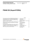
Appendix A Boot & Registry Searching Sequence
The following diagram demonstrates the boot sequence and registry searching sequence when SPC
boot-up.
Power On
SAFEMODE*1
No
Registry on CF
No
Yes
Yes
Image on
Flash Memory
No
Image on
CompactFlash
Image on
CompactFlash
Image on
CompactFlash
No
No
Image on
Flash Memory
Image on
Flash Memory
No
No
Yes
Yes
Yes
Registry on
Flash Memory
Yes
Boot Failure*2
Boot Failure
Yes
Yes
Yes
Boot by Default
Registry
Boot by Registry
on CF
Boot Success
Boot Success
Figure A: Boot & Registry Searching Sequence
84
Boot by Registry
on Flash Memory
No
85