1
Advanced
Digital Motor
Controllers
User Manual
Brushed DC: HDC24xx, VDC24xx, MDC22xx, LDC22xx, LDC14xx,
SDC1130, SDC21xx
Brushless DC: HBL16xx, VBL16xx, HBL23xx, VBL23xx, LBL13xx,
MBL16xx, SBL13xx
Sepex: VSX18xx
v1.3, September 1, 2013
visit www.roboteq.com to download the latest revision of this manual
©Copyright 2013 Roboteq, Inc
Advanced Digital Motor Controllers User Manual
1
Revision History
Date
Version
September 1, 2013
1.3
Changes
Extended command set and CANopen Object Dictionary
Implemented FIFO buffer for CAN frames in the RawCAN mode
Miscellaneous corrections
May 10, 2012
1.2
Added CAN Networking
Added Closed Loop Count Position mode,
Closed Loop Torque mode
Extended command set
January 8, 2011
1.2
Added Brushless Motor Connections and Operation
July 15, 2010
1.2
Extended command set
Improved position mode
May 15, 2010
1.1
Added Scripting
January 1, 2010
1.0
Initial release
The information contained in this manual is believed to be accurate and reliable. However,
it may contain errors that were not noticed at time of publication. Users are expected to
perform their own product validation and not rely solely on data contained in this manual.
2
Advanced Digital Motor Controllers User Manual
Version 1.3. September 1, 2013
Revision History . . . . . . . . . . . . . . . . . . . . . . . . . . . . . . . . . . . . . . . . . . . . . . 2
Introduction . . . . . . . . . . . . . . . . . . . . . . . . . . . . . . . . . . . . . . . . . . . . . . . . . .17
Refer to the Datasheet for Hardware-Specific Issues . . . . . . . . . . . . . . . . . .17
User Manual Structure and Use . . . . . . . . . . . . . . . . . . . . . . . . . . . . . . . . . .17
SECTION 1 Connecting Power and Motors to the Controller . . . . . . . . .17
SECTION 2 Safety Recommendations . . . . . . . . . . . . . . . . . . . . . . . . . .17
SECTION 3 Connecting Sensors and Actuators to Input/Outputs . . . . .17
SECTION 4 Command Modes . . . . . . . . . . . . . . . . . . . . . . . . . . . . . . . 18
SECTION 5 I/O Configuration and Operation . . . . . . . . . . . . . . . . . . . . 18
SECTION 6 Motor Operating Features and Options . . . . . . . . . . . . . . . 18
SECTION 7 Brushless Motor Connections and Operation . . . . . . . . . . 18
SECTION 8 Closed Loop Speed Mode . . . . . . . . . . . . . . . . . . . . . . . . . 18
SECTION 9 Closed Loop Relative and Tracking Position Modes . . . . . . 18
SECTION 10 Closed Loop Count Position Mode. . . . . . . . . . . . . . . . . . 18
SECTION 11 Closed Loop Torque Mode . . . . . . . . . . . . . . . . . . . . . . . . 18
SECTION 12 Serial (RS232/USB) Operation . . . . . . . . . . . . . . . . . . . . . 18
SECTION 13 CAN Networking on Roboteq Controllers . . . . . . . . . . . . 19
SECTION 14 CANopen Interface. . . . . . . . . . . . . . . . . . . . . . . . . . . . . . 19
SECTION 15 MicroBasic Scripting . . . . . . . . . . . . . . . . . . . . . . . . . . . . 19
SECTION 16 Commands Reference . . . . . . . . . . . . . . . . . . . . . . . . . . . 19
SECTION 17 Using the Roborun Configuration Utility. . . . . . . . . . . . . . 19
SECTION 1
Connecting Power and Motors to the Controller. . . . . . . . . . . . . . . . . . . . . 21
Power Connections . . . . . . . . . . . . . . . . . . . . . . . . . . . . . . . . . . . . . . . . . . . 21
Controller Power . . . . . . . . . . . . . . . . . . . . . . . . . . . . . . . . . . . . . . . . . . . . . 22
Controller Powering Schemes . . . . . . . . . . . . . . . . . . . . . . . . . . . . . . . . . . .
Mandatory Connections . . . . . . . . . . . . . . . . . . . . . . . . . . . . . . . . . . . .
Connection for Safe Operation with Discharged Batteries (note 1). . . .
Use precharge Resistor to prevent switch arcing (note 2) . . . . . . . . . .
Protection against Damage due to Regeneration (notes 3 and 4). . . . .
Connect Case to Earth if connecting AC equipment (note 5) . . . . . . . .
Avoid Ground loops when connecting I/O devices (note 6) . . . . . . . . .
24
24
25
25
25
25
26
Connecting the Motors . . . . . . . . . . . . . . . . . . . . . . . . . . . . . . . . . . . . . . . . 26
Single Channel Operation . . . . . . . . . . . . . . . . . . . . . . . . . . . . . . . . . . . . . . 27
Power Fuses . . . . . . . . . . . . . . . . . . . . . . . . . . . . . . . . . . . . . . . . . . . . . . . . 27
Wire Length Limits . . . . . . . . . . . . . . . . . . . . . . . . . . . . . . . . . . . . . . . . . . . 28
Electrical Noise Reduction Techniques . . . . . . . . . . . . . . . . . . . . . . . . . . . . 28
Battery Current vs. Motor Current. . . . . . . . . . . . . . . . . . . . . . . . . . . . . . . . 28
Power Regeneration Considerations . . . . . . . . . . . . . . . . . . . . . . . . . . . . . . 30
Using the Controller with a Power Supply. . . . . . . . . . . . . . . . . . . . . . . . . . 30
SECTION 2
Safety Recommendations . . . . . . . . . . . . . . . . . . . . . . . . . . . . . . . . . . . . . . 33
Possible Failure Causes . . . . . . . . . . . . . . . . . . . . . . . . . . . . . . . . . . . . . . . . 33
Advanced Digital Motor Controllers User Manual
3
Motor Deactivation in Normal Operation . . . . . . . . . . . . . . . . . . . . . . . . . . . 34
Motor Deactivation in Case of Output Stage Hardware Failure . . . . . . . . . . 34
Manual Emergency Power Disconnect . . . . . . . . . . . . . . . . . . . . . . . . . . . . 36
Remote Emergency Power Disconnect . . . . . . . . . . . . . . . . . . . . . . . . . . . . 37
Protection using Supervisory Microcomputer . . . . . . . . . . . . . . . . . . . . . . . 37
Self Protection against Power Stage Failure . . . . . . . . . . . . . . . . . . . . . . . . 38
SECTION 3
Connecting Sensors and Actuators to Input/Outputs . . . . . . . . . . . . . . . . . 41
Controller Connections . . . . . . . . . . . . . . . . . . . . . . . . . . . . . . . . . . . . . . . . 41
Controller’s Inputs and Outputs . . . . . . . . . . . . . . . . . . . . . . . . . . . . . . . . . . 42
Connecting devices to Digital Outputs . . . . . . . . . . . . . . . . . . . . . . . . . . . .
Connecting Resistive Loads to Outputs . . . . . . . . . . . . . . . . . . . . . . . .
Connecting Inductive loads to Outputs . . . . . . . . . . . . . . . . . . . . . . . . .
Connecting Switches or Devices to Inputs shared with Outputs . . . . .
43
43
43
44
Connecting Switches or Devices to direct Digital Inputs . . . . . . . . . . . . . . . 44
Connecting a Voltage Source to Analog Inputs . . . . . . . . . . . . . . . . . . . . . . 45
Connecting Potentiometers to Analog Inputs . . . . . . . . . . . . . . . . . . . . 46
Connecting Potentiometers for Commands with Safety band guards. . 46
Connecting Tachometer to Analog Inputs . . . . . . . . . . . . . . . . . . . . . . . . . . 47
Connecting External Thermistor to Analog Inputs . . . . . . . . . . . . . . . . . . . . 48
Using the Analog Inputs to Monitor External Voltages . . . . . . . . . . . . . . . . 50
Connecting Sensors to Pulse Inputs . . . . . . . . . . . . . . . . . . . . . . . . . . . . . . 50
Connecting to RC Radios . . . . . . . . . . . . . . . . . . . . . . . . . . . . . . . . . . . . 50
Connecting to PWM Joysticks and Position Sensors . . . . . . . . . . . . . . 51
Connecting Optical Encoders. . . . . . . . . . . . . . . . . . . . . . . . . . . . . . . . . . . . 51
Optical Incremental Encoders Overview . . . . . . . . . . . . . . . . . . . . . . . . 51
Recommended Encoder Types . . . . . . . . . . . . . . . . . . . . . . . . . . . . . . . 52
Connecting the Encoder . . . . . . . . . . . . . . . . . . . . . . . . . . . . . . . . . . . . . . . 53
Cable Length and Noise Considerations . . . . . . . . . . . . . . . . . . . . . . . . 53
Motor - Encoder Polarity Matching . . . . . . . . . . . . . . . . . . . . . . . . . . . . 54
SECTION 4
Command Modes . . . . . . . . . . . . . . . . . . . . . . . . . . . . . . . . . . . . . . . . . . . . 55
Input Command Modes and Priorities . . . . . . . . . . . . . . . . . . . . . . . . . . . . .
USB vs Serial Communication Arbitration . . . . . . . . . . . . . . . . . . . . . . .
CAN Commands Arbitration . . . . . . . . . . . . . . . . . . . . . . . . . . . . . . . . .
Commands issued from MicroBasic scripts . . . . . . . . . . . . . . . . . . . . .
55
57
57
57
Operating the Controller in RC mode. . . . . . . . . . . . . . . . . . . . . . . . . . . . . .
Input RC Channel Selection . . . . . . . . . . . . . . . . . . . . . . . . . . . . . . . . . .
Input RC Channel Configuration . . . . . . . . . . . . . . . . . . . . . . . . . . . . . .
Automatic Joystick Range Calibration . . . . . . . . . . . . . . . . . . . . . . . . . .
Deadband Insertion . . . . . . . . . . . . . . . . . . . . . . . . . . . . . . . . . . . . . . . .
Command Exponentiation . . . . . . . . . . . . . . . . . . . . . . . . . . . . . . . . . . .
Reception Watchdog . . . . . . . . . . . . . . . . . . . . . . . . . . . . . . . . . . . . . . .
57
58
59
59
59
59
59
Using Sensors with PWM Outputs for Commands . . . . . . . . . . . . . . . . . . . 60
4
Advanced Digital Motor Controllers User Manual
Version 1.3. September 1, 2013
Operating the Controller In Analog Mode . . . . . . . . . . . . . . . . . . . . . . . . . .
Input Analog Channel Selection . . . . . . . . . . . . . . . . . . . . . . . . . . . . . .
Input Analog Channel Configuration . . . . . . . . . . . . . . . . . . . . . . . . . . .
Analog Range Calibration . . . . . . . . . . . . . . . . . . . . . . . . . . . . . . . . . . .
Using Digital Input for Inverting direction . . . . . . . . . . . . . . . . . . . . . . .
Safe Start in Analog Mode . . . . . . . . . . . . . . . . . . . . . . . . . . . . . . . . . .
Protecting against Loss of Command Device . . . . . . . . . . . . . . . . . . . .
Safety Switches. . . . . . . . . . . . . . . . . . . . . . . . . . . . . . . . . . . . . . . . . . .
60
60
61
61
61
61
61
61
Monitoring and Telemetry in RC or Analog Modes . . . . . . . . . . . . . . . . . . . 62
Using the Controller with a Spektrum Receiver . . . . . . . . . . . . . . . . . . . . . 62
Using the Controller in Serial (USB/RS232) Mode. . . . . . . . . . . . . . . . . . . . 62
SECTION 5
I/O Configuration and Operation . . . . . . . . . . . . . . . . . . . . . . . . . . . . . . . . . 63
Basic Operation . . . . . . . . . . . . . . . . . . . . . . . . . . . . . . . . . . . . . . . . . . . . . . 63
Input Selection . . . . . . . . . . . . . . . . . . . . . . . . . . . . . . . . . . . . . . . . . . . . . . 64
Digital Inputs Configurations and Uses . . . . . . . . . . . . . . . . . . . . . . . . . . . . 64
Analog Inputs Configurations and Use . . . . . . . . . . . . . . . . . . . . . . . . . . . .
Analog Min/Max Detection . . . . . . . . . . . . . . . . . . . . . . . . . . . . . . . . . .
Min, Max and Center adjustment . . . . . . . . . . . . . . . . . . . . . . . . . . . . .
Deadband Selection . . . . . . . . . . . . . . . . . . . . . . . . . . . . . . . . . . . . . . .
Exponent Factor Application . . . . . . . . . . . . . . . . . . . . . . . . . . . . . . . . .
Use of Analog Input . . . . . . . . . . . . . . . . . . . . . . . . . . . . . . . . . . . . . . .
65
66
66
67
68
68
Pulse Inputs Configurations and Uses. . . . . . . . . . . . . . . . . . . . . . . . . . . . . 68
Use of Pulse Input. . . . . . . . . . . . . . . . . . . . . . . . . . . . . . . . . . . . . . . . . 69
Digital Outputs Configurations and Triggers . . . . . . . . . . . . . . . . . . . . . . . . 70
Encoder Configurations and Use. . . . . . . . . . . . . . . . . . . . . . . . . . . . . . . . . 70
Hall Sensor Inputs . . . . . . . . . . . . . . . . . . . . . . . . . . . . . . . . . . . . . . . . . . . . 71
SECTION 6
Motor Operating Features and Options. . . . . . . . . . . . . . . . . . . . . . . . . . . . 73
Power Output Circuit Operation . . . . . . . . . . . . . . . . . . . . . . . . . . . . . . . . . 73
Global Power Configuration Parameters . . . . . . . . . . . . . . . . . . . . . . . . . . . .74
PWM Frequency . . . . . . . . . . . . . . . . . . . . . . . . . . . . . . . . . . . . . . . . . . .74
Overvoltage Protection . . . . . . . . . . . . . . . . . . . . . . . . . . . . . . . . . . . . . .74
Undervoltage Protection . . . . . . . . . . . . . . . . . . . . . . . . . . . . . . . . . . . . .74
Temperature-Based Protection . . . . . . . . . . . . . . . . . . . . . . . . . . . . . . . .74
Short Circuit Protection . . . . . . . . . . . . . . . . . . . . . . . . . . . . . . . . . . . . . 75
Mixing Mode Select . . . . . . . . . . . . . . . . . . . . . . . . . . . . . . . . . . . . . . . 75
Motor Channel Parameters . . . . . . . . . . . . . . . . . . . . . . . . . . . . . . . . . . . . .
User Selected Current Limit Settings . . . . . . . . . . . . . . . . . . . . . . . . . .
Selectable Amps Threshold Triggering . . . . . . . . . . . . . . . . . . . . . . . . .
Programmable Acceleration & Deceleration . . . . . . . . . . . . . . . . . . . . .
Forward and Reverse Output Gain . . . . . . . . . . . . . . . . . . . . . . . . . . . .
76
76
77
77
78
Selecting the Motor Control Modes . . . . . . . . . . . . . . . . . . . . . . . . . . . . . . 78
Open Loop Speed Control. . . . . . . . . . . . . . . . . . . . . . . . . . . . . . . . . . . 78
Advanced Digital Motor Controllers User Manual
5
Closed Loop Speed Control . . . . . . . . . . . . . . . . . . . . . . . . . . . . . . . . . . 78
Closed Loop Position Relative Control . . . . . . . . . . . . . . . . . . . . . . . . . . 78
Closed Loop Count Position. . . . . . . . . . . . . . . . . . . . . . . . . . . . . . . . . . . . . 79
Closed Loop Tracking . . . . . . . . . . . . . . . . . . . . . . . . . . . . . . . . . . . . . . . . . . 79
Torque Mode . . . . . . . . . . . . . . . . . . . . . . . . . . . . . . . . . . . . . . . . . . . . . . . . 79
SECTION 7
SECTION 8
Brushless Motor Connections and Operation . . . . . . . . . . . . . . . . . . . . . . . 81
Brushless Motor Introduction . . . . . . . . . . . . . . . . . . . . . . . . . . . . . . . . . . .
Number of Poles . . . . . . . . . . . . . . . . . . . . . . . . . . . . . . . . . . . . . . . . . .
Hall Sensor Wiring . . . . . . . . . . . . . . . . . . . . . . . . . . . . . . . . . . . . . . . . .
Hall Sensor Wiring Order . . . . . . . . . . . . . . . . . . . . . . . . . . . . . . . . . . . .
81
82
82
83
Brushless Motor Operation . . . . . . . . . . . . . . . . . . . . . . . . . . . . . . . . . . . . .
Stall Detection . . . . . . . . . . . . . . . . . . . . . . . . . . . . . . . . . . . . . . . . . . . .
Speed Measurement using Hall Sensors . . . . . . . . . . . . . . . . . . . . . . .
Distance Measurement using Hall Sensors. . . . . . . . . . . . . . . . . . . . . .
84
84
85
85
Closed Loop Speed Mode . . . . . . . . . . . . . . . . . . . . . . . . . . . . . . . . . . . . . . 87
Mode Description . . . . . . . . . . . . . . . . . . . . . . . . . . . . . . . . . . . . . . . . . . . . 87
Tachometer or Encoder Wiring . . . . . . . . . . . . . . . . . . . . . . . . . . . . . . . . . . 87
Tachometer or Encoder Mounting . . . . . . . . . . . . . . . . . . . . . . . . . . . . . . . . 87
Tachometer wiring . . . . . . . . . . . . . . . . . . . . . . . . . . . . . . . . . . . . . . . . . . . . 88
Brushless Hall Sensors as Speed Sensors . . . . . . . . . . . . . . . . . . . . . . . . . 88
Speed Sensor and Motor Polarity . . . . . . . . . . . . . . . . . . . . . . . . . . . . . . . . 89
Controlling Speed in Closed Loop . . . . . . . . . . . . . . . . . . . . . . . . . . . . . . . . 90
Control Loop Description . . . . . . . . . . . . . . . . . . . . . . . . . . . . . . . . . . . . . . . 90
PID tuning in Speed Mode . . . . . . . . . . . . . . . . . . . . . . . . . . . . . . . . . . . . . . 91
Error Detection and Protection. . . . . . . . . . . . . . . . . . . . . . . . . . . . . . . . . . . 92
SECTION 9
Closed Loop Relative and Tracking Position Modes . . . . . . . . . . . . . . . . . . . 93
Modes Description. . . . . . . . . . . . . . . . . . . . . . . . . . . . . . . . . . . . . . . . . . . . 93
Position Relative Mode . . . . . . . . . . . . . . . . . . . . . . . . . . . . . . . . . . . . . 93
Position Tracking Mode . . . . . . . . . . . . . . . . . . . . . . . . . . . . . . . . . . . . . 93
Selecting the Position Modes . . . . . . . . . . . . . . . . . . . . . . . . . . . . . . . . . . . 94
Position Feedback Sensor Selection . . . . . . . . . . . . . . . . . . . . . . . . . . . . . . 94
Sensor Mounting . . . . . . . . . . . . . . . . . . . . . . . . . . . . . . . . . . . . . . . . . . . . . 94
Feedback Sensor Range Setting . . . . . . . . . . . . . . . . . . . . . . . . . . . . . . . . . 95
Error Detection and Protection. . . . . . . . . . . . . . . . . . . . . . . . . . . . . . . . . . . 96
Adding Safety Limit Switches . . . . . . . . . . . . . . . . . . . . . . . . . . . . . . . . . . . 97
Using Current Trigger as Protection . . . . . . . . . . . . . . . . . . . . . . . . . . . . . . . 98
Operating in Closed Loop Relative Position Mode. . . . . . . . . . . . . . . . . . . . 98
Operating in Closed Loop Tracking Mode . . . . . . . . . . . . . . . . . . . . . . . . . . 99
Position Mode Relative Control Loop Description . . . . . . . . . . . . . . . . . . . . 99
PID tuning in Position Mode . . . . . . . . . . . . . . . . . . . . . . . . . . . . . . . . . . . 100
6
Advanced Digital Motor Controllers User Manual
Version 1.3. September 1, 2013
PID Tuning Differences between Position Relative and Position Tracking . .101
SECTION 10
Closed Loop Count Position Mode . . . . . . . . . . . . . . . . . . . . . . . . . . . . . . .103
Preparing and Switching to Closed Loop. . . . . . . . . . . . . . . . . . . . . . . . . . .103
Count Position Commands . . . . . . . . . . . . . . . . . . . . . . . . . . . . . . . . . . . . .103
Position Command Chaining . . . . . . . . . . . . . . . . . . . . . . . . . . . . . . . . . . . .104
PID Tunings . . . . . . . . . . . . . . . . . . . . . . . . . . . . . . . . . . . . . . . . . . . . . . . . .105
SECTION 11
Closed Loop Torque Mode . . . . . . . . . . . . . . . . . . . . . . . . . . . . . . . . . . . . .107
Torque Mode Description . . . . . . . . . . . . . . . . . . . . . . . . . . . . . . . . . . . . . .107
Torque Mode Selection, Configuration and Operation . . . . . . . . . . . . . . . .108
Torque Mode Tuning . . . . . . . . . . . . . . . . . . . . . . . . . . . . . . . . . . . . . . . . . .108
Configuring the Loop Error Detection . . . . . . . . . . . . . . . . . . . . . . . . . . . . .108
Torque Mode Limitations. . . . . . . . . . . . . . . . . . . . . . . . . . . . . . . . . . . . . . .108
Torque Mode Using an External Amps Sensor . . . . . . . . . . . . . . . . . . . . . .109
SECTION 12
Serial (RS232/USB) Operation . . . . . . . . . . . . . . . . . . . . . . . . . . . . . . . . . . . 111
Use and benefits of Serial Communication . . . . . . . . . . . . . . . . . . . . . . . . . 111
Serial Port Configuration . . . . . . . . . . . . . . . . . . . . . . . . . . . . . . . . . . . . . . .112
Connector RS232 Pin Assignment . . . . . . . . . . . . . . . . . . . . . . . . . . . .112
Cable configuration . . . . . . . . . . . . . . . . . . . . . . . . . . . . . . . . . . . . . . . .112
Extending the RS232 Cable . . . . . . . . . . . . . . . . . . . . . . . . . . . . . . . . .113
USB Configuration. . . . . . . . . . . . . . . . . . . . . . . . . . . . . . . . . . . . . . . . . . . .114
Command Priorities . . . . . . . . . . . . . . . . . . . . . . . . . . . . . . . . . . . . . . . . . . .114
USB vs. Serial Communication Arbitration . . . . . . . . . . . . . . . . . . . . . .114
CAN Commands . . . . . . . . . . . . . . . . . . . . . . . . . . . . . . . . . . . . . . . . . .114
Script-generated Commands . . . . . . . . . . . . . . . . . . . . . . . . . . . . . . . .115
Communication Protocol Description . . . . . . . . . . . . . . . . . . . . . . . . . . . . .115
Character Echo . . . . . . . . . . . . . . . . . . . . . . . . . . . . . . . . . . . . . . . . . . .115
Command Acknowledgement. . . . . . . . . . . . . . . . . . . . . . . . . . . . . . . .115
Command Error. . . . . . . . . . . . . . . . . . . . . . . . . . . . . . . . . . . . . . . . . . .115
Watchdog time-out . . . . . . . . . . . . . . . . . . . . . . . . . . . . . . . . . . . . . . . .116
Controller Present Check . . . . . . . . . . . . . . . . . . . . . . . . . . . . . . . . . . .116
SECTION 13
CAN Networking on Roboteq Controllers . . . . . . . . . . . . . . . . . . . . . . . . . . 117
Supported CAN Modes . . . . . . . . . . . . . . . . . . . . . . . . . . . . . . . . . . . . . . . . 117
Mode Selection and Configuration . . . . . . . . . . . . . . . . . . . . . . . . . . . . . . . 117
Common Configurations . . . . . . . . . . . . . . . . . . . . . . . . . . . . . . . . . . . .118
MiniCAN Configurations . . . . . . . . . . . . . . . . . . . . . . . . . . . . . . . . . . . .118
RawCAN Configurations . . . . . . . . . . . . . . . . . . . . . . . . . . . . . . . . . . . .118
Using RawCAN Mode . . . . . . . . . . . . . . . . . . . . . . . . . . . . . . . . . . . . . . . . .118
Checking Received Frames . . . . . . . . . . . . . . . . . . . . . . . . . . . . . . . . . .118
Reading Raw Received Frames. . . . . . . . . . . . . . . . . . . . . . . . . . . . . . .119
Advanced Digital Motor Controllers User Manual
7
Transmitting Raw Frames . . . . . . . . . . . . . . . . . . . . . . . . . . . . . . . . . . 119
Using MiniCAN Mode . . . . . . . . . . . . . . . . . . . . . . . . . . . . . . . . . . . . . . . .
Transmitting Data . . . . . . . . . . . . . . . . . . . . . . . . . . . . . . . . . . . . . . . . .
Receiving Data. . . . . . . . . . . . . . . . . . . . . . . . . . . . . . . . . . . . . . . . . . .
MiniCAN Usage Example . . . . . . . . . . . . . . . . . . . . . . . . . . . . . . . . . .
SECTION 14
120
120
121
121
CANopen Interface . . . . . . . . . . . . . . . . . . . . . . . . . . . . . . . . . . . . . . . . . . 123
Use and benefits of CANopen . . . . . . . . . . . . . . . . . . . . . . . . . . . . . . . . . . 123
CAN Connection . . . . . . . . . . . . . . . . . . . . . . . . . . . . . . . . . . . . . . . . . . . . 124
CAN Bus Configuration . . . . . . . . . . . . . . . . . . . . . . . . . . . . . . . . . . . . . . .
Node ID . . . . . . . . . . . . . . . . . . . . . . . . . . . . . . . . . . . . . . . . . . . . . . .
Bit Rate . . . . . . . . . . . . . . . . . . . . . . . . . . . . . . . . . . . . . . . . . . . . . . .
Heartbeat . . . . . . . . . . . . . . . . . . . . . . . . . . . . . . . . . . . . . . . . . . . . . . .
Autostart . . . . . . . . . . . . . . . . . . . . . . . . . . . . . . . . . . . . . . . . . . . . . . .
CAN Bus Pinout . . . . . . . . . . . . . . . . . . . . . . . . . . . . . . . . . . . . . . . . . .
124
124
124
125
125
125
CAN and USB Limitations . . . . . . . . . . . . . . . . . . . . . . . . . . . . . . . . . . . . . 126
Commands Accessible via CANopen. . . . . . . . . . . . . . . . . . . . . . . . . . . . . 126
CANopen Message Types . . . . . . . . . . . . . . . . . . . . . . . . . . . . . . . . . . . . .
Service Data Object (SDO) Read/Write Messages . . . . . . . . . . . . . . .
Transmit Process Data Object (TPDO) Messages . . . . . . . . . . . . . . . .
Receive Process Data Object (RPDO) Messages . . . . . . . . . . . . . . . .
127
127
127
128
Object Dictionary . . . . . . . . . . . . . . . . . . . . . . . . . . . . . . . . . . . . . . . . . . . . 129
SECTION 15
MicroBasic Scripting . . . . . . . . . . . . . . . . . . . . . . . . . . . . . . . . . . . . . . . . . 135
Script Structure and Possibilities . . . . . . . . . . . . . . . . . . . . . . . . . . . . . . . .
Source Program and Bytecodes . . . . . . . . . . . . . . . . . . . . . . . . . . . . .
Variables Types and Storage . . . . . . . . . . . . . . . . . . . . . . . . . . . . . . . .
Variable content after Reset. . . . . . . . . . . . . . . . . . . . . . . . . . . . . . . . .
Controller Hardware Read and Write Functions. . . . . . . . . . . . . . . . . .
Timers and Wait. . . . . . . . . . . . . . . . . . . . . . . . . . . . . . . . . . . . . . . . . .
Execution Time Slot and Execution Speed . . . . . . . . . . . . . . . . . . . . .
Protections. . . . . . . . . . . . . . . . . . . . . . . . . . . . . . . . . . . . . . . . . . . . . .
Print Command Restrictions . . . . . . . . . . . . . . . . . . . . . . . . . . . . . . . .
135
136
136
136
136
137
137
137
137
Editing, Building, Simulating and Executing Scripts. . . . . . . . . . . . . . . . . .
Editing Scripts . . . . . . . . . . . . . . . . . . . . . . . . . . . . . . . . . . . . . . . . . . .
Building Scripts . . . . . . . . . . . . . . . . . . . . . . . . . . . . . . . . . . . . . . . . . .
Simulating Scripts . . . . . . . . . . . . . . . . . . . . . . . . . . . . . . . . . . . . . . . .
Downloading MicroBasic Scripts to the controller. . . . . . . . . . . . . . . .
Executing MicroBasic Scripts . . . . . . . . . . . . . . . . . . . . . . . . . . . . . . .
138
138
138
138
139
139
Script Command Priorities . . . . . . . . . . . . . . . . . . . . . . . . . . . . . . . . . . . . . 140
MicroBasic Scripting Techniques . . . . . . . . . . . . . . . . . . . . . . . . . . . . . . . .
Single Execution Scripts . . . . . . . . . . . . . . . . . . . . . . . . . . . . . . . . . . .
Continuous Scripts. . . . . . . . . . . . . . . . . . . . . . . . . . . . . . . . . . . . . . . .
Optimizing Scripts for Integer Math . . . . . . . . . . . . . . . . . . . . . . . . . .
Script Examples . . . . . . . . . . . . . . . . . . . . . . . . . . . . . . . . . . . . . . . . . .
8
Advanced Digital Motor Controllers User Manual
140
140
140
141
142
Version 1.3. September 1, 2013
MicroBasic Language Reference. . . . . . . . . . . . . . . . . . . . . . . . . . . . . . . . 143
Introduction . . . . . . . . . . . . . . . . . . . . . . . . . . . . . . . . . . . . . . . . . . . . . . . .
Comments . . . . . . . . . . . . . . . . . . . . . . . . . . . . . . . . . . . . . . . . . . . . .
Boolean . . . . . . . . . . . . . . . . . . . . . . . . . . . . . . . . . . . . . . . . . . . . . . .
Numbers . . . . . . . . . . . . . . . . . . . . . . . . . . . . . . . . . . . . . . . . . . . . . . .
Strings . . . . . . . . . . . . . . . . . . . . . . . . . . . . . . . . . . . . . . . . . . . . . . .
Blocks and Labels . . . . . . . . . . . . . . . . . . . . . . . . . . . . . . . . . . . . . . . .
Variables . . . . . . . . . . . . . . . . . . . . . . . . . . . . . . . . . . . . . . . . . . . . . . .
Arrays
...............................................
Terminology. . . . . . . . . . . . . . . . . . . . . . . . . . . . . . . . . . . . . . . . . . . . .
Keywords . . . . . . . . . . . . . . . . . . . . . . . . . . . . . . . . . . . . . . . . . . . . . .
Operators . . . . . . . . . . . . . . . . . . . . . . . . . . . . . . . . . . . . . . . . . . . . . .
Micro Basic Functions . . . . . . . . . . . . . . . . . . . . . . . . . . . . . . . . . . . . .
Controller Configuration and Commands . . . . . . . . . . . . . . . . . . . . . .
Timers Commands . . . . . . . . . . . . . . . . . . . . . . . . . . . . . . . . . . . . . . .
Option (Compilation Options) . . . . . . . . . . . . . . . . . . . . . . . . . . . . . . .
Dim (Variable Declaration) . . . . . . . . . . . . . . . . . . . . . . . . . . . . . . . . . .
If...Then Statement . . . . . . . . . . . . . . . . . . . . . . . . . . . . . . . . . . . . . . .
For...Next Statement . . . . . . . . . . . . . . . . . . . . . . . . . . . . . . . . . . . . . .
While/Do Statements . . . . . . . . . . . . . . . . . . . . . . . . . . . . . . . . . . . . .
Terminate Statement. . . . . . . . . . . . . . . . . . . . . . . . . . . . . . . . . . . . . .
Exit Statement . . . . . . . . . . . . . . . . . . . . . . . . . . . . . . . . . . . . . . . . . .
Continue Statement . . . . . . . . . . . . . . . . . . . . . . . . . . . . . . . . . . . . . .
GoTo Statement . . . . . . . . . . . . . . . . . . . . . . . . . . . . . . . . . . . . . . . . .
GoSub/Return Statements . . . . . . . . . . . . . . . . . . . . . . . . . . . . . . . . .
ToBool Statement . . . . . . . . . . . . . . . . . . . . . . . . . . . . . . . . . . . . . . . .
Print Statement . . . . . . . . . . . . . . . . . . . . . . . . . . . . . . . . . . . . . . . . . .
Abs Function . . . . . . . . . . . . . . . . . . . . . . . . . . . . . . . . . . . . . . . . . . . .
+ Operator. . . . . . . . . . . . . . . . . . . . . . . . . . . . . . . . . . . . . . . . . . . . . .
- Operator . . . . . . . . . . . . . . . . . . . . . . . . . . . . . . . . . . . . . . . . . . . . . .
* Operator . . . . . . . . . . . . . . . . . . . . . . . . . . . . . . . . . . . . . . . . . . . . . .
/ Operator . . . . . . . . . . . . . . . . . . . . . . . . . . . . . . . . . . . . . . . . . . . . . .
Mod Operator . . . . . . . . . . . . . . . . . . . . . . . . . . . . . . . . . . . . . . . . . . .
And Operator. . . . . . . . . . . . . . . . . . . . . . . . . . . . . . . . . . . . . . . . . . . .
Or Operator . . . . . . . . . . . . . . . . . . . . . . . . . . . . . . . . . . . . . . . . . . . . .
XOr Operator . . . . . . . . . . . . . . . . . . . . . . . . . . . . . . . . . . . . . . . . . . . .
Not Operator . . . . . . . . . . . . . . . . . . . . . . . . . . . . . . . . . . . . . . . . . . . .
True Literal. . . . . . . . . . . . . . . . . . . . . . . . . . . . . . . . . . . . . . . . . . . . . .
False Literal . . . . . . . . . . . . . . . . . . . . . . . . . . . . . . . . . . . . . . . . . . . . .
++ Operator . . . . . . . . . . . . . . . . . . . . . . . . . . . . . . . . . . . . . . . . . . . .
-- Operator . . . . . . . . . . . . . . . . . . . . . . . . . . . . . . . . . . . . . . . . . . . . . .
<< Operator . . . . . . . . . . . . . . . . . . . . . . . . . . . . . . . . . . . . . . . . . . . .
>> Operator . . . . . . . . . . . . . . . . . . . . . . . . . . . . . . . . . . . . . . . . . . . .
<> Operator . . . . . . . . . . . . . . . . . . . . . . . . . . . . . . . . . . . . . . . . . . . .
< Operator. . . . . . . . . . . . . . . . . . . . . . . . . . . . . . . . . . . . . . . . . . . . . .
> Operator. . . . . . . . . . . . . . . . . . . . . . . . . . . . . . . . . . . . . . . . . . . . . .
<= Operator . . . . . . . . . . . . . . . . . . . . . . . . . . . . . . . . . . . . . . . . . . . .
Advanced Digital Motor Controllers User Manual
143
143
143
143
144
144
145
145
145
146
146
147
147
147
147
147
148
149
150
151
151
151
152
152
153
153
153
153
153
154
154
154
154
154
154
154
155
155
155
155
156
156
156
156
156
156
9
> Operator . . . . . . . . . . . . . . . . . . . . . . . . . . . . . . . . . . . . . . . . . . . . . .
>= Operator. . . . . . . . . . . . . . . . . . . . . . . . . . . . . . . . . . . . . . . . . . . . .
+= Operator. . . . . . . . . . . . . . . . . . . . . . . . . . . . . . . . . . . . . . . . . . . . .
-= Operator . . . . . . . . . . . . . . . . . . . . . . . . . . . . . . . . . . . . . . . . . . . . .
*= Operator . . . . . . . . . . . . . . . . . . . . . . . . . . . . . . . . . . . . . . . . . . . . .
/= Operator . . . . . . . . . . . . . . . . . . . . . . . . . . . . . . . . . . . . . . . . . . . . .
<<= Operator . . . . . . . . . . . . . . . . . . . . . . . . . . . . . . . . . . . . . . . . . . .
>>= Operator . . . . . . . . . . . . . . . . . . . . . . . . . . . . . . . . . . . . . . . . . . .
[ ] Operator. . . . . . . . . . . . . . . . . . . . . . . . . . . . . . . . . . . . . . . . . . . . . .
GetValue . . . . . . . . . . . . . . . . . . . . . . . . . . . . . . . . . . . . . . . . . . . . . . .
SetCommand. . . . . . . . . . . . . . . . . . . . . . . . . . . . . . . . . . . . . . . . . . . .
SetConfig / GetConfig . . . . . . . . . . . . . . . . . . . . . . . . . . . . . . . . . . . . .
SetTimerCount/GetTimerCount . . . . . . . . . . . . . . . . . . . . . . . . . . . . . .
SetTimerState/GetTimerState . . . . . . . . . . . . . . . . . . . . . . . . . . . . . . .
SECTION 16
10
157
157
157
157
157
158
158
158
158
158
160
161
162
162
Commands Reference . . . . . . . . . . . . . . . . . . . . . . . . . . . . . . . . . . . . . . . . 163
Commands Types . . . . . . . . . . . . . . . . . . . . . . . . . . . . . . . . . . . . . . . . . . .
Runtime commands . . . . . . . . . . . . . . . . . . . . . . . . . . . . . . . . . . . . . .
Runtime queries . . . . . . . . . . . . . . . . . . . . . . . . . . . . . . . . . . . . . . . . .
Maintenance commands . . . . . . . . . . . . . . . . . . . . . . . . . . . . . . . . . . .
Set/Read Configuration commands . . . . . . . . . . . . . . . . . . . . . . . . . . .
163
163
163
163
164
Runtime Commands . . . . . . . . . . . . . . . . . . . . . . . . . . . . . . . . . . . . . . . . .
AC - Set Acceleration. . . . . . . . . . . . . . . . . . . . . . . . . . . . . . . . . . . . . .
AX - Next Acceleration . . . . . . . . . . . . . . . . . . . . . . . . . . . . . . . . . . . . .
B - Set User Boolean Variable . . . . . . . . . . . . . . . . . . . . . . . . . . . . . . .
BND - Spektrum Radio Bind. . . . . . . . . . . . . . . . . . . . . . . . . . . . . . . . .
C - Set Encoder Counters . . . . . . . . . . . . . . . . . . . . . . . . . . . . . . . . . .
CB - Set Brushless Counter . . . . . . . . . . . . . . . . . . . . . . . . . . . . . . . . .
CS - CAN Send. . . . . . . . . . . . . . . . . . . . . . . . . . . . . . . . . . . . . . . . . . .
D0 - Reset Individual Digital Out bits . . . . . . . . . . . . . . . . . . . . . . . . . .
D1 - Set Individual Digital Out bits . . . . . . . . . . . . . . . . . . . . . . . . . . . .
DC - Set Deceleration . . . . . . . . . . . . . . . . . . . . . . . . . . . . . . . . . . . . .
DS - Set all Digital Out bits . . . . . . . . . . . . . . . . . . . . . . . . . . . . . . . . .
DX - Next Deceleration . . . . . . . . . . . . . . . . . . . . . . . . . . . . . . . . . . . .
EES - Save Configuration in EEPROM . . . . . . . . . . . . . . . . . . . . . . . . .
EX - Emergency Stop. . . . . . . . . . . . . . . . . . . . . . . . . . . . . . . . . . . . . .
G - Go to Speed or to Relative Position . . . . . . . . . . . . . . . . . . . . . . . .
H - Load Home Counter. . . . . . . . . . . . . . . . . . . . . . . . . . . . . . . . . . . .
MG - Emergency Stop Release . . . . . . . . . . . . . . . . . . . . . . . . . . . . . .
MS - Stop in All Modes . . . . . . . . . . . . . . . . . . . . . . . . . . . . . . . . . . . .
P - Go to Absolute Desired Position. . . . . . . . . . . . . . . . . . . . . . . . . . .
PR - Go to Relative Desired Position . . . . . . . . . . . . . . . . . . . . . . . . . .
PRX - Next Go to Relative Desired Position . . . . . . . . . . . . . . . . . . . . .
PX - Next Go to Absolute Desired Position . . . . . . . . . . . . . . . . . . . . .
R - MicroBasic Run . . . . . . . . . . . . . . . . . . . . . . . . . . . . . . . . . . . . . . .
S - Motor Position-Mode Velocity . . . . . . . . . . . . . . . . . . . . . . . . . . . .
SX - Next Velocity . . . . . . . . . . . . . . . . . . . . . . . . . . . . . . . . . . . . . . . .
164
165
165
165
166
166
166
166
167
167
167
167
168
168
168
168
169
169
169
169
170
170
170
171
171
171
Advanced Digital Motor Controllers User Manual
Version 1.3. September 1, 2013
VAR - Set User Integer Variable . . . . . . . . . . . . . . . . . . . . . . . . . . . . . .171
Runtime Queries . . . . . . . . . . . . . . . . . . . . . . . . . . . . . . . . . . . . . . . . . . . . .172
A - Read Motor Amps . . . . . . . . . . . . . . . . . . . . . . . . . . . . . . . . . . . . . .173
AI - Read Analog Input . . . . . . . . . . . . . . . . . . . . . . . . . . . . . . . . . . . . .174
AIC - Read Analog Input after Conversion . . . . . . . . . . . . . . . . . . . . . . .174
B - Read User Boolean Variable. . . . . . . . . . . . . . . . . . . . . . . . . . . . . . .174
BA - Read Battery Amps . . . . . . . . . . . . . . . . . . . . . . . . . . . . . . . . . . . .175
BS - Read BL Motor Speed in RPM . . . . . . . . . . . . . . . . . . . . . . . . . . .175
BSR - Read BL Motor Speed as 1/1000 of Max . . . . . . . . . . . . . . . . . .175
C - Read Encoder Counter Absolute . . . . . . . . . . . . . . . . . . . . . . . . . . .176
CAN - Read Raw CAN frame. . . . . . . . . . . . . . . . . . . . . . . . . . . . . . . . .176
CB - Read Absolute Brushless Counter. . . . . . . . . . . . . . . . . . . . . . . . .176
CBR - Read Brushless Count Relative . . . . . . . . . . . . . . . . . . . . . . . . . .177
CF - Read Raw CAN Received Frames Count . . . . . . . . . . . . . . . . . . . .177
CIA - Read Internal Analog Command. . . . . . . . . . . . . . . . . . . . . . . . . .177
CIP - Read Internal Pulse Command . . . . . . . . . . . . . . . . . . . . . . . . . . .177
CIS - Read Internal Serial Command . . . . . . . . . . . . . . . . . . . . . . . . . . .178
CR - Read Encoder Counter Relative. . . . . . . . . . . . . . . . . . . . . . . . . . .178
D - Read Digital Inputs . . . . . . . . . . . . . . . . . . . . . . . . . . . . . . . . . . . . .178
DI - Read Individual Digital Inputs . . . . . . . . . . . . . . . . . . . . . . . . . . . . .178
DO - Read Digital Output Status . . . . . . . . . . . . . . . . . . . . . . . . . . . . . .179
DR - Read Destination Reached . . . . . . . . . . . . . . . . . . . . . . . . . . . . . .179
E - Read Closed Loop Error . . . . . . . . . . . . . . . . . . . . . . . . . . . . . . . . . .179
F - Read Feedback In . . . . . . . . . . . . . . . . . . . . . . . . . . . . . . . . . . . . . . 180
FF - Read Fault Flag. . . . . . . . . . . . . . . . . . . . . . . . . . . . . . . . . . . . . . . 180
FID - Read Firmware ID. . . . . . . . . . . . . . . . . . . . . . . . . . . . . . . . . . . . 180
FM - Read Runtime Status Flag . . . . . . . . . . . . . . . . . . . . . . . . . . . . . 180
FS - Read Status Flag . . . . . . . . . . . . . . . . . . . . . . . . . . . . . . . . . . . . . 181
K - Read Spektrum Receiver . . . . . . . . . . . . . . . . . . . . . . . . . . . . . . . . 181
LK - Read Lock Status . . . . . . . . . . . . . . . . . . . . . . . . . . . . . . . . . . . . . 182
M - Read Motor Command Applied . . . . . . . . . . . . . . . . . . . . . . . . . . 182
MA - Read MEMS Accelerometers. . . . . . . . . . . . . . . . . . . . . . . . . . . 182
MGD - Read Magsensor Track Detect. . . . . . . . . . . . . . . . . . . . . . . . . 183
MGM - Read Magsensor Markers. . . . . . . . . . . . . . . . . . . . . . . . . . . . 183
MGS - Read Magsensor Status. . . . . . . . . . . . . . . . . . . . . . . . . . . . . . 183
MGT - Read Magsensor Track Position . . . . . . . . . . . . . . . . . . . . . . . . 183
P - Read Motor Power Output Applied . . . . . . . . . . . . . . . . . . . . . . . . 184
PI - Read Pulse Input . . . . . . . . . . . . . . . . . . . . . . . . . . . . . . . . . . . . . . 184
PIC - Read Pulse Input after Conversion . . . . . . . . . . . . . . . . . . . . . . . 184
S - Read Encoder Speed RPM . . . . . . . . . . . . . . . . . . . . . . . . . . . . . . 185
SR - Read Encoder Speed Relative . . . . . . . . . . . . . . . . . . . . . . . . . . . 185
T - Read Temperature . . . . . . . . . . . . . . . . . . . . . . . . . . . . . . . . . . . . . 185
TM - Read Time. . . . . . . . . . . . . . . . . . . . . . . . . . . . . . . . . . . . . . . . . . 185
TR - Read Position Relative Tracking . . . . . . . . . . . . . . . . . . . . . . . . . . 186
TRN - Read Control Unit type and Controller Model . . . . . . . . . . . . . . 186
V - Read Volts . . . . . . . . . . . . . . . . . . . . . . . . . . . . . . . . . . . . . . . . . . . 186
VAR - Read User Integer Variable . . . . . . . . . . . . . . . . . . . . . . . . . . . . 187
Advanced Digital Motor Controllers User Manual
11
12
Query History Commands . . . . . . . . . . . . . . . . . . . . . . . . . . . . . . . . . . . . .
# - Send Next History Item / Stop Automatic Sending . . . . . . . . . . . .
# C - Clear Buffer History . . . . . . . . . . . . . . . . . . . . . . . . . . . . . . . . . . .
# nn - Start Automatic Sending . . . . . . . . . . . . . . . . . . . . . . . . . . . . . .
188
188
188
189
Maintenance Commands. . . . . . . . . . . . . . . . . . . . . . . . . . . . . . . . . . . . . .
BIND - Bind Spektrum Receiver. . . . . . . . . . . . . . . . . . . . . . . . . . . . . .
DFU - Update Firmware via USB . . . . . . . . . . . . . . . . . . . . . . . . . . . . .
EELD - Load Parameters from EEPROM . . . . . . . . . . . . . . . . . . . . . . .
EERST - Reset Factory Defaults . . . . . . . . . . . . . . . . . . . . . . . . . . . . .
EESAV - Save Configuration in EEPROM . . . . . . . . . . . . . . . . . . . . . . .
LK - Lock Configuration Access . . . . . . . . . . . . . . . . . . . . . . . . . . . . . .
RESET - Reset Controller . . . . . . . . . . . . . . . . . . . . . . . . . . . . . . . . . . .
STIME - Set Time. . . . . . . . . . . . . . . . . . . . . . . . . . . . . . . . . . . . . . . . .
UK - Unlock Configuration Access . . . . . . . . . . . . . . . . . . . . . . . . . . . .
190
190
190
191
191
191
191
192
192
192
Flash Card Maintenance Commands . . . . . . . . . . . . . . . . . . . . . . . . . . . . .
SDIR - List Files Stored on Card . . . . . . . . . . . . . . . . . . . . . . . . . . . . .
SREAD - Read the Content of a File . . . . . . . . . . . . . . . . . . . . . . . . . .
SDEL - Delete File . . . . . . . . . . . . . . . . . . . . . . . . . . . . . . . . . . . . . . . .
193
193
193
193
Set/Read Configuration Commands. . . . . . . . . . . . . . . . . . . . . . . . . . . . . .
Setting Configurations . . . . . . . . . . . . . . . . . . . . . . . . . . . . . . . . . . . . .
Reading Configurations . . . . . . . . . . . . . . . . . . . . . . . . . . . . . . . . . . . .
Configuration Read Protection . . . . . . . . . . . . . . . . . . . . . . . . . . . . . . .
194
194
194
195
Command Inputs Configuration and Safety . . . . . . . . . . . . . . . . . . . . . . . .
ACS - Analog Center Safety . . . . . . . . . . . . . . . . . . . . . . . . . . . . . . . . .
AMS - Analog within Min & Max Safety . . . . . . . . . . . . . . . . . . . . . . .
BRUN - MicroBasic Auto Start . . . . . . . . . . . . . . . . . . . . . . . . . . . . . . .
CLIN - Command Linearity. . . . . . . . . . . . . . . . . . . . . . . . . . . . . . . . . .
CPRI - Command Priorities . . . . . . . . . . . . . . . . . . . . . . . . . . . . . . . . .
DFC - Default Command value . . . . . . . . . . . . . . . . . . . . . . . . . . . . . .
ECHOF - Enable/Disable Serial Echo . . . . . . . . . . . . . . . . . . . . . . . . . .
RWD - Serial Data Watchdog. . . . . . . . . . . . . . . . . . . . . . . . . . . . . . . .
TELS - Telemetry String . . . . . . . . . . . . . . . . . . . . . . . . . . . . . . . . . . . .
195
196
196
196
196
197
197
198
198
198
Digital Input/Output Configurations . . . . . . . . . . . . . . . . . . . . . . . . . . . . . .
DINA - Digital Input Action. . . . . . . . . . . . . . . . . . . . . . . . . . . . . . . . . .
DINL - Digital Input Active Level . . . . . . . . . . . . . . . . . . . . . . . . . . . . .
DOA - Digital Output Action. . . . . . . . . . . . . . . . . . . . . . . . . . . . . . . . .
DOL - Digital Outputs Active Level . . . . . . . . . . . . . . . . . . . . . . . . . . .
199
199
200
200
200
Analog Input Configurations. . . . . . . . . . . . . . . . . . . . . . . . . . . . . . . . . . . .
ACTR - Set Analog Input Center (0) Level . . . . . . . . . . . . . . . . . . . . . .
ADB - Analog Deadband . . . . . . . . . . . . . . . . . . . . . . . . . . . . . . . . . . .
AINA - Analog Input Usage . . . . . . . . . . . . . . . . . . . . . . . . . . . . . . . . .
ALIN - Analog Linearity . . . . . . . . . . . . . . . . . . . . . . . . . . . . . . . . . . . .
AMAX - Set Analog Input Max Range . . . . . . . . . . . . . . . . . . . . . . . . .
AMAXA - Action at Analog Max . . . . . . . . . . . . . . . . . . . . . . . . . . . . . .
AMIN - Set Analog Input Min Range . . . . . . . . . . . . . . . . . . . . . . . . . .
AMINA - Action at Analog Min. . . . . . . . . . . . . . . . . . . . . . . . . . . . . . .
201
201
201
202
202
203
203
203
204
Advanced Digital Motor Controllers User Manual
Version 1.3. September 1, 2013
AMOD - Enable and Set Analog Input Mode . . . . . . . . . . . . . . . . . . . 204
APOL - Analog Input Polarity . . . . . . . . . . . . . . . . . . . . . . . . . . . . . . . . 204
Pulse Input Configuration . . . . . . . . . . . . . . . . . . . . . . . . . . . . . . . . . . . . .
PCTR - Pulse Center Range. . . . . . . . . . . . . . . . . . . . . . . . . . . . . . . . .
PDB - Pulse Input Deadband . . . . . . . . . . . . . . . . . . . . . . . . . . . . . . . .
PINA - Pulse Input Use . . . . . . . . . . . . . . . . . . . . . . . . . . . . . . . . . . . .
PLIN - Pulse Linearity . . . . . . . . . . . . . . . . . . . . . . . . . . . . . . . . . . . . .
PMAX - Pulse Max Range . . . . . . . . . . . . . . . . . . . . . . . . . . . . . . . . . .
PMAXA - Action at Pulse Max. . . . . . . . . . . . . . . . . . . . . . . . . . . . . . .
PMIN - Pulse Min Range . . . . . . . . . . . . . . . . . . . . . . . . . . . . . . . . . . .
PMINA - Action at Pulse Min. . . . . . . . . . . . . . . . . . . . . . . . . . . . . . . .
PMOD - Pulse Mode Select . . . . . . . . . . . . . . . . . . . . . . . . . . . . . . . .
PPOL - Pulse Input Polarity . . . . . . . . . . . . . . . . . . . . . . . . . . . . . . . . .
205
205
205
206
206
206
207
207
207
207
208
Encoder Operations. . . . . . . . . . . . . . . . . . . . . . . . . . . . . . . . . . . . . . . . . . 208
EHL - Encoder High Count Limit . . . . . . . . . . . . . . . . . . . . . . . . . . . . . 208
EHLA - Encoder High Limit Action . . . . . . . . . . . . . . . . . . . . . . . . . . . 209
EHOME - Encoder Counter Load at Home Position . . . . . . . . . . . . . . 209
ELL - Encoder Low Count Limit . . . . . . . . . . . . . . . . . . . . . . . . . . . . . 209
ELLA - Encoder Low Limit Action . . . . . . . . . . . . . . . . . . . . . . . . . . . . 209
EMOD - Encoder Usage . . . . . . . . . . . . . . . . . . . . . . . . . . . . . . . . . . . .210
EPPR - Encoder PPR Value . . . . . . . . . . . . . . . . . . . . . . . . . . . . . . . . . .210
Brushless Specific Commands . . . . . . . . . . . . . . . . . . . . . . . . . . . . . . . . . .211
BHL - Brushless Counter High Limit . . . . . . . . . . . . . . . . . . . . . . . . . . .211
BHLA - Brushless Counter High Limit Action . . . . . . . . . . . . . . . . . . . .211
BHOME - Brushless Counter Load at Home Position . . . . . . . . . . . . . .211
BLFB - Encoder or Hall Sensor Feedback . . . . . . . . . . . . . . . . . . . . . . 212
BLL - Brushless Counter Low Limit . . . . . . . . . . . . . . . . . . . . . . . . . . 212
BLLA - Brushless Counter Low Limit Action . . . . . . . . . . . . . . . . . . . . 212
BLSTD - Brushless Stall Detection . . . . . . . . . . . . . . . . . . . . . . . . . . . 213
BPOL - Number of Poles of Brushless Motor and Speed Polarity. . . . 213
General Power Stage Configuration Commands . . . . . . . . . . . . . . . . . . . .
BKD - Brake Activation Delay . . . . . . . . . . . . . . . . . . . . . . . . . . . . . . .
MXMD - Separate or Mixed Mode Select . . . . . . . . . . . . . . . . . . . . . .
OVL - Overvoltage Limit . . . . . . . . . . . . . . . . . . . . . . . . . . . . . . . . . . .
PWMF - PWM Frequency . . . . . . . . . . . . . . . . . . . . . . . . . . . . . . . . . .
THLD - Short Circuit Detection Threshold . . . . . . . . . . . . . . . . . . . . . .
UVL - Undervoltage Limit . . . . . . . . . . . . . . . . . . . . . . . . . . . . . . . . . .
214
214
214
214
215
215
215
Motor Channel Configuration and Set Points . . . . . . . . . . . . . . . . . . . . . . 216
ALIM - Amp Limit . . . . . . . . . . . . . . . . . . . . . . . . . . . . . . . . . . . . . . . . 216
ATGA - Amps Trigger Action . . . . . . . . . . . . . . . . . . . . . . . . . . . . . . . . .217
ATGD - Amps Trigger Delay. . . . . . . . . . . . . . . . . . . . . . . . . . . . . . . . . .217
ATRIG - Amps Trigger Level. . . . . . . . . . . . . . . . . . . . . . . . . . . . . . . . . .217
CLERD - Closed Loop Error Detection . . . . . . . . . . . . . . . . . . . . . . . . 218
ICAP - PID Integral Cap . . . . . . . . . . . . . . . . . . . . . . . . . . . . . . . . . . . . 218
KD - PID Differential Gain . . . . . . . . . . . . . . . . . . . . . . . . . . . . . . . . . . 218
KI - PID Integral Gain . . . . . . . . . . . . . . . . . . . . . . . . . . . . . . . . . . . . . . 219
Advanced Digital Motor Controllers User Manual
13
KP - PID Proportional Gain . . . . . . . . . . . . . . . . . . . . . . . . . . . . . . . . . .
MAC - Motor Acceleration Rate. . . . . . . . . . . . . . . . . . . . . . . . . . . . . .
MDEC - Motor Deceleration Rate . . . . . . . . . . . . . . . . . . . . . . . . . . . .
MMOD - Operating Mode . . . . . . . . . . . . . . . . . . . . . . . . . . . . . . . . . .
MVEL - Default Position Velocity . . . . . . . . . . . . . . . . . . . . . . . . . . . . .
MXPF - Motor Max Power Forward . . . . . . . . . . . . . . . . . . . . . . . . . . .
MXPR - Motor Max Power Reverse. . . . . . . . . . . . . . . . . . . . . . . . . . .
MXRPM - Max RPM Value. . . . . . . . . . . . . . . . . . . . . . . . . . . . . . . . . .
MXTRN - Turns between Limits. . . . . . . . . . . . . . . . . . . . . . . . . . . . . .
219
219
220
220
220
220
221
221
221
Sepex Specific Commands . . . . . . . . . . . . . . . . . . . . . . . . . . . . . . . . . . . . 222
SXC - Sepex Motor Excitation Table . . . . . . . . . . . . . . . . . . . . . . . . . . 222
SXM - Sepex Minimum Excitation Current . . . . . . . . . . . . . . . . . . . . . 222
CAN Specific Commands. . . . . . . . . . . . . . . . . . . . . . . . . . . . . . . . . . . . . . 223
CTPS - CANOpen TPDO Send Rate. . . . . . . . . . . . . . . . . . . . . . . . . . . 223
SECTION 17
Using the Roborun Configuration Utility . . . . . . . . . . . . . . . . . . . . . . . . . . 225
System Requirements . . . . . . . . . . . . . . . . . . . . . . . . . . . . . . . . . . . . . . . . 225
Downloading and Installing the Utility . . . . . . . . . . . . . . . . . . . . . . . . . . . . 225
The Roborun+ Interface . . . . . . . . . . . . . . . . . . . . . . . . . . . . . . . . . . . . . . . 226
Header Content . . . . . . . . . . . . . . . . . . . . . . . . . . . . . . . . . . . . . . . . . . 227
Status Bar Content . . . . . . . . . . . . . . . . . . . . . . . . . . . . . . . . . . . . . . . 227
Program Launch and Controller Discovery. . . . . . . . . . . . . . . . . . . . . . . . . 228
14
Configuration Tab . . . . . . . . . . . . . . . . . . . . . . . . . . . . . . . . . . . . . . . . . . . .
Entering Parameter Values . . . . . . . . . . . . . . . . . . . . . . . . . . . . . . . . .
Automatic Analog and Pulse input Calibration . . . . . . . . . . . . . . . . . . .
Input/Output Labeling . . . . . . . . . . . . . . . . . . . . . . . . . . . . . . . . . . . . .
Loading, Saving Controller Parameters . . . . . . . . . . . . . . . . . . . . . . . .
Locking & Unlocking Configuration Access . . . . . . . . . . . . . . . . . . . . .
229
230
230
231
232
232
Configuration Parameters Grouping & Organization . . . . . . . . . . . . . . . . .
Commands Parameters . . . . . . . . . . . . . . . . . . . . . . . . . . . . . . . . . . . .
Encoder Parameters . . . . . . . . . . . . . . . . . . . . . . . . . . . . . . . . . . . . . .
Digital Input and Output Parameters . . . . . . . . . . . . . . . . . . . . . . . . . .
Analog Input Parameters . . . . . . . . . . . . . . . . . . . . . . . . . . . . . . . . . . .
Pulse Input Parameters . . . . . . . . . . . . . . . . . . . . . . . . . . . . . . . . . . . .
Power Settings. . . . . . . . . . . . . . . . . . . . . . . . . . . . . . . . . . . . . . . . . . .
233
233
234
235
235
235
235
Run Tab . . . . . . . . . . . . . . . . . . . . . . . . . . . . . . . . . . . . . . . . . . . . . . . . . . .
Status and Fault Monitoring. . . . . . . . . . . . . . . . . . . . . . . . . . . . . . . . .
Applying Motor Commands. . . . . . . . . . . . . . . . . . . . . . . . . . . . . . . . .
Digital, Analog and Pulse Input Monitoring . . . . . . . . . . . . . . . . . . . . .
Digital Output Activation and Monitoring. . . . . . . . . . . . . . . . . . . . . . .
Using the Chart Recorder . . . . . . . . . . . . . . . . . . . . . . . . . . . . . . . . . .
237
237
238
238
238
238
Console Tab . . . . . . . . . . . . . . . . . . . . . . . . . . . . . . . . . . . . . . . . . . . . . . . .
Text-Mode Commands Communication . . . . . . . . . . . . . . . . . . . . . . .
Updating the Controller’s Firmware . . . . . . . . . . . . . . . . . . . . . . . . . . .
Updating the Controller Logic . . . . . . . . . . . . . . . . . . . . . . . . . . . . . . .
240
240
241
241
Advanced Digital Motor Controllers User Manual
Version 1.3. September 1, 2013
Scripting Tab . . . . . . . . . . . . . . . . . . . . . . . . . . . . . . . . . . . . . . . . . . . . . . .
Edit Window . . . . . . . . . . . . . . . . . . . . . . . . . . . . . . . . . . . . . . . . . . . .
Download to Device button. . . . . . . . . . . . . . . . . . . . . . . . . . . . . . . . .
Build button . . . . . . . . . . . . . . . . . . . . . . . . . . . . . . . . . . . . . . . . . . . . .
Simulation button . . . . . . . . . . . . . . . . . . . . . . . . . . . . . . . . . . . . . . . .
Executing Scripts . . . . . . . . . . . . . . . . . . . . . . . . . . . . . . . . . . . . . . . .
Advanced Digital Motor Controllers User Manual
243
243
243
243
244
244
15
16
Advanced Digital Motor Controllers User Manual
Version 1.3. September 1, 2013
Refer to the Datasheet for Hardware-Specific Issues
Introduction
Refer to the Datasheet for Hardware-Specific Issues
This manual is the companion to your controller’s datasheet. All information that is specific
to a particular controller model is found in the datasheet. These include:
•
•
•
•
•
•
Number and types of I/O
Connectors pin-out
Wiring diagrams
Maximum voltage and operating voltage
Thermal and environmental specifications
Mechanical drawings and characteristics
User Manual Structure and Use
The user manual discusses issues that are common to all controllers inside a given product
family. Except for a few exceptions, the information contained in the manual does not
repeat the data that is provided in the datasheets.
The manual is divided in 17 sections organized as follows:
SECTION 1 Connecting Power and Motors to the Controller
This section describes the power connections to the battery and motors, the mandatory
vs. optional connections. Instructions and recommendations are provided for safe operation under all conditions.
SECTION 2 Safety Recommendations
This section lists the possible motor failure causes and provides examples of prevention
methods and possible ways to regain control over motor if such failures occur.
SECTION 3 Connecting Sensors and Actuators to Input/Outputs
This section describes all the types of inputs that are available on all controller models and
describes how to attach sensors and actuators to them. This section also describes the
connection and operation of optical encoders.
Advanced Digital Motor Controllers User Manual
17
Introduction
SECTION 4 Command Modes
The controller can be operated using serial, analog or pulse commands. This section
describes each of these modes and how the controller can switch from one command
input to another. Detailed descriptions are provided for the RC pulse and Analog command
modes and all their configurable options.
SECTION 5 I/O Configuration and Operation
This section details the possible use of each type of Digital, Analog, Pulse or Encoder
inputs, and the Digital Outputs available on the controller. It describes in detail the software
configurable options available for each I/O type.
SECTION 6 Motor Operating Features and Options
This section reviews all the configurable options available to the motor driver section. It
covers global parameters such as PWM frequency, overvoltage, or temperature-based protection, as well as motor channel-specific configurations. These include amps limiting,
acceleration/deceleration settings, or operating modes.
SECTION 7 Brushless Motor Connections and Operation
This section addresses installation and operating issues specific to brushless motors. It is
applicable only to brushless motor controller models.
SECTION 8 Closed Loop Speed Mode
This section focuses on the closed loop speed mode with feedback using analog speed
sensors or encoders. Information is provided on how to setup a closed loop speed control
system, tune the PID control loop, and operate the controller.
SECTION 9 Closed Loop Relative and Tracking Position Modes
This section describes how to configure and operate the controller in position mode using
analog, pulse, or encoder feedback. In position mode, the motor can be made to smoothly
go from one position to the next. Information is provided on how to setup a closed loop
position system, tune the PID control loop, and operate the controller.
SECTION 10 Closed Loop Count Position Mode
This section describes how to configure and operate the controller in Closed Loop Count
Position mode. Position command chaining is provided to ensure seamless motor motion.
SECTION 11 Closed Loop Torque Mode
This section describes how to select, configure and operate the controller in Closed Loop
Torque mode.
SECTION 12 Serial (RS232/USB) Operation
This section describes how to communicate to the controller via the RS232 or USB interface.
18
Advanced Digital Motor Controllers User Manual
Version 1.3. September 1, 2013
User Manual Structure and Use
SECTION 13 CAN Networking on Roboteq Controllers
This section describes the RawCAN and MiniCAN operating modes available on CANenabled Roboteq controllers.
SECTION 14 CANopen Interface
This section describes the configuration of the CANopen communication protocol and the
commands accepted by the controller operating in the CANopen mode.
SECTION 15 MicroBasic Scripting
This section describes the MicroBasic scripting language that is built into the controller. It
describes the features and capabilities of the language and how to write custom scripts. A
Language Reference is provided.
SECTION 16 Commands Reference
This section lists and describes in detail all configuration parameters, runtime commands,
operating queries, and maintenance commands available in the controller.
SECTION 17 Using the Roborun Configuration Utility
This section describes the features and capabilities of the Roborun PC utility. The utility can
be used for setting/changing configurations, operate/monitor the motors and I/O, edit, simulate and run Microbasic scripts, and perform various maintenance functions such as firmware updates.
Advanced Digital Motor Controllers User Manual
19
Introduction
20
Advanced Digital Motor Controllers User Manual
Version 1.3. September 1, 2013
Power Connections
SECTION 1
Connecting
Power and
Motors to the
Controller
This section describes the controller’s connections to power sources and motors.
This section does not show connector pin-outs or wiring diagram. Refer to the datasheet
for these.
Important Warning
The controller is a high power electronics device. Serious damage, including fire,
may occur to the unit, motor, wiring and batteries as a result of its misuse. Please
follow the instructions in this section very carefully. Any problem due to wiring
errors may have very serious consequences and will not be covered by the product’s
warranty.
Power Connections
Power connections are described in the controller model’s datasheet. Depending on the
model type, power connection is done via wires, fast-on tabs, screw terminals or copper
bars coming out of the controller.
Controllers with wires as power connections have Ground (black), VMot (red) power cables
and a Power Control wire (yellow). The power cables are located at the back end of the
controller. The various power cables are identified by their position, wire thickness and
color: red is positive (+), black is negative or ground (-).
Controllers with tabs, screw terminals or copper bars have their connector identified in
print on the controller.
Advanced Digital Motor Controllers User Manual
21
Connecting Power and Motors to the Controller
Controller Power
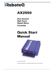
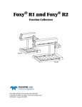
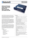
The controller uses a flexible power supply scheme that is best described in Figure 1. In
this diagram, it can be seen that the power for the Controller’s internal microcomputer is
separate from this of the motor drivers. The microcomputer circuit is connected to a DC/
DC converter which takes power from either the Power Control input or the VMot input.
A diode circuit that is included in most controller models, is designed to automatically
select one power source over the other and lets through the source that has the highest
voltage.
Mot1(-)
Mot1(+)
0Vmin
Vmot
Channel 1 MOSFET Power Stage
DC/DC
Channel 2 MOSFET Power Stage
7V min
Vpwr max
GND
Power
Control
&Backup
ENABLE
Microcomputer &
MOSFET Drivers
Vmot
*
0Vmin
Vmot max
GND
GND
Vmot
Mot2(+)
Mot2(-)
* not included in high voltage models
FIGURE 1. Representation of the controller’s Internal Power Circuits
When powered via the Power Control input only, the controller will turn On, but motors will
not be able to turn until power is also present on the VMot wires or Tab.
The Power Control input also serves as the Enable signal for the DC/DC converter. When
floating or pulled to above 1V, the DC/DC converter is active and supplies the controller’s
microcomputer and drivers, thus turning it On. When the Power Control input is pulled to
Ground, the DC/DC converter is stopped and the controller is turned Off.
The Power Control input MUST be connected to Ground to turn the Controller Off. For turning the controller On, even though the Power Control may be left floating, whenever possible pull it to a 12V or higher voltage to keep the controller logic solidly On. You may use a
separate battery to keep the controller alive as the main Motor battery discharges.
The diode that is used to bring power from the main battery is excluded in some high voltage controller models. For these controllers, a separate voltage source must be provided
externally to the Power Control input.
22
Advanced Digital Motor Controllers User Manual
Version 1.3. September 1, 2013
Controller Power
The table below shows the state of the controller depending on the voltage applied to
Power Control and VMot.
TABLE 1. Controller Status depending on Power Control and VMot
Power Control input is
connected to
And Main Battery
Voltage is
Ground
Any Voltage
Controller is Off. Required Off
Configuration.
Floating
0V
Controller is Off. Not Recommended Off Configuration.
Floating (1)
Between 7 and VMotMax
(See VMotMax value in
datasheet)
Controller is On.
7V to max Volts
Below undervoltage threshold
Controller is On.
7V to max Volts
Between undervoltage and
overvoltage limits
Action
Power Stage is Active
Power Stage is Off
Controller is On.
Power Stage is Active
Note1: High voltage controllers are off if Power Control is not connected to a power source.
Note: All 3 ground (-) are connected to each other inside the controller. The two VMot main
battery wires are also connected to each other internally. However, you must never
assume that connecting one wire of a given battery potential will eliminate the need to
connect the other.
Advanced Digital Motor Controllers User Manual
23
Connecting Power and Motors to the Controller
Controller Powering Schemes
Roboteq controllers operate in an environment where high currents may circulate in unexpected manners under certain condition. Please follow these instructions. Roboteq
reserves the right to void product warranty if analysis determines that damage is due to
improper controller power connection.
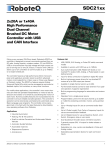
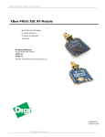
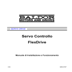
The example diagram on Figure 2 shows how to wire the controller and how to turn power
On and Off. All Roboteq models use a similar power circuit. See the controller datasheet
for the exact wiring diagram for your controller model.
F2
1A
SW1 Main
On/Off Switch 1A
PwrCtrl/Yellow
Note 1
White/M1+
Ground/Black
Motor 1
Backup
Battery
Green/M1Diode
>20A
Resistor
1K, 0.5W
Note 3
White/M2+
Note 2
VMot/Red
VMot/Red
F1
SW2
Emergency
Contactor or
Cut-off Switch
Note 4
+
Motor 2
Green/M2-
Ground/Black
Ground/Black
-
Earth Tab
Note 5
I/O Connector
Main
Battery
Note 6
Do not Connect!
FIGURE 2. Brushed DC controller powering diagram
Mandatory Connections
It is imperative that the controller is connected as shown in the wiring diagram provided in
the datasheet in order to ensure a safe and trouble-free operation. All connections shown
as thick black lines are mandatory.
24
•
Connect the thick black wire(s) or the ground terminal to the minus (-) terminal of
the battery that will be used to power the motors. Connect the thick red wire(s) or
VMot terminal to the plus (+) terminal of the battery. The motor battery may be of
12V up to the maximum voltage specified in the controller model datasheet.
•
The controller must be powered On/Off using switch SW1on the Power Control
wire/terminal. Grounding this line powers Off the controller. Floating or pulling this
line to a voltage will power On the controller. (SW1 is a common SPDT 1 Amp or
more switch).
•
Use a suitable high-current fuse F1 as a safety measure to prevent damage to the
wiring in case of major controller malfunction. (Littlefuse ATO or MAXI series).
Advanced Digital Motor Controllers User Manual
Version 1.3. September 1, 2013
Controller Powering Schemes
•
The battery must be connected in permanence to the controller’s Red wire(s) or
VMot terminal via a high-power emergency switch SW2 as additional safety measure. Partially discharged batteries may not blow the fuse, while still having enough
power left to cause a fire. Leave the switch SW2 closed at all times and open only in
case of an emergency. Use the main On/Off switch SW1 for normal operation. This
will prolong the life of SW2, which is subject to arcing when opening under high
current with consequent danger of contact welding.
•
If installing in an electric vehicle equipped with a Key Switch where SW2 is a contactor, and the key switch energizes the SW2 coil, then implement SW1 as a relay.
Connect the Key Switch to both coils of SW1 and SW2 so cutting off the power to
the vehicle by the key switch and SW2 will set the main switch SW1 in the OFF
position as well.
Connection for Safe Operation with Discharged Batteries (note 1)
The controller will stop functioning when the main battery voltage drops below 7V. To
ensure motor operation with weak or discharged batteries, connect a second battery to the
Power Control wire/terminal via the SW1 switch. This battery will only power the controller’s internal logic. The motors will continue to be powered by the main battery while the
main battery voltage is higher than the secondary battery voltage. This option is valid on all
controller models except the SDCxxxx.
Use precharge Resistor to prevent switch arcing (note 2)
Insert a 1K, 0.5W resistor across the SW2 Emergency Switch. This will cause the controller’s internal capacitors to slowly charge and maintain the full battery voltage by the time
the SW2 switch is turned on and thus eliminate damaging arcing to take place inside the
switch. Make sure that the controller is turned Off with the Power Control wire grounded
while the SW2 switch is off. The controller’s capacitors will not charge if the Power Control
wire is left floating and arcing will then occur when the Emergency switch is turned on.
Protection against Damage due to Regeneration (notes 3 and 4)
Voltage generated by motors rotating while not powered by the controller can cause serious damage even if the controller is Off or disconnected. This protection is highly recommended in any application where high motion inertia exists or when motors can be made
to rotate by towing or pushing (vehicle parking).
•
Use the main SW1 switch on the Power Control wire/terminal to turn Off and keep
Off the controller.
•
Insert a high-current diode (Digikey P/N 10A01CT-ND) to ensure a return path to the
battery in case the fuse is blown. Smaller diodes are acceptable as long as their single pulse current rating is > 20 Amp.
•
Optionally use a Single Pole, Dual Throw switch for SW2 to ground the controller
power input when OFF. If a SPDT switch cannot be used, then consider extending
the diode across the fuse and the switch SW2.
Connect Case to Earth if connecting AC equipment (note 5)
If building a system which uses rechargeable batteries, it must be assumed that periodically a user will connect an AC battery charger to the system. Being connected to the AC
main, the charger may accidentally bring AC high voltage to the system’s chassis and to the
controller's enclosure. Similar danger exists when the controller is powered via a power
supply connected to the mains.
Advanced Digital Motor Controllers User Manual
25
Connecting Power and Motors to the Controller
The controllers are supplied with an Earth tab, which permits earthing the metal case. Connect this tab to a wire connected to the Earth while the charger is plugged in the AC main,
or if the controller is powered by an AC power supply or is being repaired using any other
AC equipment (PC, Voltmeter etc.)
Avoid Ground loops when connecting I/O devices (note 6)
When connecting a PC, encoder, switch or actuators on the I/O connector, be very careful
that you do not create a path from the ground pins on the I/O connector and the battery
minus terminal. Should the controller’s main Ground wires (thick black) be disconnected
while the VMot wires (thick red) are connected, high current would flow from the ground
pins, potentially causing serious damage to the controller and/or your external devices.
•
Do not connect a wire between the I/O connector ground pins and the battery
minus terminal. Look for hidden connection and eliminate them.
•
Have a very firm and secure connection of the controller ground wire and the battery minus terminal.
•
Do not use connectors or switches on the power ground cables.
Important Warning
Do not rely on cutting power to the controller for it to turn Off if the Power Control is
left floating. If motors are spinning because the robot is pushed or because of inertia,
they will act as generators and will turn the controller On, possibly in an unsafe
state. ALWAYS ground the Power Control wire terminal to turn the controller Off and
keep it Off.
Important Warning
Unless you can ensure a steady voltage that is higher than 7V in all conditions, it is
recommended that the battery used to power the controller’s electronics be separate
from the one used to power the motors. This is because it is very likely that the
motor batteries will be subject to very large current loads which may cause the voltage to eventually dip below 7V as the batteries’ charge drops. The separate backup
power supply should be connected to the Power Control input. This warning applies
to all controllers except the SDCxxxx models.
Connecting the Motors
Refer to the datasheet for information on how to wire the motor(s) to a particular motor
controller model.
After connecting the motors, apply a minimal amount of power using the Roborun PC utility with the controller configured in Open Loop speed mode. Verify that the motor spins
in the desired direction. Immediately stop and swap the motor wires if not.
In Closed Loop Speed or Position mode, beware that the motor polarity must match this of
the feedback. If it does not, the motors will runaway with no possibility to stop other than
switching Off the power. The polarity of the Motor or of the feedback device may need to
be changed.
26
Advanced Digital Motor Controllers User Manual
Version 1.3. September 1, 2013
Single Channel Operation
Important Warning
Make sure that your motors have their wires isolated from the motor casing. Some
motors, particularly automotive parts, use only one wire, with the other connected
to the motor’s frame.
If you are using this type of motor, make sure that it is mounted on isolators and that
its casing will not cause a short circuit with other motors and circuits which may
also be inadvertently connected to the same metal chassis.
Single Channel Operation
Dual channel Brushed DC controllers may be ordered with the -S (Single Channel) suffix.
The two channel outputs must be paralleled as shown in the datasheet so that they can
drive a single load with twice the power. To perform in this manner, the controller’s Power
Transistors that are switching in each channel must be perfectly synchronized. Without this
synchronization, the current will flow from one channel to the other and cause the destruction of the controller.
The single channel version of the controller incorporates a hardware setting inside the controller which ensures that both channels switch in a synchronized manner and respond to
commands sent to channel 1.
Important Warning
Before pairing the outputs, attach the motor to one channel and then the other. Verify that the motor responds the same way to command changes.
Power Fuses
For low Amperage applications (below 30A per motor), it is recommended that a fuse be
inserted in series with the main battery circuit as shown above and in the Figure 2 on
page 24.
The fuse will be shared by the two output stages and therefore must be placed before the
Y connection to the two power wires. Fuse rating should be the sum of the expected current on both channels. Note that automotive fuses above 40A are generally slow, will be of
limited effectiveness in protecting the controller and may be omitted in high current application. The fuse will mostly protect the wiring and battery against after the controller has
failed.
Important Warning
Fuses are typically slow to blow and will thus allow temporary excess current to flow
through them for a time (the higher the excess current, the faster the fuse will blow).
This characteristic is desirable in most cases, as it will allow motors to draw surges
during acceleration and braking. However, it also means that the fuse may not be
able to protect the controller.
Advanced Digital Motor Controllers User Manual
27
Connecting Power and Motors to the Controller
Wire Length Limits
The controller regulates the output power by switching the power to the motors On and
Off at high frequencies. At such frequencies, the wires’ inductance produces undesirable
effects such as parasitic RF emissions, ringing and overvoltage peaks. The controller has
built-in capacitors and voltage limiters that will reduce these effects. However, should the
wire inductance be increased, for example by extended wire length, these effects will be
amplified beyond the controller’s capability to correct them. This is particularly the case for
the main battery power wires.
Important Warning
Avoid long connection between the controller and power source, as the added
inductance may cause damage to the controller when operating at high currents. Try
extending the motor wires instead since the added inductance is not harmful on this
side of the controller.
If the controller must be located at a long distance from the power source, the effects of
the wire inductance may be reduced by using one or more of the following techniques:
•
•
Twisting the power and ground wires over the full length of the wires
•
Add a capacitor (10,000uF or higher) near the controller
Use the vehicle’s metallic chassis for ground and run the positive wire along the surface
Electrical Noise Reduction Techniques
As discussed in the above section, the controller uses fast switching technology to control
the amount of power applied to the motors. While the controller incorporates several circuits to keep electrical noise to a minimum, additional techniques can be used to keep the
noise low when installing the controller in an application. Below is a list of techniques you
can try to keep noise emission low:
•
•
•
•
Keep wires as short as possible
Loop wires through ferrite cores
Add snubber RC circuit at motor terminals
Keep controller, wires and battery enclosed in metallic body
Battery Current vs. Motor Current
The controller measures and limits the current that flows through the motors and not the
battery current. Current that flows through the motor is typically higher than the battery
current. This counter-intuitive phenomenon is due to the “flyback” current in the motor’s
inductance. In some cases, the motor current can be extremely high, causing heat and
potentially damage while battery current appears low or reasonable.
The motor’s power is controlled by varying the On/Off duty cycle of the battery voltage
16,000 times per second to the motor from 0% (motor off) to 100 (motor on). Because of
the inductive flyback effect, during the Off time current continues to flow at nearly the
same peak - and not the average - level as during the On time. At low PWM ratios, the
28
Advanced Digital Motor Controllers User Manual
Version 1.3. September 1, 2013
Battery Current vs. Motor Current
peak current - and therefore motor current - can be very high as shown in Figure 4,
“Instant and average current waveforms,” on page 29.
The relation between Battery Current and Motor current is given in the formula below:
Motor Current = Battery Current / PWM ratio
Example: If the controller reports 10A of battery current while at 10% PWM, the current in
the motor is 10 / 0.1 = 100A.
VMot
Off
Motor
On
FIGURE 3. Current flow during operation
On
Off
I mot
Avg
I bat
Avg
FIGURE 4. Instant and average current waveforms
The relation between Battery Current and Motor current is given in the formula below:
Motor Current = Battery Current / PWM Ratio
Example: If the controller reports 10A of battery current while at 10% PWM, the current in
the motor is 10 / 0.1 = 100A.
Important Warning
Do not connect a motor that is rated at a higher current than the controller.
Advanced Digital Motor Controllers User Manual
29
Connecting Power and Motors to the Controller
Power Regeneration Considerations
When a motor is spinning faster than it would normally at the applied voltage, such as
when moving downhill or decelerating, the motor acts like a generator. In such cases, the
current will flow in the opposite direction, back to the power source.
It is therefore essential that the controller be connected to rechargeable batteries. If a
power supply is used instead, the current will attempt to flow back in the power supply
during regeneration, potentially damaging it and/or the controller.
Regeneration can also cause potential problems if the battery is disconnected while the
motors are still spinning. In such a case, the energy generated by the motor will keep the
controller On, and depending on the command level applied at that time, the regenerated
current will attempt to flow back to the battery. Since none is present, the voltage will rise
to potentially unsafe levels. The controller includes an overvoltage protection circuit to prevent damage to the output transistors (see “Using the Controller with a Power Supply” on
page 30). However, if there is a possibility that the motor could be made to spin and generate a voltage higher than 40V, a path to the battery must be provided, even after a fuse is
blown. This can be accomplished by inserting a diode across the fuse as shown in Figure 2
on page 24.
Please download the Application Note “Understanding Regeneration” from the www.roboteq.com for an in-depth discussion of this complex but important topic.
Important Warning
Use the controller only with a rechargeable battery as supply to the Motor Power
wires (thick black and red wires). If a transformer or power supply is used, damage to
the controller and/or power supply may occur during regeneration. See “Using the
Controller with a Power Supply” on page 30 for details.
Important Warning
Avoid switching Off or cutting open the main power cables while the motors are
spinning. Damage to the controller may occur. Always ground the Power Control
wire to turn the controller Off.
Using the Controller with a Power Supply
Using a transformer or a switching power supply is possible but requires special care, as
the current will want to flow back from the motors to the power supply during regeneration. As discussed in “Power Regeneration Considerations” on page 30, if the supply is not
able to absorb and dissipate regenerated current, the voltage will increase until the overvoltage protection circuit cuts off the motors. While this process should not be harmful to
the controller, it may be to the power supply, unless one or more of the protective steps
below is taken:
•
30
Use a power supply that will not suffer damage in case a voltage is applied at its
output that is higher than its own output voltage. This information is seldom published in commercial power supplies, so it is not always possible to obtain positive
reassurance that the supply will survive such a condition.
Advanced Digital Motor Controllers User Manual
Version 1.3. September 1, 2013
Using the Controller with a Power Supply
•
Avoid deceleration that is quicker than the natural deceleration due to the friction in
the motor assembly (motor, gears, load). Any deceleration that would be quicker
than natural friction means that braking energy will need to be taken out of the system, causing a reverse current flow and voltage rise. See “Important Warning” on
page 77.
•
Place a battery in parallel with the power supply output. This will provide a reservoir
into which regeneration current can flow. It will also be very helpful for delivering
high current surges during motor acceleration, making it possible to use a lower
current power supply. Batteries mounted in this way should be connected for the
first time only while fully charged and should not be allowed to discharge. The
power supply will be required to output unsafe amounts of current if connected
directly to a discharged battery. Consider using a decoupling diode on the power
supply’s output to prevent battery or regeneration current to flow back into the
power supply.
•
Place a resistive load in parallel with the power supply, with a circuit to enable that
load during regeneration. This solution is more complex but will provide a safe path
for the braking energy into a load designed to dissipate it. To prevent current from
flowing from the power supply into the load during normal operation, an active
switch would enable the load when the voltage rises above the nominal output of
the power supply. The controller can be configured to activate the load using a digital output configured to turn on when overvoltage condition is detected.
Advanced Digital Motor Controllers User Manual
31
Connecting Power and Motors to the Controller
32
Advanced Digital Motor Controllers User Manual
Version 1.3. September 1, 2013
Possible Failure Causes
Safety
Recommendations
SECTION 2
In many applications, Roboteq controllers drive high power motors that move parts and
equipment at high speed and/or with very high force. In case of malfunction, potentially
enormous forces can be applied at the wrong time and/or wrong place causing serious
damage to property and/or harm to person. While Roboteq controllers operate very reliably, and failures are rare, a failure is possible as with any other electronic equipment. If
there is any danger that a loss of motor control can cause damage or injury, you must plan
on that possibility and implement methods for stopping the motor independently of the
controller operation.
Below is a list of failure categories, their effect and possible ways to regain control, or minimize the consequences. The list of possible failures is not exhaustive and the suggested
prevention methods are provided as examples for information only.
Important Safety Disclaimer
Dangerous uncontrolled motor runaway condition can occur for a number of reasons, including, but not limited to: command or feedback wiring failure, configuration error, faulty firmware, errors in user MicroBasic script or in user program, or
controller hardware failure. The user must assume that such failures can occur and
must take all measures necessary to make his/her system safe in all conditions.
The information contained in this manual, and in this section in particular, is provided for information only. Roboteq will not be liable in case of damage or injury as a
result of product misuse or failure.
Possible Failure Causes
Dangerous unintended motor operation could occur for a number of reasons, including, but
not limited to:
•
•
•
Failure in Command device
Feedback sensors malfunction
Wiring errors or failure
Advanced Digital Motor Controllers User Manual
33
Safety Recommendations
•
•
•
•
Controller configuration error
Faulty firmware
Errors or oversights in user MicroBasic scripts
Controller hardware failure
Motor Deactivation in Normal Operation
In normal operation, the controller is always able to turn off the motor if it detects faults or
if instructed to do so from an external command.
In case of wiring problem, sensor malfunction, firmware failure or error in user Microbasic
scripts, the controller may be in a situation where the motors are turned on and kept on as
long as the controller is powered. A number of features discussed throughout this manual
are available to stop motor operation in case of abnormal situation. These include:
•
•
•
•
•
•
•
Watchdog on missing incoming serial/USB commands
Loss detection of Radio Pulse
Analog command outside valid range
Limit switches
Stall detection
Close Loop error detection
Other …
Additional features can easily be added using MicroBasic scripting.
Ultimately, the controller can be simply turned off by grounding the Power Control pin.
Assuming there is no hardware damage in the power stage, the controller output will be
off (i.e. motor wires floating) when the controller is off.
Important Warning:
While cutting the power to the motors is generally the best thing to do in case of
major failure, it may not necessarily result in a safe situation.
Motor Deactivation in Case of Output Stage Hardware Failure
On brushed DC motor controllers, the power stage for each motor is composed of 4 MOSFETs (semiconductor switches). In some case of failures to MOSFETs in the power stage,
it is possible that one or both motors will remain permanently powered with no way to
stop them either via software or by turning the controller off.
On brushless motor controllers, shorted MOSFETs will not cause the motor to turn on its
own. Nevertheless, it is still advised to follow the recommendations included in this section.
34
Advanced Digital Motor Controllers User Manual
Version 1.3. September 1, 2013
Motor Deactivation in Case of Output Stage Hardware Failure
The figures below show all the possible combinations of shorted MOSFETs switches.
+
+
+
+
+
2
5
+
1
4
7
-
-
-
3
6
-
FIGURE 5. MOSFET Failures resulting in no motor activation
+
+
+
+
8
+
10
+
12
+
14
-
9
11
-
-
13
-
FIGURE 6. MOSFET Failures resulting in battery short circuit and no motor activation
+
+
15
-
16
-
FIGURE 7. MOSFET Failures resulting in motor activation
Advanced Digital Motor Controllers User Manual
35
Safety Recommendations
Two failure conditions (15 and 16) will result in the motor spinning out of control regardless
whether the controller is on or off. While these failure conditions are rare, users must take
them into account and provide means to cut all power to the controller's power stage.
Manual Emergency Power Disconnect
In systems where the operator is within physical reach of the controller, the simplest
safety device is the emergency disconnect switch that is shown in the wiring diagram
inside all controller datasheets, and in the example diagram below.
SW1 Main
On/Off Switch
PwrCtrl/Yellow
White/M1+
Ground/Black
Motor 1
Backup
Battery
Green/M1-
White/M2+
VMot/Red
VMot/Red
Motor 2
SW2
Emergency
Contactor or
Cut-off Switch
+
-
Green/M2-
Ground/Black
Ground/Black
Earth Tab
I/O Connector
Main
Battery
FIGURE 8. Example powering diagram (Brushed DC motor controller)
The switch must be placed visibly and be easy to operate. Prefer “mushroom” emergency
stop push buttons. Make sure that the switches are rated at the maximum current that can
be expected to flow through all motors at the same time.
FIGURE 9. "Mushroom" type Emergency Disconnect Switch
36
Advanced Digital Motor Controllers User Manual
Version 1.3. September 1, 2013
Remote Emergency Power Disconnect
Remote Emergency Power Disconnect
In remote controlled systems, the emergency switch must be replaced by a high power
contactor relay as shown in Figure 10. The relay must be normally open and be activated
using an RC switch on a separate radio channel. The receiver should preferably be powered
directly from the system's battery. If powered from the controller's 5V output, keep in
mind that in case of a total failure of the controller, the 5V output may or may not be interrupted.
Controller
On/Off Switch
PwrCtrl
Ground
VMot
RC Receiver
RC Switch
RC3
RC2
I/O Connector
RC1
+
-
Ground
Main
Battery
FIGURE 10. Example of remotely operated safety disconnect
The receiver must operate in such a way that the contactor relay will be off if the transmitter if off or out of range.
The transmitter should have a visible and easy to reach emergency switch for the operator.
That switch will be used to deactivate the relay remotely. It could also be used to shutdown entirely the transmitter, assuming it is determined for certain that this will deactivate
the relay at the controller.
Protection using Supervisory Microcomputer
In applications where the controller is commanded by a PC, a microcomputer or a PLC,
that supervisory system could be used to verify that the controller is still responding and
cut the power to the controller's power stage in case a malfunction is detected. The supervisory system would only require a digital output or other means to activate/deactivate the
contactor relay as shown in the figure below.
Advanced Digital Motor Controllers User Manual
37
Safety Recommendations
Controller
On/Off Switch
PwrCtrl
Ground
PC, PLC or
Microcomputer
VMot
Digital Output
I/O Connector
RS232
+
Ground
Main
Battery
FIGURE 11. Example of safety disconnect via supervisory system
Self Protection against Power Stage Failure
If the controller processor is still operational, it can self detect several, although not all, situations where a motor is running while the power stage is off. The figure below shows a
protection circuit using an external contactor relay.
Controller
On/Off Switch
PwrCtrl
Ground
VMot
Contactor
Digital Out
to +40V Max
+
Emergency
Disconnect
-
I/O Connector
Ground
Main
Battery
FIGURE 12. Self-protection circuit using contactor
38
Advanced Digital Motor Controllers User Manual
Version 1.3. September 1, 2013
Self Protection against Power Stage Failure
The controller must have the Power Control input wired to the battery so that it can operate and communicate independently of the power stage. The controller’s processor will
then activate the contactor coil through a digital output configured to turn on when the “No
MOSFET Failure” condition is true. The controller will automatically deactivate the coil if
the output is expected to be off and battery current is above 500mA to 2.5A (depending on
the controller model) for more than 0.5s.
The contactor must be rated high enough so that it can cut the full load current. For even
higher safety, additional precaution should be taken to prevent and to detect fused contactor blades.
This contactor circuit will only detect and protect against damaged output stage conditions. It will not protect against all other types of fault. Notice therefore, the presence of an
emergency switch in series with the contactor coil. This switch should be operated manually or remotely, as discussed in the “Manual Emergency Power Disconnect” on page 36,
the “Remote Emergency Power Disconnect” on page 37 and the “Protection using Supervisory Microcomputer” on page 37.
Using this contactor circuit, turning off the controller will normally deactivate the digital output and this will cut the power to the controller's output stage.
Important Warning
Fully autonomous and unsupervised systems cannot depend on electronics alone to
ensure absolute safety. While a number of techniques can be used to improve safety,
they will minimize but never totally eliminate risks. Such systems must be mechanically designed so that no moving parts can ever cause harm in any circumstances.
Advanced Digital Motor Controllers User Manual
39
Safety Recommendations
40
Advanced Digital Motor Controllers User Manual
Version 1.3. September 1, 2013
Controller Connections
SECTION 3
Connecting
Sensors and
Actuators to
Input/Outputs
This section describes the various inputs and outputs and provides guidance on how to
connect sensors, actuators or other accessories to them.
Controller Connections
The controller uses a set of power connections (located on the back of the unit) and, on the
front, and DSub connectors for all necessary connections.
The power connections are used for connection to the batteries and motor, and will typically carry large current loads. Details on the controller’s power wiring can be found at
“Connecting Power and Motors to the Controller” on page 21.
The DSub connectors are used for all low-voltage, low-current connections to the Radio,
Microcontroller, sensors and accessories. This section covers only the connections to sensors and actuators.
For information on how to connect the RS232 port, see “Serial (RS232/USB) Operation” on
page 111.
The remainder of this section describes how to connect sensors and actuators to the controller’s low-voltage I/O pins that are located on the DSub connectors.
Advanced Digital Motor Controllers User Manual
41
Connecting Sensors and Actuators to Input/Outputs
Controller’s Inputs and Outputs
The controller includes several inputs and outputs for various sensors and actuators.
Depending on the selected operating mode, some of these I/Os provide command, feedback and/or safety information to the controller.
When the controller operates in modes that do not use these I/Os, these signals are
ignored or can become available via the USB/RS232 port for user application. Below is a
summary of the available signals and the modes in which they are used by the controller.
The actual number of signal of each type, voltage or current specification, and their position
on the I/O connector is given in the controller datasheet.
TABLE 2. Controller’s IO signals and definitions
Signal
I/O type
DOUT1
to
DOUTn
Digital Output
Use/Activation
- Activated when motor(s) is powered
- Activated when motor(s) is reversed
- Activated when overvoltage
- Miror Status LED
- Deactivates when output stage fault
- User activated (RS232/USB)
Digital Input
DIN1
to
DINn
- Safety Stop
- Emergency stop
- Motor Stop (deadman switch)
- Invert motor direction
- Forward or reverse limit switch
- Run MicroBasic Script
- Load Home counter
42
AIN1
to
AINn
Analog Input
PIN1
to
PINn
Pulse Input
ENC1a/b
to
ENC2a/b
Encoder Inputs
- Command for motor(s)
- Speed or position feedback
- Trigger Action similar to Digital Input if under or over userselectable threshold
- Command for motor(s)
- Speed or position feedback
- Trigger Action similar to Digital Input if under or over user
selectable threshold
- Command for motor(s)
- Speed or position feedback
- Trigger action similar to Digital Input if under or over userselectable count threshold
Advanced Digital Motor Controllers User Manual
Version 1.3. September 1, 2013
Connecting devices to Digital Outputs
Connecting devices to Digital Outputs
Depending on the controller model, 2 to 8 Digital Ouputs are available for multiple purposes. The Outputs are Open Drain MOSFET outputs capable of driving over 1A at up to
24V. See datasheet for detailed specifications.
Since the outputs are Open Drain, the output will be pulled to ground when activated.
The load must therefore be connected to the output at one end and to a positive voltage
source (e.g. a 24V battery) at the other.
Connecting Resistive Loads to Outputs
Resistive or other non-inductive loads can be connected simply as shown in the diagram
below.
Lights, LEDs, or any other
non-inductive load
+
Up to
24V
DC
-
DOUT
Internal
Transistor
Ground
FIGURE 13. Connecting resistive loads to DOUT pins
Connecting Inductive loads to Outputs
The diagrams on Figure 14 show how to connect a relay, solenoid, valve, small motor, or
other inductive load to a Digital Output:
Relay, Valve
Motor, Solenoid
or other Inductive Load
+
Up to
24V
DC
-
DOUT
Internal
Transistor
Ground
FIGURE 14. Connecting inductive loads to DOUT pins
Advanced Digital Motor Controllers User Manual
43
Connecting Sensors and Actuators to Input/Outputs
Important Warning
Overvoltage spikes induced by switching inductive loads, such as solenoids or
relays, will destroy the transistor unless a protection diode is used.
Connecting Switches or Devices to Inputs shared with Outputs
On HDCxxxx and HBLxxxx controllers, Digital inputs DIN12 to DIN19 share the connector
pins with digital outputs DOUT1 to DOUT8. When the digital outputs are in the Off state,
these outputs can be used as inputs to read the presence or absence of a voltage at these
pins.
+5V Out
1K
to
10K
50K
DIN12 to DIN19
(DOUT1 to DOUT7)
Input
Buffer
Output
Driver
GND
FIGURE 15. Switch wiring to Inputs shared with Outputs
For better noise immunity, an external pull up resistor should be installed even though one
is already present inside the controller.
Connecting Switches or Devices to direct Digital Inputs
The controller Digital Inputs are high impedance lines with a pull down resistor built into
the controller. Therefore it will report an On state if unconnected, and a simple switch as
shown on Figure 16 is necessary to activate it. When a pull up switch is used, for better
noise immunity, an external pull down resistor should be installed even though one is
already present inside the controller.
5V Out
DIN
20kOhm
1K
to
10K
33kOhm
Ground
FIGURE 16. Pull up switch wirings to DIN pins
44
Advanced Digital Motor Controllers User Manual
Version 1.3. September 1, 2013
Connecting a Voltage Source to Analog Inputs
A pull up resistor must be installed when using a pull down switch.
5V Out
1K to
10K
Ohm
20kOhm
33kOhm
DIN
Ground
FIGURE 17. Pull down switch wirings to DIN pins
Important Warning
Do not activate an output when it is used as input. If the input is connected directly
to a positive voltage when the output is activated, a short circuit will occur. Always
pull the input up via a resistor.
Connecting a Voltage Source to Analog Inputs
Connecting sensors with variable voltage output to the controller is simply done by making
a direct connection to the controller’s analog inputs. When measuring absolute voltages,
configure the input in “Absolute Mode” using the PC Utility. See also “ACTR - Set Analog
Input Center (0) Level” on page 201.
+5V
Internal Resistors
and Converter
AIN
20kOhm
A/D
V
0-5V
Source
33kOhm
Ground
FIGURE 18. Voltage source connected to Analog inputs
Advanced Digital Motor Controllers User Manual
45
Connecting Sensors and Actuators to Input/Outputs
Connecting Potentiometers to Analog Inputs
Potentiometers mounted on a foot pedal or inside a joystick are an effective method for giving command to the controller. In closed loop mode, a potentiometer is typically used to
provide position feedback information to the controller.
Connecting the potentiometer to the controller is as simple as shown in the diagram on
Figure 19.
The potentiometer value is limited at the low end by the current that will flow through it
and which should ideally not exceed 5 or 10mA. If the potentiometer value is too high, the
analog voltage at the pot’s middle point will be distorted by the input’s resistance to ground
of 53K. A high value potentiometer also makes the input sensitive to noise, particularly if
wiring is long. Potentiometers of 1K or 5K are recommended values.
+5V
Internal Resistors
and Converter
20kOhm
A/D
1K to 10K
Ohm Pot
33kOhm
Ground
FIGURE 19. Potentiometer wiring in Position mode
Because the voltage at the potentiometer output is related to the actual voltage at the controller’s 5V output, configure the analog input in “Relative Mode”. This mode measures the
actual voltage at the 5V output in order to eliminate any imprecision due to source voltage
variations. Configure using the PC Utility or see “ACTR - Set Analog Input Center (0) Level”
on page 201.
Connecting Potentiometers for Commands with Safety band guards
When a potentiometer is used for sensing a critical command (Speed or Brake, for example) it is critically important that the controller reverts to a safe condition in case wiring is
sectioned. This can be done by adding resistors at each end of the potentiometer so that
the full 0V or the full 5V will never be present, during normal operation, when the potentiometer is moved end to end.
Using this circuit shown below, the Analog input will be pulled to 0V if the two top wires of
the pot are cut, and pulled to 5V if the bottom wire is cut. In normal operation, using the
shown resistor values, the analog voltage at the input will vary from 0.2V to 4.8V.
46
Advanced Digital Motor Controllers User Manual
Version 1.3. September 1, 2013
Connecting Tachometer to Analog Inputs
220 Ohm
+5V
Internal Resistors
and Converter
20kOhm
5K Ohm Pot
A/D
33kOhm
220 Ohm
Ground
FIGURE 20. Potentiometer wiring in Position mode
The controller’s analog channels are configured by default so that the min and max command range is from 0.25V to 4.75V. These values can be changed using the PC configuration utility. This ensures that the full travel of the pot is used to generate a command that
spans from full min to full max.
If the Min/Max safety is enabled for the selected analog input, the command will be considered invalid if the voltage is lower than 0.1V or higher than 4.9. These values cannot be
changed.
Connecting Tachometer to Analog Inputs
When operating in closed loop speed mode, tachometers can be connected to the controller to report the measured motor speed. The tachometer can be a good quality brushed DC
motor used as a generator. The tachometer shaft must be directly tied to that of the motor
with the least possible slack.
Since the controller only accepts a 0 to 5V positive voltage as its input, the circuit shown in
Figure 21 must be used between the controller and the tachometer: a 10kOhm potentiometer is used to scale the tachometer output voltage to -2.5V (max reverse speed) and
+2.5V (max forward speed). The two 1kOhm resistors form a voltage divider that sets the
idle voltage at mid-point (2.5V), which is interpreted as the zero position by the controller.
With this circuitry, the controller will see 2.5V at its input when the tachometer is stopped,
0V when running in full reverse, and +5V in full forward.
Advanced Digital Motor Controllers User Manual
47
Connecting Sensors and Actuators to Input/Outputs
+5V
1kOhm
Internal Resistors
and Converter
Max Speed Adjust
10kOhm pot
20KOhm
AIN
Tach
A/D
33KOhm
1kOhm
Ground
FIGURE 21. Tachometer wiring diagram
The tachometers can generate voltages in excess of 2.5 volts at full speed. It is important,
therefore, to set the potentiometer to the minimum value (cursor all the way down per this
drawing) during the first installation.
Since in closed loop control the measured speed is the basis for the controller’s power output (i.e. deliver more power if slower than desired speed, less if higher), an adjustment and
calibration phase is necessary. This procedure is described in “Closed Loop Speed Mode”
on page 87.
Important Warning
The tachometer’s polarity must be such that a positive voltage is generated to the
controller’s input when the motor is rotating in the forward direction. If the polarity
is inverted, this will cause the motor to run away to the maximum speed as soon as
the controller is powered and eventually trigger the closed loop error and stop. If this
protection is disabled, there will be no way of stopping it other than pressing the
emergency stop button or disconnecting the power.
Connecting External Thermistor to Analog Inputs
Using external thermistors, the controller can be made to supervise the motor’s temperature and cut the power output in case of overheating. Connecting thermistors is done
according to the diagram shown in Figure 22. Use a 10kOhm Negative Coefficient Thermistor (NTC) with the temperature/resistance characteristics shown in the table below. Recommended part is Vishay NTCLE100E3103JB0, Digikey item BC2301-ND.
TABLE 3. Recommended NTC characteristics
48
Temp (oC)
-25
0
25
50
75
100
Resistance (kOhm)
129
32.5
10.00
3.60
1.48
0.67
Advanced Digital Motor Controllers User Manual
Version 1.3. September 1, 2013
Connecting External Thermistor to Analog Inputs
+5V
Internal Resistors
and Converter
10kOhm
NTC
Thermistor
20kOhm
A/D
10kOhm
33kOhm
Ground
FIGURE 22. NTC Thermistor wiring diagram
Thermistors are non-linear devices. Using the circuit described on Figure 22, the controller
will read the following values according to the temperature. For best precision, the analog
input must be configured to read in Relative Mode.
The analog input must be configured so that the minimum range voltage matches the
desired temperature and that an action be triggered when that limit is reached. For example 500mV for 80oC, according to the table. The action can be any of the actions in the list.
An emergency or safety stop (i.e. stop power until operator moves command to 0) would
be a typical action to trigger.
Volts
4.5
4
3.5
3
2.5
2
1.5
1
0.5
90
10
0
11
0
12
0
13
0
14
0
15
0
70
80
60
50
30
40
20
0
10
0
0
0
-1
-2
-3
-4
0
0
oC
FIGURE 23. Voltage reading by controller vs. NTC temperature
Note: The voltage values in this chart are provided for reference only and may vary based
on the Thermistor model/brand and the resistor precision. It is recommended that you verify and calibrate your circuit if it is to be used for safety protection.
Advanced Digital Motor Controllers User Manual
49
Connecting Sensors and Actuators to Input/Outputs
Using the Analog Inputs to Monitor External Voltages
The analog inputs may also be used to monitor the battery level or any other DC voltage. If
the voltage to measure is up to 5V, the voltage can be brought directly to the input pin. To
measure higher voltage, insert two resistors wired as voltage divider. The figure shows
a 10x divider capable of measuring voltages up to 50V.
Ext Voltage
IN
+5V
Internal Resistors
and Converter
47kOhm
20kOhm
A/D
4.7kOhm
33kOhm
Ground
FIGURE 24. Battery voltage monitoring circuit
Connecting Sensors to Pulse Inputs
The controller has several pulse inputs capable of capturing Pulse Length, Duty Cycle or
Frequency with excellent precision. Being a digital signal, pulses are also immune to noise
compared to analog inputs.
Connecting to RC Radios
The pulse inputs are designed to allow direct connection to an RC radio without additional
components.
Optional
Power
to
Radio
5V Out
Controller
Power
R/C Channel 1
R/C Radio
R/C Channel 2
MCU
R/C Radio Ground
Controller
Ground
FIGURE 25. RC Radio powered by controller electrical diagram
50
Advanced Digital Motor Controllers User Manual
Version 1.3. September 1, 2013
Connecting Optical Encoders
Connecting to PWM Joysticks and Position Sensors
The controller’s pulse inputs can also be used to connect to sensors with PWM outputs.
These sensors provide excellent noise immunity and precision. When using PWM sensors,
configure the pulse input in Duty Cycle mode. Beware that the sensor should always be
pulsing and never output a steady DC voltage at its ends. The absence of pulses is considered by the controller as a loss of signal. See also “Using Sensors with PWM Outputs for
Commands” on page 60.
Connecting Optical Encoders
Optical Incremental Encoders Overview
Optical incremental encoders are a means for capturing speed and travelled distance on a
motor. Unlike absolute encoders which give out a multi-bit number (depending on the resolution), incremental encoders output pulses as they rotate. Counting the pulses tells the
application how many revolutions, or fractions of, the motor has turned. Rotation velocity
can be determined from the time interval between pulses or by the number of pulses
within a given time period. Because they are digital devices, incremental encoders will
measure distance and speed with perfect accuracy.
Since motors can move in forward and reverse directions, it is necessary to differentiate
the manner that pulses are counted so that they can increment or decrement a position
counter in the application. Quadrature encoders have dual channels, A and B, which are
electrically phased 90° apart. Thus, direction of rotation can be determined by monitoring
the phase relationship between the two channels. In addition, with a dual-channel encoder,
a four-time multiplication of resolution is achieved by counting the rising and falling edges
of each channel (A and B). For example, an encoder that produces 250 Pulses per Revolution (PPR) can generate 1,000 Counts per Revolution (CPR) after quadrature.
A Channel
1 Pulse
= 4 Transitions
= 4 Counts
B Channel
Quadrature
Signal
Count Up
Count Down
FIGURE 26. Quadrature encoder output waveform
The figure below shows the typical construction of a quadrature encoder. As the disk
rotates in front of the stationary mask, it shutters light from the LED. The light that passes
through the mask is received by the photo detectors. Two photo detectors are placed side
by side at so that the light making it through the mask hits one detector after the other to
produces the 90o phased pulses.
Advanced Digital Motor Controllers User Manual
51
Connecting Sensors and Actuators to Input/Outputs
LED light source
Rotating
encoder disk
Stationary mask
Photodetector
FIGURE 27. Typical quadrature encoder construction
Unlike absolute encoders, incremental encoders have no retention of absolute position
upon power loss. When used in positioning applications, the controller must move the
motor until a limit switch is reached. This position is then used as the zero reference for all
subsequent moves.
Recommended Encoder Types
The module may be used with most incremental encoder module as long as they include
the following features:
•
•
•
Two quadrature outputs (Ch A, Ch B), single ended or differential signals
3.0V minimum swing between 0 Level and 1 Level on quadrature output
5VDC operation. 50mA or less current consumption per encoder
More sophisticated incremental encoders with index, and other features may be used,
however these additional capabilities will be ignored.
The choice of encoder resolution is very wide and is constrained by the module’s maximum pulse count at the high end and measurement resolution for speed at the low end.
Specifically, the controller’s encoder interface can process 1 million counts per second
(30 000 counts per second max on SDCxxxx). As discussed above, a count is generated for
each transition on the Channel A and Channel B. Therefore the module will work with
encoders outputting up to 62,500 pulses per second.
Commercial encoders are rated by their numbers of “Pulses per Revolution” (also sometimes referred as “Number of Lines” or “Cycles per Revolution”). Carefully read the manufacturer’s datasheet to understand whether this number represents the number of pulses
that are output by each channel during the course of a 360o revolution rather than the total
number of transitions on both channels during a 360o revolution. The second number is 4
times larger than the first one.
The formula below gives the pulse frequency at a given RPM and encoder resolution in
Pulses per Revolution.
Pulse Frequency in counts per second = RPM / 60 * PPR * 4
Example: a motor spinning at 10,000 RPM max, with an encoder with 200 Pulses per Revolution would generate:
52
Advanced Digital Motor Controllers User Manual
Version 1.3. September 1, 2013
Connecting the Encoder
10,000 / 60 * 200 * 4 = 133.3 kHz which is well within the 1MHz maximum supported by
the encoder input.
An encoder with a 200 Pulses per Revolutions is a good choice for most applications.
A higher resolution will cause the counter to count faster than necessary and possibly
reach the controller’s maximum frequency limit.
An encoder with a much lower resolution will cause speed to be measured with less precision.
Connecting the Encoder
Encoders connect directly to pins present on the controller’s connector. The connector provides 5V power to the encoders and has inputs for the two quadrature signals from each
encoder. The figure below shows the connection to the encoder.
5V Out
ENC1A (ENC2A)
5V
Ch A
Encoder
GND
Controller
Ch B
ENC1B (ENC2B)
GND
FIGURE 28. Controller connection to typical Encoder
Cable Length and Noise Considerations
Cable should not exceed one 3’ (one meter) to avoid electrical noise to be captured by the
wiring. A ferrite core filter must be inserted near the controller for length beyond 2’ (60
cm). For longer cable length use an oscilloscope to verify signal integrity on each of the
pulse channels and on the power supply.
Advanced Digital Motor Controllers User Manual
53
Connecting Sensors and Actuators to Input/Outputs
Ferrite Core
Encoder
Controller
FIGURE 29. Use ferrite core on cable length beyond 2’ or 60cm
Important Warning
Excessive cable length will cause electrical noise to be captured by the controller and
cause erratic functioning that may lead to failure. In such situation, stop operation
immediately.
Motor - Encoder Polarity Matching
When using encoders for closed loop speed or position control, it is imperative that when
the motor is turning in the forward direction, the counter increments its value and a positive speed value is measured. The counter value can be viewed using the PC utility.
If the Encoder counts backwards when the motor moves forward, correct this by either:
1- Swapping Channel A and Channel B on the encoder connector. This will cause the
encoder module to reverse the count direction, or
2- Swapping the leads on the motor. This will cause the motor to rotate in the opposite
direction.
54
Advanced Digital Motor Controllers User Manual
Version 1.3. September 1, 2013
Input Command Modes and Priorities
Command
Modes
SECTION 4
This section discusses the controller’s normal operation in all its supported operating
modes.
Input Command Modes and Priorities
The controller will accept commands from one of the following sources
•
•
•
•
•
Serial data (RS232, USB, MicroBasic script)
Pulse (R/C radio, PWM, Frequency)
Analog signal (0 to 5V)
Spektrum Radio (on selected models)
CAN Interface
One, many or all command modes can be enabled at the same time. When multiple
modes are enabled, the controller will select which mode to use based on a user selectable priority scheme.
Setting the priorities is done using the PC configuration utility. See “Commands Parameters” on page 233.
This scheme uses a priority table containing three parameters and let you select which
mode must be used in each priority order. During operation, the controller reads the first
priority parameter and switches to that command mode. If that command mode is found
to be active, that command is then used. If no valid command is detected, the controller
switches to the mode defined in the next priority parameter. If no valid command is recognized in that mode, the controller then repeats the operation with the third priority parameter. If no valid command is recognized in that last mode, the controller applies a default
command value that can be set by the user (typically 0).
Advanced Digital Motor Controllers User Manual
55
Command Modes
Pulse
tes
eR
t eS
Serial/USB
Analog
FIGURE 30. Controller’s possible command modes
In the Serial mode, the mode is considered as active if commands (starting with “!”) arrive
within the watchdog timeout period via the RS232 or USB ports. The mode will be considered inactive, and the next lower priority level will be selected as soon as the watchdog
timer expires. Note that disabling the watchdog will cause the serial mode to be always
active after the first command is received, and the controller will never switch to a lower
priority mode.
In the pulse mode, the mode is considered active if a valid pulse train is found and remains
present.
In analog mode, the mode is considered active at all time, unless the Center at Start safety
is enabled. In this case, the Analog mode will activate only after the joystick has been centered. The Keep within Min/Max safety mode will also cause the analog mode to become
inactive, and thus enable the next lower priority mode, if the input is outside of a safe
range.
The example in Figure 30 shows the controller connected to a microcomputer, a RC radio,
and an analog joystick. If the priority registers are set as in the configuration below:
1- Serial
2- Pulse
3- Analog
then the active command at any given time is given in the table below.
TABLE 4. Priority resolution example
56
Microcomputer
Sending commands
Valid Pulses
Received
Analog joystick
within safe Min/Max
Yes
Don’t care
Don’t care
Serial
No
Yes
Don’t care
RC mode
No
No
Yes
Analog mode
No
No
No
User selectable default value
Advanced Digital Motor Controllers User Manual
Command mode
selected
Version 1.3. September 1, 2013
Operating the Controller in RC mode
Note that it is possible to set a priority level to “None”. For example, the priority table
1 - Serial
2 - RC Pulse
3 - None
will only arbitrate and use Serial or RC Pulse commands.
USB vs Serial Communication Arbitration
On controllers equipped with a USB port, commands may arrive through the RS232 or the
USB port at the same time. They are executed as they arrive in a first come first served
manner. Commands that are arriving via USB are replied on USB. Commands arriving via
the UART are replied on the UART. Redirection symbol for redirecting outputs to the other
port exists (e.g. a command can be made to respond on USB even though it arrived on
RS232).
CAN Commands Arbitration
On controllers fitted with a CAN interface, commands received via CAN are processed as
they arrive regardless if any other mode is active at the same time. Care must be taken to
avoid conflicting commands from different sources. Queries of operating parameters will
not interfere with queries from serial or USB.
Commands issued from MicroBasic scripts
When sending a Motor or Digital Output command from a MicroBasic script, it will be
interpreted by the controller the same way as a serial command (RS232 or USB). If a serial
command is received from the serial/USB port at the same time a command is sent from
the script, both will be accepted and this can cause conflicts if they are both relating to the
same channel. Care must be taken to keep to avoid, for example, cases where the script
commands one motor to go to a set level while a serial command is received to set the
motor to a different level.
Important Warning
When running a script that sends motor command, make sure you click “Mute” in
the PC utility. Otherwise, the PC will be sending motor commands continuously and
these will interfere with the script commands.
Script commands are also subject to the serial Watchdog timer and share the same
priority level as Serial commands. Use the “Command Priorities” on page 114 to set
the priority of commands issued from the script vs commands received from the
Pulse Inputs or Analog Inputs.
Operating the Controller in RC mode
The controller can be directly connected to an R/C receiver. In this mode, the speed or
position information is contained in pulses whose width varies proportionally with the joysticks’ positions. The controller mode is compatible with all popular brands of RC transmitters.
Advanced Digital Motor Controllers User Manual
57
Command Modes
The RC mode provides the simplest method for remotely controlling a robotic vehicle: little
else is required other than connecting the controller to the RC receiver and powering it On.
tes
eR
teS
FIGURE 31. R/C radio control mode
The speed or position information is communicated to the controller by the width of a
pulse from the RC receiver: a pulse width of 1.0 millisecond indicates the minimum joystick
position and 2.0 milliseconds indicates the maximum joystick position. When the joystick is
in the center position, the pulse should be 1.5ms.
joystick position:
min
center
max
1.05ms
0.45ms
R/C pulse timing:
0.9ms
FIGURE 32. Joystick position vs. pulse duration default values
The controller has a very accurate pulse capture input and is capable of detecting changes
in joystick position (and therefore pulse width) as small as 0.1%. This resolution is superior
to the one usually found in most low cost RC transmitters. The controller will therefore be
able to take advantage of the better precision and better control available from a higher
quality RC radio, although it will work fine with lesser expensive radios as well.
Input RC Channel Selection
The controllers features 5 or 6 inputs, depending on the model type, that can be used for
pulse capture. Using different configuration parameters, any RC input can be used as command for any motor channels. The controller’s factory default defines two channels for RC
58
Advanced Digital Motor Controllers User Manual
Version 1.3. September 1, 2013
Operating the Controller in RC mode
capture. Which channel and which pin on the input connector depends on the controller
model and can be found in the controller’s datasheet.
Changing the input assignment is done using the PC Configuration utility. See “Pulse
Inputs Configurations and Uses” on page 68.
Input RC Channel Configuration
Internally, the measured pulse width is compared to the reference minimum, center and
maximum pulse width values. From this is generated a command number ranging from 1000 (when the joystick is in the min. position), to 0 (when the joystick is in the center position) to +1000 (when the joystick is in the max position). This number is then used to set
the motor’ desired speed or position that the controller will then attempt to reach.
For best results, reliability and safety, the controller will also perform a series of corrections, adjustments and checks to the R/C commands, as described below.
Automatic Joystick Range Calibration
For best control accuracy, the controller can be calibrated to capture and use your radio’s
specific timing characteristics and store them into its internal Flash memory. This is done
using a simple calibration procedure described on page 66.
Deadband Insertion
The controller allows for a selectable amount of joystick movement to take place around
the center position before activating the motors. See the full description of this feature at
“Deadband Selection” on page 67
Command Exponentiation
The controller can also be set to translate the joystick motor commands so that the motor
respond differently depending on whether the joystick is near the center or near the
extremes. Five different exponential or logarithmic translation curves may be applied.
Since this feature applies to the R/C, Analog and RS232 modes, it is described in detail in
“Exponent Factor Application” on page 68, in the General Operation section of the manual.
Reception Watchdog
Immediately after it is powered on, if in the R/C mode, the controller is ready to receive
pulses from the RC radio.
If valid pulses are received on any of the enabled Pulse input channels, the controller will
consider the RC Pulse mode as active. If no higher priority command is currently active
(See “Input Command Modes and Priorities” on page 55), the captured RC pulses will
serve to activate the motors.
If no valid RC pulses reach the controller for more than 500ms, the controller no longer
considers it is in the RC mode and a lower priority command type will be accepted if present.
Advanced Digital Motor Controllers User Manual
59
Command Modes
Important Warning
Some receivers include their own supervision of the radio signals and will move their servo
outputs to a safe position in case of signal loss. Using these types of receiver, the controller will always be receiving pulses even with the transmitter off.
Using Sensors with PWM Outputs for Commands
The controller’s Pulse inputs can be used with various types of angular sensors that use
contactless Hall technology and that output a PWM signal. These type of sensors are
increasingly used inside joystick and will perform much more reliably, and typically with
higher precision than traditional potentiometers.
The pulse shape output from these devices varies widely from one sensor model to
another and is typically different than this of RC radios:
- They have a higher repeat rate, up to a couple of kHz.
- The min and max pulse width can reach the full period of the pulse
Care must therefore be exercised when selecting a sensor. The controller will accommodate any pulsing sensor as long as the pulsing frequency does not exceed 250Hz. The sensor should not have pulses that become too narrow - or disappear altogether - at the
extremes of their travel. Select sensors with a minimum pulse width of 10us or higher.
Alternatively, limit mechanically the travel of the sensor to keep the minimum pulse width
within the acceptable range.
A minimum of pulsing must always be present. Without it, the signal will be considered as
invalid and lost.
Pulses from PWM sensors can be applied to any Pulse input on the controller’s connector.
Configure the input capture as Pulse or Duty Cycle.
A Pulse mode capture measures the On time of the pulse, regardless of the pulse period.
A Duty Cycle mode capture measures the On time of the pulse relative to the entire pulse
period. This mode is typically more precise as it compensates for the frequency drifts o the
PWM oscillator.
PWM signals are then processed exactly the same way as RC pulses. Refer to the RC
pulse paragraphs above for reference.
Operating the Controller In Analog Mode
Analog Command is the simplest and most common method when the controller is used
in a non-remote, human-operated system, such as Electric Vehicles.
Input Analog Channel Selection
The controller features 4 to 11 inputs, depending on the model type, that can be used for
analog capture. Using different configuration parameters, any Analog input can be used as
command for any motor channel. The controller’s factory default defines two channels as
60
Advanced Digital Motor Controllers User Manual
Version 1.3. September 1, 2013
Operating the Controller In Analog Mode
Analog command inputs. Which channel and which pin on the input connector depends on
the controller model and can be found in the controller’s datasheet.
Changing the input assignment is done using the PC Configuration utility. See “Analog
Inputs Configurations and Use” on page 65.
Input Analog Channel Configuration
An Analog input can be Enabled or Disabled. When enabled, it can be configured to capture absolute voltage or voltage relative to the 5V output that is present on the connector.
See “Analog Inputs Configurations and Use” on page 65
Analog Range Calibration
If the joystick movement does not reach full 0V and 5V, and/or if the joystick center point
does not exactly output 2.5V, the analog inputs can be calibrated to compensate for this.
See “Min, Max and Center adjustment” on page 66 and “Deadband Selection” on
page 67.
Using Digital Input for Inverting direction
Any digital input can be configured to change the motor direction when activated. See
“Digital Inputs Configurations and Uses” on page 64. Inverting the direction has the same
effect as instantly moving the command potentiometer to the same level the opposite
direction. The motor will first return to 0 at the configured deceleration rate and go to the
inverted speed using the configured acceleration rate.
Safe Start in Analog Mode
By default, the controller is configured so that in Analog command mode, no motor will
start until all command joysticks are centered. The center position is the one where the
input equals the configured Center voltage plus the deadband.
After that, the controller will respond to changes to the analog input. The safe start check is
not performed again until power is turned off.
Protecting against Loss of Command Device
By default, the controller is protected against the accidental loss of connection to the command potentiometer. This is achieved by adding resistors in series with the potentiometer
that reduce the range to a bit less than the full 0V to 5V swing. If one or more wires to the
potentiometer are cut, the voltage will actually reach 0V and 5V and be considered a fault
condition, if that protection is enabled. See “Connecting Potentiometers for Commands
with Safety band guards” on page 46.
Safety Switches
Any Digital input can be used to add switch-activated protection features. For example, the
motor(s) can be made to activate only if a key switch is turned On, and a passenger is present on the driver’s seat. This is done using by configuring the controller’s Digital inputs.
See “Digital Inputs Configurations and Uses” on page 64.
Advanced Digital Motor Controllers User Manual
61
Command Modes
Monitoring and Telemetry in RC or Analog Modes
The controller can be fully monitored while it is operating in RC or Analog modes. If directly
connected to a PC via USB or RS232, the controller will respond to operating queries
(Amps, Volts, Temperature, Power Out, ...) without this having any effect on its response to
Analog or RC commands. The PC Utility can therefore be used to visualize in real time all
operating parameters as the controller runs. See “Run Tab” on page 237.
In case the controller is not connected via a bi-directional link, and can only send information one-way, typically to a remote host, the controller can be configured to output a userselectable set of operating parameters, at a user selectable repeat rate. See “Query History Commands” on page 188.
Using the Controller with a Spektrum Receiver
Some controller models can be connected directly to a miniature Spektrum receiver. Using
only 3 wires this interface will carry the information of up to 6 command joysticks with a
resolution and precision that is significantly higher than traditional 1.5ms pulse signals.
The PC utility is used to map any of the 6 channels as a command for each motor. Binding
the receiver to the transmitter is done using the %BIND maintenance command. See
“Maintenance Commands” on page 190 for details on the binding procedure.
Using the Controller in Serial (USB/RS232) Mode
The serial mode allows full control over the controller’s entire functionality. The controller
will respond a large set of commands. These are described in detail in “Serial (RS232/USB)
Operation” on page 111.
62
Advanced Digital Motor Controllers User Manual
Version 1.3. September 1, 2013
Basic Operation
I/O Configuration
and Operation
SECTION 5
This section discusses the controller’s normal operation in all its supported operating
modes.
Basic Operation
The controller’s operation can be summarized as follows:
•
•
•
•
Receive commands from a radio receiver, joystick or a microcomputer
Activate the motor according to the received command
Perform continuous check of fault conditions and adjust actions accordingly
Report real-time operating data
The diagram below shows a simplified representation of the controller’s internal operation.
The most noticeable feature is that the controller’s serial, digital, analog, pulse and encoder
inputs may be used for practically any purpose.
Configuration
RS232/USB
Analog Inputs
Script
Input Capture
and
Switchbox
Command
Priority
Selection
Commands
Configuration
Configuration
Motor
Command
Output
Driver
Motor
Outputs
Feedback
Pulse Inputs
Estop/Limit Switches
Digital Inputs
Digital
Outputs
Encoder Inputs
Configuration
Amps
Temperature
Voltages
FIGURE 33. Simplified representation of the controller’s internal operation
Advanced Digital Motor Controllers User Manual
63
I/O Configuration and Operation
Practically all operating configurations and parameters can be changed by the user to meet
any specific requirement. This unique architecture leads to a very high number of possibilities. This section of the manual describes all the possible operating options.
Input Selection
As seen earlier in the controller’s simplified internal operating diagram on Figure 33, any
input can be used for practically any purpose. All inputs, even when they are sharing the
same pins on the connector, are captured and evaluated by the controller. Whether an
input is used, and what it is used for, is set individually using the descriptions that follow.
Important Notice
On shared I/O pins, there is nothing stopping one input to be used as analog or
pulse at the same time or for two separate inputs to act identically or in conflict with
one another. While such an occurrence is normally harmless, it may cause the controller to behave in unexpected manner and/or cause the motors not to run. Care
must be exercised in the configuration process to avoid possible redundant or conflictual use.
Digital Inputs Configurations and Uses
Each of the controller’s digital Inputs can be configured so that they are active high or
active low. Each output can also be configured to activate one of the actions from the list in
the table below. In multi-channel controller models, the action can be set to apply to any or
all motor channels.
TABLE 5. Digital Input Action List
64
Action
Applicable
Channel
Description
No Action
-
Input causes no action
Safety Stop
Selectable
Stops the selected motor(s) channel until command is
moved back to 0 or command direction is reversed
Emergency stop
All
Stops the controller entirely until controller is powered
down, or a special command is received via the serial
port
Motor Stop (deadman
switch)
Selectable
Stops the selected motor(s) while the input is active.
Motor resumes when input becomes inactive
Invert motor direction
Selectable
Inverts the motor direction, regardless of the command
mode in used
Forward limit switch
Selectable
Stops the motor until command is changed to reversed
Reverse limit switch
Selectable
Stops the motor until the command is changed forward
Run script
NA
Start execution of MicroBasic script
Load Home counter
Selectable
Load counter with Home value
Advanced Digital Motor Controllers User Manual
Version 1.3. September 1, 2013
Analog Inputs Configurations and Use
Configuring the Digital Inputs and the Action to use can be done very simply using the PC
Utility. See “Digital Input and Output Parameters” on page 235.
Wiring instructions for the Digital Inputs can be found in “Connecting Switches or Devices
to Inputs shared with Outputs” on page 44
Analog Inputs Configurations and Use
The controller can do extensive conditioning on the analog inputs and assign them to different use.
Each input can be disabled or enabled. When enabled, it is possible to select the whether
capture must be as absolute voltage or relative to the controller’s 5V Output. Details on
how to wire analog inputs and the differences between the Absolute and Relative captures
can be found in “Using the Analog Inputs to Monitor External Voltages” on page 50.
TABLE 6. Analog Capture Modes
Analog Capture Mode
Description
Disabled
Analog capture is ignored (forced to 0)
Absolute
Analog capture measures real volts at the input
Relative
Analog captured is measured relative to the 5V Output which is typically around 4.8V. Correction is applied so that an input voltage
measured to be the same as the 5V Output voltage is reported at
5.0V
The raw Analog capture then goes through a series of processing shown in the diagram
below.
Min/Max/Center
Deadband
Exponent
Use
Select
Command
Analog
Input
Feedback
AIn > Max
Selectable Action
AIn < Min
Selectable Action
FIGURE 34. Analog Input processing chain
Advanced Digital Motor Controllers User Manual
65
I/O Configuration and Operation
Analog Min/Max Detection
An analog input can be configured so that an action is triggered if the captured value is
above a user-defined Maximum value and/or under a user-defined Minimum value. The
actions that can be selected are the same as these that can be triggered by the Digital
Input. See the list and description in Table 5, “Digital Input Action List,” on page 64
Min, Max and Center adjustment
The raw analog capture is then scaled into a number ranging from -1000 to +1000 based on
user-defined Minimum, Maximum and Center values for the input. For example, setting the
minimum to 500mV, the center to 2000mV, and the maximum to 4500mV, will produce the
output to change in relation to the input as shown in the graph below
Output
+1000
min
ctr
max
Analog
Capture
Voltage
-1000
FIGURE 35. Analog Input processing chain
This feature allows to capture command or feedback values that match the available range
of the input sensor (typically a potentiometer).
For example, this capability is useful for modifying the active joystick travel area. The figure
below shows a transmitter whose joystick’s center position has been moved back so that
the operator has a finer control of the speed in the forward direction than in the reverse
position.
New Desired
Center Position
Min
Reverse
Min
Forward
Max
Reverse
Max
Forward
FIGURE 36. Calibration example where more travel is dedicated to forward motion
66
Advanced Digital Motor Controllers User Manual
Version 1.3. September 1, 2013
Analog Inputs Configurations and Use
The Min, Max and Center values are defined individually for each input. They can be easily
entered manually using the Roborun PC Utility. The Utility also features an Auto-calibration
function for automatically capturing these values. See “Automatic Analog and Pulse input
Calibration” on page 230
Deadband Selection
The adjusted analog value is then adjusted with the addition of a deadband. This parameter
selects the range of movement change near the center that should be considered as a 0
command. This value is a percentage from 0 to 50% and is useful, for example, to allow
some movement of a joystick around its center position before any power is applied to a
motor. The graph below shows output vs input changes with a deadband of approximately
40%.
Output
+1000
-1000
+1000
Input
-1000
FIGURE 37. Effect of deadband on the output
Note that the deadband only affects the start position at which the joystick begins to take
effect. The motor will still reach 100% when the joystick is at its full position. An illustration
of the effect of the deadband on the joystick action is shown in the Figure 38 below.
Min
Reverse
Deadband
(no action)
Max
Reverse
Min
Forward
Max
Forward
Centered
Position
FIGURE 38. Effect of deadband on joystick position vs. motor command
The deadband value is set independently for each input using the PC configuration utility.
Advanced Digital Motor Controllers User Manual
67
I/O Configuration and Operation
Exponent Factor Application
An optional exponential or a logarithmic transformation can then be applied to the signal.
Exponential correction will make the commands change less at the beginning and become
stronger at the end of the joystick movement. The logarithmic correction will have a stronger effect near the start and lesser effect near the end. The linear selection causes no
change to the input. There are 3 exponential and 3 logarithmic choices: weak, medium and
strong. The graph below shows the output vs input change with exponential, logarithmic
and linear corrections.
Output
+1000
Logarithmic
Linear
Exponential
-1000
+1000
Input
-1000
FIGURE 39. Effect of exponential / logarithmic correction on the output
The exponential or log correction is selected separately for each input using the PC Configuration Utility.
Use of Analog Input
After the analog input has been fully processed, it can be used as a motor command or, if
the controller is configured to operate in closed loop, as a feedback value (typically speed
or position).
Each input can therefore be configured to be used as command or feedback for any motor
channel(s). The mode and channel(s) to which the analog input applies are selected using
the PC Configuration Utility.
Pulse Inputs Configurations and Uses
The controller’s Pulse Inputs can be used to capture pulsing signals of different types.
TABLE 7. Analog Capture Modes
68
Catpure Mode
Description
Disabled
Pulse capture is ignored (forced to 0)
Pulse
Measures the On time of the pulse
Advanced Digital Motor Controllers User Manual
Typical use
RC Radio
Version 1.3. September 1, 2013
Pulse Inputs Configurations and Uses
TABLE 7. Analog Capture Modes
Catpure Mode
Description
Typical use
Duty Cycle
Measures the On time relative to the
full On/Off period
Hall position sensors and joysticks with
pulse output
Frequency
Measures the repeating frequency of
pulse
Encoder wheel
The capture mode can be selected using the PC Configuration Utility.
The captured signals are then adjusted and can be used as command or feedback according to the processing chain described in the diagram below.
Capture
Min/Max/Center
Deadband
Exponent
Use
Select
Command
Pulse
Input
Feedback
FIGURE 40. Pulse Input processing chain
Except for the capture, all other steps are identical to these described for the Analog capture mode. See:
“Min, Max and Center adjustment” on page 66
“Deadband Selection” on page 67
“Exponent Factor Application” on page 68
Use of Pulse Input
After the pulse input has been fully processed, it can be used as a motor command or, if
the controller is configured to operate in closed loop, as a feedback value (typically speed
or position).
Each input can therefore be configured to be used as command or feedback for any motor
channel(s). The mode and channel(s) to which the analog input applies are selected using
the PC Configuration Utility.
Advanced Digital Motor Controllers User Manual
69
I/O Configuration and Operation
Digital Outputs Configurations and Triggers
The controller’s digital outputs can individually be mapped to turn On or Off based on the
status of user-selectable internal status or events. The table below lists the possible
assignment for each available Digital Output.
Action
Output activation
Typical Use
No action
Not changed by any internal controller
events.
Output may be activated using
Serial commands or user scripts
Motor(s) is on
When selected motor channel(s) has
power applied to it.
Brake release
Motor(s) is
reversed
When selected motor channel(s) has
power applied to it in reverse direction.
Back-up warning indicator
Overvoltage
When battery voltage above over-limit
Shunt load activation
Overtemperature
When over-temperature limit exceeded
Fan activation. Warning buzzer
Status LED
When status LED is ON
Place Status indicator in visible
location.
Encoder Configurations and Use
On controller models equipped with encoder inputs, external encoders enable a range of
precision motion control features. See “Connecting Optical Encoders” on page 51 for a
detailed discussion on how optical encoders work and how to physically connect them to
the controller. The diagram below shows the processing chain for each encoder input
Encoder
Input
32-bit
up/down
Counter
Count > Max
Selectable Action
Count < Min
Selectable Action
Count
Speed in RPM
Command
Speed
Measure
Scalling
Encoder PPR
Use
Select
Feedback
Max RPM
FIGURE 41. Encoder input processing
The encoder’s two quadrature signals are processed to generate up and down counts
depending on the rotation direction. The counts are then summed inside a 32-bit counter.
The counter can be read directly using serial commands and/or can be used as a position
feedback source for the closed loop position mode.
70
Advanced Digital Motor Controllers User Manual
Version 1.3. September 1, 2013
Hall Sensor Inputs
The counter can be compared to user-defined Min and/or Max values and trigger action if
these limits are reached. The type actions are the same as these selectable for Digital
Inputs and described in “Digital Inputs Configurations and Uses” on page 64.
The count information is also used to measure rotation speed. Using the Encoder Pulse
Per Rotation (PPR) configuration parameter, the output is a speed measurement in actual
RPM that is useful in closed loop speed modes where the desired speed is set as a numerical value, in RPM, using a serial command.
The speed information is also scaled to produce a relative number ranging from -1000 to
+1000 relative to a user-configured arbitrary Max RPM value. For example, with the Max
RPM configured as 3000, a motor rotating at 1500 RPM will output a relative speed of 500.
Relative speed is useful for closed loop speed mode that use Analog or Pulse inputs as
speed commands.
Configuring the encoder parameters is done easily using the PC Configuration Utility. See
“Encoder Parameters” on page 234 for details.
Hall Sensor Inputs
On brushless motor controllers, the Hall Sensors that are used to switch power around the
motor windings, are also used to measure speed and distance travelled.
Speed is evaluated by measuring the time between transition of the Hall Sensors. A 32 bit
up/down counter is also updated at each Hall Sensor transition.
Speed information picked up from the Hall Sensors can be used for closed loop speed
operation without any additional hardware.
Advanced Digital Motor Controllers User Manual
71
I/O Configuration and Operation
72
Advanced Digital Motor Controllers User Manual
Version 1.3. September 1, 2013
Power Output Circuit Operation
Motor Operating
Features and
Options
SECTION 6
This section discusses the controller’s operating features and options relating to its motor
outputs.
Power Output Circuit Operation
The controller’s power stage is composed of high-current MOSFET transistors that are rapidly pulsed on and off using Pulse Width Modulation (PWM) technique in order to deliver
more or less power to the motors. The PWM ratio that is applied is the result of computation that combines the user command and safety related corrections. In closed-loop operation, the command and feedback are processed together to produced a the adjusted motor
command. The diagram below gives a simplified representation of the controller’s operation.
Commands
Configuration
Configuration
Configuration
Configuration
Acceleraton
Decceleration
Channel
Mixing
Motor
Command
Safety
Checks
Power
Output
PWM
Feedback
Configuration
Short
Detect
Motor
Outs
Channel
Mixing
Configuration
Estop,
Limit Switches,
...
Amps
Temperature
Voltages
FIGURE 42. Simplified diagram of Power Stage operation
Advanced Digital Motor Controllers User Manual
73
Motor Operating Features and Options
Global Power Configuration Parameters
PWM Frequency
The power MOSFETs are switched at 18kHz by default. This frequency can set to another
value ranging from 10 kHz to 32 kHz. Increasing the frequency reduces the efficiency due
to switching losses. Lowering the frequency eventually creates audible noise and can be
inefficient on low inductance motors.
Changing the PWM frequency results in no visible change in the motor operation and
should be left untouched.
Overvoltage Protection
The controller includes a battery voltage monitoring circuit that will cause the output transistors to be turned Off if the main battery voltage rises above a preset Over Voltage
threshold. The value of that threshold is set by default and may be adjusted by the user.
The default value and settable range is given in the controller model datasheet.
This protection is designed to prevent the voltage created by the motors during regeneration to be “amplified” to unsafe levels by the switching circuit.
The controller will resume normal operation when the measured voltage drops below the
Over Voltage threshold.
The controller can also be configured to trigger one of its Digital Outputs when an Over
Voltage condition is detected. This Output can then be used to activate a Shunt load across
the VMot and Ground wires to absorb the excess energy if it is caused by regeneration.
This protection is particularly recommended for situation where the controller is powered
from a power supply instead of batteries.
Undervoltage Protection
In order to ensure that the power MOSFET transistors are switched properly, the controller
monitors the internal preset power supply that is used by the MOSFET drivers. If the internal voltage drops below a safety level, the controller’s output stage is turned Off. The rest
of the controller’s electronics, including the microcomputer, will remain operational as long
as the power supply on VMot or Power Control is above 7V.
Additionally, the output stage will be turned off when the main battery voltage on VMot
drops below a user configurable level that is factory preset at 5V.
Temperature-Based Protection
The controller features active protection which automatically reduces power based on
measured operating temperature. This capability ensures that the controller will be able to
work safely with practically all motor types and will adjust itself automatically for the various load conditions.
When the measured temperature reaches 70oC, the controller’s maximum power output
begins to drop until the temperature reaches 80oC. Above 80oC, the controller’s power
stage turns itself off completely.
Note that the measured temperature is measured on the heat sink near the Power Transistors and will rise and fall faster than the outside surface.
74
Advanced Digital Motor Controllers User Manual
Version 1.3. September 1, 2013
Global Power Configuration Parameters
The time it takes for the heat sink’s temperature to rise depends on the current output,
ambient temperature, and available air flow (natural or forced).
Short Circuit Protection
The controller includes a circuit that will detect very high current surges that are consistent
with short circuits conditions. When such a condition occurs, the power transistor for the
related motor channel are cut off within a few microseconds. Conduction is restored at
1ms intervals. If the short circuit is detected again for up to a quarter of a second, it is considered as a permanent condition and the controller enters a Safety Stop condition, meaning that it will remain off until the command is brought back to 0.
The short circuit detection can be configured with the PC utility to have one of three sensitivity levels: quick, medium, and slow.
The protection is very effective but has a few restrictions:
Only shorts between two motor outputs of the same channel are detected. Shorts
between a motor wire and VMot are also detected. Shorts between a motor output and
Ground are not detected.
Wire inductance causes current to rise slowly relative to the PWM On/Off times. Short circuit will typically not be detected at low PWM ratios, which can cause significant heat to
eventually accumulate in the wires, load and the controller, even though the controller will
typically not suffer direct damage. Increasing the short circuit sensitivity will lower the
PWM ratio at which a short circuit is detected.
Since the controller can handle very large current during its normal operation, Only direct
short circuits between wires will cause sufficiently high current for the detection to work.
Short circuits inside motors or over long motor wires may go undetected.
A simplified short circuit protection logic is implemented on some controller models.
Check with controller datasheet for details.
Mixing Mode Select
Mixed mode is available as a configuration option in dual channel controllers to create tanklike steering when one motor is used on each side of the robot: Channel 1 is used for moving the robot in the forward or reverse direction. Channel 2 is used for steering and will
change the balance of power on each side to cause the robot to turn. Figure 43 below illustrates how the mixed mode motor arrangement.
Controller
FIGURE 43. Effect of commands to motor examples in mixed mode
Advanced Digital Motor Controllers User Manual
75
Motor Operating Features and Options
The controller supports 3 mixing algorithms with different driving characteristics. The table
below shows how each motor output responds to the two commands in each of these
modes.
TABLE 8. Mixing Mode characteristics
Input
Mode 1
M1
Mode 2
M2
M1
Mode 3
Throttle
Steering
M2
M1
M2
0
0
0
0
0
0
0
0
0
300
300
-300
300
-300
300
-300
0
600
600
-600
600
-600
600
-600
0
1000
1000
-1000
1000
-1000
1000
-1000
0
-300
-300
300
-300
300
-300
300
0
-600
-600
600
-300
300
-600
600
0
-1000
-1000
1000
-1000
1000
-1000
1000
300
300
600
0
600
0
522
90
300
600
900
-300
900
-300
762
-120
300
1000
1000
-700
1000
-1000
1000
-400
300
-300
0
600
0
600
90
522
300
-600
-300
900
-300
900
-120
762
300
-1000
-700
1000
-1000
1000
-400
1000
600
300
900
300
900
300
708
480
600
600
1000
0
1000
-200
888
360
600
1000
1000
-400
1000
-1000
1000
200
600
-300
300
900
300
900
480
708
600
-600
0
1000
-200
1000
360
888
600
-1000
-400
1000
-1000
1000
200
1000
1000
300
1000
700
1000
400
900
1000
1000
600
1000
400
1000
-200
1000
1000
1000
1000
1000
0
1000
-1000
1000
1000
1000
-300
700
1000
400
1000
1000
900
1000
-600
400
1000
-200
1000
1000
1000
1000
-1000
0
1000
-1000
1000
1000
1000
Motor Channel Parameters
User Selected Current Limit Settings
The controller has current sensors at each of its output stages. Every 1 ms, this current is
measured and a correction to the output power level is applied if higher than the user preset value.
76
Advanced Digital Motor Controllers User Manual
Version 1.3. September 1, 2013
Motor Channel Parameters
The current limit may be set using the supplied PC utility. The maximum limit is dependent
on the controller model and can be found on the product datasheet.
The limitation is performed on the Motor current and not on the Battery current. See “Battery Current vs. Motor Current” on page 28 for a discussion of the differences.
Selectable Amps Threshold Triggering
The controller can be configured to detect when the Amp on a motor channel exceed a
user-defined threshold value and trigger an action if this condition persists for more than a
preset amount of time.
The list of actions that may be triggered is shown in the table below.
TABLE 9. Possible Action List when Amps threshold is exceeded
Action
Applicable
Channel
Description
No Action
-
Input causes no action
Safety Stop
Selectable
Stops the selected motor(s) channel until command is
moved back to 0 or command direction is reversed
Emergency stop
All
Stops the controller entirely until controller is powered
down, or a special command is received via the serial
port
This feature is very different than amps limiting. Typical uses for it are for stall detection or
“soft limit switches”. When, for example, a motor reaches an end and enters stall condition, the current will rise, and that current increase can be detected and the motor be
made to stop until the direction is reversed.
Programmable Acceleration & Deceleration
When changing speed command, the controller will go from the present speed to the
desired one at a user selectable acceleration. This feature is necessary in order to minimize
the surge current and mechanical stress during abrupt speed changes.
This parameter can be changed by using the PC utility. Acceleration can be different for
each motor. A different value can also be set for the acceleration and for the deceleration.
The acceleration value is entered in RPMs per second. In open loop installation, where
speed is not actually measured, the acceleration value is relative to the Max RPM parameter. For example, if the Max RPM is set to 1000 (default value) and acceleration to 2000,
this means that the controller will go from 0 to 100% power in 0.5 seconds.
Important Warning
Depending on the load’s weight and inertia, a quick acceleration can cause considerable current surges from the batteries into the motor. A quick deceleration will cause
an equally large, or possibly larger, regeneration current surge. Always experiment
with the lowest acceleration value first and settle for the slowest acceptable value.
Advanced Digital Motor Controllers User Manual
77
Motor Operating Features and Options
Forward and Reverse Output Gain
This parameter lets you select the scaling factor for the power output as a percentage
value. This feature is used to connect motors with voltage rating that is less than the battery voltage. For example, using a factor of 50% it is possible to connect a 12V motor onto
a 24V system, in which case the motor will never see more than 12V at its input even
when the maximum power is applied.
Selecting the Motor Control Modes
For each motor, the controller supports multiple motion control modes. The controller’s factory default mode is Open Loop Speed control for each motor. The mode can be changed
using the Roborun PC utility.
Open Loop Speed Control
In this mode, the controller delivers an amount of power proportional to the command
information. The actual motor speed is not measured. Therefore the motor will slow down
if there is a change in load as when encountering an obstacle and change in slope. This
mode is adequate for most applications where the operator maintains a visual contact with
the robot.
Closed Loop Speed Control
In this mode, illustrated in Figure 44, optical encoder (typical) or an analog tachometer is
used to measure the actual motor speed. If the speed changes because of changes in load,
the controller automatically compensates the power output. This mode is preferred in precision motor control and autonomous robotic applications. Details on how to wire the
tachometer can be found in “Connecting Tachometer to Analog Inputs” on page 47.
Closed Loop Speed control operation is described in “Closed Loop Speed Mode” on
page 87. On brushless motors, speed may be sensed directly from the motor’s Hall Sensors and closed loop operation is possible without additional hardware.
FIGURE 44. Motor with tachometer or Encoder for Closed Loop Speed operation
Closed Loop Position Relative Control
In this mode, illustrated in Figure 45, the axle of a geared down motor is typically coupled
to a position sensor that is used to compare the angular position of the axle versus a
desired position. The motor will move following a controlled acceleration up to a user
defined velocity, and decelerate to smoothly reach the desired destination. This feature of
the controller makes it possible to build ultra-high torque “jumbo servos” that can be used
to drive steering columns, robotic arms, life-size models and other heavy loads. Details on
how to wire the position sensing potentiometers and operating in this mode can be found
in “Closed Loop Relative and Tracking Position Modes” on page 93.
78
Advanced Digital Motor Controllers User Manual
Version 1.3. September 1, 2013
Closed Loop Count Position
Position Feedback
Position Sensor
Gear box
FIGURE 45. Motor with potentiometer assembly for Position operation
Closed Loop Count Position
In this mode, an encoder is attached to the motor as for the Speed Mode of Figure 44.
Then, the controller can be instructed to move the motor to a specific number of counts,
using a user-defined acceleration, velocity, and deceleration profile. Details on how to configure and use this mode can be found in “Closed Loop Count Position Mode” on
page 103.
Closed Loop Tracking
This modes uses the same feedback sensor mount as this of Figure 45. In this mode the
motor will be moved until the final position measured by the feedback sensor matches the
command. The motor will move as fast as it possibly can, using maximum physical acceleration. This mode is best for systems where the motor can be expected to move as fast as
the command changes. Details on this operating mode can be found in “Closed Loop Relative and Tracking Position Modes” on page 93.
Torque Mode
In this closed loop mode, the motor is driven in a manner that it produces a desired
amount of torque regardless of speed. This is achieved by using the motor current as the
feedback. Torque mode does not require any specific wiring. Detail on this operating mode
can be found in “Closed Loop Torque Mode” on page 107.
Advanced Digital Motor Controllers User Manual
79
Motor Operating Features and Options
80
Advanced Digital Motor Controllers User Manual
Version 1.3. September 1, 2013
Brushless Motor Introduction
SECTION 7
Brushless Motor
Connections and
Operation
This section addresses installation an operating issues specific to brushless motors. It is
applicable only to brushless motor controller models.
Brushless Motor Introduction
Brushless motors, or more accurately Brushless DC Permanent Magnet motors (since
there are other types of motors without brushes) contain permanent magnets and electromagnets. The electromagnets are arranged in groups of three and are powered in
sequence in order to create a rotating field that drives the permanent magnets. The electromagnets are located on the non-rotating part of the motor, which is normally in the
motor casing for traditional motors, in which case the permanent magnets are on the rotor
that is around the motor shaft. On hub motors, such as those found on electric bikes,
scooters and some other electric vehicles, the electromagnets are on the center part of
the motor and the permanent magnets on outer part.
As the name implies, Brushless motors differ from traditional DC motors in that they do
not use brushes for commutating the electromagnets. Instead, it is up to the motor controller to apply, in sequence, current to each of the 3 motor windings in order to cause the
rotor to spin. To do this, the controller must know where the rotor is in relation to the electromagnets so that current can be applied to the correct winding at any given point in time.
The simplest and most reliable method is to use three Hall sensors inside the motor. The
diagram below shows the direction of the current in each of the motor's windings depending on the state of the 3 hall sensors.
Advanced Digital Motor Controllers User Manual
81
Brushless Motor Connections and Operation
1
2
3
4
5
6
1
2
3
4
5
6
Hall A
U
Hall B
3
1
Hall C
U
4
+
V
W
6
+
-
-
+
-
+
-
+ +
+
-
+
-
-
-
+
+
-
+
-
+
5
W
V
2
FIGURE 46. Hall sensors sequence
Roboteq's brushless DC motor controllers only work with motors equipped with Hall sensors. While sensorless techniques exist, these can only accurately detect the rotor position
once the motor is spinning, and therefore are not usable in any system requiring precise
control at slow speed.
Number of Poles
One of the key characteristics of a brushless motor is the number of poles of permanent
magnets it contains. A full 3-phase cycling of motor's electromagnets will cause the rotor
to move to the next permanent magnet pole. Thus, increasing the number of poles will
cause the motor to rotate more slowly for a given rate of change on the winding's phases.
A higher or lower number of poles makes no difference to the controller since its function
is always to create a rotating field based on the Hall sensor position. However, the number
of poles information can be used to determine the number of turns a motor has done. It
can also be used to measure the motor speed. The Roboteq controllers can measure both.
The number of poles on a particular motor is usually found in the motor's specification
sheet. The number of poles can also be measured by applying a low DC current (around
1A) between any two wires of the 3 that go to the motor and then counting the number of
cogs you feel when rotating the motor by hand for a full turn. It can also be determined by
rotating the motor shaft by hand a full turn. Then take the number of counts reported by
the hall counter, and divide it by 6.
The number of poles is a configuration parameter that can be entered in the controller configuration (see “BPOL” on page 213). This parameter is not needed for basic motor operation and can be left at its default value. It is needed if accurate speed reporting is required
or to operate in Closed Loop Speed mode.
Entering a negative number of poles will reverse the measured speed and the count direction. It is useful when operating the motor in closed loop speed mode and if otherwise a
negative speed is measured when the motor is moved in the positive direction.
Hall Sensor Wiring
Hall sensors connection requires 5 wires on the motor:
•
•
•
82
Ground
Sensor1 Output
Sensor2 Output
Advanced Digital Motor Controllers User Manual
Version 1.3. September 1, 2013
Brushless Motor Introduction
•
•
Sensor3 Output
+ power supply
Sensor outputs are generally Open Collector, meaning that they require a pull up resistor in
order to create the logic level 1. Pull up resistor of 4.7K ohm to +5V are incorporated inside
all controllers. Additionally, 1nF capacitors to ground are present at the controller's input in
order to remove high frequency spikes which may be induced by the switching at the
motor wires. The controller's input buffers are Schmitt triggers to ensure a clean transition
between high and low.
+5V Out
4.7K
Input
Buffer
HA, HB, HC
10nF
GND
FIGURE 47. Hall sensor inputs equivalent circuit
Hall sensors can typically be powered over a wide voltage range. The controller supplies 5V
for powering the Hall sensors.
Hall sensor connection to the controller is done using Molex Microfit 3.0 connectors.
These high quality connectors provide a reliable connection and include a lock tab for
secure operation. The connector pinout is shown in the controller model's datasheet.
Important Warning
Keep the Hall sensor wires away from the motor wires. High power PWM switching
on the motor leads will induce spikes on the Hall sensor wires if located too close.
On hub motors where the Hall sensor wires are inside the same cable as the motor
power wires, separate the two sets of wires the nearest from the motor as possible.
Important Notice
Make sure that the motor sensors have a digital output with the signal either at 0 or
at 1, as usually is the case. Sensors that output a slow changing analog signals will
cause the motor to run imperfectly.
Hall Sensor Wiring Order
The order of the Hall sensors and these of the motor connections must match in order for
the motor to spin. Unfortunately, there is no standard naming and ordering convention for
brushless motors. It often is the case that the motor will correctly operate when wiring the
Advanced Digital Motor Controllers User Manual
83
Brushless Motor Connections and Operation
controller's sensor inputs HA, HB, HC, and the controller's U, V, W outputs in the same
order as what is marked the motor or leads (if such an order is provided).
If this is not the case, then the wire order must be determined by trial and error. To do this,
you can either connect the motor wires permanently and then try different combination of
Hall sensor wiring, or you can connect the Hall sensors permanently and try different combinations of motor wiring. There is a total of 6 possible combinations of wiring three sensors on three controller inputs. There are also 6 possible combinations of wiring three
motor wires on three controller outputs. Only one of the 6 combinations will work correctly
and smoothly while allowing the controller to drive the motor in both directions.
Try the different combinations while applying a low amount of power (5 to 10%). Applying
too high power may trigger the stall protection (see below). Be careful not to have the
motor output wires touch each other and create a short circuit. Once a combination that
make the motor spin is found, increase the power level and verify that rotation is smooth,
at very slow speed and at high speed and in both directions.
Important Notice
Beware that while only one combination is valid, there may be other combinations
that will cause the motor to spin. When the motor spins with the wrong wiring combination, it will do so very inefficiently. Make sure that the motor spins equally
smoothly in both directions. Try all 6 combinations and select the best.
Brushless Motor Operation
Once the Hall sensors and motor power wires are correctly connected to the controller, a
brushless motor can be operated exactly like a DC motor and all other sections in this manual are applicable. In addition, the Hall sensors, provide extra information about the motor's
state compared to DC motors. This information enables the additional features discussed
below.
Stall Detection
The Hall sensors can be used to detect whether the motor is spinning or not. The controller includes a safety feature that will stop the motor power if no rotation is detected while
a given amount of power is applied for a certain time. Three combinations of power and
time are available:
•
•
•
250ms at 10% power
500ms at 25% power
1s at 50% power
If the power applied is higher than the selected value and no motion is detected for the
corresponding amount of time, the power to the motor is cut until the motor command is
returned to 0. This function is controlled by the BLSTD - Brushless Stall Detection parameter (see “BLSTD - Brushless Stall Detection” on page 213). Do not disable the stall protection.
A stall condition is indicated with the “Stall” LED on the Roborun PC utility screen.
84
Advanced Digital Motor Controllers User Manual
Version 1.3. September 1, 2013
Brushless Motor Operation
Speed Measurement using Hall Sensors
The Hall sensor information is used by the controller to compute the motor's rotation
speed. Speed is determined by measuring the time between Hall sensor transitions. This
measurement method is very accurate, but requires that the motor be well constructed
and that the placement between sensors be accurate. On precision motors, this results in
a stable speed being reported. On less elaborate motors, such as hub motors, the reported
speed may oscillate by a few percents.
The motor's number of poles must be entered as a controller parameter in order to produce an accurate RPM value. See discussion above. The speed information can then be
used as feedback in a closed loop system. Motor with a more precise Hall sensor positioning will work better in such a configuration than less precise motors.
If the reported speed is negative when the slider is moved in the positive direction, you can
correct this by putting a negative number of poles in the motor configuration. This will be
necessary in order to operate the motor in closed loop speed mode using hall sensor
speed capture.
Distance Measurement using Hall Sensors
The controller automatically detects the direction of rotation, keeps track of the number of
Hall sensor transition and updates a 32-bit up/down counter. The number of counts per revolution is computed as follows:
Counts per Revolution = Number of Poles * 6
The counter information can then be read via the Serial/USB port or can be used from a
MicroBasic script. The counter can also be used to operate the brushless motor in a Closed
Loop Position mode, within some limits.
Advanced Digital Motor Controllers User Manual
85
Brushless Motor Connections and Operation
86
Advanced Digital Motor Controllers User Manual
Version 1.3. September 1, 2013
Mode Description
Closed Loop
Speed Mode
SECTION 8
This section discusses the controller’s Closed Loop Speed mode.
Mode Description
In this mode, an analog or digital speed sensor measures the actual motor speed and compares it to the desired speed. If the speed changes because of changes in load, the controller automatically compensates the power output. This mode is preferred in precision motor
control and autonomous robotic applications.
The controller incorporates a full-featured Proportional, Integral, Differential (PID) control
algorithm for quick and stable speed control.
The closed loop speed mode and all its tuning parameters may be selected individually for
each motor channel.
Tachometer or Encoder Wiring
Digital Optical Encoders may be used to capture accurate motor speed. This capability is
only available on controllers fitted with the optional encoder module.
Analog tachometers are another technique for sensing speed. See “Connecting Tachometer to Analog Inputs” on page 47
Tachometer or Encoder Mounting
Proper mounting of the speed sensor is critical for an effective and accurate speed mode
operation. Figure 48 shows a typical motor and tachometer or encoder assembly.
Advanced Digital Motor Controllers User Manual
87
Closed Loop Speed Mode
Analog Tachometer
or Optical Encoder
Speed feedback
FIGURE 48. Motor and speed sensor assembly needed for Close Loop Speed mode
Tachometer wiring
The tachometer must be wired so that it creates a voltage at the controller’s analog input
that is proportional to rotation speed: 0V at full reverse, +5V at full forward, and 0 when
stopped.
Connecting the tachometer to the controller is as simple as shown in the diagram below.
5V Out
1kOhm
Zero Adjust
100 Ohm pot
Internal Resistors
and Converter
Max Speed Adjust
10kOhm pot
Ana In
Tach
A/D
20kOhm
33kOhm
1kOhm
Ground
FIGURE 49. Tachometer wiring diagram
Brushless Hall Sensors as Speed Sensors
On brushless motor controllers, the Hall Sensors that are used to switch power around the
motor windings, are also used to measure speed and distance travelled.
Speed is evaluated by measuring the time between transition of the Hall Sensors. A 32 bit
up/down counter is also updated at each Hall Sensor transition.
Speed information picked up from the Hall Sensors can be used for closed loop speed
operation without any additional hardware.
88
Advanced Digital Motor Controllers User Manual
Version 1.3. September 1, 2013
Speed Sensor and Motor Polarity
Speed Sensor and Motor Polarity
The tachometer or encoder polarity (i.e. which rotation direction produces a positive or
negative speed information) is related to the motor’s rotation speed and the direction the
motor turns when power is applied to it.
In the Closed Loop Speed mode, the controller compares the actual speed, as measured
by the tachometer, to the desired speed. If the motor is not at the desired speed and direction, the controller will apply power to the motor so that it turns faster or slower, until
reached.
Important Warning
The tachometer’s polarity must be such that a positive voltage is generated to the
controller’s input when the motor is rotating in the forward direction. If the polarity
is inverted, this will cause the motor to run away to the maximum speed as soon as
the controller is powered and eventually trigger the closed loop error and stop. If this
protection is disabled, there will be no way of stopping it other than pressing the
emergency stop button or disconnecting the power.
Determining the right polarity is best done experimentally using the Roborun utility (see
“Using the Roborun Configuration Utility” on page 225) and following these steps:
Configure the controller in Open Loop Mode using the PC utility. This will cause the
motor to run in Open Loop for now.
2.
Configure the sensor you plan to use as speed feedback. If an analog tachometer is
used, map the analog channel on which it is connected as “Feedback” for the selected
motor channel. If an encoder is used, configure the encoder channel with the
encoder’s Pulses Per Revolution value.
3.
Click on the Run tab of the PC utility. Configure the Chart recorder to display the speed
information if an encoder is used. Display Feedback if an analog sensor is used.
4.
Verify that the motor sliders are in the “0” (Stop) position.
5.
If a tachometer is used, verify that the reported feedback value read is 0 when the
motors are stopped. If not, adjust the Analog Center parameter.
6.
Move the cursor of the desired motor to the right so that the motor starts rotating,
and verify that a positive speed is reported. Move the cursor to the left and verify that
a negative speed is reported.
7.
If the tachometer or encoder polarity is the same as the applied command, the wiring
is correct.
8.
If the tachometer polarity is opposite of the command polarity, then reverse the
motor’s wiring, reverse the tachometer wires, or change the capture polarity in the
Input configuration. If an encoder is used, swap its ChA and ChB outputs. Alternatively, swap the motor leads if using a brushed DC motor only.
9.
Set the controller operating mode to Closed Loop Speed mode using the Roborun utility.
10. Move the cursor and verify that speed stabilizes at the desired value. If speed is unstable, tune the PID values.
1.
Advanced Digital Motor Controllers User Manual
89
Closed Loop Speed Mode
Important Warning
It is critically important that the tachometer or encoder wiring be extremely robust.
If the speed sensor reports an erroneous speed or no speed at all, the controller will
consider that the motor has not reached the desired speed value and will gradually
increase the applied power to the motor until the closed loop error is triggered and
the motor is then stopped.
Controlling Speed in Closed Loop
When using encoder feedback or Hall Sensor (brushless motor) feedback, the controller
will measure and report speed as the motor’s actual RPM value.
When using analog or pulse as input command, the command value will range from 0 to
+1000 and 0 to -1000. In order for the max command to cause the motor to reach the
desired actual max RPM, an additional parameter must be entered in the encoder or brushless configuration. The Max RPM parameter is the speed that will be reported as 1000
when reading the speed in relative mode. Max RPM is also the speed the controller will
attempt to reach when a max command of 1000 is applied.
When sending a speed command via serial or USB, the command may be sent as a relative speed (0 to +/-1000) or actual RPM value.
Control Loop Description
The controller performs the Closed Loop Speed mode using a full featured Proportional,
Integral and Differential (PID) algorithm. This technique has a long history of usage in control systems and works on performing adjustments to the Power Output based on the difference measured between the desired speed (set by the user) and the actual position
(captured by the tachometer).
Figure 50 shows a representation of the PID algorithm. Every 1 millisecond, the controller
measures the actual motor speed and subtracts it from the desired position to compute
the speed error.
The resulting error value is then multiplied by a user selectable Proportional Gain. The
resulting value becomes one of the components used to command the motor. The effect
of this part of the algorithm is to apply power to the motor that is proportional with the difference between the current and desired speed: when far apart, high power is applied,
with the power being gradually reduced as the motor moves to the desired speed.
A higher Proportional Gain will cause the algorithm to apply a higher level of power for a
given measured error thus making the motor react more quickly to changes in commands
and/or motor load.
The Differential component of the algorithm computes the changes to the error from one
1 ms time period to the next. This change will be a relatively large number every time an
abrupt change occurs on the desired speed value or the measured speed value. The value
of that change is then multiplied by a user selectable Differential Gain and added to the output. The effect of this part of the algorithm is to give a boost of extra power when starting
the motor due to changes to the desired speed value. The differential component will also
greatly help dampen any overshoot and oscillation.
90
Advanced Digital Motor Controllers User Manual
Version 1.3. September 1, 2013
PID tuning in Speed Mode
The Integral component of the algorithm performs a sum of the error over time. This component helps the controller reach and maintain the exact desired speed when the error is
reaching zero (i.e. measured speed is near to, or at the desired value).
Proportional
Gain
x
E= Error
Desired Speed
Tachometer
dE
dt
x
Σ
Output
A/D
Measured Speed
or
Integral
Gain
Optical Encoder
dE
dt
x
Differential
Gain
FIGURE 50. PID algorithm used in Speed mode
PID tuning in Speed Mode
As discussed above, three parameters - Proportional Gain, Integral Gain, and Differential
Gain - can be adjusted to tune the Closed Loop Speed control algorithm. The ultimate goal
in a well tuned PID is a motor that reaches the desired speed quickly without overshoot or
oscillation.
Because many mechanical parameters such as motor power, gear ratio, load and inertia are
difficult to model, tuning the PID is essentially a manual process that takes experimentation.
The Roborun PC utility makes this experimentation easy by providing one screen for changing the Proportional, Integral and Differential gains and another screen for running and
monitoring the motor. First, run the motor with the preset values. Then experiment with
different values until a satisfactory behavior is found.
In Speed Mode, the Integral component of the PID is the most important and must be set
first. The Proportional and Differential components will help improve the response time
and loop stability.
Try initially to only use a small value of I and no P or D:
P=0
I=1
D=0
Advanced Digital Motor Controllers User Manual
91
Closed Loop Speed Mode
These values practically always work, but they may cause the motor to be slow reaching
the desired speed. Experiment then with adding P gain, and different values of I.
In the case where the load moved by the motor is not fixed, tune the PID with the minimum expected load and tune it again with the maximum expected load. Then try to find
values that will work in both conditions. If the disparity between minimal and maximal possible loads is large, it may not be possible to find satisfactory tuning values.
Note that the controller uses one set of Proportional, Integral and Differential Gains for
both motors and therefore assumes that similar motor, mechanical assemblies and loads
are present at each channel.
In slow systems, use the integrator limit parameter to prevent the integrator to reach saturation prematurely and create overshoots.
Error Detection and Protection
The controller will detect large tracking errors due to mechanical or sensor failures, and
shut down the motor in case of problem in closed loop speed or position system. The
detection mechanism looks for the size of the tracking error (desired position vs. actual
position) and the duration the error is present. Three levels of sensitivity are provided in the
controller configuration:
1: 250ms and Error > 100
2: 500ms and Error > 250
3: 1000ms and Error > 500
When an error is triggered, the motor channel is stopped until the error has disappeared,
the motor channel is reset to open loop mode.
The loop error value can be monitored in real time using the Roborun PC utility.
92
Advanced Digital Motor Controllers User Manual
Version 1.3. September 1, 2013
Modes Description
SECTION 9
Closed Loop
Relative and
Tracking Position
Modes
This section describes the controller’s Position Relative and Position Tracking modes, how
to wire the motor and position sensor assembly and how to tune and operate the controller
in these modes.
Modes Description
In these two position modes, the axle of a geared-down motor is coupled to a position sensor that is used to compare the angular position of the axle versus a desired position. The
controller will move the motor so that it reaches this position.
This feature makes it possible to build ultra-high torque “jumbo servos” that can be used
to drive steering columns, robotic arms, life-size models and other heavy loads.
The two position modes are similar and differ as follows:
Position Relative Mode
The controller accepts a command ranging from -1000 to +1000, from serial/USB, analog
joystick, or pulse. The controller reads a position feedback sensor and converts the signal
into a -1000 to +1000 feedback value at the sensor's min and max range respectively. The
controller then moves the motor so that the feedback matches the command, using a controlled acceleration, set velocity and controlled deceleration. This mode requires several
settings to be configured properly but results in very smoothly controlled motion.
Position Tracking Mode
This mode is identical to the Position Relative mode in the way that commands and feedback are evaluated. However, the controller will move the motor simply using a PID comparing the command and feedback, without controlled acceleration and as fast as possible.
Advanced Digital Motor Controllers User Manual
93
Closed Loop Relative and Tracking Position Modes
This mode requires fewer settings but often results in a motion that is not as smooth and
harder to control overshoots.
Selecting the Position Modes
The two position modes are selected by changing the Motor Control parameter to Closed
Loop Position. This can be done using the corresponding menu in the Power Output tree in
the Roborun utility. It can also be done using the associated serial (RS232/USB) command.
See “MMOD” on page 220. The position mode can be set independently for each channel.
Position Feedback Sensor Selection
The controller may be used with the following kinds of sensors:
•
•
•
Potentiometers
Hall effect angular sensors
Optical Encoders
The first two are used to generate an analog voltage ranging from 0V to 5V depending on
their position. They will report an absolute position information at all times.
Modern position Hall sensors output a digital pulse of variable duty cycle. These sensors
provide an absolute position value with a high precision (up to 12-bit) and excellent noise
immunity. PWM output sensors are directly readable by the controller and therefore are a
recommended choice.
Optical encoders report incremental changes from a reference which is their initial position
when the controller is powered up or reset. Before they can be used for reporting position,
the motors must be moved in open loop mode until a home switch is detected and resets
the counter. Encoders offer the greatest positional accuracy possible.
Sensor Mounting
Proper mounting of the sensor is critical for an effective and accurate position mode operation. Figure 51 shows a typical motor, gear box, and sensor assembly.
Position Feedback
Position Sensor
Gear box
FIGURE 51. Typical motor/potentiometer assembly in Position Mode
94
Advanced Digital Motor Controllers User Manual
Version 1.3. September 1, 2013
Feedback Sensor Range Setting
The sensor is composed of two parts:
•
a body which must be physically attached to a non-moving part of the motor assembly or the robot chassis, and
•
an axle which must be physically connected to the rotating part of the motor you
wish to position.
A gear box is necessary to greatly increase the torque of the assembly. It is also necessary
to slow down the motion so that the controller has the time to perform the position control
algorithm. If the gearing ratio is too high, however, the positioning mode will be very sluggish.
A good ratio should be such that the output shaft rotates at 1 to 10 rotations per second
(60 to 600 RPM) when the motor is at full speed.
The mechanical coupling between the motor and the sensor must be as tight as possible.
If the gear box is loose, the positioning will not be accurate and will be unstable, potentially
causing the motor to oscillate.
Some sensors, such as potentiometers, have a limited rotation range of typically 270
degrees (3/4 of a turn), which will in turn limit the mechanical motion of the motor/potentiometer assembly. Consider using a multi-turn potentiometer as long as it is mounted in a
manner that will allow it to turn throughout much of its range, when the mechanical
assembly travels from the minimum to maximum position. When using encoders, best
results are achieved when the encoder is mounted directly on the motor shaft.
Feedback Sensor Range Setting
Regardless the type of sensor used, feedback sensor range is scaled to a -1000 to +1000
value so that it can be compared with the -1000 to +1000 command range.
On analog and pulse sensors, the scaling is done using the min/max/center configuration
parameters.
When encoders are used for feedback, the encoder count is also converted into a -1000 to
+1000 range. In the encoder case, the scaling uses the Encoder Low Limit and Encoder
High Limit parameters. See “Serial (RS232/USB) Operation” on page 111 for details on
these configuration parameters. Beware that encoder counters produce incremental values. The encoder counters must be reset using the homing procedure before they can be
used as position feedback sensors.
Important Notice
Potentiometers are mechanical devices subject to wear. Use better quality potentiometers and make sure that they are protected from the elements. Consider using a
solid state hall position sensor in the most critical applications. Optical encoders
may also be used, but require a homing procedure to be used in order to determine
the zero position.
Advanced Digital Motor Controllers User Manual
95
Closed Loop Relative and Tracking Position Modes
Important Warning
If there is a polarity mismatch, the motor will turn in the wrong direction and the
position will never be reached. The motor will turn until the Closed Loop Error detection is triggered. The motor will then stop until the error disappears, the controller is
set to Open Loop, or the controller is reset.
Determining the right polarity is best done experimentally using the Roborun utility (see
“Using the Roborun Configuration Utility” on page 225) and following these steps:
1.
2.
3.
4.
5.
6.
7.
8.
Configure the controller in Open Loop Speed mode.
Configure the position sensor input channel as position feedback for the desired
motor channel.
Click on the Run tab.
Enable the Feedback channel in the chart recorder.
Move the slider slowly in the positive direction and verify that the Feedback in the
chart increases in value. If the Feedback value decreases, then the sensor is backwards and you should either invert it or swap the motor wires so that the motor turns
in the opposite direction.
Move the sensor off the center position and observe the motor’s direction of rotation.
Go to the max position and verify that the feedback value reaches 1000 a little before
the end of the physical travel. Modify the min and max limits for the sensor input if
needed.
Repeat the steps in the opposite direction and verify that the -1000 is reached a little
before the end of the physical travel limit.
Important Safety Warning
Never apply a command that is lower than the sensor’s minimum output value or
higher than the sensor’s maximum output value as the motor would turn forever trying to reach a position it cannot. Configure the Min/Max parameter for the sensor
input so that a value of -1000 to +1000 is produced at both ends of the sensor travel.
Error Detection and Protection
The controller will detect large tracking errors due to mechanical or sensor failures, and
shut down the motor in case of problem in closed loop speed or position system. The
detection mechanism looks for the size of the tracking error (desired position vs. actual
position) and the duration the error is present. Three levels of sensitivity are provided in the
controller configuration:
1: 250ms and Error > 100
2: 500ms and Error > 250
3: 1000ms and Error > 500
When an error is triggered, the motor channel is stopped until the error has disappeared,
the motor channel is reset to open loop mode.
The loop error can be monitored in real time using the Roborun PC utility.
96
Advanced Digital Motor Controllers User Manual
Version 1.3. September 1, 2013
Adding Safety Limit Switches
Adding Safety Limit Switches
The Position mode depends on the position sensor providing accurate position information.
If the sensor is damaged or one of its wires is cut, the motor may spin continuously in an
attempt to reach a fictitious position. In many applications, this may lead to serious
mechanical damage.
To limit the risk of such breakage, it is recommended to add limit switches that will cause
the motor to stop if unsafe positions have been reached independent of the sensor reading. Any of the controller’s digital inputs can be used as a limit switch for any motor channel.
An alternate method is shown in Figure 52. This circuit uses Normally Closed limit
switches in series on each of the motor terminals. As the motor reaches one of the
switches, the lever is pressed, cutting the power to the motor. The diode in parallel with
the switch allows the current to flow in the reverse position so that the motor may be
restarted and moved away from that limit.
The diode polarity depends on the particular wiring and motor orientation used in the application. If the diode is mounted backwards, the motor will not stop once the limit switch
lever is pressed. If this is the case, reverse the diode polarity.
The diodes may be eliminated, but then it will not be possible for the controller to move the
motor once either of the limit switches has been triggered.
The main benefit of this technique is its total independence on the controller’s electronics
and its ability to work in practically all circumstances. Its main limitation is that the switch
and diode must be capable of handling the current that flows through the motor. Note that
the current will flow though the diode only for the short time needed for the motor to move
away from the limit switches.
SW1
SW2
Motor
Controller
FIGURE 52. Safety limit switches interrupting power to motor
Advanced Digital Motor Controllers User Manual
97
Closed Loop Relative and Tracking Position Modes
Important Warning
Limit switches must be used when operating the controller in Position Mode. This
will significantly reduce the risk of mechanical damage and/or injury in case of damage to the position sensor or sensor wiring.
Using Current Trigger as Protection
The controller can be configured to trigger an action when current reaches a user configurable threshold for more than a set amount of time. This feature can be used to detect that
a motor has reached a mechanical stop and is no longer turning. The triggered action can
be an emergency stop or a simulated limit switch.
Operating in Closed Loop Relative Position Mode
This position algorithm allows you to move the motor from an initial position to a desired
position. The motor starts with a controlled acceleration, reaches a desired velocity, and
decelerates at a controlled rate to stop precisely at the end position. The graph below
shows the speed and position vs. time during a position move.
Position
End
Position
Start
Position
Time
Speed
Position
Mode
Velocity
Acceleration
Deceleration
Time
FIGURE 53.
When turning the controller on, the default acceleration, deceleration and velocity are
parameters retrieved from the configuration EEPROM. In most applications, these parameters can be left unchanged and only change in commands used to control the change from
one position to the other. In more sophisticated systems, the acceleration, deceleration
98
Advanced Digital Motor Controllers User Manual
Version 1.3. September 1, 2013
Operating in Closed Loop Tracking Mode
and velocity can be changed on the fly using Serial/USB commands or from within a
MicroBasic script.
When using Encoders as feedback sensors, the controller can accurately measure the
speed and the number of motor turns that have been performed at any point in time. The
complete positioning algorithm can be performed with the parameters described above.
When using analog or pulse sensors as feedback, the system does not have a direct way to
measure speed or number of turns. It is therefore necessary to configure an additional
parameter in the controller which determines the number of motor turns between the
point the feedback sensor gives the minimum feedback value (-1000) to the maximum
feedback value (+1000).
In the Closed Loop Relative Position mode, the controller will compute the position at
which the motor is expected to be at every millisecond in order to follow the desired acceleration and velocity profile. This computed position becomes the setpoint that is compared
with the feedback sensor and a correction is applied at every millisecond.
Operating in Closed Loop Tracking Mode
In this mode the controller makes no effort to compute a smooth, millisecond by millisecond position trajectory. Instead the current feedback position is periodically compared with
the requested destination and power is applied to the motor using these two values in a
PID control loop.
This mode will work best if changes in the commands are smooth and not much faster
than what the motor can physically follow.
Position Mode Relative Control Loop Description
The controller performs the Relative Position mode using a full featured Proportional, Integral and Differential (PID) algorithm. This technique has a long history of usage in control
systems and works on performing adjustments to the Power Output based on the difference measured between the desired position (set by the user) and the actual position (captured by the position sensor).
Figure 54 shows a representation of the PID algorithm. Every 1 millisecond, the controller
measures the actual motor position and subtracts it from the desired position to compute
the position error.
The resulting error value is then multiplied by a user selectable Proportional Gain. The
resulting value becomes one of the components used to command the motor. The effect
of this part of the algorithm is to apply power to the motor that is proportional with the distance between the current and desired positions: when far apart, high power is applied,
with the power being gradually reduced and stopped as the motor moves to the final position. The Proportional feedback is the most important component of the PID in Position
mode.
A higher Proportional Gain will cause the algorithm to apply a higher level of power for a
given measured error, thus making the motor move quicker. Because of inertia, however, a
faster moving motor will have more difficulty stopping when it reaches its desired position.
It will therefore overshoot and possibly oscillate around that end position.
Advanced Digital Motor Controllers User Manual
99
Closed Loop Relative and Tracking Position Modes
Proportional
Gain
x
E= Error
Desired Position
Analog Position
Sensor
dE
dt
x
Ʃ
Output
A/D
Measured Position
or
Optical Encoder
Integral
Gain & Limit
dE
dt
x
Differential
Gain
FIGURE 54. PID algorithm used in Position mode
The Differential component of the algorithm computes the changes to the error from one
ms time period to the next. This change will be a relatively large number every time an
abrupt change occurs on the desired position value or the measured position value. The
value of that change is then multiplied by a user-selectable Differential Gain and added to
the output. The effect of this part of the algorithm is to give a boost of extra power when
starting the motor due to changes to the desired position value. The differential component
will also help dampen any overshoot and oscillation.
The Integral component of the algorithm performs a sum of the error over time. In the position mode, this component helps the controller reach and maintain the exact desired position when the error would otherwise be too small to energize the motor using the
Proportional component alone. Only a very small amount of Integral Gain is typically
required in this mode.
In systems where the motor may take a long time to physically move to the desired position, the integrator value may increase significantly causing then difficulties to stop without
overshoot. The Integrator Limit parameter will prevent that value from becoming unnecessarily large.
PID tuning in Position Mode
As discussed above, three parameters - Proportional Gain, Integral Gain and Differential
Gain - can be adjusted to tune the position control algorithm. The ultimate goal in a well
tuned PID is a motor that reaches the desired position quickly without overshoot or oscillation.
Because many mechanical parameters such as motor power, gear ratio, load and inertia are
difficult to model, tuning the PID is essentially a manual process that takes experimentation.
100
Advanced Digital Motor Controllers User Manual
Version 1.3. September 1, 2013
PID Tuning Differences between Position Relative and Position Tracking
The Roborun PC utility makes this experimentation easy by providing one screen for changing the Proportional, Integral and Differential gains and another screen for running and
monitoring the motor.
When tuning the motor, first start with the Integral and Differential Gains at zero, increasing the Proportional Gain until the motor overshoots and oscillates. Then add Differential
gain until there is no more overshoot. If the overshoot persists, reduce the Proportional
Gain. Add a minimal amount of Integral Gain. Further fine tune the PID by varying the gains
from these positions.
To set the Proportional Gain, which is the most important parameter, use the Roborun utility to observe the three following values:
•
•
•
Command Value
Actual Position
Applied Power
With the Integral Gain set to 0, the Applied Power should be:
Applied Power = (Command Value - Actual Position) * Proportional Gain
Experiment first with the motor electrically or mechanically disconnected and verify that
the controller is measuring the correct position and is applying the expected amount of
power to the motor depending on the command given.
Verify that when the Command Value equals the Actual Position, the Applied Power equals
to zero. Note that the Applied Power value is shown without the sign in the PC utility.
In the case where the load moved by the motor is not fixed, the PID must be tuned with
the minimum expected load and tuned again with the maximum expected load. Then try to
find values that will work in both conditions. If the disparity between minimal and maximal
possible loads is large, it may not be possible to find satisfactory tuning values.
Note that the controller uses one set of Proportional, Integral and Differential Gains for
both motors, and therefore assumes that similar motor, mechanical assemblies and loads
are present at each channel.
PID Tuning Differences between Position Relative and
Position Tracking
The PID works the same way in both modes in that the desired position is compared to the
actually measured position.
In the Closed Loop Relative mode, the desired position is updated every ms and so the PID
deal with small differences between the two values.
In the Closed Loop Tracking mode, the desired position is changed whenever the command is changed by the user.
Tuning for both modes requires the same steps. However, the P, I and D values can be
expected to be different in one mode or the other.
Advanced Digital Motor Controllers User Manual
101
Closed Loop Relative and Tracking Position Modes
102
Advanced Digital Motor Controllers User Manual
Version 1.3. September 1, 2013
Preparing and Switching to Closed Loop
Closed Loop
Count Position
Mode
SECTION 10
In the Closed Loop Position mode, the controller can move a motor a precise number of
encoder counts, using a predefined acceleration, constant velocity, and deceleration. This
mode requires that an encoder be mounted on the motor.
Preparing and Switching to Closed Loop
To enter this mode you will first need to configure the encoder so that it is used as feedback for motor1, and feedback for motor2 on the other encoder in a dual motor system.
Use the PC Utility to set the default acceleration, deceleration and position mode velocity
in the motor menu. These values can then be changed on the fly if needed.
While in Open Loop, enable the Speed channel in the Roborun Chart recorder. Move the
slider in the positive direction and verify that the measured speed polarity is also positive. If
a negative speed is reported, swap the two encoder wires to change the measured polarity, or swap the motor leads to make the motor spin in the opposite direction.
Then use the PC Utility to select the Closed Loop Position Mode. After saving to the controller, the motor will operate in Closed Loop and will attempt to go to the 0 counter position. Beware therefore that the motor has not already turned before switching to Closed
Loop. Reset the counter if needed prior to closing the loop.
Count Position Commands
Moving the motor is done using a set of simple commands.
To go to an absolute encoder position value, use the !P command:
Syntax:
!P [nn] mm
Advanced Digital Motor Controllers User Manual
103
Closed Loop Count Position Mode
Where:
nn = motor channel
mm = absolute count position
Example:
!P 1 10000 will get the motor to move to absolute counter position
10000 with a smooth ramp up and down so that the motor gently stops
at count 10000.
To go to a relative encoder position count that is relative to the current position, use the
!PR command.
Syntax:
!PR [nn] cc
Where:
nn = motor channel
cc = relative count position
Example:
Sending !PR 1 1000 repeatedly will cause the motor to move an additional 10000 count every time. Beware that this will work until you reach
the maximum counter value of +/-2,000,000 at which point the counter
will rollover.
Note:
Note that if a !PR command is sent while a previous goto position command is in progress, the value is being added to the current destination.
For example, if the motor is stopped at position 0, sending !PR 1 10000
three times rapidly will cause the motor to go directly to position 30000.
At any time you can change the acceleration and deceleration using the !AC and !DC commands:
Syntax:
!AC [nn] mm
!DC [nn] mm
Where:
nn = motor channel
mm = acceleration/deceleration in RPM/s*10
Example:
!AC 1 10000 = acceleration for channel 1 is 1000 RPM/s
The velocity can also be changed at any time using the !S command:
Syntax:
!S [nn] mm
Where:
nn = motor channel
mm = velocity in RPM
Position Command Chaining
It is possible to chain position commands in order to create seamless motion to a new
position after an initial position is reached. To do this, the controller can store the next goto
position with, optionally, a new set of acceleration, deceleration and velocity values.
The commands that set the “next” move are identical to these discussed in the previous
section, with the addition of an “X” at the end. The full command list is:
!PX nn mm
104
Next position absolute
Advanced Digital Motor Controllers User Manual
Version 1.3. September 1, 2013
PID Tunings
!PRX nn mm
Next position relative
!ACX nn mm
Next acceleration
!DCX nn mm
Next deceleration
!SX
Next velocity
Example:
!PX 1 -50000 will cause the motor to move to that new destination once
the previous destination is reached. !PRX -10000 will cause the motor to
move 10000 count back from the previous end destination. If the next
acceleration, next deceleration or next velocity are not entered, the
value(s) used for the previous motion will be used.
Beware that the next commands must be entered while the motor is moving, since the
next commands will only be taken into account at the end of the current motion.
To chain more than two commands, use a MicroBasic script or an external program to load
new “next” command when the previous “next” commands become active. The ?DR
query can be used to detect that this transition has occurred and that a new next command can be sent to the controller.
PID Tunings
To move with the desired motion profile, the microcomputer onboard the controller computes the exact position the motor is expected to be at every 1ms. Then, a PID control loop
adjusts the power to the motor so that the motor is precisely at the desired counter value
at every millisecond interval. As long as the motor assembly can physically reach the acceleration and velocity, smooth motion will result with relatively little need for tuning. As for
any position control loop, the dominant PID parameter is the Proportional gain with only little Integral gain and smaller or no Derivative gain. See “PID tuning in Position Mode” on
page 100.
Advanced Digital Motor Controllers User Manual
105
Closed Loop Count Position Mode
106
Advanced Digital Motor Controllers User Manual
Version 1.3. September 1, 2013
Torque Mode Description
Closed Loop
Torque Mode
SECTION 11
This section describes the controller's operation in Torque Mode.
Torque Mode Description
The torque mode is a special case of closed loop operation where the motor command
controls the current that flows though the motor regardless of the motor's actual speed.
In an electric motor, the torque is directly related to the current. Therefore, controlling the
current controls the torque.
Command
PID
Output
Driver
Motor
Motor Amps
FIGURE 55. Torque mode
Torque mode is mostly used in electric vehicles since applying a higher command gives
more “push”, similarly to how a gas engine would respond to stepping on a pedal. Likewise, releasing the throttle will cause the controller to adjust the power output so that the
zero amps flow through the motor. In this case, the motor will coast and it will take a negative command (i.e. negative amps) to brake the motor to a full stop.
Advanced Digital Motor Controllers User Manual
107
Closed Loop Torque Mode
Torque Mode Selection, Configuration and Operation
Use the PC utility and the menu "Operating Mode" to select Torque Mode. The controller
will now use user commands from RS232, USB, Analog or Pulse to command the motor
current.
Commands are ranging from -1000 to +1000. The command is then scaled using the amps
limit configuration value.
For example, if the amps limit is set to 100A, a user command of 500 will cause the controller to energize the motor until 50A are measured. If the motor is little loaded and the
desired current cannot be reached, the motor will run at full speed.
Torque Mode Tuning
In Torque Mode, the measured Motor Amps become the feedback in the closed loop system. The PID then operates the same way as in the other Closed Loop modes described in
this manual (See “PID tuning in Position Mode” on page 100).
In most applications requiring torque mode, the loop response does not need to be very
quick and good results can be achieved with a wide range of PID gains. The P and I gains
are the primary component of the loop in this mode. Perform a first test using P=2, I=1 and
D=0, and then adjust the I and P gain as needed until satisfactory results are reached.
Configuring the Loop Error Detection
In Torque Mode, it is very likely that the controller will encounter situation where the motor
is not sufficiently loaded in order to reach the desired amps. In this case, controller output
will quickly rise to 100% while a significant Loop Error (i.e. desired amps - measured amps)
is present. In the default configuration, the controller will shut down the power if a large
loop error is present for more than a preset amount of time. This safety feature should be
disabled in most systems using Torque Mode.
Torque Mode Limitations
The torque mode uses the Motor Amps and not the Battery Amps. See “Battery Current
vs. Motor Current” on page 28. In all Roboteq controllers except the Separate Excitation
models, Battery Amps is measured and Motor Amps is estimated. The estimation is fairly
accurate at power level of 20% and higher. Its accuracy drops below 20% of PWM output
and no motor current is measured at all when the power output level is 0%, even though
current may be flowing in the motor, as it would be the case if the motor is pushed. The
torque mode will therefore not operate with good precision at low power output levels.
Furthermore the resolution of the amps capture is limited to around 0.5% of the full range.
On high current controller models, for example, amps are measured with 500mA increments. If the amps limit is set to 100A, this means the torque will be adjustable with a
0.5% resolution. If on the same large controller the amps limit is changed to 10A, the
torque will be adjustable with the same 500mA granularity which will result in 5% resolution. For best results use an amps limit that is at least 50% than the controller's max rating.
108
Advanced Digital Motor Controllers User Manual
Version 1.3. September 1, 2013
Torque Mode Using an External Amps Sensor
Torque Mode Using an External Amps Sensor
The limitations described above can be circumvented using an external amps sensor
device such as the Allegro Microsystems ACS756 family of hall sensors. These inexpensive devices can be inserted in series with one of the motor leads while connected to one
of the controller's analog inputs. Since it is directly measuring the real motor amps, this
sensor will provide accurate current information in all load and regeneration conditions.
Controller
Motor
Allegro ACS756
Current Sensor
+5V
GND
Ana
FIGURE 56. Torque external sensor
To operate in torque mode, simply configure the selected analog input range to this of the
sensor's output at the min and max current that will correspond to the -1000 to +1000
command range. Configure the analog input as feedback for the selected motor channel.
Then operate the controller in Position Tracking Mode (See “Position Tracking Mode” on
page 93). While the controller will not actually be tracking position, it will adjust the output
based on the command and sensor feedback exactly in the same fashion.
Advanced Digital Motor Controllers User Manual
109
Closed Loop Torque Mode
110
Advanced Digital Motor Controllers User Manual
Version 1.3. September 1, 2013
Use and benefits of Serial Communication
Serial (RS232/
USB) Operation
SECTION 12
This section describes the communication settings of the controller operating in the RS232
or USB mode. This information is useful if you plan to write your own controlling software
on a PC or microcomputer.
The full set of commands accepted by the controller is provided in “Commands Reference” on page 163.
If you wish to use your PC simply to set configuration parameters and/or to exercise the
controller, you should use the RoborunPlus PC utility.
Use and benefits of Serial Communication
The serial communication allows the controller to be connected to microcomputers or
wireless modems. This connection can be used to both send commands and read various
status information in real-time from the controller. The serial mode enables the design of
complex motion control system, autonomous robots or more sophisticated remote controlled robots than is possible using the RC mode. RS232 commands are very precise and
securely acknowledged by the controller. They are also the method by which the controller’s features can be accessed and operated to their fullest extent.
When operating in RC or analog input, serial communication can still be used for monitoring or telemetry.
When connecting the controller to a PC, the serial mode makes it easy to perform simple
diagnostics and tests, including:
•
•
•
•
•
•
Sending precise commands to the motor
Reading the current consumption values and other parameters
Obtaining the controller’s software revision and date
Reading inputs and activating outputs
Setting the programmable parameters with a user-friendly graphical interface
Updating the controller’s software
Advanced Digital Motor Controllers User Manual
111
Serial (RS232/USB) Operation
Serial Port Configuration
The controller’s serial communication port is set as follows:
•
•
•
•
•
115200 bits/s
8-bit data
1 Start bit
1 Stop bit
No Parity
Communication is done without flow control, meaning that the controller is always ready
to receive data and can send data at any time.
These settings cannot be changed. You must therefore adapt the communication settings in your PC or microcomputer to match those of the controller.
Connector RS232 Pin Assignment
14
1
8
25
1
15
13
9
FIGURE 57. DB25 and DB15 Connector pin locations
When used in the RS232 mode, the pins on the controller’s DB15 or DB25 connector
(depending on the controller model) are mapped as described in the table below
TABLE 10. RS232 Signals on DB15 and DB25 connectors
Pin
Number
Input or
Output
Signal
Description
2
Output
Data Out
RS232 Data from Controller to PC
3
Input
Data In
RS232 Data In from PC
5
-
Ground
Controller ground
Cable configuration
The RS232 connection requires the special cabling as described in Figure 58. The 9-pin
female connector plugs into the PC (or other microcontroller). The 15-pin or 25-pin male
connector plugs into the controller.
It is critical that you do not confuse the connector’s pin numbering. The pin numbers
on the drawing are based on viewing the connectors from the front. Most connectors
brands have pin numbers molded on the plastic.
112
Advanced Digital Motor Controllers User Manual
Version 1.3. September 1, 2013
Serial Port Configuration
DB9 Female
To PC
1
1
RX Data
2
TX Data
3
6
9
7
10
8
11
9
12
2
Data Out RX Data
2
3
Data In
3
5
5
DB25 Male
To Controller
1
TX Data
4
4
GND
DB9 Female
To PC
DB15 Male
To Controller
1
6
14
7
15
8
16
9
17
GND
Data Out
Data In
4
4
GND
2
3
5
5
GND
18
13
6
6
19
14
7
7
20
15
8
21
8
9
22
10
23
11
24
12
25
13
FIGURE 58. PC to controller RS232 cable/connector wiring diagram
The 9 pin to 15 pin cable is provided by Roboteq for controllers with 15 pin connectors.
Controllers with 25 pins connectors are fitted with a USB port that can be used with any
USB cables with a type B connector.
Extending the RS232 Cable
RS232 extension cables are available at most computer stores. However, you can easily
build one using a 9-pin DB9 male connector, a 9-pin DB9 female connector and any 3-conductor cable. DO NOT USE COMMERCIAL 9-PIN TO 25-PIN CONVERTERS as these do
not match the 25-pin pinout of the controller. These components are available at any electronics distributor. A CAT5 network cable is recommended, and cable length may be up to
100’ (30m). Figure 59 shows the wiring diagram of the extension cable.
DB9 Female
DB9 Male
1
1
RX Data
TX Data
6
6
7
7
8
8
9
9
2
3
Data Out
3
Data In
4
4
GND
2
5
5
GND
FIGURE 59. RS232 extension cable/connector wiring diagram
Advanced Digital Motor Controllers User Manual
113
Serial (RS232/USB) Operation
USB Configuration
USB is available on some controller models and provides a fast and reliable communication
method between the controller and the PC. After plugging the USB cable to the controller
and the PC, the PC will detect the new hardware, and install the driver. Upon successful
installation, the controller will be ready to use.
The controller will appear like another Serial device to the PC. This method was selected
because of its simplicity, particularly when writing custom software: opening a COM port
and exchanging serial data is a well documented technique in any programming language.
Note that Windows will assign a COM port number that is more or less random. The Roborun PC utility automatically scans all open COM ports and will detect the controller on its
own. When writing your own software, you will need to account for this uncertainty in the
COM port assignment.
Important Warning
Beware that because of its sophistication, the USB protocol is less likely to recover
than RS232 should an electrical disturbance occur. We recommend using USB for
configuration and monitoring, and use RS232 for field deployment. Deploy USB
based system only after performing extensive testing and verifying that it operates
reliably in your particular environment.
Command Priorities
The controller will respond to commands from one of three or four possible sources:
•
•
•
•
Serial (RS232 or USB)
Pulse
Analog
Spektrum Radio (when available)
One, two, three or all four command modes can be enabled at the same time. When multiple modes are enabled, the controller will select which mode to use based on a user
selectable priority scheme. The priority mechanism is described in details in “Input Command Modes and Priorities” on page 55.
USB vs. Serial Communication Arbitration
Commands may arrive through the RS232 or the USB port at the same time. They are executed as they arrive in a first come first served manner. Commands that are arriving via
USB are replied on USB. Commands arriving via the UART are replied on the UART. Redirection symbol for redirecting outputs to the other port exists (e.g. a command can be
made respond on USB even though it arrived on RS232).
CAN Commands
Command arriving via CAN share the same priority as serial commands and may conflict
with command arriving via serial or USB. CAN queries will not interfere with serial/USB
operation.
114
Advanced Digital Motor Controllers User Manual
Version 1.3. September 1, 2013
Communication Protocol Description
Script-generated Commands
Commands that are issued from a user script are handled by the controller exactly as serial
commands received via USB or RS232. Care must be taken that conflicting commands are
not sent via the USB/serial at the same time that a different command is issued by the
script.
Script commands are also subject to the serial Watchdog timer. Motors will be stopped
and command input will switch according to the Priority table if the Watchdog timer is
allowed to timeout.
Communication Protocol Description
The controller uses a simple communication protocol based on ASCII characters. Commands are not case sensitive. ?a is the same as ?A. Commands are terminated by carriage
return (Hex 0x0d, ‘\r’).
The underscore ‘_’ character is interpreted by the controller as a carriage return. This alternate character is provided so that multiple commands can be easily concatenated inside a
single string.
All other characters lower than 0x20 (space) have no effect.
Character Echo
The controller will echo back to the PC or Microcontroller every valid character it has
received. If no echo is received, one of the following is occurring:
•
•
•
echo has been disabled
the controller is Off
the controller may be defective
Command Acknowledgement
The controller will acknowledge commands in one of the two ways:
For commands that cause a reply, such as a configuration read or a speed or amps queries,
the reply to the query must be considered as the command acknowledgement.
For commands where no reply is expected, such as speed setting, the controller will issue
a “plus” character (+) followed by a Carriage Return after every command as an acknowledgment.
Command Error
If a command or query has been received, but is not recognized or accepted for any reason, the controller will issue a “minus” character (-) to indicate the error.
If the controller issues the “-” character, it should be assumed that the command was not
recognized or lost and that it should be repeated.
Advanced Digital Motor Controllers User Manual
115
Serial (RS232/USB) Operation
Watchdog time-out
For applications demanding the highest operating safety, the controller should be configured to automatically switch to another command mode or to stop the motor (but otherwise remain fully active) if it fails to receive a valid command on its RS232 or USB ports, or
from a MicroBasic Script for more than a predefined period.
By default, the watchdog is enabled with a timeout period of 1 second. Timeout period can
be changed or the watchdog can be disabled by the user. When the watchdog is enabled
and timeout expires, the controller will accept commands from the next source in the priority list. See “Command Priorities” on page 114.
Controller Present Check
The controller will reply with an ASCII ACK character (0x06) anytime it receives a QRY character (0x05). This feature can be used to quickly scan a serial port and detect the presence,
absence or disappearance of the controller. The QRY character can be sent at any time
(even in the middle of a command) and has no effect at all on the controller’s normal operation.
116
Advanced Digital Motor Controllers User Manual
Version 1.3. September 1, 2013
Supported CAN Modes
SECTION 13
CAN Networking
on Roboteq
Controllers
Some controller models are equipped with a standard CAN interface allowing up to 127
controllers to work together on a single twisted pair network at speeds up to 1Mbit/s.
Supported CAN Modes
Three CAN operating modes are available on the CAN-enabled Roboteq controllers:
1 - RawCAN
2 - MiniCAN
3 - CANopen
RawCAN is a low-level operating mode giving read and write access to CAN frames. It is
recommended for use in low data rate systems that do not obey to any specific standard.
CAN frames are typically built and decoded using the MicroBasic scripting language.
MiniCAN is greatly simplified subset of CANopen, allowing, within limits, the integration of
the controller into an existing CANopen network. This mode requires MicroBasic scripting
to prepare and use the CAN data.
CANopen is the full Standard from CAN in Automation (CIA), based on the DS302 specifcation. It is the mode to use if full compliance with the CANopen standard is a primary requisite.
This section describes the RawCAN and MiniCAN modes, refer to section “CANopen
Interface” on page 123 for a description of the CANopen mode.
Mode Selection and Configuration
Mode selection is done using the CAN menu in the RoborunPlus PC utility.
Advanced Digital Motor Controllers User Manual
117
CAN Networking on Roboteq Controllers
Common Configurations
CAN Mode:
Used to select one of the 3 operating modes. Off disables all CAN
receive and transmit capabilities.
Node ID:
CAN Node ID used for transmission from the controller. Value may be
between 1 and 126 included.
Bit Rate:
Selectable bit rate. Available speeds are 1000, 800, 500, 250, 125, 50,
25, 10 kbit/s. Default is 125kbit and is the recommended speed for
RawCAN and MiniCAN modes.
Heartbeat:
Period at which a Heartbeat frame is sent by the controller. The frame
is CANopen compatible 0x700 + NodeID, with one data byte of value
0x05 (Status: Operational). The Heartbeat is sent in any of the selected
modes. It can be disabled by entering a value of 0.
MiniCAN Configurations
ListenNodeID:
Filters to accept only packets sent by a specific node.
SendRate:
Period at which data frames are sent by the controller. Frames are
structured as standard CANopen Transmit Process Data Objects
(TPDOs). Transmission can be disabled by entering a value of 0.
RawCAN Configurations
In the RawCAN mode, incoming frames may be filtered or not by changing the ListenNodeID parameter that is shared with the MiniCAN mode. A value of 0 will capture all incoming frames and it will be up to the user to set the ones wanted. Any other value will cause
the controller to capture only frames from that sender.
Using RawCAN Mode
In the RawCAN Mode, received unprocessed data packets can be read by the user. Likewise, the user can build a packet with any content and send it on the CAN network. A FIFO
buffer will capture up to 16 frames.
CAN packets are essentially composed by a header and a data payload. The header is an 11
bit number that identifies the sender's address (bits 0 to 6) and a packet type (bits 7 to 10).
Data payload can be 0 to 8 bytes long.
Checking Received Frames
Received frames are first loaded in the 16-frame FIFO buffer. Before a frame can be read, it
is necessary to check if any frames are present in the buffer using the ?CF query. The
query can be sent from the serial/USB port, or from a MicroBasic script using the getvalue(_CF) function. The query will return the number of frames that are currently pending,
and copy the oldest frame into the read buffer, from which it can then be accessed. Sending ?CF again, copies the next frame into the read buffer.
118
Advanced Digital Motor Controllers User Manual
Version 1.3. September 1, 2013
Using RawCAN Mode
The query usage is as follows:
Syntax:
?CF
Reply:
CF=number of frames pending
Reading Raw Received Frames
After a frame has been moved to the read buffer, the header, bytecount and data can be
read with the ?CAN query. The query can be sent from the serial/USB port, or from a
MicroBasic script using the getvalue(_CAN, n) function. The query usage is as follows:
When the query is sent from serial or USB, without arguments, the controller replies by
outputting all elements of the frame separated by colons.
Syntax:
?CAN [ee]
Reply:
CAN=header:bytecount:data0:data1: .... :data7
Where:
ee = frame element
1 = header
2 = bytecount
3 to 10 = data0 to data7
Examples:
Q: ?CAN
R: CAN=5:4:11:12:13:14:0:0:0:0
Q: ?CAN 3
R: CAN=11
Notes:
Read the header to detect that a new frame has arrived. If header is different than 0, then a new frame has arrived and you may read the data.
After reading the header, its value will be 0 if read again, unless a new
frame has arrived.
New CAN frames will not be received by the controller until a ?CAN
query is sent to read the header or any other element.
Once the header is read, proceed to read the other elements of the
received frame without delay to avoid data to be overwritten by a new
arriving frame.
Transmitting Raw Frames
RawCAN Frames can easily be assembled and transmitted using the CAN Send Command
!CS. This command can be used to enter the header, bytecount, and data, one element at
a time. The frame is sent immediately after the bytecount is entered, and so it should be
entered last.
Syntax:
!CS ee nn
Where:
ee = frame element
1 = header
2 = bytecount
Advanced Digital Motor Controllers User Manual
119
CAN Networking on Roboteq Controllers
3 to 10 = data0 to data7
nn = value
Examples:
!CS 1 5
!CS 3 2
!CS 4 3
!CS 2 2
Enter 5 in header
Enter 2 in Data 0
Enter 3 in Data 1
Enter 2 in bytecount. Send CAN data frame
Using MiniCAN Mode
MiniCAN is greatly simplified subset of CANopen. It only supports Heartbeat, and fixed
map Received Process Data Objects (RPDOs) and Transmit Process Data Objects
(TPDOs). It does not support Service Data Objects (SDOs), Network Management (NMT),
SYNC or other objects.
Transmitting Data
In MiniCAN mode, data to be transmitted is placed in one of the controller's available Integer or Boolean User Variables. Variables can be written by the user from the serial/USB
using !VAR for Integer Variables, or !B for Boolean Variables. They can also be written from
MicroBasic scripts using the setcommand(_VAR, n) and setcommand(_B, n) functions. The
value of these variables is then sent at a periodic rate inside four standard CANopen TPDO
frames (TPDO1 to TPDO4). Each of the four TPDOs is sent in turn at the time period
defined in the SendRate configuration parameter.
Header:
TPDO1: 0x180 + NodeID
TPDO2: 0x280 + NodeID
TPDO3: 0x380 + NodeID
TPDO4: 0x480 + NodeID
Data:
Byte1
Byte2
Byte3
Byte4
Byte5
Byte6
Byte7
TPDO1
VAR1
VAR2
TPDO2
VAR3
VAR4
TPDO3
TPDO4
VAR5
BVar
1-8
BVar
9-16
VAR6
BVar
17-24
VAR7
Byte8
VAR8
BVar
25-32
Byte and Bit Ordering:
Integer Variables are loaded into a frame with the Least Significant Byte first. Example
0x12345678 will appear in a frame as 0x78 0x56 0x34 0x12.
Boolean Variables are loaded in a frame as shown in the table above, with the lowest Boolean Variable occupying the least significant bit of each byte. Example Boolean Var 1 will
appear in byte as 0x01.
120
Advanced Digital Motor Controllers User Manual
Version 1.3. September 1, 2013
Using MiniCAN Mode
Receiving Data
In MiniCAN mode, incoming frames headers are compared to the Listen Node ID number.
If matched, and if the other 4 bits of the header identify the frame as a CANopen standard
RPDO1 to RPDO4, then the data is parsed and stored in Integer or Boolean Variables
according to the map below. The received data can then be read from the serial/USB using
the ?VAR or ?B queries, or they can be read from a MicroBasic script using the getvalue(_VAR, n) or getvalue(_B, n) functions.
Header:
RPDO1: 0x200 + NodeID
RPDO2: 0x300 + NodeID
RPDO3: 0x400 + NodeID
RPDO4: 0x500 + NodeID
Data:
Byte1
Byte2
Byte3
Byte4
Byte5
Byte6
Byte7
RPDO1
VAR9
VAR10
RPDO2
VAR11
VAR12
RPDO3
RPDO4
VAR13
BVar
33-40
BVar
41-48
VAR14
BVar
49-56
VAR15
Byte8
VAR16
BVar
57-64
Byte and Bit Ordering:
Integer Variables are loaded from frame with the Least Significant Byte first. Example, a
frame with data as 0x78 0x56 0x34 0x12 will load in an Integer Variable as 0x12345678.
Boolean Variables are loaded from a frame as shown in the table above, with the lowest
Boolean Variable occupying the least significant bit of each byte. Example a received byte
of 0x01 will set Boolean Var 33 and clear Vars 34 to 40.
MiniCAN Usage Example
MiniCAN can only be used with the addition of MicroBasic scripts that will give a meaning
to the general variables in which the CAN data are stored. The following simple script uses
VAR1 that is transported in RPDO1 as the incoming motor command and puts the Motor
Amp VAR9 so that it is sent in TPDO1.
top:
speed = getvalue(_VAR, 9)
setcommand(_G, 1, speed)
motor_amp = getvalue(_A, 1)
setcommand(_VAR, 1, motor_amps)
wait(10)
goto top:
Note: This script does not check for loss of communication on the CAN bus. It is provided
for information only.
Advanced Digital Motor Controllers User Manual
121
CAN Networking on Roboteq Controllers
122
Advanced Digital Motor Controllers User Manual
Version 1.3. September 1, 2013
Use and benefits of CANopen
CANopen
Interface
SECTION 14
This section describes the configuration of the CANopen communication protocol and the
commands accepted by the controller using the CANopen protocol. It will help you to
enable CANopen on your Roboteq controller, configure CAN communication parameters,
and ensure efficient operation in CANopen mode.
The section contains CANopen information specific to Roboteq controllers. Detailed information on the physical CAN layer and CANopen protocol can be found in the DS301 documentation.
Use and benefits of CANopen
CANopen protocol allows multiple controllers to be connected into an extensible unified
network. Its flexible configuration capabilities offer easy access to exposed device parameters and real-time automatic (cyclic or event-driven) data transfer.
The benefits of CANopen include:
•
•
•
•
•
•
Standardized in EN50325-4
Widely supported and vendor independent
Highly extensible
Offers flexible structure (can be used in a wide variety of application areas)
Suitable for decentralized architectures
Wide support of CANopen monitoring tools and solutions
Advanced Digital Motor Controllers User Manual
123
CANopen Interface
CAN Connection
Controller
Controller
Other
CAN Device
CANH
120 Ohm
Termination
Resistor
120 Ohm
CANL
FIGURE 60. CAN connection
Connection to a CAN bus is as simple as shown on the diagram above. 120 Ohm Termination Resistors must be inserted at both ends of the bus cable. CAN network can be up to
1000m long. See CAN specifications for maximum length at the various bit rates.
CAN Bus Configuration
To configure communication parameters via the RoborunPlus PC utility, your controller
must be connected to a PC via an RS232/USB port (See “Using the Roborun Configuration
Utility” on page 225).
Use the CAN menu in the Configuration tab in order to enable the CANopen mode. Additionally, the utility can be used to configure the following parameters:
•
•
•
•
•
Node ID
Bit rate
Heartbeat (ms)
Autostart
TPDO Enable and Send rate
Node ID
Every CANopen network device must have a unique Node ID, between 1 and 127. The
value of 0 is used for broadcast messaging and cannot be assigned to a network node. The
default Node ID assigned to a Roboteq motor controller is set to 1.
Bit Rate
The CAN bus supports bit rates ranging from 10Kbps to 1Mbps. The default rate used in
the current CANopen implementation is set to 125kbps. Valid bit bates supported by the
controller are:
•
•
•
124
1000K
800K
500K
Advanced Digital Motor Controllers User Manual
Version 1.3. September 1, 2013
CAN Bus Configuration
•
•
•
•
•
250K
125K
50K
25K
10K
Heartbeat
A heartbeat message is sent to the bus in millisecond intervals. Heartbeats are useful for
detecting the presence or absence of a node on the network.The default value is set to
1000ms.
Autostart
When autostart is enabled, the controller automatically enters the Operational Mode of
CANopen. The controller autostart is enabled by default. Disabling the parameter will prevent the controller from starting automatically after the reset occurs. When disabled, the
controller can only be enabled when receiving a CANopen management command.
CAN Bus Pinout
Depending on the controller model, the CAN signals are located on the 15-pin female connector or 9-pin male connector. Refer to datasheet for details.
8
1
15
9
FIGURE 61. DB15 Connector pin locations
The pins on the DB15 connector are mapped as described in the table below.
TABLE 11. CAN Signals on DB15 connector
Pin Number
Signal
Description
6
CAN_L
CAN bus low
7
CAN_H
CAN bus high
9
5
6
1
FIGURE 62. DB9 Connector pin locations
Advanced Digital Motor Controllers User Manual
125
CANopen Interface
The pins on the DB9 connector are mapped as described in the table below.
TABLE 12. CAN Signals on DB9 connector
Pin Number
Signal
Description
2
CAN_L
CAN bus low
7
CAN_H
CAN bus high
8
15
1
9
FIGURE 63. DB15 Connector pin locations
The pins on the DB15 connector are mapped as described in the table below.
TABLE 13. CAN Signals on DB15 connector
Pin Number
Signal
Description
6
CAN_L
CAN bus low
7
CAN_H
CAN bus high
CAN and USB Limitations
On most controller models CAN and USB cannot operate at the same time. On controllers
equipped with a USB connector, if simultaneous connection is not allowed, the controller
will enable CAN if USB is not connected.
The controller will automatically enable USB and disable CAN as soon as the USB is connected to the PC. The CAN connection will then remain disabled until the controller is
restarted with the USB unplugged.
See the controller model datasheet to verify whether simultaneous CAN and USB is supported.
Important Notice
Power up the controller with the USB cable disconnected and leave disconnected in
order to operate CAN.
Commands Accessible via CANopen
Practically all of the controller’s real-time queries and real-time commands that can be
accessed via Serial/USB communication can also be accessed via CANopen. The meaning,
effect, range, and use of these commands is explained in detail in “Serial (RS232/USB)
Operation” on page 111.
126
Advanced Digital Motor Controllers User Manual
Version 1.3. September 1, 2013
CANopen Message Types
All supported commands are mapped in a table, or Object Dictionary that is compliant with
the CANopen specification. See “Object Dictionary” on page 129 for a complete set of
commands.
CANopen Message Types
The controller operating in the CANopen mode can accept the following types of messages:
•
•
Service Data Objects, or SDO messages to read/write parameter values
•
Network Management, or NMT as defined in the CANopen specification
Process Data Objects, or PDO mapped messages to automatically transmit parameters and/or accept commands at runtime
Service Data Object (SDO) Read/Write Messages
Runtime queries and runtime commands can be sent to the controller in real-time using
the expedited SDO messages.
SDO messages provide generic access to Object Dictionary and can be used for obtaining
parameter values on an irregular basis due to the excessive network traffic that is generated with each SDO request and response message.
The list of commands accessible with SDO messages can be found in the “Object Dictionary” on page 129.
Transmit Process Data Object (TPDO) Messages
Transmit PDO (TPDO) messages are one of the two types of PDO messages that are used
during operation.
TPDOs are runtime operating parameters that are sent automatically on a periodic basis
from the controller to one or multiple nodes. TPDOs do not alter object data; they only read
internal controller values and transmit them to the CAN bus.
TPDOs are identified on a CANopen network by the bit pattern in the 11-bit header of the
CAN frame.
}
7 bits
}
4 bits
Object Type
NodeID
TPDO1: 0x180 + Node ID
TPDO2: 0x280 + Node ID
TPDO3: 0x380 + Node ID
TPDO4: 0x480 + Node ID
CANopen allows up to four TPDOs for any node ID. TPDO1 to TPDO4 are used to transmit
up to 8 user variables which may be loaded with any operating parameters using MicroBasic scripting.
Advanced Digital Motor Controllers User Manual
127
CANopen Interface
Each of the 4 TPDOs can be configured to be sent at user-defined periodic intervals. This is
done using the CTPS parameter (See “CTPS - CANOpen TPDO Send Rate” on page 223).
TABLE 14. Commands mapped on TPDOs
TPDO
Object Index-Sub
Size
Object Mapped
TPDO1
0x2106-1
S32
User VAR 1
TPDO2
0x2106-3
S32
User VAR 3
0x2106-2
User VAR 2
0x2106-4
TPDO3
0x2106-5
TPDO4
0x2106-7
User VAR 4
S32
User VAR 5
S32
User VAR 7
0x2106-6
User VAR 6
0x2106-8
User VAR 8
S32: signed 32-bit word
Receive Process Data Object (RPDO) Messages
RPDOs are configured to capture runtime data destined to the controller.
RPDOs are CAN frames identified by their 11-bit header.
}
7 bits
}
4 bits
Object Type
NodeID
RPDO1: 0x200 + Node ID
RPDO2: 0x300 + Node ID
RPDO3: 0x400 + Node ID
RPDO4: 0x500 + Node ID
Roboteq CANopen implementation supports RPDOs. Data received using RPDOs are
stored in 8 user variables from where they can be processed using MicroBasic scripting.
TABLE 15. Commands mapped on RPDOs
RPDO
RPDO1
Object Index-Sub
Size
0x2005-9
S32
0x2005-10
RPDO2
0x2005-11
0x2005-13
S32
0x2005-15
User VAR 11
User VAR 12
S32
0x2005-14
RPDO4
User VAR 9
User VAR 10
0x2005-12
RPDO3
Object Mapped
User VAR 13
User VAR 14
S32
0x2005-16
User VAR 15
User VAR 16
S32: signed 32-bit word
128
Advanced Digital Motor Controllers User Manual
Version 1.3. September 1, 2013
Object Dictionary
Object Dictionary
The CANopen dictionary shown in this section is subject to change. Please contact Roboteq technical support for the latest Object Dictionary.
The Object Dictionary given in the table below contains the runtime queries and runtime
commands that can be accessed with SDO/PDO messages during controller operation.
TABLE 16. Object Dictionary
Index
Sub
Entry Name
Data
Type &
Access
Command
Reference
& Page
S32 WO
“P”, page 169
S16 WO
“S”, page 171
S32 WO
“C”, page 166
S32 WO
“CB”, page 166
S32 WO
“VAR”, page 171
Runtime Commands
0x2001
0x2002
0x2003
0x2004
0x2005
01
Set Position, ch.1
02
Set Position, ch.2
01
Set Velocity, ch.1
02
Set Velocity, ch.2
01
Set Encoder Counter, ch.1
02
Set Encoder Counter, ch.2
01
Set Brushless Counter, ch.1
02
Set Brushless Counter, ch.2
01
Set User Integer Variable 1
02
Set User Integer Variable 2
...
0x2006
06
Set User Integer Variable 6
07
Set User Integer Variable 7
08
Set User Integer Variable 8
09
Set User Integer Variable 9
A
Set User Integer Variable 10
B
Set User Integer Variable 11
C
Set User Integer Variable 12
D
Set User Integer Variable 13
E
Set User Integer Variable 14
F
Set User Integer Variable 15
10
Set User Integer Variable 16
01
Set Acceleration 1, ch.1
02
Set Acceleration 1, ch.2
01
Set Deceleration 1, ch.1
02
Set Deceleration 1, ch.2
0x2008
00
0x2009
0x200A
0x2007
S32 WO
S32 WO
S32 WO
S32 WO
S32 WO
S32 WO
“AC”, page 165
S32 WO
“DC”, page 167
Set All Digital Out bits
U8 WO
“DS”, page 167
00
Set Individual Digital Out bits
U8 WO
“D1”, page 167
00
Reset Individual Digital Out bits
U8 WO
“D0”, page 167
Advanced Digital Motor Controllers User Manual
129
CANopen Interface
TABLE 16. Object Dictionary
Index
0x200B
0x200C
Sub
Entry Name
Data
Type &
Access
Command
Reference
& Page
01
Load Home Counter, ch.1
U8 WO
“H”, page 169
02
Load Home Counter, ch.2
00
Emergency Shutdown
U8 WO
“EX”, page 168
0x200D
00
Release Shutdown
U8 WO
“MG”, page 169
0x200E
00
Stop in all modes
U8 WO
“MS”, page 169
0x200F
01
Set Pos Relative, ch.1
S32 WO
“PR”, page 170
02
Set Pos Relative, ch.2
S32 WO
“PX”, page 170
S32 WO
“PRX”, page 170
S32 WO
“AX”, page 165
S32 WO
“DX”, page 168
S32 WO
“SX”, page 171
S32 WO
“B”, page 165
0x2010
0x2011
0x2012
0x2013
0x2014
0x2015
01
Set Next Pos Absolute, ch.1
02
Set Next Pos Absolute, ch.2
01
Set Next Pos Relative, ch.1
02
Set Next Pos Relative, ch.2
01
Set Next Acceleration, ch.1
02
Set Next Acceleration, ch.2
01
Set Next Deceleration, ch.1
02
Set Next Deceleration, ch.2
01
Set Next Velocity, ch.1
02
Set Next Velocity, ch.2
01
Set User Bool Variable 1
02
Set User Bool Variable 2
...
07
Set User Bool Variable 7
08
Set User Bool Variable 8
09
Set User Bool Variable 9
0A
Set User Bool Variable 10
S32 WO
...
0F
Set User Bool Variable 15
10
Set User Bool Variable 16
11
Set User Bool Variable 17
12
Set User Bool Variable 18
13
Set User Bool Variable 19
14
Set User Bool Variable 20
15
Set User Bool Variable 21
S32 WO
...
0x2017
130
1F
Set User Bool Variable 31
20
Set User Bool Variable 32
00
Save Config to Flash
Advanced Digital Motor Controllers User Manual
U8 WO
“EES”, page 168
Version 1.3. September 1, 2013
Object Dictionary
TABLE 16. Object Dictionary
Index
Sub
Entry Name
Data
Type &
Access
Command
Reference
& Page
“A”, page 173
Runtime Queries
0x2100
0x2101
0x2102
0x2103
0x2104
0x2105
0x2106
01
Read Motor Amps, ch.1
S16 RO
02
Read Motor Amps, ch.2
S16 RO
S16 RO
“M”, page 182
“P”, page 184
01
Read Actual Motor Command, ch.1
02
Read Actual Motor Command, ch.2
01
Read Applied Power Level, ch.1
S16 RO
02
Read Applied Power Level, ch.2
S16 RO
01
Read Encoder Motor Speed, ch.1
S16 RO
02
Read Encoder Motor Speed, ch.2
S16 RO
01
Read Absolute Encoder Count, ch.1
S32 RO
“C”, page 176
02
Read Absolute Encoder Count, ch.2
01
Read Absolute Brushless
Counter, ch.1
S32 RO
“CB”, page 176
02
Read Absolute Brushless
Counter, ch.2
S32 RO
“VAR”, page 187
01
Read User Integer Variable 1
02
Read User Integer Variable 2
03
Read User Integer Variable 3
04
Read User Integer Variable 4
05
Read User Integer Variable 5
06
Read User Integer Variable 6
07
Read User Integer Variable 7
08
Read User Integer Variable 8
09
Read User Integer Variable 9
0A
Read User Integer Variable 10
“S”, page 185
S32 RO
S32 RO
S32 RO
...
0E
0x2107
0x2108
0x2109
Read User Integer Variable 14
0F
Read User Integer Variable 15
01
Read Encoder Motor Speed as
1/1000 of Max, ch.1
02
Read Encoder Motor Speed as
1/1000 of Max, ch.2
01
Read Encoder Count Relative, ch.1
02
Read Encoder Count Relative, ch.2
01
Read Brushless Count Relative, ch.1
02
Read Brushless Count Relative, ch.2
S16 RO
“SR”, page 185
S32 RO
“CR”, page 178
S32 RO
“CBR”, page 177
Advanced Digital Motor Controllers User Manual
131
CANopen Interface
TABLE 16. Object Dictionary
Index
0x210A
0x210B
0x210C
Sub
Entry Name
Data
Type &
Access
Command
Reference
& Page
01
Read BL Motor Speed in RPM, ch.1
S16 RO
“BS”, page 175
02
Read BL Motor Speed in RPM, ch.2
01
Read BL Motor Speed as 1/1000 of Max,
ch.1
S16 RO
“BSR”, page 175
02
Read BL Motor Speed as 1/1000 of Max,
ch.2
01
Read Battery Amps, ch.1
S16 RO
“BA”, page 175
“V”, page 186
02
Read Battery Amps, ch.2
01
Read Internal Voltages (V Int)
U16 RO
02
Read Internal Voltages (V Bat)
U16 RO
03
Read Internal Voltages (V 5Vout)
U16 RO
0x210E
00
Read All Digital Inputs
U32 RO
“D”, page 178
0x210F
01
Read Case & Internal Temperatures
(MCU Temperature)
S8 RO
“T”, page 185
02
Read Case & Internal Temperatures (ch.1)
0x210D
03
Read Case & Internal Temperatures (ch.2)
S8 RO
01
Read Feedback, ch.1
S16 RO
02
Read Feedback, ch.2
S16 RO
0x2111
00
Read Status Flags
U8 RO
“FS”, page 181
0x2112
00
Read Fault Flags
U8 RO
“FF”, page 180
0x2113
00
Read Current Digital Outputs
U8 RO
“DO”, page 179
0x2114
01
Read Closed Loop Error, ch.1
S32 RO
“E”, page 179
02
Read Closed Loop Error, ch.2
01
Read User Bool Variable 1
S32 RO
“B”, page 174
02
Read User Bool Variable 2
03
Read User Bool Variable 3
04
Read User Bool Variable 4
05
Read User Bool Variable 5
06
Read User Bool Variable 6
07
Read User Bool Variable 7
08
Read User Bool Variable 8
09
Read User Bool Variable 9
0x2110
0x2115
“F”, page 180
S32 RO
...
0x2116
132
1E
Read User Bool Variable 30
1F
Read User Bool Variable 31
20
Read User Bool Variable 32
01
Read Internal Serial Command, ch.1
02
Read Internal Serial Command, ch.2
Advanced Digital Motor Controllers User Manual
S32 RO
“CIS”, page 178
Version 1.3. September 1, 2013
Object Dictionary
TABLE 16. Object Dictionary
Index
0x2117
0x2118
0x2119
0x211A
Command
Reference
& Page
Sub
Entry Name
Data
Type &
Access
01
Read Internal Analog Command,ch.1
S32 RO
“CIA”, page 177
02
Read Internal Analog Command,ch.2
01
Read Internal Pulse Command, ch.1
S32 RO
“CIP”, page 177
02
Read Internal Pulse Command, ch.2
00
Read Time
U32 RO
“TM”, page 185
U16 RO
“K”, page 181
U8 RO
“DR”, page 179
S32 RO
“MA”, page 182
01
Read Spektrum Radio Capture 1
02
Read Spektrum Radio Capture 2
03
Read Spektrum Radio Capture 3
04
Read Spektrum Radio Capture 4
05
Read Spektrum Radio Capture 5
06
Read Spektrum Radio Capture 6
07
Read Spektrum Radio Capture 7
0x211B
01
Destination Pos Reached flag, ch.1
02
Destination Pos Reached flag, ch.2
0x211C
01
Read MEMS Accelerometer, X axis
02
Read MEMS Accelerometer, Y axis
03
Read MEMS Accelerometer, Z axis
0x211D
00
Read Magsensor Track Detect
U16 RW
“MGD”, page 183
0x211E
00
Read Magsensor Track Position,
U8 RW
“MGT”, page 183
0x211F
01
Read Magsensor Markers
U8RW
“MGM”, page 183
0x2120
00
Read Magsensor Status
U8 RW
“MGS”, page 183
0x2121
00
Read Motor Status Flags
U8 RO
“FM”, page 180
0x6400
01
Read Individual Digital Input 1
S32 RO
“DI”, page 178
02
Read Individual Digital Input 2
03
Read Individual Digital Input 3
S16 RO
“AI”, page 174
S16 RO
“AIC”, page 174
0x6401
0x6402
04
Read Individual Digital Input 4
...
Repeat for all inputs
01
Read Analog Input 1
02
Read Analog Input 2
03
Read Analog Input 3
04
Read Analog Input 4
...
Repeat for all inputs
01
Read Analog Input 1 Converted
02
Read Analog Input 2 Converted
03
Read Analog Input 3 Converted
04
Read Analog Input 4 Converted
...
Repeat for all inputs
Advanced Digital Motor Controllers User Manual
133
CANopen Interface
TABLE 16. Object Dictionary
Index
0x6403
0x6404
134
Sub
Entry Name
Data
Type &
Access
01
Read Pulse Input 1
S16 RO
“PI”, page 184
02
Read Pulse Input 2
03
Read Pulse Input 3
S16 RO
“PIC”, page 184
04
Read Pulse Input 4
...
Repeat for all inputs
01
Read Pulse Input 1 Converted
02
Read Pulse Input 2 Converted
03
Read Pulse Input 3 Converted
04
Read Pulse Input 4 Converted
...
Repeat for all inputs
Advanced Digital Motor Controllers User Manual
Command
Reference
& Page
Version 1.3. September 1, 2013
Script Structure and Possibilities
MicroBasic
Scripting
SECTION 15
One of the controller’s most powerful and innovative features is the ability for the user to
write programs that are permanently saved into, and run from the controller’s Flash Memory. This capability is the equivalent of combining the motor controller functionality and this
of a PLC or Single Board Computer directly into the controller. Script can be simple or elaborate, and can be used for various purposes:
•
Complex sequences:
MicroBasic Scripts can be written to chain motion sequences based on the status
of analog/digital inputs, motor position, or other measured parameters. For example, motors can be made to move to different count values based on the status of
pushbuttons and the reaching of switches on the path.
•
Adapt parameters at runtime
MicroBasic Scripts can read and write most of the controller’s configuration settings
at runtime. For example, the Amps limit can be made to change during operation
based on the measured heatsink temperature.
•
Create new functions
Scripting can be used for adding functions or operating modes that may be needed
for a given application. For example, a script can compute the motor power by multiplying the measured Amps by the measured battery Voltage, and regularly send
the result via the serial port for Telemetry purposes.
•
Autonomous operation
MicroBasic Scripts can be written to perform fully autonomous operations. For
example the complete functionality of a line following robot can easily be written
and fitted into the controller.
Script Structure and Possibilities
Scripts are written in a Basic-Like computer language. Because of its literal syntax that is
very close to the every-day written English, this language is very easy to learn and simple
scripts can be written in minutes. The MicroBasic scripting language also includes support
for structured programming, allowing fairly sophisticated programs to be written. Several
shortcuts borrowed from the C-language (++, +=, …) are also included in the scripting language and may be optionally used to write shorter programs.
Advanced Digital Motor Controllers User Manual
135
MicroBasic Scripting
The complete details on the language can be found in the MicroBasic Language Reference
on page 143.
Source Program and Bytecodes
Programs written in this Basic-like language are interpreted into an intermediate string of
Bytecode instructions that are then downloaded and executed in the controller. This twostep structure ensures that only useful information is stored in the controller and results in
significantly higher performance execution over systems that interpret Basic code directly.
This structure is for the most part entirely invisible to the programmer as the source editing
is the only thing that is visible on the PC, and the translation and done in the background
just prior to downloading to the controller.
The controller can store 8192 Bytecodes. This translates to approximately 1500 lines of
MicroBasic source.
Variables Types and Storage
Scripts can store signed 32-bit integer variables and Boolean variable. Integer variables can
handle values up to +/– 2,147,483,647. Boolean variables only contain a True or False state.
The language also supports single dimensional arrays of integers and Boolean variables.
In total, up to 1024 Integer variables and up to 1024 Boolean variables can be stored in the
controller. An array of n variables will take the storage space of n variables.
The language only works with Integer or Boolean values. It is not possible to store or
manipulate decimal values. This constraint results in more efficient memory usage and
faster script execution. This constraint is usually not a limitation as it is generally sufficient
to work with smaller units (e.g. millivolts instead of Volts, or milliamps instead of Amps) to
achieve the same precision as when working with decimals.
The language does not support String variables and does not have string manipulation
functions. Basic string support is provided for the Print command.
Variable content after Reset
All integer variables are reset to 0 and all Boolean variables are reset to False after the controller is powered up or reset. When using a variable for the first time in a script, its value
can be considered as 0 without the need to initialize it. Integer and Boolean variables are
also reset whenever a new script is loaded.
When pausing and resuming a script, all variables keep the values they had at the time the
script was paused.
Controller Hardware Read and Write Functions
The MicroBasic scripting language includes special functions for reading and writing configuration parameters. Most configuration parameters that can be read and changed using
the Configuration Tab in the Roborun PC utility or using the Configuration serial commands,
can be read and changed from within a script. The GetConfig and SetConfig functions are
used for this purpose.
The GetValue function is available for reading real-time operating parameters such as Analog/Digital input status, Amps, Speed or Temperature.
136
Advanced Digital Motor Controllers User Manual
Version 1.3. September 1, 2013
Script Structure and Possibilities
The SetCommand function is used to send motor commands or to activate the Digital Outputs. Practically all controller parameters can be access using these 4 commands, typically
by adding the command name as defined in the Serial (RS232/USB) Operation on page 111
preceded with the "_" character. For example, reading the Amps limit configuration for
channel 1 is done using getvalue(_ALIM, 1).
See the MicroBasic Language Reference on page 143 for details on these functions and
how to use them.
Timers and Wait
The language supports four 32-bit Timer registers. Timers are counters that can be loaded
with a value using a script command. The timers are then counting down every millisecond
independently of the script execution status. Functions are included in the language to load
a timer, read its current count value, pause/resume count, and check if it has reached 0.
Timers are very useful for implementing time-based motion sequences.
A wait function is implemented for suspending script execution for a set amount of time.
When such an instruction is encountered, script execution immediately stops and no more
time is allocated to script execution until the specified amounts of milliseconds have
elapsed. Script execution resumes at the instruction that follows the wait.
Execution Time Slot and Execution Speed
MicroBasic scripts are executed in the free time that is available every 1ms, after the controller has completed all its motion control processing. The available time can therefore
vary depending on the functions that are enabled or disabled in the controller configuration. For example more time is available for scripting if the controller is handling a single
motor in open loop than if two motors are operated in closed loop with encoders. At the
end of the allocated time, the script execution is suspended, motor control functions are
performed, and scripts resumed. An execution speed averaging 50,000 lines of MicroBasic
code, or higher, per second can be expected in most cases.
Protections
No protection against user error is performed at execution time. For example, writing or
reading in an array variable with an index value that is beyond the 1024 variables available in
the controller may cause malfunction or system crash. Nesting more than 64 levels of subroutines (i.e. subroutines called from subroutines, …) will also cause potential problems. It
is up to the programmer to carefully check the script’s behavior in all conditions.
Print Command Restrictions
A print function is available in the language for outputting script results onto the serial or
USB port. Since script execution is very fast, it is easy to send more date to the serial or
USB port than can actually be output physically by these ports. The print command is
therefore limited to 32 characters per 1ms time slot. Printing longer strings will force a 1ms
pause to be inserted in the program execution every 32 characters.
Advanced Digital Motor Controllers User Manual
137
MicroBasic Scripting
Editing, Building, Simulating and Executing Scripts
Editing Scripts
An editor is available for scripting in the RoborunPlus PC utility. See Scripting Tab on
page 243 (Roborun scripting) for details on how to launch and operate the editor.
The edit window resembles this of a typical IDE editor with, most noticeably, changes in
the fonts and colors depending on the type of entry that is recognized as it is entered. This
capability makes code easier to read and provides a first level of error checking.
Code is entered as free-form text with no restriction in term of length, indents use, or
other.
Building Scripts
Building is the process of converting the Basic source code in the intermediate Bytecode
language that is understood by the controller. This step is nearly instantaneous and normally transparent to the user, unless errors are detected in the program.
Build is called automatically when clicking on the “Download to Device” or “Simulate” buttons.
Building can be called independently by clicking on the “Build” button. This step is normally not necessary but it can be useful in order to compare the memory usage efficiency
of one script compared to another.
Simulating Scripts
Scripts can be ran directly on the PC in simulation mode. Clicking on the Simulate button
will cause the script to be built and launch a simulator in which the code is executed. This
feature is useful for writing, testing and debugging scripts. The simulator works exactly the
same way as the controller with the following exceptions.
•
•
Execution speed is different.
•
•
Controller commands cannot be sent from the simulator
Controller configurations and operating parameters are not accessible from the simulator
The four Timers operate differently in the simulator
In the simulator, any attempt to read a Controller configuration (example Amps limit) or a
Controller Runtime parameter (e.g. Volts, Temperature) will cause a prompt to be displayed
for the user to enter a value. Entering no value and hitting Enter, will cause the same value
that was entered last for the same parameter to be used. If this is the first time the user is
prompted for a given parameter, 0 will be entered if hitting Enter with no data.
When a function in the simulator attempts to write a configuration or a command, then the
console displays the parameter name and parameter value in the console.
Script execution in the simulator starts immediately after clicking on the Simulate button
and the console window opens.
Simulated scripts are stopped when closing the simulator console.
138
Advanced Digital Motor Controllers User Manual
Version 1.3. September 1, 2013
Editing, Building, Simulating and Executing Scripts
Downloading MicroBasic Scripts to the controller
The Download to Device button will cause the MicroBasic script to be built and then transferred into the controller’s flash memory where it will remain permanently unless overwritten by a new script.
The download process requires no other particular attention. There is no warning that a
script may already be present in Flash. A progress bar will appear for the duration of the
transfer which can be from a fraction of a second to a few seconds. When the download is
completed successfully, no message is displayed, and control is returned to the editor.
An error message will appear only if the controller is not ready to receive or if an error
occurred during the download phase.
Downloading a new script while a script is already running will cause the running script to
stop execution. All variables will also be cleared when a new script is downloaded.
Executing MicroBasic Scripts
Once stored in the Controller’s Flash memory, scripts can be executed either “Manually”
or automatically every time the controller is started.
Manual launch is done by sending commands via the Serial or USB port. When connected
to the PC running the PC utility, the launch command can be entered from the Console tab.
The commands for running as stopping scripts are:
•
•
•
!r :
•
!r 2: Restarts Script from start. Set all integer variables to 0, sets all Boolean variables to False. Clears and stops the 4 timers.
Start or Resume Script
!r 0: Pause Script execution
!r 1: Resume Script from pause point. All integer and Boolean variables have values they had at the time the script was paused.
If the controller is connected to a microcomputer, it is best to have the microcomputer
start script execution by sending the !r command via the serial port or USB.
Scripts can be launched automatically after controller power up or after reset by setting the
Auto Script configuration to Enable in the controller configuration memory. When enabled,
if a script is detected in Flash memory after reset, script execution will be enabled and the
script will run as when the !r command is manually entered. Once running, scripts can be
paused and resumed using the commands above.
Important Warning
Prior to set a script to run automatically at start-up, make sure that your script will
not include errors that can make the controller processor crash. Once set to automatically start, a script will always start running shortly after power up. If a script
contains code that causes system crash, the controller will never reach a state where
it will be possible to communicate with it to stop the script and/or load a new one. If
this ever happens, the only possible recovery is to connect the controller to a PC via
the serial port and run a terminal emulation software. Immediately after receiving
the Firmware ID, type and send !r 0 to stop the script before it is actually launched.
Alternatively, you may reload the controller's firmware.
Advanced Digital Motor Controllers User Manual
139
MicroBasic Scripting
Script Command Priorities
When sending a Motor or Digital Output command from the script, it will be interpreted by
the controller the same way as a serial command (RS232 or USB). This means that the
RS232 watchdog timer will trigger in if no commands are sent from the script within the
watchdog timeout. If a serial command is received from the serial/USB port at the same
time a command is sent from the script, both will be accepted and this can cause conflicts
if they are both relating to the same channel. Care must be taken to keep to avoid, for
example, cases where the script commands one motor to go to a set level while a serial
command is received to set the motor to a different level. To avoid this problem when
using the Roborun PC utility, click on the mute button to stop commands sending from
the PC.
Script commands also share the same priority level as Serial commands. Use the Command Priority Setting (See “Command Priorities” on page 114) to set the priority of commands issued from the script vs. commands received from the Pulse Inputs or Analog
Inputs.
MicroBasic Scripting Techniques
Writing scripts for the Roboteq controllers is similar to writing programs for any other computer. Scripts can be called to run once and terminate when done. Alternatively, scripts can
be written so that they run continuously.
Single Execution Scripts
These scripts are programs that perform a number of functions and eventually terminate.
These kind of scripts can be summarized in the flow chart below. The amount of processing can be simple or very complex but the script has a clear begin and end.
Start
Processing
End
FIGURE 64. Single execution scripts
Continuous Scripts
More often, scripts will be active permanently, reacting differently based on the status of
analog/ digital inputs, or operating parameters (Amps, Volts, Temperature, Speed, Count,
…), and continuously updating the motor power and/or digital outputs. These scripts have
140
Advanced Digital Motor Controllers User Manual
Version 1.3. September 1, 2013
MicroBasic Scripting Techniques
a beginning but no end as they continuously loop back to the top. A typical loop construction is shown in the flow chart below.
Start
Initialization Steps
top
Time, Input or
Controller events
Y
Process Events
N
Wait
FIGURE 65. Continuous execution scripts
Often, some actions must be done only once when script starts running. This could be setting the controller in an initial configuration or computing constants that will then be used
in the script’s main execution loop.
The main element of a continuous script is the scanning of the input ports, timers, or controller operating parameters. If specific events are detected, then the script jumps to steps
related to these events. Otherwise, no action is taken.
Prior to looping back to the top of the loop, it is highly recommended to insert a wait time.
The wait period should be only as short as it needs to be in order to avoid using processing
resources unnecessarily. For example, a script that monitors the battery and triggers an
output when the battery is low does not need to run every millisecond. A wait time of
100ms would be adequate and keep the controller from allocating unnecessary time to
script execution.
Optimizing Scripts for Integer Math
Scripts only use integer values as variables and for all internal calculation. This leads to very
fast execution and lower computing resource usage. However, it does also cause limitation. These can easily be overcome with the following techniques.
First, if precision is needed, work with smaller units. In this simple Ohm-law example,
whereas 10V divided by 3A results in 3 Ohm, the same calculation using different units will
give a higher precision result: 10000mV divided by 3A results in 3333 mOhm
Second, the order in which terms are evaluated in an expression can make a very big difference. For example (10 / 20) * 1000 will produce a result of 0 while (10 * 1000)/20 produces
5000. The two expressions are mathematically equivalent but not if numbers can only be
integers.
Advanced Digital Motor Controllers User Manual
141
MicroBasic Scripting
Script Examples
Several sample scripts are included in the RoborunPlus installation.
Below is a continuous script that checks the heat sink temperature at both sides of the
controller enclosure and lowers the amps limit to 50A when the average temperature
exceeds 50oC. Amps limit is set at 100A when temperature is below 50o. Notice that as
temperature is changing slowly, the loop update rate has been set at a relatively slow
100ms rate.
'
'
'
'
'
This script regularity reads the current temperature at both sides
of the heat sink and changes the Amps limit for both motors to 50A
when the average temperature is above 50oC. Amps limit is set to
100A when temperature is below or equal to 50oC.
Since temperature changes slowly, the script is repeated every 100ms
' This script is distributed "AS IS"; there is no maintenance
' and no warranty is made pertaining to its performance or applicability
top: ' Label marking the beginning of the script.
' Read the actual command value
Temperature1 = getvalue(_TEMP,1)
Temperature1 = getvalue(_TEMP,1)
TempAvg = (Temperature1 + Temperature2) / 2
' If command value is higher than 500 then configure
' acceleration and deceleration values for channel 1 to 200
if TempAvg > 50 then
setconfig(_ALIM, 1, 500)
setconfig(_ALIM, 2, 500)
else
' If command value is lower than or equal to 500 then configure
' acceleration and deceleration values for channel 1 to 5000
setconfig(_ALIM, 1, 1000)
setconfig(_ALIM, 2, 1000)
end if
' Pause the script for 50ms
wait(100)
' Repeat the script from the start
goto top
142
Advanced Digital Motor Controllers User Manual
Version 1.3. September 1, 2013
MicroBasic Language Reference
MicroBasic Language Reference
Introduction
The Roboteq Micro Basic is high level language that is used to generate programs that
runs on Roboteq motor controllers. It uses syntax nearly like Basic syntax with some
adjustments to speed program execution in the controller and make it easier to use.
Comments
A comment is a piece of code that is excluded from the compilation process. A comment
begins with a single-quote character. Comments can begin anywhere on a source line, and
the end of the physical line ends the comment. The compiler ignores the characters
between the beginning of the comment and the line terminator. Consequently, comments
cannot extend across multiple lines.
'Comment goes here till the end of the line.
Boolean
True and False are literals of the Boolean type that map to the true and false state,
respectively.
Numbers
Micro Basic supports only integer values ranged from -2,147,483,648 (0x80000000) to
2,147,483,647 (0x7FFFFFFF).
Numbers can be preceded with a sign (+ or -), and can be written in one of the following
formats:
•
Decimal Representation
Number is represented in a set of decimal digits (0-9).
120
5622
504635
Are all valid decimal numbers.
•
Hexadecimal Representation
Number is represented in a set of hexadecimal digits (0-9, A-F) preceded by 0x.
0xA1
0x4C2
0xFFFF
Are all valid hexadecimal numbers representing decimal values 161, 1218 and
65535 respectively.
•
Binary Representation
Number is represented in a set of binary digits (0-1) preceded by 0b.
0b101
0b1110011
0b111001010
Are all valid binary numbers representing decimal values 5, 115 and 458 respectively.
Advanced Digital Motor Controllers User Manual
143
MicroBasic Scripting
Strings
Strings are any string of printable characters enclosed in a pair of quotation marks. Non
printing characters may be represented by simple or hexadecimal escape sequence. Micro
Basic only handles strings using the Print command. Strings cannot be stored in variable
and no string handling instructions exist.
•
Simple Escape Sequence
The following escape sequences can be used to print non-visible or characters:
Sequence
•
Description
\'
Single quote
\"
Double quote
\\
Backslash
\0
Null
\a
Alert
\b
Backspace
\f
Form feed
\n
New line
\r
Carriage return
\t
Horizontal tab
\v
Vertical tab
Hexadecimal Escape Sequence
Hexadecimal escape sequence is represented in a set of hexadecimal digits (0-9, AF) preceded by \x in the string (such as \x10 for character with ASCII 16).
Since a hexadecimal escape sequence can have a variable number of hex digits, the
string literal "\x123" contains a single character with hex value 123. To create a
string containing the character with hex value 12 followed by the character 3, one
could write "\x00123".
So, to represent a string with the statement "Hello World!" followed by a new line, you may
use the following syntax:
"Hello World!\n"
Blocks and Labels
A group of executable statements is called a statement block. Execution of a statement
block begins with the first statement in the block. Once a statement has been executed,
the next statement in lexical order is executed, unless a statement transfers execution
elsewhere.
A label is an identifier that identifies a particular position within the statement block that
can be used as the target of a branch statement such as GoTo, GoSub or Return.
144
Advanced Digital Motor Controllers User Manual
Version 1.3. September 1, 2013
Introduction
Label declaration statements must appear at the beginning of a line. Label declaration
statements must always be followed by a colon (:) as the following:
Print_Label:
Print("Hello World!")
Label name should start with alphabetical character and followed by zero or more alphanumeric characters or underscore. Label names cannot start with underscore. Labels names
cannot match any of Micro Basic reserved words.
Label names are case insensitive that is PrintLabel is identical to printlabel.
The scope of a label extends whole the program. Labels cannot be declared more than
once in the program.
Variables
Micro Basic contains only two types of variable (Integer and Boolean) in addition to
arrays of these types. Boolean and arrays must be declared before use, but Integer
variables may not be declared unless you use the Option Explicit compiler directive.
Option Explicit
Variables can be declared using DIM keyword (see Dim (Variable Declaration) on page 147).
Variable name should start with alphabetical character and followed by zero or more alphanumeric characters or underscore. Variable names cannot start with underscore. Variable
names cannot match any of Micro Basic reserved words.
Variable names are case insensitive, that is VAR is identical to var.
The scope of a variable extends whole the program. Variables cannot be declared more
than once in the program.
Arrays
Arrays is special variables that holds a set of values of the variable type. Arrays are declared
using DIM command (see Dim (Variable Declaration) on page 147).
To access specific element in the array you can use the indexer [] (square brackets). Arrays
indices are zero based, so index of 5 refer to the 6th element of the array.
arr[0] = 10'Set the value of the first element in the array to 10.
a = arr[5]'Store the 6th element of the array into variable a.
Terminology
In the following sections we will introduce Micro Basic commands and how it is used, and
here is the list of terminology used in the following sections:
•
•
Micro Basic commands and functions will be marked in blue and cyan respectively.
Anything enclosed in < > is mandatory and must be supplied.
Advanced Digital Motor Controllers User Manual
145
MicroBasic Scripting
•
Anything enclosed in [ ] is optional, except for arrays where the square brackets is
used as indexers.
•
•
•
Anything enclosed in { } and separated by | characters are multi choice options.
Any items followed by an ellipsis, ... , may be repeated any number of times.
Any punctuation and symbols, except those above, are part of the structure and
must be included.
var
is any valid variable name including arrays.
arr
is any valid array name.
expression
is any expression returning a result.
condition
is any expression returning a boolean result.
stmt
is single Micro Basic statement.
block
is zero or more Micro Basic statements.
label
is any valid label name.
n
is a positive integer value.
str
is a valid string literal.
Keywords
A keyword is a word that has special meaning in a language construct. All keywords are
reserved by the language and may not be used as variables or label names. Below is a list
of all Micro Basic keywords:
And
AndWhile
As
Boolean
Continue
Dim
Do
Else
ElseIf
End
Evaluate
Exit
Explicit
False
For
GoSub
GoTo
If
Integer
Loop
Mod
Next
Not
Option
Or
Print
Return
Step
Terminate
Then
To
ToBool
True
Until
While
XOr
Operators
Micro Basic provides a large set of operators, which are symbols or keywords that specify
which operations to perform in an expression. Micro Basic predefines the usual arithmetic
and logical operators, as well as a variety of others as shown in the following table.
Category
Arithmetic
146
Operators
+
-
*
/
Mod
Logical (boolean and bitwise)
And
Or
XOr
Not
True
False
Increment, decrement
++
--
Shift
<<
>>
Relational
=
<>
<
>
<=
>=
Advanced Digital Motor Controllers User Manual
Version 1.3. September 1, 2013
Introduction
Category
Operators
Assignment
=
Indexing
+=
-=
*=
/=
<<=
>>=
[]
Micro Basic Functions
Micro Basic currently support only one function called Abs (see Abs Function on page 153).
Controller Configuration and Commands
The following is a set of device functions for interacting with the Controller:
SetConfig
Set a configuration parameter
SetCommand
Send a Real Time command
GetConfig
Read a configuration parameter
GetValue
Read an operating value
Timers Commands
The following is a set of functions for interacting with the timers:
SetTimerCount
Set number of milliseconds for timer to count.
SetTimerState
Set state of a specific timer.
GetTimerCount
Read timer count.
GetTimerState
Read state of a specific timer.
Option (Compilation Options)
Micro Basic by default treats undeclared identifiers as integer variables. If you want the
compilers checks that every variable used in the program is declared and generate compilation error if a variable is not previously declared, you may use Option explicit compiler
option by pacing the following at the beginning of the program:
Option Explicit
Dim (Variable Declaration)
Micro Basic contains only two types of variable (Integer and Boolean) in addition to
arrays of these types. Boolean and arrays must be declared before use, but Integer
variables may not be declared unless you use the Option Explicit compiler directive.
Dim var As { Integer | Boolean }
The following example illustrates how to declare Integer variable:
Dim intVar As Integer
Advanced Digital Motor Controllers User Manual
147
MicroBasic Scripting
Arrays declaration uses a different syntax, where you should specify the array length
between square brackets []. Array length should be integer value greater than 1.
Dim arr[n] As { Integer | Boolean }
The following example illustrates how to declare array of 10 integers:
Dim arr[10] As Integer
To access array elements (get/set), you may need to take a look to Arrays section (see
Arrays on page 145).
Variable and arrays names should follow specification stated in the Variables section (see
Variables on page 145).
If...Then Statement
•
Line If
If <condition> Then <stmt> [Else <stmt>]
•
Block If
If <condition> [Then]
<block>
[ElseIf <condition> [Then]
<block>]
[ElseIf <condition> [Then]
<block>]
...
[Else
<block>]
End If
An If...Then statement is the basic conditional statement. If the expression in the If
statement is true, the statements enclosed by the If block are executed. If the expression
is false, each of the ElseIf expressions is evaluated. If one of the ElseIf expressions
evaluates to true, the corresponding block is executed. If no expression evaluates to true
and there is an Else block, the Else block is executed. Once a block finishes executing,
execution passes to the end of the If...Then statement.
The line version of the If statement has a single statement to be executed if the If
expression is true and an optional statement to be executed if the expression is false. For
example:
Dim a As Integer
Dim b As Integer
a = 10
b = 20
' Block If statement.
If a < b Then
a = b
Else
b = a
End If
148
Advanced Digital Motor Controllers User Manual
Version 1.3. September 1, 2013
Introduction
' Line If statement
If a < b Then a = b Else b = a
Below is an example where ElseIf takes place:
If score >= 90 Then
grade = 1
ElseIf score >= 80 Then
grade = 2
ElseIf score >= 70 Then
grade = 3
Else
grade = 4
End If
For...Next Statement
Micro Basic contains two types of For...Next loops:
•
Traditional For...Next:
Traditional For...Next exists for backward compatibility with Basic, but it is not
recommended due to its inefficient execution.
Traditional For...Next is the same syntax as Basic For...Next statement.
•
C-Style For...Next:
This is a new style of For...Next statement optimized to work with Roboteq controllers and it is recommended to be used. It is the same semantics as C++ for
loop, but with a different syntax.
For <var> = <expression> AndWhile <condition> [Evaluate
<stmt>]
<block>
Next
The c-style for loop is executed by initialize the loop variable, then the loop continues while the condition is true and after execution of single loop the evaluate statement is executed then continues to next loop.
Dim arr[10] As Integer
For i = 0 AndWhile i < 10
arr[i] = -1
Next
The previous example illustrates how to initialize array elements to -1.
The following example illustrates how to use Evaluate to print even values from 010 inclusive:
For i = 0 AndWhile i <= 10 Evaluate i += 2
Print(i, "\n")
Next
Advanced Digital Motor Controllers User Manual
149
MicroBasic Scripting
While/Do Statements
•
While...End While Statement
While <condition>
<block>
End While
Example:
a = 10
While a > 0
Print("a = ", a, "\n")
a-End While
Print("Loop ended with a = ", a, "\n")
•
Do While...Loop Statement
Do While <condition>
<block>
Loop
The Do While...Loop statement is the same as functionality of the
While...End While statement but uses a different syntax.
a = 10
Do While a > 0
Print("a = ", a, "\n")
a-Loop
Print("Loop ended with a = ", a, "\n")
•
Do Until...Loop Statement
Do Until <condition>
<block>
Loop
Unlike Do While...Loop statement, Do Until...Loop statement exist the
loop when the expression evaluates to true.
a = 10
Do Until a = 0
Print("a = ", a, "\n")
a-Loop
Print("Loop ended with a = ", a, "\n")
•
Do...Loop While Statement
Do
<block>
Loop While <condition>
Do...Loop While statement grantees that the loop block will be executed at
least once as the condition is evaluated and checked after executing the block.
150
Advanced Digital Motor Controllers User Manual
Version 1.3. September 1, 2013
Introduction
a = 10
Do
Print("a = ", a, "\n")
a-Loop While a > 0
Print("Loop ended with a = ", a, "\n")
•
Do...Loop Until Statement
Do
<block>
Loop Until <condition>
Unlike Do...Loop While statement, Do...Loop Until statement exist the
loop when the expression evaluates to true.
a = 10
Do
Print("a = ", a, "\n")
a-Loop Until a = 0
Print("Loop ended with a = ", a, "\n")
Terminate Statement
The Terminate statement ends the execution of the program.
Terminate
Exit Statement
The following is the syntax of Exit statement:
Exit { For | While | Do }
An Exit statement transfers execution to the next statement to immediately containing
block statement of the specified kind. If the Exit statement is not contained within the
kind of block specified in the statement, a compile-time error occurs.
The following is an example of how to use Exit statement in While loop:
While a > 0
If b = 0 Then Exit While
End While
Continue Statement
The following is the syntax of Continue statement:
Continue { For | While | Do }
A Continue statement transfers execution to the beginning of immediately containing
block statement of the specified kind. If the Continue statement is not contained within
the kind of block specified in the statement, a compile-time error occurs.
Advanced Digital Motor Controllers User Manual
151
MicroBasic Scripting
The following is an example of how to use Continue statement in While loop:
While a > 0
If b = 0 Then Continue While
End While
GoTo Statement
A GoTo statement causes execution to transfer to the specified label. GoTo keyword
should be followed by the label name.
GoTo <label>
The following example illustrates how to use GoTo statement:
GoTo Target_Label
Print("This will not be printed.\n")
Target_Label:
Print("This will be printed.\n")
GoSub/Return Statements
GoSub used to call a subroutine at specific label. Program execution is transferred to the
specified label. Unlike the GoTo statement, GoSub remembers the calling point. Upon
encountering a Return statement the execution will continue the next statement after the
GoSub statement.
GoSub <label>
Return
Consider the following example:
Print("The first line.")
GoSub PrintLine
Print("The second line.")
GoSub PrintLine
Terminate
PrintLine:
Print("\n")
Return
The program will begin with executing the first print statement. Upon encountering the
GoSub statement, the execution will be transferred to the given PrintLine label. The program prints the new line and upon encountering the Return statement the execution will
be returning back to the second print statement and so on.
152
Advanced Digital Motor Controllers User Manual
Version 1.3. September 1, 2013
Introduction
ToBool Statement
Converts the given expression into boolean value. It will be return False if expression
evaluates to zero, True otherwise.
ToBool(<expression>)
Consider the following example:
Print(ToBool(a), "\n")
The previous example will output False if value of a equals to zero, True otherwise.
Print Statement
Output the list of expression passed.
Print({str | expression | ToBool(<expression>)}[,{str | expression
| ToBool(<expression>)}]...)
The print statement consists of the Print keyword followed by a list of expressions separated by comma. You can use ToBool keyword to force print of expressions as Boolean.
Strings are C++ style strings with escape characters as described in the Strings section
(see Strings on page 144).
a = 3
b = 5
Print("a = ", a, ", b = ", b, "\n")
Print("Is a less than b = ", ToBool(a < b), "\n")
Abs Function
Returns the absolute value of an expression.
Abs(<expression>)
Example:
a = 5
b = Abs(a – 2 * 10)
+ Operator
The + operator can function as either a unary or a binary operator.
+ expression
expression + expression
- Operator
The - operator can function as either a unary or a binary operator.
- expression
expression - expression
Advanced Digital Motor Controllers User Manual
153
MicroBasic Scripting
* Operator
The multiplication operator (*) computes the product of its operands.
expression * expression
/ Operator
The division operator (/) divides its first operand by its second.
expression * expression
Mod Operator
The modulus operator (Mod) computes the remainder after dividing its first operand by its
second.
expression Mod expression
And Operator
The (And) operator functions only as a binary operator. For numbers, it computes the bitwise AND of its operands. For boolean operands, it computes the logical AND for its operands; that is the result is true if and only if both operands are true.
expression And expression
Or Operator
The (Or) operator functions only as a binary operator. For numbers, it computes the bitwise
OR of its operands. For boolean operands, it computes the logical OR for its operands; that
is, the result is false if and only if both its operands are false.
expression Or expression
XOr Operator
The (XOr) operator functions only as a binary operator. For numbers, it computes the bitwise exclusive-OR of its operands. For boolean operands, it computes the logical exclusive-OR for its operands; that is, the result is true if and only if exactly one of its operands
is true.
expression XOr expression
Not Operator
The (Not) operator functions only as a unary operator. For numbers, it performs a bitwise
complement operation on its operand. For boolean operands, it negates its operand; that
is, the result is true if and only if its operand is false.
Not expression
154
Advanced Digital Motor Controllers User Manual
Version 1.3. September 1, 2013
Introduction
True Literal
The True keyword is a literal of type Boolean representing the boolean value true.
False Literal
The False keyword is a literal of type Boolean representing the boolean value false.
++ Operator
The increment operator (++) increments its operand by 1. The increment operator can
appear before or after its operand:
++ var
var ++
The first form is a prefix increment operation. The result of the operation is the value of the
operand after it has been incremented.
The second form is a postfix increment operation. The result of the operation is the value
of the operand before it has been incremented.
a = 10
Print(a++, "\n")
Print(a, "\n")
Print(++a, "\n")
Print(a, "\n")
The output of previous program will be the following:
10
11
12
12
-- Operator
The decrement operator (--) decrements its operand by 1. The decrement operator can
appear before or after its operand:
-- var
var -The first form is a prefix decrement operation. The result of the operation is the value of
the operand after it has been decremented.
The second form is a postfix decrement operation. The result of the operation is the value
of the operand before it has been decremented.
a = 10
Print(a--, "\n")
Print(a, "\n")
Print(--a, "\n")
Print(a, "\n")
Advanced Digital Motor Controllers User Manual
155
MicroBasic Scripting
The output of previous program will be the following:
10
9
8
8
<< Operator
The left-shift operator (<<) shifts its first operand left by the number of bits specified by its
second operand.
expression << expression
The high-order bits of left operand are discarded and the low-order empty bits are zerofilled. Shift operations never cause overflows.
>> Operator
The right-shift operator (>>) shifts its first operand right by the number of bits specified by
its second operand.
expression >> expression
<> Operator
The inequality operator (<>) returns false if its operands are equal, true otherwise.
expression <> expression
< Operator
Less than relational operator (<) returns true if the first operand is less than the second,
false otherwise.
expression < expression
> Operator
Greater than relational operator (>) returns true if the first operand is greater than the second, false otherwise.
expression > expression
<= Operator
Less than or equal relational operator (<=) returns true if the first operand is less than or
equal to the second, false otherwise.
expression <= expression
156
Advanced Digital Motor Controllers User Manual
Version 1.3. September 1, 2013
Introduction
> Operator
Greater than relational operator (>) returns true if the first operand is greater than the second, false otherwise.
expression > expression
>= Operator
Greater than or equal relational operator (>=) returns true if the first operand is greater than
or equal to the second, false otherwise.
expression >= expression
+= Operator
The addition assignment operator.
var += expression
An expression using the += assignment operator, such as
x += y
is equivalent to
x = x + y
-= Operator
The subtraction assignment operator.
var -= expression
An expression using the -= assignment operator, such as
x -= y
is equivalent to
x = x - y
*= Operator
The multiplication assignment operator.
var *= expression
An expression using the *= assignment operator, such as
x *= y
is equivalent to
x = x * y
Advanced Digital Motor Controllers User Manual
157
MicroBasic Scripting
/= Operator
The division assignment operator.
var /= expression
An expression using the /= assignment operator, such as
x /= y
is equivalent to
x = x / y
<<= Operator
The left-shift assignment operator.
var <<= expression
An expression using the <<= assignment operator, such as
x <<= y
is equivalent to
x = x << y
>>= Operator
The right-shift assignment operator.
var >>= expression
An expression using the >>= assignment operator, such as
x >>= y
is equivalent to
x = x >> y
[ ] Operator
Square brackets ([]) are used for arrays (see Arrays on page 145).
GetValue
This function is used to read operating parameters from the controller at runtime. The function requires an Operating Item, and an optional Index as parameters. The Operating Item
can be any one from the table below. The Index is used to select one of the Value Items in
multi channel configurations. When accessing a unique Operating Parameter that is not
part of an array, the index may be omitted, or an index value of 0 can be used.
Details on the various operating parameters that can be read can be found in the Controller's User Manual. (See “Serial (RS232/USB) Operation” on page 111)
158
Advanced Digital Motor Controllers User Manual
Version 1.3. September 1, 2013
Introduction
GetValue(OperatingItem, [Index])
Current2 = GetValue(_BATAMPS, 2) ' Read Battery Amps for Motor 2
Sensor = GetValue(_ANAIN, 6) ' Read voltage present at Analog Input 1
Counter = GetValue(_BLCOUNTER) ' Read Brushless counter
TABLE 17.
Command
Short
Arguments
Description
_MOTAMPS
_A
InputNbr
Read Motor Amps
_RAWADC
_AD
InputNbr
Read Raw ADC Values
_ANAIN
_AI
InputNbr
Read Analog Inputs
_ANAINC
_AIC
InputNbr
Read Analog Inputs Converted
_BOOL
_B
VarNbr
Read User Boolean Variable
_BATAMPS
_BA
InputNbr
Read Battery Amps
_BLSPEED
_BS
none
Read BL Motor Speed in RPM
_BLRSPEED
_BSR
none
Read BL Motor Speed as 1/1000 of Max
_ABCNTR
_C
Channel
Read Absolute Encoder Count
_CAN
_CAN
Channel
Read Raw CAN Message
_BLCNTR
_CB
none
Read Absolute Brushless Counter
_BLRCNTR
_CBR
none
Read Brushless Count Relative
_CF
_CF
Channel
Read Raw CAN Received Frames Count
_CMDANA
_CIA
Channel
Read Internal Analog Command
_CMDPLS
_CIP
Channel
Read Internal Pulse Command
_CMDSER
_CIS
Channel
Read Internal Serial Command
_RELCNTR
_CR
Channel
Read Encoder Count Relative
_DIGIN
_D
InputNbr
Read All Digital Inputs
_DIN
_DI
InputNbr
Read Individual Digital Inputs
_DIGOUT
_DO
none
Read Current Digital Outputs
_DREACHED
_DR
Channel
Destination Position Reached flag
_LPERR
_E
none
Read Closed Loop Error
_FEEDBK
_F
none
Read Feedback
_FLTFLAG
_FF
none
Read Fault Flags
_FID
_FID
none
Read Firmware ID String
_STFLAG
_FS
none
Read Status Flags
_SPEKTRUM
_K
Channel
Read Spektrum Radio Capture
_LOCKED
_LK
none
Read Lock status
_MOTCMD
_M
Channel
Read Actual Motor Command
_MEMS
_MA
InputNbr
Read MEMS Accelerometer
_MBB
_MBB
VarNbr
Read Microbasic Integer Variable
Advanced Digital Motor Controllers User Manual
159
MicroBasic Scripting
TABLE 17.
Command
Short
Arguments
Description
_MBV
_MBV
VarNbr
Read Microbasic Boolean Variable
_MGDET
_MGD
none
Read Magsensor Track Detect
_MGMRKR
_MGM
Channel
Read Magsensor Markers
_MGSTATUS
_MGS
none
Read Magsensor Status
_MGTRACK
_MGT
Channel
Read Magsensor Track Position
_MOTPWR
_P
Channel
Read Applied Power Level
_PLSIN
_PI
InputNbr
Read Pulse Inputs
_PLSINC
_PIC
InputNbr
Read Pulse Inputs Converted
_ABSPEED
_S
Channel
Read Encoder Motor Speed in RPM
_RELSPEED
_SR
Channel
Read Encoder Motor Speed as 1/1000 of Max
_TEMP
_T
SensorNumber
Read Case & Internal Temperatures
_TIME
_TM
Channel
Read Time
_TRACK
_TR
Channel
Read Position Relative Tracking
_TRN
_TRN
none
Read Power Unit Tree filename
_VOLTS
_V
SensorNumber
Read Internal Voltages
_VAR
_VAR
VarNbr
Read User Integer Variable
SetCommand
This function is used to send operating commands to the controller at runtime. The function requires a Command Item, an optional Index and a Value as parameters. The Command Item can be any one from the table below. Details on the various commands, their
effects and acceptable ranges can be found in the Controller's User Manual (See “Serial
(RS232/USB) Operation” on page 111).
SetCommand(CommandItem, Value)
SetCommand(_GO, 1, 500) ' Set Motor 1 command level at 500
SetCommand(_DSET, 2) ' Activate Digital Output 2
TABLE 18.
160
Command
Short
Arguments
_ACCEL
_AC
Channel Acceleration
Set Acceleration
_NXTACC
_AX
Channel Acceleration
Next Acceleration
_BOOL
_B
Variable Number Value
Set User Boolean Variable
_BIND
_BND
none
Spektrum Radio Bind
_SENCNTR
_C
Channel Counter
Set Encoder Counters
_SBLCNTR
_CB
Counter
Set Brushless Counter
_CANGO
_CG
Channel Command
Send Raw CAN frame
_CANSEND
_CS
Variable Number Value
CAN Send
Advanced Digital Motor Controllers User Manual
Description
Version 1.3. September 1, 2013
Introduction
TABLE 18.
Command
Short
Arguments
Description
_DRES
_D0
BitNumber
Reset Individual Digital Out bits
_DSET
_D1
BitNumber
Set Individual Digital Out bits
_DECEL
_DC
Channel Deceleration
Set Deceleration
_DOUT
_DS
Value
Set all Digital Out bits
_NXTDEC
_DX
Channel Deceleration
Next Deceleration
_EESAV
_EES
none
Save Configuration in EEPROM
_ESTOP
_EX
none
Emergency Shutdown
_GO
_G
Channel Command
Set Motor Command
_HOME
_H
Channel
Load Home counter
_MGO
_MG
none
Release Shutdown
_MSTOP
_MS
Channel
Stop in all modes
_MOTPOS
_P
Channel Position Abs
Set Position
_MPOSREL
_PR
Channel Position Rel
Go to Relative Desired Position
_NXTPOSR
_PRX
Channel Position Rel
Next Go to Relative Desired Position
_NXTPOS
_PX
Channel Next Position Abs
Next Go to Absolute Desired Position
_BRUN
_R
Mode
MicroBasic Run
_RCOUT
_RC
Channel RC Pulse
Set RC Pulse Out
_MOTVEL
_S
Channel Velocity
Set Velocity
_NXTVEL
_SX
Channel Velocity
Next Velocity
_VAR
_VAR
Variable Number Value
Set User Variable
SetConfig / GetConfig
These two functions are used to read or/and change one of the controller's configuration
parameters at runtime. The changes are made in the controller's RAM and take effect
immediately. Configuration changes are not stored in EEPROM.
SetConfig Set a configuration parameter
GetConfig Read a configuration parameter
Both commands require a Configuration Item, and an optional Index as parameters. The
Configuration Item can be one of the valid controller configuration commands listed in the
Command Reference Section. Refer to Set/Read Configuration Commands on page 194 for
syntax. Simply add the underscore character "_" to read or write this configuration from
within a script. The Index is used to select one of the Configuration Item in multi channel
configurations. When accessing a configuration parameter that is not part of an array, index
can be omitted or an index value of 0 can be used. Details on the various configurations
items, their effects and acceptable values can be found in the Controller's User Manual.
Note that most but not all configuration parameters are accessible via the SetConfig or
GetConfig function. No check is performed that the value you store is valid so this function
must be handled with care.
When setting a configuration parameter, the new value of the parameter must be given in
addition to the Configuration Item and Index.
Advanced Digital Motor Controllers User Manual
161
MicroBasic Scripting
GetConfig(ConfigurationItem, [Index], value)
SetConfig(ConfigurationItem, [Index])
Accel2 = GetConfig(_MAC, 2) ' Read Acceleration parameter for Motor 2
PWMFreq = GetConfig(_PWMF) ' Read Controller's PWM frequency
SetConfig(_MAC, 2, Accel2 * 2) ' Make Motor2 acceleration twice as
slow
SetTimerCount/GetTimerCount
These two functions used to set/get timer count.
SetTimerCount(<index>, <milliseconds>)
GetTimerCount(<index>)
Where, index is the timer index (1-4) and milliseconds is the number of milliseconds to
count.
SetTimerState/GetTimerState
These two functions used to set/get timer state (started or stopped).
SetTimerState(<index>, <state>)
GetTimerState(<index>)
Where, index is the timer index (1-4) and state is the timer state (1 means timer reached 0
and/or stopped, 0 means timer is running).
162
Advanced Digital Motor Controllers User Manual
Version 1.3. September 1, 2013
Commands Types
Commands
Reference
SECTION 16
This section lists all the commands accepted by the controller. Commands are typically
sent via the serial (RS232 or USB) ports (See “Serial (RS232/USB) Operation” on page 111).
Except for a few maintenance commands, they can also be issued from within a user
script written using the MicroBasic language (See “MicroBasic Scripting” on page 135).
Most of these commands are mapped inside a CANopen Object Directory, allowing the
controller to be remotely operated on a CANopen standard network (See “CANopen Interface” on page 123).
Commands Types
The controller will accept and recognize four types of commands:
Runtime commands
These start with “!” when called via the serial communication (RS232 or USB), or using
the setcommand() MicroBasic function. These are usually motor or operation commands
that will have immediate effect (e.g. to turn on the motor, set a speed or activate digital
output). See “Runtime Commands” on page 164 for the full list and description of these
commands.
Runtime queries
These start with “?” when called via the serial communication (RS232 or USB), or using
the getvalue() Microbasic function. These are used to read operating values at runtime (e.g.
read Amps, Volts, power level, counter values). See “Runtime Commands” on page 164
for the full list and description of these commands.
Maintenance commands
These are only available trough serial (RS232 or USB) and start with “%”. They are used for
all of the maintenance commands such as (e.g. set the time, save configuration to
EEPROM, reset, load default, etc.).
Advanced Digital Motor Controllers User Manual
163
Commands Reference
Set/Read Configuration commands
These start with “~” for read and “^” for write when called via the serial communication
(RS232 or USB), or using the setcommand() MicroBasic function. They are used to read or
configure all the operating parameters of the controller (e.g. set or read amps limit). See
“Set/Read Configuration Commands” on page 194 for the full list and description of these
commands.
Runtime Commands
Runtime commands are commands that can be sent at any time during controller operation and are taken into consideration immediately. Runtime commands start with “!” and
are followed by one to three letters. Runtime commands are also used to refresh the
watchdog timer to ensure safe communication. Runtime commands can be called from a
MicroBasic script using the setcommand() function.
TABLE 19. Runtime Commands
164
Command
Arguments
Description
AC
Channel Acceleration
Set Acceleration
AX
Channel Acceleration
Next Acceleration
B
Variable Number Value
Set User Boolean Variable
BND
None
Spektrum Radio Bind
C
Channel Counter
Set Encoder Counters
CB
Counter
Set Brushless Counter
CS
Variable Number Data
CAN Send
D0
BitNumber
Reset Individual Digital Out bits
D1
BitNumber
Set Individual Digital Out bits
DC
Channel Deceleration
Set Deceleration
DS
Value
Set all Digital Out bits
DX
Channel Deceleration
Next Deceleration
EES
None
Save Configuration in EEPROM
EX
None
Emergency Shutdown
G
Channel Command
Set Motor Command
H
Channel
Load Home counter
MG
None
Release Shutdown
MS
Channel
Stop in All Modes
P
Channel Position
Set Position
PR
Channel Position
Go to Relative Desired Position
PRX
Channel Position
Next Go to Relative Desired Position
PX
Channel Position
Next Go to Absolute Desired Position
R
Mode
MicroBasic Run
S
Channel Velocity
Set Velocity
SX
Channel Velocity
Next Velocity
VAR
Variable Number Value
Set User Variable
Advanced Digital Motor Controllers User Manual
Version 1.3. September 1, 2013
Runtime Commands
AC - Set Acceleration
Set the rate of speed change during acceleration for a motor channel. This command is
identical to the MACC configuration command but is provided so that it can be changed
rapidly during motor operation. Acceleration value is in 0.1 * RPM per second. When using
controllers fitted with encoder, the speed and acceleration value are actual RPMs. Brushless motor controllers use the hall sensor for measuring actual speed and acceleration will
also be in actual RPM/s.
When using the controller without speed sensor, the acceleration value is relative to the
Max RPM configuration parameter, which itself is a user-provided number for the speed
normally expected at full power. Assuming that the Max RPM parameter is set to 1000,
and acceleration value of 10000 means that the motor will go from 0 to full speed in
exactly 1 second, regardless of the actual motor speed.
Syntax:
!AC nn mm
Where:
nn = motor channel
mm = acceleration value in 0.1 * RPM/s
Examples:
!AC 1 2000 Increase Motor 1 speed by 200 RPM every second if
speed is measured by encoder
AC 2 20000 Time from 0 to full power is 0.5s if no speed sensors are
present and Max RPM is set to 1000
AX - Next Acceleration
This command is used in Position Count mode. It is similar to AC except that it stores an
acceleration value in a buffer. This value will become the next acceleration the controller
will use and becomes active upon reaching a previous desired position. See “Position
Command Chaining” on page 104.
Syntax:
!AX nn mm
Where:
nn = motor channel
mm = acceleration value
Note:
If omitted, the command will be chained using the last used acceleration
value.
B - Set User Boolean Variable
Set the state of user boolean variables inside the controller. These variables can then be
read from within a user MicroBasic script to perform specific actions.
Syntax:
!B nn mm
Where:
nn = variable number
mm = 0 or 1 state
Note:
The total number of user variables depends on the controller model and
can be found in the product datasheet.
Advanced Digital Motor Controllers User Manual
165
Commands Reference
BND - Spektrum Radio Bind
This command is a duplication of the BIND maintenance command (See “BIND - Bind
Spektrum Receiver” on page 190). It is provided as a Real-Time command as well in order
to make it possible to initiate the Spektrum transmitter/receiver bind procedure from within
MicroBasic scripts.
Syntax:
!BND
C - Set Encoder Counters
This command loads the encoder counter for the selected motor channel with the value
contained in the command argument. Beware that changing the controller value while
operating in closed-loop mode can have adverse effects.
Syntax:
!C [nn] mm
Where:
nn = motor channel
mm = counter value
Example:
!C 2 -1000
!C 1 0
Loads -1000 in encoder counter 2
Clears encoder counter 1
CB - Set Brushless Counter
This command loads the brushless counter with the value contained in the command argument. Beware that changing the controller value while operating in closed-loop mode can
have adverse effects.
Syntax:
!CB [nn] mm
Where:
nn = motor channel
mm = counter value
Example:
!CB -1000
!CB 0
Loads -1000 in brushless counter
Clears brushless counter
CS - CAN Send
This command is used in CAN-enabled controllers to build and send CAN frames in the
RawCAN mode (See “Using RawCAN Mode” on page 118). It can be used to enter the
header, bytecount, and data, one element at a time. The frame is sent immediately after
the bytecount is entered, and so it should be entered last.
166
Syntax:
!CS ee nn
Where:
ee = frame element
1 = header
2 = bytecount
3 to 10 = data0 to data7
nn = value
Examples:
!CS 1 5
!CS 3 2
Enter 5 in header
Enter 2 in Data 0
Advanced Digital Motor Controllers User Manual
Version 1.3. September 1, 2013
Runtime Commands
!CS 4 3
!CS 2 2
Enter 3 in Data 1
Enter 2 in bytecount. Send CAN data frame
D0 - Reset Individual Digital Out bits
The D0 command will turn off the single digital output selected by the number that follows.
Syntax:
!D0 nn
Where:
nn = output number
Examples:
!D0 2: will turn output 2 to 0
D1 - Set Individual Digital Out bits
The D1 command will activate the single digital output that is selected by the parameter
that follows.
Syntax:
!D1 nn
Where:
nn = output number
Examples:
!D1 1: will turn ON output 1
DC - Set Deceleration
Same as AC but for speed changes from fast to slow.
Syntax:
!DC nn mm
Where:
nn = motor channel
mm = deceleration value in 0.1 * RPM/s
Examples:
!DC 1 2000 Reduce Motor 1 speed by 200 RPM every second if speed
is measured by encoder
!DC 2 20000 Time from full power to stop is 0.5s if no speed sensors
are present and Max RPM is set to 1000
DS - Set all Digital Out bits
The D command will turn ON or OFF one or many digital outputs at the same time. The
number can be a value from 0 to 255 and binary representation of that number has 1bit
affected to its respective output pin.
Syntax:
!DS nn
Where:
nn = bit pattern to be applied to all output lines at once
Examples:
!DS 03: will turn ON outputs 1 and 2. All others are off
Advanced Digital Motor Controllers User Manual
167
Commands Reference
DX - Next Deceleration
This command is used in Position Count mode. It is similar to DC except that it stores a
deceleration value in a buffer. This value will become the next deceleration the controller
will use and becomes active upon reaching a previous desired position. See “Position
Command Chaining” on page 104.
Syntax:
!DX nn mm
Where:
nn = motor channel
mm = acceleration value
Note:
If omitted, the command will be chained using the last used deceleration
value.
EES - Save Configuration in EEPROM
This command is a duplication of the EESAV maintenance command (See “EESAV - Save
Configuration in EEPROM” on page 191). It is provided as a Real-Time command as well in
order to make it possible to save configuration changes from within MicroBasic scripts.
Syntax:
!EES
Note:
Do not save configuration while motors are running. Saving to
EEPROM takes several milliseconds, during which the control loop
is suspended.
EX - Emergency Stop
The EX command will cause the controller to enter an emergency stop in the same way as
if hardware emergency stop was detected on an input pin. The emergency stop condition
will remain until controller is reset or until the MG release command is received.
Syntax:
!EX
G - Go to Speed or to Relative Position
G is the main command for activating the motors. The command is a number ranging 1000 to +1000 so that the controller respond the same way as when commanded using
Analog or Pulse, which are also -1000 to +1000 commands. The effect of the command differs from one operating mode to another.
In Open Loop Speed mode the command value is the desired power output level to be
applied to the motor.
In Closed Loop Speed mode, the command value is relative to the maximum speed that is
stored in the MXRPM configuration parameter.
In Closed Loop Position Relative and in the Closed Loop Tracking mode, the command is
the desired relative destination position mode.
The G command has no effect in the Position Count mode.
In the Torque mode, the command value is the desired Motor Amps relative to the Amps
Limit configuration parameters
Syntax:
168
!G [nn] mm
Advanced Digital Motor Controllers User Manual
Version 1.3. September 1, 2013
Runtime Commands
Where:
nn = motor channel
mm = command value
Examples:
G 1 500:
In Open Loop Speed mode, applies 50% power to the motors
In Closed Loop Speed mode, assuming that 3000 is contained in Max
RPM parameter (MXRPM), motor will go to 1500 RPM
In Closed Loop Relative or Closed Loop Tracking modes, the motor will
move to 75% position of the total -1000 to +1000 motion range
In Torque mode, assuming that Amps Limit is 60A, motor power will rise
until 30A are measured.
H - Load Home Counter
This command loads the Home count value into the Encoder or Brushless Counters. The
Home count can be any user value and is set using the EHOME and BHOME configuration
parameters. When sent without argument, the command loads all counters for all motors
with their preset value. When sent with an argument, the argument selects the motor
channel. Beware that loading the counter with the home value while the controller is operating in closed loop can have adverse effects.
Syntax:
!H [nn]
Where:
nn = motor channel
Examples:
!H 1: loads encoder counter 1 and brushless counter 1 with their preset
home values
!H 2: loads encoder counter 2 and brushless counter 2 with their preset
home values
MG - Emergency Stop Release
The MG command will release the emergency stop condition and allow the controller to
return to normal operation.
Syntax:
!MG
MS - Stop in All Modes
The MS command is similar to the EX command except that it is applied to the specified
motor channel (see "EX - Emergency Stop” on page 168).
Syntax:
!MS [nn]
Where:
nn = motor channel
P - Go to Absolute Desired Position
This command is used in the Position Count mode to make the motor move to a specified
encoder count value.
Advanced Digital Motor Controllers User Manual
169
Commands Reference
Syntax:
!P [nn] mm
Where:
nn = motor channel
mm = absolute count destination
Example:
!P 1 10000: make motor go to absolute count value 10000.
PR - Go to Relative Desired Position
This command is used in the Position Count mode to make the motor move to an encoder
count position that is relative to its current desired position.
Syntax:
PR [nn] cc
Where:
nn = motor channel
cc = relative count position
Examples:
!PR 1 10000 while motor is stopped after power up and counter = 0,
motor 1 will go to +10000
!PR 2 10000 while previous command was absolute goto position !P 2
5000, motor will go to +15000
Note:
Beware that counter will rollover at counter values +/-2'147'483'648.
PRX - Next Go to Relative Desired Position
This command is similar to PR except that it stores a relative count value in a buffer. This
value becomes active upon reaching a previous desired position and will become the next
destination the controller will go to. See “Position Command Chaining” on page 104.
Syntax:
!PRX [nn] cc
Where:
nn = motor channel
cc = relative count position
Example:
!P 1 5000 followed by !PRX 1 -10000 will cause motor to go to count
position 5000 and upon reaching the destination move to position -5000.
PX - Next Go to Absolute Desired Position
This command is similar to P except that it stores an absolute count value in a buffer. This
value will become the next destination the controller will go to and becomes active upon
reaching a previous desired position. See “Position Command Chaining” on page 104.
170
Syntax:
!PX [nn] cc
Where:
nn = motor channel
cc = absolute count position
Example:
!P 1 5000 followed by !PX 1 -10000 will cause motor to go to count
position 5000 and upon reaching the destination move to position
-10000.
Advanced Digital Motor Controllers User Manual
Version 1.3. September 1, 2013
Runtime Commands
R - MicroBasic Run
This command is used to start, stop and restart a MicroBasic script if one is loaded in the
controller.
Syntax:
!R [nn]
Where:
nn = empty: start/resume script
nn = 1: same as above
nn = 0: stop script
nn= 2: reinitialize and start script
S - Motor Position-Mode Velocity
This runtime command accepts actual RPM values and works in the closed-loop Position
Relative and Count Position modes. It determines the speed at which the motor should
move from one position to the next. This command requires two arguments: the first to
select the motor channel, the second to set the velocity. The motor channel may be omitted in single channel controllers. The velocity is set in actual RPMs in system with speed
sensor (encoder or brushless hall sensors). In systems without speed sensors, the velocity
parameter will be relative to the Max RPM configuration parameter.
Syntax:
!S [nn] mm
Where:
nn = motor channel
mm = speed value in RPM
Examples:
!S 2500:
!S 1 2500:
set motor1 position velocity to 2500 RPM
set motor1 position velocity to 2500 RPM
SX - Next Velocity
This command is used in Position Count mode. It is similar to S except that it stores a
velocity value in a buffer. This value will become the next velocity the controller will use
and becomes active upon reaching a previous desired position. See “Position Command
Chaining” on page 104.
Syntax:
!SX nn mm
Where:
nn = motor channel
mm = velocity value
Note:
If omitted, the command will be chained using the last used velocity
value.
VAR - Set User Integer Variable
This command is used to set the value of user variables inside the controller. These variables can be then read from within a user MicroBasic script to perform specific actions.
The total number of variables depends on the controller model and can be found in the
product datasheet. Variables are signed 32-bit integers.
Syntax:
!VAR nn mm
Where:
nn = variable number
mm = value
Advanced Digital Motor Controllers User Manual
171
Commands Reference
Runtime Queries
Runtime queries can be used to read the value of real-time measurements at any time during the controller operation. Real-time queries are very short commands that start with “?”
followed by one to three letters. In some instances, queries can be sent with or without a
numerical parameter.
Without parameter, the controller will reply with the values of all channels. When a numerical parameter is sent, the controller will respond with the value of the channel selected by
that parameter.
Example:
Q:?T
R: T=20:30:40
Q: ?T2
R: T=30
All queries are stored in a history buffer that can be made to automatically recall the past
16 queries at a user-selectable time interval. See “Query History Commands” on
page 188.
Runtime queries can be sent from within a MicroBasic script using the getvalue() function.
TABLE 20. Runtime Queries
172
Command
Arguments
Description
A
InputNbr
Read Motor Amps
AI
InputNbr
Read Analog Inputs
AIC
InputNbr
Read Analog Input after Conversion
B
Variable Number
Read User Boolean Variable
BA
InputNbr
Read Battery Amps
BS
None
Read BL Motor Speed in RPM
BSR
None
Read BL Motor Speed as 1/1000 of Max
C
Channel
Read Absolute Encoder Count
CAN
Variable Number
Read Raw CAN frame
CB
None
Read Absolute Brushless Counter
CBR
None
Read Brushless Count Relative
CF
Channel
Read Raw CAN Received Frames Count
CIA
Channel
Read Internal Analog Command
CIP
Channel
Read Internal Pulse Command
CIS
Channel
Read Internal Serial Command
CR
Channel
Read Encoder Count Relative
D
InputNbr
Read All Digital Inputs
DI
InputNbr
Read Individual Digital Inputs
DO
None
Read Current Digital Outputs
DR
Channel
Read Destination Reached
E
None
Read Closed Loop Error
F
None
Read Feedback
Advanced Digital Motor Controllers User Manual
Version 1.3. September 1, 2013
Runtime Queries
TABLE 20. Runtime Queries
Command
Arguments
Description
FF
None
Read Fault Flags
FID
None
Read Firmware ID String
FM
Channel
Reading Runtime Status of Each Motor
FS
None
Read Status Flags
K
Channel
Read Spektrum Receiver
LK
None
Read Lock status
M
Channel
Read Actual Motor Command
MA
Sensor Number
Read MEMS Accelerometers
MGD
None
Read Magsensor Track Detect
MGM
Channel
Read Magsensor Markers
MGS
None
Read Magsensor Status
MGT
Channel
Read Magsensor Track Position
P
Channel
Read Applied Power Level
PI
InputNbr
Read Pulse Inputs
PIC
Channel
Read Pulse Input after Conversion
S
Channel
Read Encoder Motor Speed in RPM
SR
Channel
Read Encoder Motor Speed as 1/1000 of Max
T
Sensor Number
Read Case & Internal Temperatures
TM
Channel
Read Time
TR
Channel
Read Position Relative Tracking
TRN
None
Read Power Unit Tree filename
V
Sensor Number
Read Internal Voltages
VAR
Variable Number
Read User Variable
A - Read Motor Amps
Measures and reports the motor Amps for all operating channels. Note that the current
flowing through the motors is often higher than this flowing through the battery.
Syntax:
?A [cc]
Reply:
A = aa
Where:
cc = motor channel
aa = Amps *10 for each channel
Examples:
Q: ?A
R: A=100:200
Q: ?A 2
R: A=200
Notes:
Single channel controllers will report a single value. Sepex controllers
report the motor Amps and the Field excitation Amps.
Advanced Digital Motor Controllers User Manual
173
Commands Reference
Some power board units measure the Motor Amps and calculate the
Battery Amps, while other models measure the Battery Amps and calculate the Motor Amps. The measured Amps is always more precise than
the calculated Amps. See controller datasheet to find which Amps is
measured by your particular model.
AI - Read Analog Input
Reports the raw value in mV of each of the analog inputs that are enabled. Input that is disabled will report 0.
Syntax:
?AI [cc]
Reply:
AI=nn
Where:
cc = Analog Input number
nn = millivolt for each channel
Allowed Range:
0 to 5000mV
Notes:
The total number of Analog input channels varies from one controller
model to another and can be found in the product datasheet.
AIC - Read Analog Input after Conversion
Returns value of an Analog input after all the adjustments are performed to convert it to a
command or feedback value (Min/Max/Center/Deadband/Linearity). If an input is disabled,
the query returns 0.
Syntax:
?AIC
Reply:
AIC=nn
Where:
nn = Converted analog input value +/-1000 range
B - Read User Boolean Variable
Read the value of boolean internal variables that can be read and written to/from within a
user MicroBasic script. It is used to pass boolean states between user scripts and a microcomputer connected to the controller.
174
Syntax:
?B nn
Reply:
B=bb
Where:
nn = boolean variable number
bb = 0 or 1 state of the variable
Note:
The total number of user boolean variables varies from one controller
model to another and can be found in the product datasheet.
Advanced Digital Motor Controllers User Manual
Version 1.3. September 1, 2013
Runtime Queries
BA - Read Battery Amps
Measures and reports the Amps flowing from the battery. Battery Amps are often lower
than motor Amps.
Syntax:
?BA [cc]
Reply:
BA=aa
Where:
cc = motor channel
aa = Amps *10 for each channel
Examples:
Q: ?BA
R: BA=100:200
Notes:
Single channel controllers will report a single value. Sepex controllers
report a single value with the battery current for both the Armature and
Field excitation.
Some power board units measure the Motor Amps and Calculate the
Battery Amps, while other models measure the Battery Amps and calculate the Motor Amps. The measured Amps is always more precise than
the calculated Amps. See controller datasheet to find which Amps is
measured by your particular model.
BS - Read BL Motor Speed in RPM
On brushless motor controllers, reports the actual speed measured using the motor's Hall
sensors as the actual RPM value.
Syntax:
?BS
Reply:
BS=nn
Where:
nn = speed in RPM
Notes:
To report RPM accurately, the correct number of motor poles must be
loaded in the BLPOL configuration parameter.
BSR - Read BL Motor Speed as 1/1000 of Max
On brushless motor controllers, returns the measured motor speed as a ratio of the Max
RPM configuration parameter (See “MXRPM - Max RPM Value” on page 221). The result
is a value of between 0 and +/-1000. Note that if the motor spins faster than the Max RPM,
the return value will exceed 1000. However, a larger value is ignored by the controller for its
internal operation.
Syntax:
?BSR
Reply:
BSR=nn
Where:
nn = speed relative to max
Advanced Digital Motor Controllers User Manual
175
Commands Reference
Example:
Q: ?BSR
R: BSR=500: speed is 50%of the RPM value stored in the Max RPM
configuration
Notes:
To report an accurate result, the correct number of motor poles must be
loaded in the BLPOL configuration parameter.
C - Read Encoder Counter Absolute
Returns the encoder value as an absolute number. The counter is a 32-bit counter with a
range of +/- 2000000000 counts.
Syntax:
?C [cc]
Reply:
C=nn
Where:
cc = channel number
nn = absolute counter value
CAN - Read Raw CAN frame
This query is used in CAN-enabled controllers to read the content of a received CAN frame
in the RawCAN mode (See “Using RawCAN Mode” on page 118). Data will be available for
reading with this query only after a ?CF query is first used to check how many received
frames are pending in the FIFO buffer. When the query is sent without arguments, the
controller replies by outputting all elements of the frame separated by colons.
Syntax:
?CAN [ee]
Reply:
CAN=header:bytecount:data0:data1: .... :data7
Where:
ee = frame element
1 = header
2 = bytecount
3 to 10 = data0 to data7
Examples:
Q: ?CAN
R: CAN=5:4:11:12:13:14:0:0:0:0
Q: ?CAN 3
R: CAN=11
CB - Read Absolute Brushless Counter
On brushless motor controllers, returns the running total of Hall sensor transition value as
an absolute number. The counter is a 32-bit counter with a range of +/- 2000000000
counts.
176
Syntax:
?CB
Reply:
CB=nn
Where:
nn = absolute counter value
Advanced Digital Motor Controllers User Manual
Version 1.3. September 1, 2013
Runtime Queries
CBR - Read Brushless Count Relative
On brushless motor controllers, returns the number of Hall sensor transition value that
have been measured from the last time this query was made. Relative counter read is
sometimes easier to work with, compared to full counter reading, as smaller numbers are
usually returned.
Syntax:
?CBR
Reply:
CBR=nn
Where:
nn = counts since last read
CF - Read Raw CAN Received Frames Count
This query is used to read the number of received CAN frames pending in the FIFO buffer
and copies the oldest frame into the read buffer, from which it can then be accessed.
Sending ?CF again, copies the next frame into the read buffer.
Syntax:
?CF
Reply:
CF=nn
Where:
nn = number of frames pending
CIA - Read Internal Analog Command
Returns the motor command value that is computed from the Analog inputs whether or
not the command is actually applied to the motor. This query can be used, for example, to
read the command joystick from within a MicroBasic script or from an external microcomputer, even though the controller may be currently responding to RS232 or Pulse command
because of a higher priority setting. The returned value is the raw Analog input value with
all the adjustments performed to convert it to a command (Min/Max/Center/Deadband/Linearity).
Syntax:
?CIA
Reply:
CIA=nn
Where:
nn = command value in +/-1000 range
CIP - Read Internal Pulse Command
Returns the motor command value that is computed from the Pulse inputs whether or not
the command is actually applied to the motor. This query can be used, for example, to read
the command joystick from within a MicroBasic script or from an external microcomputer,
even though the controller may be currently responding to RS232 or Analog command because of a higher priority setting. The returned value is the raw Pulse input value with all the
adjustments performed to convert it to a command (Min/Max/Center/Deadband/Linearity).
Syntax:
?CIP
Reply:
CIP=nn
Where:
nn = command value in +/-1000 range
Advanced Digital Motor Controllers User Manual
177
Commands Reference
CIS - Read Internal Serial Command
Returns the motor command value that is issued from the serial input or from a MicroBasic
script whether or not the command is actually applied to the motor. This query can be
used, for example, to read from an external microcomputer the command generated inside
MicroBasic script, even though the controller may be currently responding to a Pulse or
Analog command because of a higher priority setting.
Syntax:
?CIS
Reply:
CIS=nn
Where:
nn = command value in +/-1000 range
CR - Read Encoder Counter Relative
Returns the amount of counts that have been measured from the last time this query was
made. Relative counter read is sometimes easier to work with, compared to full counter
reading, as smaller numbers are usually returned.
Syntax:
?CR [cc]
Reply:
CR=nn
Where:
cc = channel number
nn = counts since last read
D - Read Digital Inputs
Reports the status of each of the available digital inputs. The query response is a single digital number which must be converted to binary and gives the status of each of the inputs.
Syntax:
?D [cc]
Reply:
D=nn
Where:
cc = Digital Input number
nn = b1 + b2*2 + b3*4 + ... +bn*2n-1
Examples:
Q: ?D
R: D=17 : Inputs 1 and 5 active, all others inactive
Notes:
The total number of Digital input channels varies from one controller
model to another and can be found in the product datasheet.
DI - Read Individual Digital Inputs
Reports the status of an individual Digital Input. The query response is a boolean value (0
or 1).
178
Syntax:
?DI [cc]
Reply:
DI=nn
Advanced Digital Motor Controllers User Manual
Version 1.3. September 1, 2013
Runtime Queries
Where:
cc = Digital Input number
nn = 0 or 1 state for each input
Examples:
Q: ?DI
R: DI=1:0:1:0:1:0
Q: ?DI 1
R: DI=0
Notes:
The total number of Digital input channels varies from one controller
model to another and can be found in the product datasheet.
DO - Read Digital Output Status
Reads the actual state of all digital outputs. The response to that query is a single number
which must be converted into binary in order to read the status of the individual output
bits.
Syntax:
?DO [cc]
Reply:
DO=nn
Where:
cc = Digital Input number
nn = d1 + d2*2 + d3*4 + ... + dn * 2n-1
Examples:
Q: ?DO
R: DO=17 : Outputs 1 and 5 active, all others inactive
Q: ?DO 1
R: DO=1 : Queried output 1 is active
Notes:
When querying an individual output, the reply is 0 or 1 depending on its
status.
The total number of Digital output channels varies from one controller
model to another and can be found in the product datasheet.
DR - Read Destination Reached
This query is used when chaining commands in Position Count mode, to detect that a destination has been reached and that the next destination values that were loaded in the buffer have become active. See “Position Command Chaining” on page 104.
E - Read Closed Loop Error
In closed-loop modes (Speed or Position), returns the difference between the desired
speed or position and the measured feedback. This query can be used to detect when the
motor has reached the desired speed or position. In open loop mode, this query returns 0.
Syntax:
?E
Reply:
E=nn
Where:
nn = error
Advanced Digital Motor Controllers User Manual
179
Commands Reference
F - Read Feedback In
Reports the value of the feedback sensors that are associated to each of the channels in
closed-loop modes. The feedback source can be Encoder, Analog or Pulse. Selecting the
feedback source is done in the encoder, pulse or analog configuration parameters. This
query is useful for verifying that the correct feedback source is used by the channel in the
closed-loop mode and that its value is in range with expectations.
Syntax:
?F [cc]
Reply:
F=nn
Where:
cc =channel number
nn = feedback values
FF - Read Fault Flag
Reports the status of the controller fault conditions that can occur during operation. The
response to that query is a single number which must be converted into binary in order to
evaluate each of the individual status bits that compose it.
Syntax:
?FF [cc]
Reply:
FF = f1 + f2*2 + f3*4 + ... + fn*2n-1
Where:
f1 = overheat
f2 = overvoltage
f3 = undervoltage
f4 = short circuit
f5 = emergency stop
f6 = Sepex excitation fault
f7 = MOSFET failure
f8 = startup configuration fault
FID - Read Firmware ID
This query will report a string with the date and identification of the firmware revision of
the controller.
Syntax:
?FID
Reply:
FID=Firmware ID string
Example:
Q: ?FID
R: FID=Roboteq v1.2 RCB200 05/01/2012
FM - Read Runtime Status Flag
Report the runtime status of each motor. The response to that query is a single number
which must be converted into binary in order to evaluate each of the individual status bits
that compose it.
180
Syntax:
?FM [nn]
Reply:
FM = f1 + f2*2 + f3*4 + ... + fn*2n-1
Advanced Digital Motor Controllers User Manual
Version 1.3. September 1, 2013
Runtime Queries
Where:
nn = Motor channel
f1 = Amps Limit currently active
f2 = Motor stalled
f3 = Loop Error detected
f4 = Safety Stop active
f5 = Forward Limit triggered
f6 = Reverse Limit triggered
f7 = Amps Trigger activated
Notes:
f2, f3 and f4 are cleared when the motor command is returned to 0.
When f5 or f6 are on, the motor can only be commanded to go in the
reverse direction.
FS - Read Status Flag
Report the state of status flags used by the controller to indicate a number of internal conditions during normal operation. The response to this query is the single number for all status flags. The status of individual flags is read by converting this number to binary and look
at various bits of that number.
Syntax:
?FS
Reply:
FS = f1 + f2*2 + f3*4 + ... + fn*2n-1
Where:
f1 = Serial mode
f2 = Pulse mode
f3 = Analog mode
f4 = Power stage off
f5 = Stall detected
f6 = At limit
f7 = Unused
f8 = MicroBasic script running
On controller models supporting Spektrum radio mode the status flags are shifted as follows:
f1 = Serial mode
f2 = Pulse mode
f3 = Analog mode
f4 = Spektrum mode
f5 = Power stage off
f6 = Stall detected
f7 = At limit
f8 = MicroBasic script running
K - Read Spektrum Receiver
On controller models with Spektrum radio support, this query is used to read the raw values of each of up to 6 receive channels. When signal is received, this query returns the
value 0.
Syntax:
?K nn
Where:
nn = radio channel
Advanced Digital Motor Controllers User Manual
181
Commands Reference
Reply:
K=nn
Where:
nn = raw joystick value, or 0 if transmitter is off or out of range
LK - Read Lock Status
Returns the status of the lock flag. If the configuration is locked, then it will not be possible
to read any configuration parameters until the lock is removed or until the parameters are
reset to factory default. This feature is useful to protect the controller configuration from
being copied by unauthorized people.
Syntax:
?LK
Reply:
LK=ff
Where:
ff = 0 : unlocked
1 : locked
M - Read Motor Command Applied
Reports the command value that is being used by the controller. The number that is
reported will be depending on which mode is selected at the time. The choice of one command mode vs. another is based on the command priority mechanism described at “Command Priorities” on page 114.
In the RS232 mode, the reported value will be the command that is entered in via the
RS232 or USB port and to which an optional exponential correction is applied.
In the Analog and Pulse modes, this query will report the Analog or Pulse input after it is
being converted using the min, max, center, deadband, and linearity corrections.
This query is useful for viewing which command is actually being used and the effect of the
correction that is being applied to the raw input.
Syntax:
?M [cc]
Reply:
M=nn
Where:
cc = channel number
nn = command value used for each motor. 0 to ±1000 range
Examples:
Q: ?M
R: M=800:-1000
Q: ?M 1
R: M=800
MA - Read MEMS Accelerometers
On controllers fitted with a 3-axis MEMs accelerometer, this query can be used to read the
value along each axis.
182
Syntax:
?MA nn
Reply:
MA=mm
Advanced Digital Motor Controllers User Manual
Version 1.3. September 1, 2013
Runtime Queries
Where:
nn = axis number
mm = acceleration value
Examples:
Q: ?MA
R: MA=100:200:300 Returns X, Y and Z acceleration values
Q: ?MA 3
R: MA=200 Returns Y acceleration value
MGD - Read Magsensor Track Detect
Reports whether a magnetic tape is within the range of the magnetic sensor. If no tape is
detected, the output will be 0.
Syntax:
?MGD
Reply:
MGD=nn
Where:
nn = 0 : no track detected
nn = 1 : track detected
MGM - Read Magsensor Markers
Reports whether a marker is detected within the range of the magnetic sensor.
Syntax:
?MGM [nn]
Reply:
MGM=mm
Where:
nn = Marker number
nn = 1 : Left Marker
nn = 2 : Right Marker
mm = 0 : No marker detected
mm = 1 : Marker detected
MGS - Read Magsensor Status
Returns a single number with general status information about the sensor. This query can
be used to detect that a sensor is present and operational.
Syntax:
?MGS
Reply:
MGS=f1 + f2*2 + f3*4 + ... + fn*2n-1
Where:
f1 : Tape detect
f2 : Left marker present
f3 : Right marker present
f9 : Sensor active
MGT - Read Magsensor Track Position
Reports the position of the magnetic track in millimeters, using the center of the sensor as
the 0 reference.
Syntax:
?MGM [nn]
Advanced Digital Motor Controllers User Manual
183
Commands Reference
Reply:
MGM=mm
Where:
nn = track number
mm = position in millimeters
P - Read Motor Power Output Applied
Reports the actual power that is being applied to the motor at the power output stage. This
value takes into account all the internal corrections and any limiting resulting from temperature or over current.
Syntax:
?P [cc]
Reply:
P=p1:p2
Where:
cc = motor channel
p1, p2 = 0 to ±1000 power level
Examples:
Q: ?P 1
R: P=800
Notes:
For Sepex controllers this query will report the applied power on the
Armature and Field excitation.
PI - Read Pulse Input
Reports the value of each of the enabled pulse input captures. The value is the raw number
in microseconds when configured in Pulse Width mode. In Frequency mode, the returned
value is in Hertz. In Duty Cycle mode, the reported value ranges between 0 and 4095
when the pulse duty cycle is 0% and 100% respectively.
Syntax:
?PI [cc]
Reply:
PI=nn
Where:
cc = Pulse capture channel number
nn = value *each channel
Allowed Range:
0 to 65000µs
Notes:
The total number of Pulse input channels varies from one controller
model to another and can be found in the product datasheet.
PIC - Read Pulse Input after Conversion
Returns value of a Pulse input after all the adjustments were performed to convert it to a
command or feedback value (Min/Max/Center/Deadband/Linearity). If an input is disabled,
the query returns 0.
184
Syntax:
?AIC
Reply:
AIC=nn
Where:
nn = Converted analog input value +/-1000 range
Advanced Digital Motor Controllers User Manual
Version 1.3. September 1, 2013
Runtime Queries
S - Read Encoder Speed RPM
Reports the actual speed measured by the encoders as the actual RPM value.
Syntax:
?S [cc]
Reply:
S =vv:vv
Where:
cc = channel number
vv = speed in RPM
Notes:
To report RPM accurately, the correct Pulses per Revolution (PPR) must
be stored in the encoder configuration.
SR - Read Encoder Speed Relative
Returns the measured motor speed as a ratio of the Max RPM configuration parameter
(see “MXRPM - Max RPM Value” on page 221). The result is a value of between 0 and +/1000. As an example, if the Max RPM is set at 3000 inside the encoder configuration
parameter and the motor spins at 1500 RPM, then the returned value to this query will be
500, which is 50% of the 3000 max. Note that if the motor spins faster than the Max RPM,
the returned value will exceed 1000. However, a larger value is ignored by the controller for
its internal operation.
Syntax:
?SR [cc]
Reply:
SR=vv:vv
Where:
cc = channel number
vv = speed relative to max
T - Read Temperature
Reports the temperature at each of the Heatsink sides and on the internal silicon chips. The
reported value is in degrees C with a one degree resolution.
Syntax:
?T [cc]
Reply:
T=tm:t1:t2
Where:
cc = temperature channel
tm = internal ICs
t1 = channel1 side
t2 = channel2 side
Notes:
On some controller models, additional temperature values are reported.
These are measured at different interval points and not documented.
You may safely ignore this extra data. Other controller models only have
one heatsink temperature sensor and therefore only report one value in
addition to the Internal IC temperature.
TM - Read Time
Reports the value of the time counter in controller models equipped with Real-Time clocks.
Note that time is kept whether the controller is On or Off but only if the controllers is con-
Advanced Digital Motor Controllers User Manual
185
Commands Reference
nected to a power supply. Time is counted in a 32-bit counter and the returned value can
be converted into a full day and time value using external calculation.
Syntax:
?TM
Reply:
TM=number of seconds in counter
TR - Read Position Relative Tracking
Reads the value of the expected motor position in the position tracking closed loop mode.
Syntax:
?TR [nn]
Reply:
TR=mm
Where:
nn = motor channel
mm = relative count position
TRN - Read Control Unit type and Controller Model
Reports two strings identifying the Control Unit type and the Controller Model type. This
query is useful for adapting the user software application to the controller model that is
attached to the computer.
Syntax:
?TRN
Reply:
TRN=Control Unit Id String:Controller Model Id String
Example:
Q: ?TRN
R:TRN=RCB500:HDC2450
V - Read Volts
Reports the voltages measured inside the controller at three locations: the main battery
voltage, the internal voltage at the motor driver stage, and the voltage that is available on
the 5V output on the DSUB 15 or 25 front connector. For safe operation, the driver stage
voltage must be above 12V. The 5V output will typically show the controller’s internal regulated 5V minus the drop of a diode that is used for protection and will be in the 4.7V range.
The battery voltage is monitored for detecting the undervoltage or overvoltage conditions.
Syntax:
?V [cc]
Reply:
V=vdr:vmot:v5out
Where:
vdr = internal voltage in Volts *10
vmot = main battery voltage in Volts *10
v5out = 5V output on DSub connector in millivolts
Examples:
Q: ?V
R:V=135:246:4730
Q: ?V 3
R:V=4730
186
Advanced Digital Motor Controllers User Manual
Version 1.3. September 1, 2013
Runtime Queries
VAR - Read User Integer Variable
Read the value of dedicated 32-bit internal variables that can be read and written to/from
within a user MicroBasic script. It is used to pass 32-bit signed number between user
scripts and a microcomputer connected to the controller.
Syntax:
?VAR [nn]
Reply:
VAR=mm
Where:
nn = variable number
mm = variable value
Note:
The total number of user integer variables varies from one controller
model to another and can be found in the product datasheet.
Advanced Digital Motor Controllers User Manual
187
Commands Reference
Query History Commands
Every time a Real Time Query is received and executed, it is stored in a history buffer from
which it can be recalled. The buffer will store up to 16 queries. If more than 16 queries are
received, the new one will be added to the history buffer while the firsts are removed in
order to fit the 16 query buffer.
Queries can then be called from the history buffer using manual commands, or automatically, at user selected intervals. This feature is very useful for monitoring and telemetry.
Additionally, the history buffer can be loaded with a set of user selected queries at power
on so that the controller can automatically issue operating values immediately after power
up. See “TELS - Telemetry String” on page 198 for detail on how to set up the startup
Telemetry string.
A command set is provided for managing the history buffer. These special commands start
with a “#” character.
TABLE 21. Query History Commands
Command
Description
#
Send the next value. Stop automatic sending
#C
Clear buffer history
# nn
Start automatic sending
# - Send Next History Item / Stop Automatic Sending
A # alone will call and execute the next query in the buffer. If the controller was in the process of automatically sending queries from the buffer, then receiving a # will cause the
sending to stop.
When a query is executed from the history buffer, the controller will only display the query
result (e.g. A=10:20). It will not display the query itself.
Syntax:
#
Reply:
QQ
Where:
QQ = is reply to query in the buffer.
# C - Clear Buffer History
This command will clear the history buffer of all queries that may be stored in it. If the controller was in the process of automatically sending queries from the buffer, then receiving
this command will also cause the sending to stop
188
Syntax:
#C
Reply:
None
Advanced Digital Motor Controllers User Manual
Version 1.3. September 1, 2013
Query History Commands
# nn - Start Automatic Sending
This command will initiate the automatic retrieving and execution of queries from the history buffer. The number that follows the command is the time in milliseconds between repetition. A single query is fetched and executed at each time interval.
Syntax:
# nn
Reply:
QQ at every nn time intervals
Where:
QQ = is reply to query in the buffer.
nn = time in ms
Range:
nn = 1 to 32000ms
Advanced Digital Motor Controllers User Manual
189
Commands Reference
Maintenance Commands
This section contains a few commands that are used occasionally to perform maintenance
functions.
TABLE 22. Maintenance Commands
Command
Argument
Description
BIND
None
Bind Spektrum Receiver
DFU
Key
Enter Firmware Update via USB
EELD
None
Load Parameters from EEPROM
EERST
Key
Restore Factory Defaults
EESAV
None
Save Parameters to EEPROM
LK
Key
Lock Configuration read
RESET
Channel Key
Reset Controller
STIME
Hours Mins Secs
Set Time
UK
Key
Unlock Configuration read
BIND - Bind Spektrum Receiver
This maintenance command is used to make the receiver enter the Bind mode, so that it
can be paired with a matching transmitter. This command is only for use on controller models equipped with a connector for a Spektrum brand SPM9545 satellite receiver. Binding is
done following this sequence:
1- Disconnect the 3-pin Spektrum receiver cable from the controller.
2- Send the %BIND command.
3- Immediately replug the receiver. Maximum allowed time is around 2s, or until the + is
returned by the controller. The receiver LED will be flashing.
4- Turn on the transmitter while holding the bind switch. The receiver LED will stop flashing
and remain on, indicating that the Binding was successful.
DFU - Update Firmware via USB
Firmware update can be performed via the RS232 port or via USB. When done via USB,
the DFU command is used to cause the controller to enter in the firmware upgrade mode.
This command must be used with care and must be followed by a 9-digit safety key to prevent accidental use.
Once the controller has received the DFU command, it will no longer respond to the PC
utility and no longer be visible on the PC. When this mode is entered, you must launch the
separate upgrade utility to start the firmware upgrade process.
190
Syntax:
%DFU safetykey
Where:
safetykey = 321654987
Example:
%DFU 321654987
Advanced Digital Motor Controllers User Manual
Version 1.3. September 1, 2013
Maintenance Commands
EELD - Load Parameters from EEPROM
This command reloads the configuration that are saved in EEPROM back into RAM and
activates these settings.
Syntax:
%EELD
EERST - Reset Factory Defaults
The EERST command will reload the controller’s RAM and EEPROM with the factory
default configuration. Beware that this command may cause the controller to no longer
work in your application since all your configurations will be erased back to factory defaults.
This command must be used with care and must be followed by a 9-digit safety key to prevent accidental use.
Syntax:
%EERST safetykey
Where:
safetykey = 321654987
Example:
%EERST 321654987
EESAV - Save Configuration in EEPROM
Controller configuration that have been changed using any Configuration Command can
then be saved in EEPROM. Once in EEPROM, it will be loaded automatically in the controller every time the unit is powered on. If the EESAV command is not called after changing a
configuration, the configuration will remain in RAM and active only until the controller is
turned off. When powered on again, the previous configuration that was in the EEPROM is
loaded. This command uses no parameters
Syntax:
%EESAV
Notes:
Do not save configuration while motors are running. Saving to
EEPROM takes several milliseconds, during which the control loop
is suspended.
LK - Lock Configuration Access
This command is followed by a user-selected secret 32-bit number. After receiving it, the
controller will lock the configuration and store the key inside the controller, in area which
cannot be accessed. Once locked, the controller will no longer respond to configuration
reads. However, it is still possible to store or to set new configurations.
Syntax:
%LK secretkey
Where:
secretkey = 32-bit number (1 to 4294967296)
Examples:
%LK 12345
%LK 2343567345
Notes:
The controller must be unlocked for this command to work. The 0 value
is reserved as the “unlocked” key.
Advanced Digital Motor Controllers User Manual
191
Commands Reference
RESET - Reset Controller
This command will cause the controller to reset similarly as if it was powered OFF and ON.
This command must be used with care and must be followed by a 9-digit safety key to prevent accidental reset.
Syntax:
%RESET safetykey
Where:
safetykey = 321654987
Example:
%RESET 321654987
STIME - Set Time
This command sets the time inside the controller’s clock that is available in some controller
models. The clock circuit will then keep track of time as long as the clock remains under
power. The clock is a single 32-bit counter in which the number of seconds from a preset
day and time is stored (for example 02/01/00 at 3:00).
Syntax:
%STIME nn
Where:
nn = number of seconds
UK - Unlock Configuration Access
This command will release the lock and make the configuration readable again. The command must be followed by the secret key which will be matched by the controller internally
against the key that was entered with the LK command to lock the controller. If the keys
match, the configuration is unlocked.
192
Syntax:
!UK secretkey
Where:
secretkey = 32-bit number (1 to 4294967296)
Examples:
%UK 12345
%UK 2343567345
Advanced Digital Motor Controllers User Manual
Version 1.3. September 1, 2013
Flash Card Maintenance Commands
Flash Card Maintenance Commands
This section describes the maintenance commands that may be used to read and manage
the content of memory cards on controllers supporting MicroSD Cards. The cards content
is stored using the NTFS file format and can therefore also be plugged in a PC as well for
reading/writing the files.
TABLE 23. Flash Card Maintenance Commands
Command
Argument
Description
SDEL
None
Clear SD Card file
SDIR
Filename
Read SD Card directory
SREAD
Filename
Read SD Card file
SDIR - List Files Stored on Card
This command displays the list of files that exist on the card.
Syntax:
%SDIR
Reply:
LOG000001.TXT
LOG000002.TXT
...
SREAD - Read the Content of a File
This command will dump on the console the text content of a specified file.
Syntax:
%SREAD filename
Reply:
Dump of all characters contained in the file onto the console screen
SDEL - Delete File
Erase a file physically from the SD Card.
Syntax:
%SDEL filename
Reply:
+ if command was successful
Advanced Digital Motor Controllers User Manual
193
Commands Reference
Set/Read Configuration Commands
These commands are used to set or read all the operating parameters needed by the controller for its operation. Parameters are loaded from EEPROM into RAM, from where they
are and then used every time the controller is powered up or restarted.
Important Notices
The total number of configuration parameters is very large. To simplify the configuration process and avoid errors, it is highly recommended to use the RoborunPlus PC
utility to read and set configuration.
Some configuration parameters may be absent depending on the presence or
absence of the related feature on a particular controller model.
Setting Configurations
The general format for setting a parameter is the “^” character followed by the command
name followed by parameter(s) for that command. These will set the parameter in the controller’s RAM and this parameter becomes immediately active for use. The parameter can
also be permanently saved in EEPROM by sending the %EESAV maintenance command.
Some parameters have a unique value that applies to the controller in general. For example, overvoltage or PWM frequency. These configuration commands are therefore followed by a single parameter:
^PWM 180 : Sets PWM frequency to 18.0 kHz
^OVL 400 : Sets Overvoltage limit to 40.0V
Other parameters have multiple value, with typically one value applying to a different channel. Multiple value parameters are numbered from 1 to n. For example, Amps limit for a
motor channel or the configuration of an analog input channel.
^ALIM 1 250 : Sets Amps limit for channel 1 to 25.0A
^AMIN 4 2000 : Sets low range of analog input 4 to 2000
Using 0 as the first parameter value will cause all elements to be loaded with the same
content.
^ADB 0 10 : Sets the deadband of all analog inputs to 10%
Important Notice
Saving configuration into EEPROM can take up to 20ms per parameter. The controller will suspend the loop processing during this time, potentially affecting the controller operation. Avoid saving configuration to EEPROM during motor operation.
Reading Configurations
Configuration parameters are read by issuing the “~” character followed by the command
name and with an optional channel number parameter. If no parameter is sent, the controller will give the value of all channels. If a channel number is sent, the controller will give the
value of the selected channel.
194
Advanced Digital Motor Controllers User Manual
Version 1.3. September 1, 2013
Command Inputs Configuration and Safety
The reply to parameter read command is the command name followed by “=” followed by
the parameter value. When the reply contains multiple values, then the different values are
separated by “:”. The list below describes every configuration command of the controller.
For example:
~ALIM : Read Amps limit for all channels
Reply: ALIM= 750:650
~ALIM 2: Read Amps limit for channel 2
Reply: ALIM= 650
Configuration parameters can be read from within a MicroBasic script using the getconfig()
function. The setconfig() function is used to load a new value in a configuration parameter.
Important Warning
Configuration commands can be issued at any time during controller operation.
Beware that some configuration parameters can alter the motor behavior. Change
configurations with care. Whenever possible, change configurations while the
motors are stopped.
Configuration Read Protection
The controller may be locked to prevent the configuration parameters to be read. Given the
large number of possible configurations, this feature provides effective system-level copy
protection. The controller will reply to configuration read requests only if the read protection is unlocked. If locked, the controller will respond a “-” character.
Command Inputs Configuration and Safety
The commands in this group are used to choose which type of command the controller
should respond to and enable safety features.
TABLE 24. Command Inputs Configuration and Safety
Command
Set Arguments
Get Argument
Description
ACS
Enable
None
Enable Ana Center Safety
AMS
Enable
None
Enable Ana Min/Max Safety
BRUN
Enable
None
MicroBasic Auto Start
CLIN
ChNbr Linearity
Channel
Command Linearity
CPRI
PriorityNbr PriorityLevel
PriorityLevel
Command Priority
DFC
ChNbr DefaultCommand
Channel
Default Command value
ECHOF
EchoOff
None
Disable/Enable RS232 & USB Echo
RWD
RS232 WdogTimeout
None
RS232 Watchdog (0 to disable)
TELS
Telemetry String
String
Telemetry Startup String
Advanced Digital Motor Controllers User Manual
195
Commands Reference
ACS - Analog Center Safety
This parameter enables the analog safety that requires that the input be at zero or centered
before it can be considered as good. This safety is useful when operating with a joystick
and requires that the joystick be centered at power up before motors can be made to run.
Syntax:
^ACS nn
~ACS
Where:
nn = 0 : safety disabled
1 : safety enabled
Default Value:
1 = enabled
AMS - Analog within Min & Max Safety
This configuration is used to make sure that the analog input command is always within a
user preset minimum and maximum safe value. It is useful to detect, for example, that the
wire connection to a command potentiometer is broken. If the safety is enabled and the
input is outside the safe range, the Analog input command will be considered invalid. The
controller will then apply a motor command based on the priority logic. See “Command
Priorities” on page 114.
Syntax:
^AMS nn
~AMS
Where:
nn = 0 : disabled
1 : enabled
Default Value:
1 = enabled
BRUN - MicroBasic Auto Start
This parameter is used to enable or disable the automatic MicroBasic script execution
when the controller powers up. When enabled, the controller checks that a valid script is
present in Flash and will start its execution 2 seconds after the controller has become
active.
The 2 seconds wait time can be circumvented by putting 2 in the command argument.
However, this must be done only on scripts that are known to be bug-free. A crashing
script will cause the controller to continuously reboot with little means to recover.
Syntax:
^BRUN nn
~BRUN
Where:
nn = 0 : disabled
1 : enabled after 2 seconds
2 : enabled immediately
Default Value:
0 = disabled
CLIN - Command Linearity
This parameter is used for applying an exponential or a logarithmic transformation on the
command input, regardless of its source (serial, pulse or analog). There are 3 exponential
196
Advanced Digital Motor Controllers User Manual
Version 1.3. September 1, 2013
Command Inputs Configuration and Safety
and 3 logarithmic choices. Exponential correction make the commands change less at the
beginning and become stronger at the end of the command input range. The logarithmic
correction will have a stronger effect near the start and lesser effect near the end. The linear selection causes no change to the input. A linearity transform is also available for all
analog and pulse inputs. Both can be enabled although in most cases, it is best to use the
Command Linearity parameter for modifying command profiles.
Syntax:
^CLIN cc nn
~CLIN [cc]
Where:
cc = Motor channel number
nn = 0 : linear (no change)
1 : exp weak
2 : exp medium
3 : exp strong
4 : log weak
5 : log medium
6 : log strong
Default Value:
All channels linear
Example:
^CLIN 1 1 = Sets linearity for channel 1 to exp weak
CPRI - Command Priorities
This parameter contains up to 3 variables (4 on controllers with Spektrum radio support)
and is used to set which type of command in priority the controller will respond to and in
which order. The first item is the first priority, second – second priority, third – third priority.
Each priority item is then one of the three (four) command modes: Serial, Analog (Spektrum) or RC Pulse. See “Command Priorities” on page 114.
Syntax:
^CPRI pp nn
~CPRI [pp]
Where:
pp = priority rank 0, 1 or 2
nn = 0 : disabled
1 : Serial
2 : RC
3 : Analog
Default Value:
priority 1 = RC
priority 2 = RS232/USB
priority 3 = Disabled
Examples:
^CPRI 1 2 = Set Serial as first priority
~CPRI 2 = Read what mode is second priority
DFC - Default Command value
The default command values are the command applied to the motor when no valid command is fed to the controller. It is the last priority item in the Command Priority mechanism. (See “Command Priorities” on page 114)
Syntax:
^DFC cc nn
~DFC
Advanced Digital Motor Controllers User Manual
197
Commands Reference
Where:
cc : Channel number
nn : command value
Allowed Range:
-1000 to +1000
Default Value:
0
Example:
^DFC 1 500 = Sets motor command to 500 when no command source
are detected
ECHOF - Enable/Disable Serial Echo
This command is used to disable/enable the echo on the serial port. By default, the controller will echo everything that enters the serial communication port. By setting ECHOF to 1,
commands are no longer being echoed. The controller will only reply to queries and the
acknowledgements to commands can be seen.
Syntax:
^ECHOF nn
~ECHOF
Where:
nn = 0 : echo is enabled
1 : echo is disabled
Default Value:
0 = enabled
Examples:
~ECHOF 1 = Disable echo
RWD - Serial Data Watchdog
This is the RS232/USB watchdog timeout parameter. It is used to detect when the controller is no longer receiving commands and switch to the next priority level. The watchdog
value is a number in ms (1000 = 1s). The watchdog function can be disabled by setting this
value to 0. The watchdog will only detect the loss of real-time commands that start with
“!”. All other traffic on the serial port will not refresh the watchdog timer. As soon as a valid
command is received, motor operation will resume at whichever speed motors were running prior to the watchdog timeout.
Syntax:
^RWD nn
~RWD
Where:
nn = Timeout value in ms
Allowed Range:
0 to 65000
Default Value:
1000
Examples:
^RWD 1000 = Set watchdog to 1s
^RWD 0 = Disable watchdog
TELS - Telemetry String
This parameter command lets you enter the telemetry string that will be used when the
controller starts up. The string is entered as a series of queries characters between a
beginning and an ending quote. Queries must be separated by “:” colon characters. Upon
the power up, the controller will load the query history buffer and it will automatically start
198
Advanced Digital Motor Controllers User Manual
Version 1.3. September 1, 2013
Digital Input/Output Configurations
sending operating parameters based on the information in this string. Strings up to 48 characters long can be stored in this parameter.
Syntax:
^TELS “string”
~TELS
Where:
string = string of ASCII characters
Default Value:
“” (empty string)
Examples:
^TELS “?A:?V:?T:#200” = Controller will issue Amps, Volts and temperature information automatically upon power up at 200ms intervals.
Digital Input/Output Configurations
These parameters configure the operating mode and how the inputs and outputs work.
TABLE 25. Digital Input/Output Configurations
Command
Set Arguments
Get Argument
Description
DINA
InputNbr Action
InputNbr
Digital Input Action
DINL
InputNbr Action
InputNbr
Digital Input Active Level
DOA
OutputNbr Action
InputNbr
Digital Output Action
DOL
OutputNbr Action
InputNbr
Digital Output Active Level
DINA - Digital Input Action
This parameter sets the action that is triggered when a given input pin is activated. The
action list includes: limit switch for a selectable motor and direction, use as a deadman
switch, emergency stop, safety stop or invert direction. Embedded in the parameter is the
motor channel(s) to which the action should apply.
Syntax:
^DINA cc (aa + [mm])
~DINA [cc]
Where:
cc = Input channel number
aa = 0 : no action
1 : safety stop
2 : emergency stop
3 : motor stop
4 : forward limit switch
5 : reverse limit switch
6 : invert direction
7 : run MicroBasic script
8 : load counter with home value
mm = mot1*32 + mot2*64
Default Value:
0 = no action for each input
Example:
^DINA 1 33 = Input 1 as safety stop for Motor 1. I.e. 33 = 1 (safety stop)
+ 32 (Motor1)
Advanced Digital Motor Controllers User Manual
199
Commands Reference
DINL - Digital Input Active Level
This parameter is used to set the active level for each Digital input. An input can be made
to be active high or active low. Active high means that pulling it to a voltage will trigger an
action. Active low means pulling it to ground will trigger an action. This parameter is a single number for all inputs.
Syntax:
^DINL bb
~DINL
Where:
and where:
bb = L1 + (L2 *2) + (L3 *4) + (L4 *8) + (L5 *16) + (L6 *32) + ...
Ln = 0 : input is active high
1 : input is active low
Default Value:
All inputs active high
Example:
^DINL 33 = inputs 1 and 6 active low, all others active high. I.e. 33 = 1
(output1) + 32 (output6)
DOA - Digital Output Action
This configuration parameter will set what will trigger a given output pin. The parameter is
a number in a list of possible triggers: when one or several motors are on, when one or
several motors are reversed, when an Overvoltage condition is detected or when an Overtemperature condition is detected. Embedded in the parameter is the motor channel(s) to
which the action should apply.
Syntax:
^DOA cc (aa + mm)
~DOA [cc]
Where:
cc = Output channel
aa = 0 : no action
1 : when motor on
2 : motor reversed
3 : overvoltage
4 : overtemperature
5 : mirror status LED
6 : no MOSFET failure
mm = mot1*16 + mot2*32
Default Value:
All outputs disabled
Example:
^DOA 1 33
DOL - Digital Outputs Active Level
This parameter configures whether an output should be set to ON or to OFF when it is triggered.
200
Syntax:
^DOL bb
~DOL
Where:
and where:
bb = L1 + (L2 *2) + (L3 *4) + (L4 *8) + (L5 *16) + (L6 *32) + ...
Ln = 0 : input is active high
1 : input is active low
Advanced Digital Motor Controllers User Manual
Version 1.3. September 1, 2013
Analog Input Configurations
Default Value:
0 : All outputs active high
Example:
^DOL 9 = All outputs switch on when activated except outputs 1 and 4
which switch off when activated. I.e. 9 = 1 (ouput1) + 8 (output4)
Analog Input Configurations
This section covers the various configuration parameter applying to the analog inputs.
TABLE 26. Analog Input Configurations
Command
Set Arguments
Get Argument
Description
ACTR
InputNbr Center
InputNbr
Analog Center
ADB
InputNbr Deadband
InputNbr
Analog Deadband
AINA
InputNbr Action
InputNbr
Analog Input Actions
ALIN
InputNbr Linearity
InputNbr
Analog Linearity
AMAX
InputNbr Max
InputNbr
Analog Max
AMAXA
InputNbr Action
InputNbr
Action on Analog Input Max
AMIN
InputNbr Min
InputNbr
Analog Min
AMINA
InputNbr Action
InputNbr
Action on Analog Input Min
AMOD
InputNbr Mode
InputNbr
Analog Input Mode
APOL
InputNbr Polarity
InputNbr
Analog Input Polarity
ACTR - Set Analog Input Center (0) Level
This parameter is the measured voltage on input that will be considered as the center or
the 0 value. The min, max and center are useful to set the range of a joystick or of a feedback sensor. Internally to the controller, commands and feedback values are converted to 1000, 0, +1000.
Syntax:
^ACTR cc nn
~ACTR [cc]
Where:
nn = 0 to 5000mV
Default Value:
2500mV
Example:
^ACTR 3 2000 = Set Analog Input 3 Center to 2000mV
ADB - Analog Deadband
This parameter selects the range of movement change near the center that should be considered as a 0 command. This value is a percentage from 0 to 50% and is useful to allow
some movement of a joystick around its center position before any power is applied to a
motor.
Syntax:
^ADB cc nn
~ADB [cc]
Advanced Digital Motor Controllers User Manual
201
Commands Reference
Where:
cc = Analog channel number
nn = Deadband in %
Allowed Range:
0 to 50%
Default Value:
5% on all inputs
Example:
^ADB 6 10 = Sets Deadband for channel 6 at 10%
AINA - Analog Input Usage
This parameter selects whether an input should be used as a command feedback or left
unused. When selecting command or feedback, it is also possible to select which channel
this command or feedback should act on. Feedback can be position feedback if potentiometer is used or speed feedback if tachometer is used. Embedded in the parameter is the
motor channel to which the command or feedback should apply.
Syntax:
^AINA cc (nn + mm)
~AINA [cc]
Where:
cc = Input channel number
nn = 0 : unused
1 : command
2 : feedback
mm = mot1*16 + mot2*32
Default Value:
All channels unused
Example:
^AINA 1 17 = Sets Analog channel 1 as command for motor 1. I.e. 17 =
1 (command) +16 (motor 1)
ALIN - Analog Linearity
This parameter is used for applying an exponential or a logarithmic transformation on an
analog input. There are 3 exponential and 3 logarithmic choices. Exponential correction will
make the commands change less at the beginning and become stronger at the end of the
joystick movement. The logarithmic correction will have a stronger effect near the start and
lesser effect near the end. The linear selection causes no change to the input.
202
Syntax:
^ALIN cc nn
~ALIN [cc]
Where:
cc = Input channel number
nn = 0 : linear (no change)
1 : exp weak
2 : exp medium
3 : exp strong
4 : log weak
5 : log medium
6 : log strong
Default Value:
All channels linear
Example:
^ALIN 1 1 = Sets linearity for channel 1 to exp weak
Advanced Digital Motor Controllers User Manual
Version 1.3. September 1, 2013
Analog Input Configurations
AMAX - Set Analog Input Max Range
This parameter sets the voltage that will be considered as the maximum command value.
The min, max and center are useful to set the range of a joystick or of a feedback sensor.
Internally to the controller, commands and feedback values are converted to -1000, 0,
+1000.
Syntax:
^AMAX cc nn
~AMAX [cc]
Where:
nn = 0 to 5000mV
Default Value:
4900mV
Example:
^AMAX 4 4500 = Set Analog Input 4 Max range to 4500mV
AMAXA - Action at Analog Max
This parameter selects what action should be taken if the maximum value that is defined in
AMAX is reached. The list of action is the same as these of the DINA (see “DINA” on
page 199). For example, this feature can be used to create “soft” limit switches, in which
case the motor can be made to stop if the feedback sensor in a position mode has reached
a maximum value.
Syntax:
^AMAXA cc (aa + mm)
~AMAXA [cc]
Where:
cc = Input channel number
aa = DIN Action List
mm = mot1*16 + mot2*32
Default Value:
No action on all channels
Example:
^AMAXA 3 34 = Stops motor 2
AMIN - Set Analog Input Min Range
This parameter sets the raw value on the input that will be considered as the minimum
command value. The min, max and center are useful to set the range of a joystick or of a
feedback sensor. Internally to the controller, commands and feedback values are converted
to -1000, 0, +1000.
Syntax:
^AMIN cc nn
~AMIN [cc]
Where:
nn = 0 to 5000mV
Default Value:
100mV
Example:
^AMIN 5 250 = Set Analog Input 5 Min to 250mV
Advanced Digital Motor Controllers User Manual
203
Commands Reference
AMINA - Action at Analog Min
This parameter selects what action should be taken if the minimum value that is defined in
AMIN is reached. The list of action is the same as these of the DINA (see “DINA” on
page 199). For example, this feature can be used to create “soft” limit switches, in which
case the motor can be made to stop if the feedback sensor in a position mode has reached
a minimum value.
Syntax:
^AMINA cc (aa + mm)
~AMINA [cc]
Where:
cc = Input channel number
aa = DIN Action list
mm = mot1*16 + mot2*32
Default Value:
No action on all channels
Example:
^AMINA 2 33 = Stops motor 2. I.e. 33 = 1 (motor stop) + 32 (motor2)
AMOD - Enable and Set Analog Input Mode
This parameter is used to enable/disable an analog input pin. When enabled, it can be
made to measure an absolute voltage from 0 to 5V, or a relative voltage that takes the 5V
output on the connector as the 5V reference. The absolute mode is preferred whenever
measuring a voltage generated by an outside device or sensor. The relative mode is the
mode to use when a sensor or a potentiometer is powered using the controller’s 5V output
of the controller. Using the relative mode gives a correct sensor reading even though the
5V output is imprecise.
Syntax:
^AMOD cc nn
~AMOD [cc]
Where:
cc = channel number
nn = 0 : disabled
1 : absolute
2 : relative
Example:
^AMOD 1 1 = Analog input 1 enabled in absolute mode
APOL - Analog Input Polarity
Inverts the analog capture polarity value after conversion. When this configuration bit is
cleared, the pulse capture is converted into a -1000 to +1000 command or feedback value.
When set, the converted range is inverted to +1000 to -1000.
204
Syntax:
^APOL cc nn
~APOL
Where:
cc = analog channel number
nn = 0: not inverted
1: inverted
Advanced Digital Motor Controllers User Manual
Version 1.3. September 1, 2013
Pulse Input Configuration
Pulse Input Configuration
These configuration commands are used to define the operating mode for the pulse
inputs.
TABLE 27. Pulse Input Configuration
Command
Set Arguments
Get Argument
Description
PCTR
InputNbr Center
InputNbr
Pulse Center
PDB
InputNbr Deadband
InputNbr
Pulse Deadband
PINA
InputNbr Action
InputNbr
Pulse Input Actions
PLIN
InputNbr Linearity
InputNbr
Pulse Linearity
PMAX
InputNbr Max
InputNbr
Pulse Max
PMAXA
InputNbr Action
InputNbr
Action on Pulse Input Max
PMIN
InputNbr Min
InputNbr
Pulse Min
PMINA
InputNbr Action
InputNbr
Action on Pulse Input Min
PMOD
InputNbr Mode
InputNbr
Pulse Input Mode
PPOL
InputNbr Polarity
InputNbr
Pulse Input Polarity
PCTR - Pulse Center Range
This defines the raw value of the measured pulse that would be considered as the 0 value
inside the controller. The default value is 1500 which is the center position of the pulse in
the RC radio mode.
Syntax:
^PCTR cc nn
~PCTR [cc]
Where:
nn = 0 to 65000µs
Default Value:
1500µs
PDB - Pulse Input Deadband
This sets the deadband value for the pulse capture. It is defined as the percent number
from 0 to 50% and defines the amount of movement from joystick or sensor around the
center position before its converted value begins to change.
Syntax:
^PDB cc nn
~PDB [cc]
Where:
cc = Pulse channel number
nn = Deadband in %
Allowed Range:
0 to 50%
Default Value:
0%
Advanced Digital Motor Controllers User Manual
205
Commands Reference
PINA - Pulse Input Use
This parameter selects whether an input should be used as a command feedback, position
feedback or left unused. Embedded in the parameter is the motor channel that this command or feedback should act on. Feedback can be position feedback if potentiometer is
used or speed feedback if tachometer is used.
Syntax:
^PINA cc (nn + mm)
~PINA [cc]
Where:
cc = Input channel number
nn = 0 : unused
1 : command
2 : feedback
mm = mot1*16 + mot2*32
Default Value:
All channels unused
Example:
^PINA 1 17 = Sets Pulse channel 1 as command for motor 1
PLIN - Pulse Linearity
This parameter is used for applying an exponential or a logarithmic transformation on a
pulse input. There are 3 exponential and 3 logarithmic choices. Exponential correction will
make the commands change less at the beginning and become stronger at the end of the
joystick movement. The logarithmic correction will have a stronger effect near the start and
lesser effect near the end. The linear selection causes no change to the input.
Syntax:
^PLIN cc nn
~PLIN [cc]
Where:
cc = Input channel number
nn = 0 : linear (no change)
1 : exp weak
2 : exp medium
3 : exp strong
4 : log weak
5 : log medium
6 : log strong
Default Value:
All channels linear
PMAX - Pulse Max Range
This parameter defines the raw pulse measurement number that would be considered as
the +1000 internal value to the controller. By default, it is set to 2000 which is the max
pulse width of an RC radio pulse.
206
Syntax:
^PMAX cc nn
~PMAX [cc]
Where:
nn = 0 to 65000µs
Default Value:
2000µs
Advanced Digital Motor Controllers User Manual
Version 1.3. September 1, 2013
Pulse Input Configuration
PMAXA - Action at Pulse Max
This parameter configures the action to take when the max value that is defined in PMAX
is reached. The list of action is the same as in the DINA digital input action list. Embedded
in the parameter is the motor channel(s) to which the action should apply.
Syntax:
^PMAXA cc (aa + mm)
~PMAXA [cc]
Where:
cc = Input channel number
aa = DIN Action List
mm = mot1*16 + mot2*32
Default Value:
No action on all channels
PMIN - Pulse Min Range
This sets the raw value of the pulse capture that would be considered as the -1000 internal
value to the controller. The value is in number of microseconds (1000 = 1ms). Maximum
captured value is 65000. The default value is 1000 microseconds which is the minimum
value on an RC radio pulse.
Syntax:
^PMIN cc nn
~PMIN [cc]
Where:
nn = 0 to 65000µs
Default Value:
1000µs
PMINA - Action at Pulse Min
This parameter selects what action should be taken if the minimum value that is defined in
PMIN is reached. The list of action is the same as these of the DINA digital input actions
(see “DINA” on page 199). Embedded in the parameter is the motor channel(s) to which
the action should apply.
Syntax:
^PMINA cc (aa + mm)
~PMINA [cc]
Where:
cc = Input channel number
aa = DIN Action List
mm = mot1*16 + mot2*32
Default Value:
No action on all channels
PMOD - Pulse Mode Select
This parameter is used to enable/disable the pulse input and select its operating mode,
which can be: pulse with measurement, frequency or duty cycle. Inputs can be measured
with a high precision over a large range of time or frequency. An input will be processed
and converted to a command or a feedback value in the range of -1000 to +1000 for use by
the controller internally.
Syntax:
^PMOD cc nn
~PMOD [cc]
Advanced Digital Motor Controllers User Manual
207
Commands Reference
Where:
nn = 0 : Disabled
1 : Pulse width
2 : Frequency
3 : Period
PPOL - Pulse Input Polarity
Inverts the pulse capture value after conversion. When this configuration bit is cleared, the
pulse capture is converted into a -1000 to +1000 command or feedback value. When set,
the converted range is inverted to +1000 to -1000.
Syntax:
^PPOL cc nn
~PPOL
Where:
cc = pulse channel number
nn = 0: not inverted
1: inverted
Encoder Operations
The following parameters are used to configure encoder and functions that are enabled by
the encoders.
TABLE 28. Encoder Operation
Command
Set Arguments
Get
Argument
Description
EHL
Channel EncHighLimit
Channel
Encoder High Limit
EHLA
Channel EncHiLimAction
Channel
Encoder High Limit Action
EHOME
Channel HomeCount
Channel
Encoder Counter Load at Home
Position
ELL
Channel EncLowLimit
Channel
Encoder Low Limit
ELLA
Channel EncLoLimAction
Channel
Encoder Low Limit Action
EMOD
Channel EncoderUse
Channel
Encoder Use
EPPR
Channel EncoderPPR
Channel
Encoder PPR
EHL - Encoder High Count Limit
This parameter is the same as the ELL except that it defines an upper count boundary at
which to trigger the action. This value, together with the Low Count Limit, are also used in
the position mode to determine the travel range when commanding the controller with a
relative position command. In this case, the Low Limit Count is the desired position when
a command of -000 is received
208
Syntax:
^EHL cc nn
~EHL
Where:
cc : Channel number
nn = Counter value
Default Value:
+ 20000
Advanced Digital Motor Controllers User Manual
Version 1.3. September 1, 2013
Encoder Operations
EHLA - Encoder High Limit Action
This parameter lets you select what kind of action should be taken when the upper boundary of the counter is reached. The list of action is the same as in the DINA digital input
action list (see “DINA” on page 199).
Syntax:
^EHLA cc nn
~EHLA [cc]
Where:
cc = Input channel number
aa = DIN Action List
mm = mot1*16 + mot2*32
Default Value:
0 = no action for each encoder
EHOME - Encoder Counter Load at Home Position
This parameter contains a value that will be loaded in the selected encoder counter when a
home switch is detected, or when a Home command is received from the serial/USB, or
issued from a MicroBasic script.
Syntax:
^EHOME cc nn
~EHOME
Where:
cc: channel number
nn = counter value to be loaded
Default Value:
0
ELL - Encoder Low Count Limit
This parameter allows you to define a minimum count value at which the controller will trigger an action when the counter dips below that number. This feature is useful for setting
up virtual or “soft” limit switches.This value, together with the High Count Limit, are also
used in the position mode to determine the travel range when commanding the controller
with a relative position command. In this case, the Low Limit Count is the desired position
when a command of -1000 is received.
Syntax:
^ELL cc nn
~ELL
Where:
cc : Channel number
nn = Counter value
Default Value:
- 20000
Example:
^ELL 1-100000 = Set encoder 1 low limit
ELLA - Encoder Low Limit Action
This parameter lets you select what kind of action should be taken when the low limit
count is reached on the encoder. The list of action is the same as in the DINA digital input
action list (see “DINA” on page 199). Embedded in the parameter is the motor channel(s)
to which the action should apply.
Advanced Digital Motor Controllers User Manual
209
Commands Reference
Syntax:
^ELLA cc (aa + mm)
~ELLA [cc]
Where:
cc = Input channel number
aa = DIN Action List
mm = mot1*16 + mot2*32
Default Value:
0 = no action for each encoder
EMOD - Encoder Usage
This parameter defines what use the encoder is for. The encoder can be used to set command or to provide feedback (speed or position feedback). The use of encoder as feedback
devices is the most common. Embedded in the parameter is the motor to which the
encoder is associated.
Syntax:
^EMOD cc (aa + mm)
~EMOD [cc]
Where:
cc : Channel number
aa = 0 : Unused
1 : Command
2 : Feedback
mm = mot1*16 + mot2*32
Example:
^EMOD 1 18 = Encoder used as feedback for channel 1
EPPR - Encoder PPR Value
This parameter will set the pulse per revolution of the encoder that is attached to the controller. The PPR is the number of pulses that is issued by the encoder when making a full
turn. For each pulse there will be 4 counts which means that the total number of a counter
increments inside the controller will be 4x the PPR value. Make sure not to confuse the
Pulse Per Revolution and the Count Per Revolution when setting up this parameter.
210
Syntax:
^EPPR cc nn
~EPPR
Where:
cc : Channel number
nn : PPR value
Allowed Range:
1 to 5000
Default Value:
100
Example:
^EPPR 2 200 = Sets PPR for encoder 2 to 200
Advanced Digital Motor Controllers User Manual
Version 1.3. September 1, 2013
Brushless Specific Commands
Brushless Specific Commands
TABLE 29. Brushless Specific Commands
Command
Set Arguments
Get
Argument
Description
BHL
BLHighLimit
none
BL Counter High Limit
BHLA
BLHiLimAction
none
BL Counter High Limit Action
BHOME
BLHomeCount
none
BL Counter Load at Home Position
BLFB
BLFeedback
none
Encoder or Hall Sensor Feedback
BLL
BLLowLimit
none
BL Counter Low Limit
BLLA
BLLoLimAction
none
BL Counter Low Limit Action
BLSTD
StallDetection
none
BL Stall Detection
BPOL
NumberOfPoles
none
Number of Poles of BL Motor
BHL - Brushless Counter High Limit
This parameter allows you to define a minimum brushless count value at which the controller will trigger an action when the counter rises above that number. This feature is useful
for setting up virtual or “soft” limit switches. This value, together with the Low Count
Limit, are also used in the position mode to determine the travel range when commanding
the controller with a relative position command. In this case, the Low Limit Count is the
desired position when a command of 1000 is received
Syntax:
^BHL nn
~BHL
Where:
nn = Counter value
Default Value:
-2000
Example:
^BHL 10000 = Set brushless counter high limit
BHLA - Brushless Counter High Limit Action
This parameter lets you select what kind of action should be taken when the upper boundary of the brushless counter is reached. The list of action is the same as in the DINA digital
input action list (See “DINA” on page 199).
Syntax:
^BHLA nn
~BHLA [cc]
Where:
aa = DIN Action List
Default Value:
0 = no action
BHOME - Brushless Counter Load at Home Position
This parameter contains a value that will be loaded in the brushless hall sensor counter
when a home switch is detected, or when a Home command is received from the serial/
USB, or issued from a MicroBasic script.
Advanced Digital Motor Controllers User Manual
211
Commands Reference
Syntax:
^BHOME nn
~BHOME
Where:
nn = counter value to be loaded
Default Value:
0
BLFB - Encoder or Hall Sensor Feedback
On brushless motors system equipped with optical encoders, this parameter lets you
select the encoder or the brushless hall sensors as the source of speed or position feedback. Encoders provide higher precision capture and should be preferred whenever possible.
Syntax:
^BLFB nn
~BLFB
Where:
nn = 0: hall sensors feedback
1: encoder feedback
Default Value:
0 hall sensor
BLL - Brushless Counter Low Limit
This parameter allows you to define a minimum brushless count value at which the controller will trigger an action when the counter dips below that number. This feature is useful for
setting up virtual or “soft” limit switches. This value, together with the High Count Limit,
are also used in the position mode to determine the travel range when commanding the
controller with a relative position command. In this case, the Low Limit Count is the
desired position when a command of -1000 is received
Syntax:
^BLL nn
~BLL
Where:
nn = Counter value
Default Value:
- 2000
Example:
^BLL -10000 = Set brushless counter low limit
BLLA - Brushless Counter Low Limit Action
This parameter lets you select what kind of action should be taken when the low limit
count is reached on the hall sensor counter of brushless motors. The list of action is the
same as in the DINA digital input action list (See “DINA” on page 199) Embedded in the
parameter is the motor channel(s) to which the action should apply.
212
Syntax:
^BLLA nn
~BLLA
Where:
aa = DIN Action List
Default Value:
0 = no action
Advanced Digital Motor Controllers User Manual
Version 1.3. September 1, 2013
Brushless Specific Commands
BLSTD - Brushless Stall Detection
This parameter controls the stall detection of brushless motors. If no motion is sensed (i.e.
counter remains unchanged) for a preset amount of time while the power applied is above
a given threshold, a stall condition is detected and the power to the motor is cut until the
command is returned to 0. This parameter allows three combination of time & power sensitivities.
Syntax:
^BLSTD nn
~BLSTD
Where:
nn = 0 : Disabled
1 : 250ms at 10% Power
2 : 500ms at 25% Power
3 : 1000ms at 50% Power
Default Value:
2
Example:
^BLSTD 2: Motor will stop if applied power is higher than 10% and no
motion is detected for more than 250ms
BPOL - Number of Poles of Brushless Motor and Speed Polarity
This parameter is used to define the number of poles of the brushless motor connected to
the controller. This value is used to convert the hall sensor transition counts into actual
RPM and number of motor turns. Entering a negative number will invert the measured
speed polarity.
Syntax:
^BPOL nn
~BPOL
Where:
nn = Number of poles
Default Value:
2
Advanced Digital Motor Controllers User Manual
213
Commands Reference
General Power Stage Configuration Commands
This section describes all the configuration parameters that relate to the controller’s power
stage and that are common to both outputs in multi-channel controllers.
TABLE 30. General Power Stage Configuration Commands
Command
Parameter
Description
BKD
Delay
Brake Activation Delay
MXMD
Mode Number
Mixed Mode
OVL
Voltage
Overvoltage Limit
PWMF
Frequency
PWM Frequency
THLD
Level
Short Circuit detection threshold
UVL
Voltage
Undervoltage Limit
BKD - Brake Activation Delay
Set the delay from the time a motor stops and the time an output connected to a brake
solenoid will be released.
Syntax:
^BKD nn
~BKD
Where:
nn = delay in milliseconds
MXMD - Separate or Mixed Mode Select
This configuration parameter selects the mixed mode operation. It is applicable to dual
channel controllers and serves to operate the two channels in mixed mode for tank-like
steering. There are 3 possible values for this parameter for selecting separate or one of the
two possible mixed mode algorithms.
Syntax:
^MXMD nn
~MXMD
Where:
nn = 0 : Separate
1 : Mode 1
2 : Mode 2
Default Value:
0 = separate
Example:
^MXMD 0 = Set mode to separate
OVL - Overvoltage Limit
Overvoltage. This number sets the voltage level at which the controller must turn off its
power stage and signal an Overvoltage condition. The number that can be entered is the
value in volts multiplied by 10 (e.g. 450 = 45.0V)
214
Syntax:
^OVL nn
~OVL
Where:
nn = Volt *10
Advanced Digital Motor Controllers User Manual
Version 1.3. September 1, 2013
General Power Stage Configuration Commands
Allowed Range:
10.0V to Max Voltage rated in controller Data Sheet
Default Value:
Maximum voltage rated in controller Data Sheet
Example:
^OVL 400 = Set Overvoltage limit to 40.0V
PWMF - PWM Frequency
This parameter sets the PWM frequency of the switching output stage. It can be set from
1 kHz to 32 kHz. The frequency is entered as kHz value multiplied by 10 (e.g. 185 = 18.5
kHz). Beware that a too low frequency will create audible noise and would result in lower
performance operation.
Syntax:
^PWMF nn
~PWMF
Where:
nn = Frequency *10
Allowed Range:
10 to 200 (1kHz to 20kHz)
Default Value:
180 = 18.0 kHz
Example:
^PWMF 200 = Set PWM frequency to 20kHz
THLD - Short Circuit Detection Threshold
This configuration parameter sets the threshold level for the short circuit detection. There
are 4 sensitivity levels from 0 to 3.
Syntax:
^THLD nn
~THLD
Where:
nn = 0 : Very high sensitivity
1 : Medium sensitivity
2 : Low sensitivity
3 : Short circuit protection disabled
Default Value:
1 = Medium sensitivity
Example:
^THLD 1 = Set short circuit detection sensitivity to medium.
Notes:
You should never disable the short circuit protection.
UVL - Undervoltage Limit
This parameter sets the voltage below which the controller will turn off its power stage.
The voltage is entered as a desired voltage value multiplied by 10.
Syntax:
^UVL nn
~UVL
Where:
nn = Volt *10
Allowed Range:
5.0V to Max Voltage rated in controller Data Sheet
Advanced Digital Motor Controllers User Manual
215
Commands Reference
Default Value:
50 = 5.0V
Example:
^UVL 100 = Set undervoltage limit to 10.0 V
Motor Channel Configuration and Set Points
This section covers all motor operating parameters mostly related to controller’s power
stage.
TABLE 31. Motor Channel Configuration and Set Points
Command
Set Arguments
Get
Argument
Description
ALIM
Channel AmpLimit
Channel
Motor Amps Limit
ATGA
Channel AmpTrigger Action
Channel
Amps Trigger Action
ATGD
Channel AmpTrigger Delay
Channel
Amps Trigger Delay
ATRIG
Channel AmpTrigger
Channel
Amps Trigger Value
CLERD
Channel LoopErrorDetection
Channel
Close Loop Error Detection
ICAP
Channel Capped Int
Channel
PID Integral Cap
KD
Channel DiffGain
Channel
PID Differential Gain
KI
Channel IntGain
Channel
PID Integral Gain
KP
Channel PropGain
Channel
PID Proportional Gain
MAC
Channel Acceleration
Channel
Motor Acceleration
MDEC
Channel Deceleration
Channel
Motor Deceleration
MMOD
Channel OperatingMode
Channel
Motor Operating Mode
MVEL
Channel DefPositionVel
Channel
Motor(s) Default Position Velocity
MXPF
Channel MaxPower
Channel
Motor Max Power Forward
MXPR
Channel MaxPower
Channel
Motor Max Power Reverse
MXRPM
Channel MaxRPM
Channel
Motor RPM at 100%
MXTRN
Channel MaxTurns
Channel
Number of Motor Turns between Limits
ALIM - Amp Limit
This is the maximum Amps that the controller will be allowed to deliver to a motor regardless the load of that motor. The value is entered in Amps multiplied by 10. The value is the
Amps that are measured at the motor and not the Amps measured from a battery. When
the motor draws current that is above that limit, the controller will automatically reduce the
output power until the current drops below that limit.
216
Syntax:
^ALIM cc nn
~ALIM [cc]
Where:
cc = Motor channel
nn = Amps *10
Allowed Range:
10A to Max Amps rating in Product Datasheet
Default Value:
75% of Max Datasheet rating
Advanced Digital Motor Controllers User Manual
Version 1.3. September 1, 2013
Motor Channel Configuration and Set Points
Example:
^ALIM 1 455 = Set Amp limit for Motor 1 to 45.5A
ATGA - Amps Trigger Action
This parameter sets what action to take when the Amps trigger is activated. The list is the
same as in the DINA digital input actions (see “DINA” on page 199). Typical use for that
feature is as a limit switch when, for example, a motor reaches an end and enters stall condition, the current will rise, and that current increase can be detected and the motor be
made to stop until the direction is reversed. Embedded in the parameter is the motor channel(s) to which the action should apply.
Syntax:
^ATGA cc (aa + mm)
~ATGA [cc]
Where:
cc = Input channel number
aa = DIN Action List
mm = mot1*16 + mot2*32
Default Value:
No action on all motor channels
ATGD - Amps Trigger Delay
This parameter contains the time during which the Amps Trigger Level (ATRIG) must be
exceeded before the Amps Trigger Action (ATGA) is called. This parameter is used to prevent Amps Trigger Actions to be taken in case of short duration spikes.
Syntax:
^ATGD cc nn
~ATGD [cc]
Where:
cc: channel number
nn = delay value in milliseconds
Example:
^ATGD 1 1000 = Action that is define with ATRIGA will be triggered if
motor Amps limit exceeds the value set with ATGL for more than
1000ms
ATRIG - Amps Trigger Level
This parameter lets you select Amps threshold value that will trigger an action. This threshold must be set to be below the ALIM Amps limit. When that threshold is reached, then
list of action can be selected using the ATGA parameter.
Syntax:
^ATRIG cc nn
~ATRIG [cc]
Where:
cc = Motor channel
nn = Amps *10
Default Value:
75% of Max Datasheet rating
Examples:
^ATRIG 2 550 = Set Amps Trigger to 55.0A
Advanced Digital Motor Controllers User Manual
217
Commands Reference
CLERD - Closed Loop Error Detection
This parameter is used to detect large tracking errors due to mechanical or sensor failures,
and shut down the motor in case of problem in closed loop speed or position system. The
detection mechanism looks for the size of the tracking error and the duration the error is
present. This parameter allows three combination of time & error level.
Syntax:
^CLERD cc nn
~CLERS
Where:
cc = channel
nn = 0 : Detection disabled
1 : 250ms at Error > 100
2 : 500ms at Error > 250
3 : 1000ms at Error > 500
Default Value:
2
Example:
^CLERD 2 = Motor will stop if command - feedback is greater than 100
for more than 250ms
ICAP - PID Integral Cap
This parameter is the integral cap as a percentage. This parameter will limit maximum level
of the Integral factor in the PID. It is particularly useful in position systems with long travel
movement, and where the integral factor would otherwise become very large because of
the extended time the integral would allow to accumulate. This parameter can be used to
dampen the effect of the integral parameter without reducing the gain.
Syntax:
^ICAP cc nn
~ICAP [cc]
Where:
cc = Motor channel
nn = Integral cap in %
Allowed Range:
1% to 100%
Default Value:
100%
KD - PID Differential Gain
This is the Differential Gain for that channel. The value is set as the gain multiplied by 10.
218
Syntax:
^KD cc nn
~KD
Where:
cc = Motor channel
nn = Gain *10
Allowed Range:
0 to 250 (2.50)
Default Value:
200 (2.0)
Example:
^KD 1 155 = Set motor channel 1 Differential Gain to 15.5
Advanced Digital Motor Controllers User Manual
Version 1.3. September 1, 2013
Motor Channel Configuration and Set Points
KI - PID Integral Gain
This parameter sets the Integral Gain of the PID for that channel. The value is set as the
gain multiplied by 10.
Syntax:
^KI cc nn
~KI
Where:
cc = Motor channel
nn = Gain *10
Allowed Range:
0 to 250 (2.50)
Default Value:
200 (2.0)
Example:
^KI 1 155 = Set motor channel 1 Integral Gain to 15.5
KP - PID Proportional Gain
This parameter sets the Proportional Gain for that channel. The value is entered as the gain
multiplied by 10.
Syntax:
^KP cc nn
~KP
Where:
cc = Motor channel
nn = Gain *10
Allowed Range:
0 to 250 (2.50)
Default Value:
200 (2.0)
Example:
^KP 1 155 = Set motor channel 1 Proportional Gain to 15.5
MAC - Motor Acceleration Rate
Set the rate of speed change during acceleration for a motor channel. This command is
identical to the AC realtime command. Acceleration value is in 0.1*RPM per second. When
using controllers fitted with encoder, the speed and acceleration value are actual RPMs.
Brushless motor controllers use the hall sensor for measuring actual speed and acceleration will also be in actual RPM/s.
When using the controller without speed sensor, the acceleration value is relative to the
Max RPM configuration parameter, which itself is a user-provide number for the speed normally expected speed at full power. Assuming that the Max RPM parameter is set to 1000,
and acceleration value of 10000 means that the motor will go from 0 to full speed in
exactly 1 second, regardless of the actual motor speed.
Syntax:
^MAC cc nn
~MAC [cc]
Where:
cc = Motor channel
nn = Acceleration time in 0.1 RPM per seconds
Allowed Range:
100 to 32000
Advanced Digital Motor Controllers User Manual
219
Commands Reference
MDEC - Motor Deceleration Rate
This parameter sets the motor deceleration. It is the same as MACC but for when the
motor goes from a high speed to a lower speed.
Syntax:
^MDEC cc nn
~MDEC [cc]
Where:
cc = Motor channel
nn = Deceleration time in 0.1 RPM per second
Allowed Range:
100 to 32000
MMOD - Operating Mode
This parameter lets you select the operating mode for that channel.
Syntax:
^MMOD cc nn
~MMOD [cc]
Where:
cc = motor channel
nn = 0 : open-loop speed
1 : closed-loop speed
2 : closed-loop position relative
3 : closed-loop count position
4 : closed-loop position tracking
5 : torque
Default Value:
All motors in open-loop speed mode
Examples:
^MMOD 2
MVEL - Default Position Velocity
This parameter is the default speed at which the motor moves while in position mode. Values are in RPMs. To change velocity while the controller is in operation, use the !S runtime
command.
Syntax:
^MVEL [cc] nn
~MVEL [cc]
Where:
cc = Motor Channel. May be omitted in single channel controllers
nn = Velocity value in RPM
MXPF - Motor Max Power Forward
This parameter lets you select the scaling factor for the power output, in the forward direction, as a percentage value. This feature is used to connect motors with voltage rating that
is less than the battery voltage. For example, using a factor of 50% it is possible to connect
a 12V motor onto a 24V system, in which case the motor will never see more than 12V at
its input even when the maximum power is applied.
220
Syntax:
^MXPF cc nn
~MXPF [cc]
Where:
cc = Motor channel
nn = power scaling
Advanced Digital Motor Controllers User Manual
Version 1.3. September 1, 2013
Motor Channel Configuration and Set Points
Allowed Range:
25% to 100%
Default Value:
100%
Example:
^MXPF 2 50 = Scale output power by 50%
MXPR - Motor Max Power Reverse
This parameter is the same as the MXPF Motor Max Power Forward but applied when the
motor is moving in the reverse direction
Syntax:
^MXPR cc nn
~MXPR [cc]
Where:
cc = Motor channel
nn = power scaling
Allowed Range:
25% to 100%
Default Value:
100%
MXRPM - Max RPM Value
This parameter lets you select which speed value would be considered as +1000 as the
internal relative speed parameter. The controller can measure speed in absolute RPM values. However for internal use in some modes, controller uses a speed value relative to a
user defined max RPM value. The MXRPM value lets you select what that max level will
be.
Syntax:
^MXRPM cc nn
~MXRPM [cc]
Where:
cc = Channel number
nn = Max RPM value
Allowed Range:
10 to 65000
Default Value:
3000
Notes:
The relative speed can be read using the ?sr query
MXTRN - Turns between Limits
This parameter is used in position mode to measure the speed when an analog or pulse
feedback sensor is used. The value is the number of motor turns between the feedback
value of -1000 and +1000. When encoders are used for feedback, this parameter is automatically computed from the encoder configuration, and can thus be omitted. See “Closed
Loop Relative and Tracking Position Modes” on page 93 for a detailed discussion.
Syntax:
^MXTRN cc nn
~MXTRN [cc]
Where:
cc = Motor channel
nn = Number of turns x 10
Advanced Digital Motor Controllers User Manual
221
Commands Reference
Allowed Range:
10 to 100000
Default Value:
1000
Example:
^MXTRN 1 2000 = Set max turns for motor 1 to 200.0 turns
Sepex Specific Commands
TABLE 32.
Command
Set Arguments
Get Argument
Description
SXC
CurvePoint Value
Point
Sepex Curve Points
SXM
MinimumCurrent
none
Minimum Field Current
SXC - Sepex Motor Excitation Table
This parameter is used on Sepex controllers to generate the field excitation power based
on the power level that is currently applied to the armature channel. There are 5 values in
this parameter for 0%, 25%, 50%, 75%, and 100%. When running, depending on the
power level that is applied on the armature, the power level on the excitation will be interpolated from that table.
Syntax:
^SXC pp nn
~SXC [pp]
Where:
pp = point 1 to 5 in table
nn = power level in %
Allowed Range:
0 to 100%
Example:
^SXC 1 50
^SXC 2 62
^SXC 3 75
^SXC 4 87
^SXC 5 100
Loads table with 50%, 62%, 75%, 87%, 100%.
SXM - Sepex Minimum Excitation Current
This parameter sets the minimum current that must be measured in the field output for the
armature channel to be enabled. This is a safety feature to make sure that there is no current flowing into the armature unless an excitation current is being detected. Outputting
current into the armature without excitation will cause serious damage without this protection.
222
Syntax:
^SXM nn
~SXM
Where:
nn = current in Amps *10
Allowed Range:
10 (1.0A) to 250 (25.0A)
Advanced Digital Motor Controllers User Manual
Version 1.3. September 1, 2013
CAN Specific Commands
CAN Specific Commands
CTPS - CANOpen TPDO Send Rate
Sets the send rate for each of the 4 TPDOs when CANOpen is enabled.
Syntax:
^CTPS nn mm
Where:
nn = TPDO number, 1 to 4
mm = rate in ms
Notes:
If mm = 0, the TPDO is not transmitted
Advanced Digital Motor Controllers User Manual
223
Commands Reference
224
Advanced Digital Motor Controllers User Manual
Version 1.3. September 1, 2013
System Requirements
Using the
Roborun
Configuration
Utility
SECTION 17
A PC-based Configuration Utility is available, free of charge, from Roboteq. This program
makes configuring and operating the controller much more intuitive by using pull-down
menus, buttons and sliders. The utility can also be used to update the controller’s software
in the field as described in “Updating the Controller’s Firmware” on page 241.
System Requirements
To run the utility, the following is needed:
•
•
•
PC compatible computer running Windows 98, ME, 2000, XP, Vista or Windows7
•
An Internet connection for downloading the latest version of the Roborun Utility or
the Controller’s Software
•
5 Megabytes of free disk space
A USB connector for controllers with USB connectivity
An unused serial communication port on the computer with a 9-pin, female connector for controllers using RS232 communication
If the PC is not equipped with an RS232 serial port, one may be added using a USB to
RS232 converter.
Downloading and Installing the Utility
The Configuration Utility must be obtained from the Support page on Roboteq’s web site
at www.roboteq.com.
•
•
Download the program and run the file setup.exe inside the Roborun Setup folder
Follow the instructions displayed on the screen
Advanced Digital Motor Controllers User Manual
225
Using the Roborun Configuration Utility
•
After the installation is complete, run the program from your Start Menu > Programs > Roboteq
The controller does not need to be connected to the PC to start the Utility.
The Roborun+ Interface
The Roborun+ utility is provided as a tool for easily configuring the Roboteq controller and
running it for testing and troubleshooting purposes.
Header
Tabs
Status
FIGURE 66. The Roborun+ Interface
The screen has a header, status bar and 4 tabs:
226
•
•
•
Configuration tab for setting all the different configuration parameters;
•
Scripting tab for writing, simulating, and downloading custom scripts to the controller.
Run tab for testing and monitoring the status of the controller at runtime;
Console tab for performing a number of low-level operations that are useful for
upgrading, testing and troubleshooting;
Advanced Digital Motor Controllers User Manual
Version 1.3. September 1, 2013
The Roborun+ Interface
Header Content
The header is always visible and contains an “Emergency Stop” button that can be hit at
any time to stop the controller’s operation. Hitting the button again will resume the controller operation.
The header also displays inside two text boxes the Controller type that has been detected
Control Unit:
Identifies the processing unit used it the controller
Controller Model:
Identifies the complete model number reference
The “View Pinout” button will pop open a window showing the pinout of the detected
controller model. For each analog, digital or pulse input/output, the table shows the default
label (e.g. DIN1, AIN2, ...) or a user defined label (e.g. Limit1, eStop, ...). User definition of
label names for I/O pins is done in the Configuration tab.
FIGURE 67. Pinout-View pop-up window
Clicking in the Work Offline checkbox allows you to manually select a controller model
and populate the Configuration and Run trees with the features and functions that are available for that model. Working offline is useful for creating/editing configuration profiles without the need to have an actual controller attached to the PC.
Status Bar Content
The status bar is located at the bottom of the window and is split in 4 areas. From left to
right:
•
•
List of COM ports found on the PC
COM port used for communication with the controller. “Port Open” indicates that
communication with the controller is established.
Advanced Digital Motor Controllers User Manual
227
Using the Roborun Configuration Utility
•
Firmware ID string as reported by the controller. Contains revision number and
date.
•
Connected/Disconnected LED. When lit green, it indicates that the communication
with the controller is OK.
Program Launch and Controller Discovery
After launching the Roborun utility, if the controller is connected, or after you connect the
controller, the Roborun will automatically scan all the PC’s available communication ports.
The automatic scanning is particularly useful for controllers connected via USB, since it is
not usually possible to know ahead of time which communication port the PC will assign to
the controller.
If a controller is found on any of those ports, Roborun will:
•
•
Display the controller model in the window header.
•
Pop up a message box asking you if you wish to read the configuration.
Display the Connection COM port number, report the Firmware revision, and turn
on the Connect LED in the Status bar.
FIGURE 68. Pop up message when Controller is detected
Answering ‘Yes’, the Roborun will read all the configuration parameters that are stored into
the controller’s memory.
Note: If two or more controllers are connected to the same PC, Roborun will only detect
one. Roborun will normally first detect the one assigned to the lowest COM port number,
however, this is not entirely predictable. It is recommended that you only connect one controller at a time when using the PC utility.
228
Advanced Digital Motor Controllers User Manual
Version 1.3. September 1, 2013
Configuration Tab
Configuration Tab
The configuration tab is used to read, modify and write the controller’s many possible operating modes. It provides a user friendly interface for viewing and editing the configuration
parameters described in “Set/Read Configuration Commands” on page 194.
FIGURE 69. Configuration tab
The configuration tab contains two configuration trees: the one on the left deals mostly
with the I/O and control signals, while the tree on the right deals with the power output
and motor parameters. The exact content and layout of a tree depends on the controller
model that is detected.
The trees are, for the most part, self explanatory and easy to follow.
Each node will expand when clicking on the small triangle next to it. When selecting a tree
item, the value of that item will show up as an underscored value. Clicking on it enables a
menu list or a freeform field that you can select to enter a new configuration values.
After changing a configuration, an orange star * appears next to that item, indicating that
this parameter has been changed, but not yet saved to the controller.
Clicking on the “Save to the controller” button, moves this parameter into the controller’s
RAM and it becomes effective immediately. This also also saves the parameter into the
controller’s EEPROM so that it is loaded the next times the controller is powered up again.
Advanced Digital Motor Controllers User Manual
229
Using the Roborun Configuration Utility
Entering Parameter Values
Depending on the node type, values can be entered in one of many forms:
•
•
•
•
Numerical
Boolean (e.g. Enable/Disable)
Selection List
Text String
When entering a numerical value, that value is checked against the allowed minimum and
maximum range for that parameter. If the entered value is lower than the minimum, then
the minimum value will be used instead, if above the maximum, then the maximum value
will be used as the entered parameter.
Boolean parameters, such as Enabled/Disabled will appear as a two-state menu list.
Some parameters, like Commands or Actions have the option to apply to one or the other
of the motor channels. For this type of parameters, next to the menu list are checkboxes –
one for each of the channels. Checking one or the other tells the controller to which channel this input or action should apply.
FIGURE 70. Parameter applying to one or more channels
String parameters are entered in plain text and they are checked against the maximum
number of characters that are allowed for that string. If entering a string that is longer, the
string is truncated to the maximum number of allowed characters.
Automatic Analog and Pulse input Calibration
Analog and Pulse inputs can be configured to have a user-defined minimum, maximum and
center range. These parameters can be viewed and edited manually by expanding the
Range subnode.
The minimum, maximum and center values can also be captured automatically by clicking
on the “Calibrate” link.
FIGURE 71. Min/Max/Center parameters and auto-calibration for Analog & Pulse Inputs
230
Advanced Digital Motor Controllers User Manual
Version 1.3. September 1, 2013
Configuration Tab
When clicking on the “Calibrate” link, a window pops up that displays a bar showing the
live value of that analog or pulse input in real time.
The window contains three cursors that move in relation to the input, capturing the minimum and maximum detected values. It is possible to further manually adjust further these
settings by moving the sliders. The Center value will be either the value of the inputs (or
the joystick position) at the time when clicking on the “Done” button. The Center value can
also be automatically computed to be the middle between Min and Max when enabling
the “Auto Center” checkbox. Clicking on “Reset” resets the Min, Max and Center sliders
and lets you restart the operation.
FIGURE 72. Auto calibration window
After clicking on the “Done” button, the capture values will appear in the Min, Max and
Center nodes in the tree with the orange * next to them, indicating that they have changed
but not yet be saved in the controller. At this point, they can be adjusted further manually
and saved in the controller.
Input/Output Labeling
Each analog, digital or pulse input/output, is given default label (e.g. DIN1, AIN2, ...). Alternatively, it is possible to assign or a user defined label name (e.g. Limit1, eStop, ...) to each
of these signals. This label will then appear in the Run Tab next to the LED or Value box.
The label will also appear in the Pin View window (See Figure 67, “Pinout-View pop-up window,” on page 227). Custom labels make it much easier to monitor the controller’s activity
in the Run tab.
FIGURE 73. Labeling an Input/Output
To label an Input or Output, simply select it in the tree. A text field will appear in which you
can enter the label name. Beware that while it is possible to enter a long label, names with
more than 8 letters will typically appear truncated in the Run tab.
Advanced Digital Motor Controllers User Manual
231
Using the Roborun Configuration Utility
Loading, Saving Controller Parameters
The buttons on the right of the Configuration tab let you load parameters from the controller at any time and save parameters typically after a new parameter has been changed in
the trees.
You can save a configuration profile to disk and load it back into the tree.
The “Reset Defaults ...” button lets you reset the controller back to the factory settings.
This button will also clear the custom labels if any were created.
FIGURE 74. Loading & Saving parameters buttons
Locking & Unlocking Configuration Access
The “Add/Remove Lock” button is used to lock the configuration so that it cannot be read
by unauthorized users. Given the many configuration possibilities of the controller, this
locking mechanism can provide a good level of Intellectual Property protection to the system integrator.
FIGURE 75. Add/Remove lock button
If the controller is not already locked, clicking on this buttons pops up a window in which
you can enter a secret number. The number is a 32-bit value and so can range from 1 to
4294967296.
FIGURE 76. Lock creation window
232
Advanced Digital Motor Controllers User Manual
Version 1.3. September 1, 2013
Configuration Parameters Grouping & Organization
That secret number gets stored inside the controller with no way to read it.
Once locked, any time there is an attempt to read the controller configuration (as for example, when the controller is first detected), a message box will pop open to indicate that the
configuration cannot be read. The user is prompted to enter the key to unlock the controller
and read the configuration.
FIGURE 77. Controller unlock window
Note that configuration can be set even when the controller is locked, only read cannot be
performed.
Configuration Parameters Grouping & Organization
The total number of configuration parameters is quite large. While most system will operate well using the default values, when change is necessary, viewing and editing parameters is made easy thanks to a logical graphical organization of these parameters inside
collapsable tree lists.
The configuration tab contains two trees. The left tree includes all parameters that deal
with the Analog, Digital, Pulse I/O, encoder and communication. The right tree includes all
parameters related to the power drive section. The exact content of the trees changes
according to the controller that is attached to the PC.
Commands Parameters
See “Command Inputs Configuration and Safety” on page 195 for details on this group of
parameters.
In the commands menu we can set the command priorities, the linearization or exponentiation that must be performed on that input.
FIGURE 78. Commands parameters
Advanced Digital Motor Controllers User Manual
233
Using the Roborun Configuration Utility
Then a number of Command Safety parameters can be configured. These are the Watchdog timeout when receiving Serial commands, and the safety ranges for analog commands.
FIGURE 79. Command Safety parameters
The Telemetry parameter contains the string that is executed whenever controller is first
powered up. This parameter is typically loaded with a series of real-time queries that the
the controller automatically and periodically perform. Queries must be separated with the
“:” colon character. The string is normally terminated with the command to repeat (“#”)
followed by the repeated rate in milliseconds. See “TELS - Telemetry String” on page 198
and “Query History Commands” on page 188 for details on Telemetry.
FIGURE 80. Telemetry
Encoder Parameters
See “Encoder Operations” on page 208 for details on this group of parameters.
In the Encoder node are all the parameters relevant to the usage of the encoder. The first
parameter is the Use and is used to select what this encoder will be used for and to which
motor channel it applies. Additional parameters let you set a number of Pulse Per Revolution, Maximum Speed and actions to do when certain limit counts are reached.
FIGURE 81. Encoder parameters
234
Advanced Digital Motor Controllers User Manual
Version 1.3. September 1, 2013
Configuration Parameters Grouping & Organization
Digital Input and Output Parameters
See “Digital Input/Output Configurations” on page 199 for details on this group of parameters.
For Digital inputs, you can set the Active Level and select which action input should cause
when it is activated and on which motor channel that action should apply.
FIGURE 82. Digital Input parameters
For Digital Output, you can set the Active Level and the trigger source that will activate the
Output.
Analog Input Parameters
See “Analog Input Configurations” on page 201 for details on this group of parameters.
For Analog inputs, all the parameters that can be selected include the enabling and conversion type what this input should be used for and for which channel the input range limits
the deadband and which actions to perform when the minimum or maximum values are
reached.
Pulse Input Parameters
See “Pulse Input Configuration” on page 205 for details on this group of parameters
For Pulse inputs, the tree lets us enable that input and select what it is used for and what
type of capture it is to make. The range, deadband and actions to take on when Min and
Max are reached is also selectable.
Power Settings
See “General Power Stage Configuration Commands” on page 214 for details on this
group of parameters
The power output tree sets parameters that relate to the motor driver and power stage of
the controller. There is one tree for setting parameters that apply to all channels of the controller. These are: the PWM Frequency, the low and high side Voltage Limits, the Short Circuit Protection and the mixed mode.
FIGURE 83. General Power Stage configuration parameters
Advanced Digital Motor Controllers User Manual
235
Using the Roborun Configuration Utility
The parameters for each motor are typically duplicated so that they can be set separately
for each motor. Expanding the node shows that we can set the Amps limit that the controller will actively control the power output in order to not exceed it.
An Amps trigger value, which if reached for a preset amount of time, will trigger a user
selectable Action. This feature can be used in order to implement stall protection, or current-based limit switches.
The Power Adjust sets the maximum power that will be applied to the output at 100%. The
maximum power can be different for the forward and reverse directions. This feature can
be used to limit the maximum speed in a given direction or to enable lower voltage motors
to be used with the higher voltage battery.
The Acceleration parameter lets you set the Acceleration and Deceleration values.
In this tree also can be set the Operating Mode for that channel: Open Loop, Closed Loop
Speed or Closed Loop Position.
FIGURE 84. Motor Output parameters
When operating in the Closed Loop, the Closed Loop parameters let you set the closed
loop parameters such as PID gain.
FIGURE 85. Closed Loop parameters
236
Advanced Digital Motor Controllers User Manual
Version 1.3. September 1, 2013
Run Tab
Run Tab
The Run tab lets you exercise the motors and visualize all the inputs and outputs of the
controller.
A powerful chart recorder is provided to plot real-time controller parameters on the PC,
and/or log to a file for later analysis.
FIGURE 86. Run tab
Each group of monitored parameters can be disabled with a checkbox at the upper left corner of their frame. By default, all are enabled. Disabling one or more will increase the capture resolution in the chart and log of the remaining ones.
Status and Fault Monitoring
Status LEDs show the real-time state of key operating flags. The meaning of each LED is
displayed next to it and can vary from one controller to another.
The Fault LEDs indicate all fault conditions. Any one LED that is lit will cause the controller
to disable the power to all motor output channels. The meaning of each LED is displayed
next to it and can vary from one controller to another.
The Config Fault LED indicates that an invalid configuration is read from the controller. This
would be an extremely unlikely occurrence, but if it happens, restore the default configuration and then reload your custom configuration.
The EEPROM error signals a hardware fault with the controller’s configuration storage
device. If the problem persists, please contact Roboteq for repair.
Advanced Digital Motor Controllers User Manual
237
Using the Roborun Configuration Utility
Applying Motor Commands
The command sliders will cause the command value to be applied to the controller. Clicking on the “+”, “++”, “-”, “--” buttons lets you fine-tune the command that is applied to the
controller. The numerical value can be entered manually by entering a number in the text
box.
The “Mute” checkbox can be selected to stop all commands from being sent to the controller. When this is done, only parameter reads are performed. When commands are
muted and if the watchdog timer is enabled, the controller will detect a loss of commands
arriving from the serial port and depending on the priorities it will switch back to the RC or
Analog mode.
If a USB Joystick is connected to the PC and the “Enable” box is checked, the slider will
update in real-time with the captured joystick position value. This makes it possible to operate the motor with the joystick. The “Configure Joystick” button lets you perform additional adjustments such as inverting and swapping joystick input.
FIGURE 87.
Digital, Analog and Pulse Input Monitoring
The status of Digital inputs and the value Analog and Pulse can be monitored in real-time.
Analog and Pulse inputs will update only if the selected channel is enabled. The labels for
the digital inputs, digital outputs, analog inputs and pulse inputs can be made to take the
value that has been entered in the configuration tree as described in “Input/Output Labeling” on page 231. Using a nickname for that signal makes it easier to monitor that information.
Digital Output Activation and Monitoring
The Digital output LEDs reflect the actual state of each of the controller’s Output. If an output is not changed by the controller using one of the available automatic Output Triggers
(see “DOA” on page 200), clicking on the LED will cause the selected output to toggle On
and Off.
Using the Chart Recorder
A powerful chart recorder is provided for real-time capture and plotting of operating parameters. This chart can display up to eight operating parameters at the same time. Each of the
chart’s channels has a pull-down menu that shows all of the operating parameters that can
be viewed and plotted. The colors can be changed by clicking on the color icon and selecting another color.
When selecting a parameter to display, this parameter will appear in the chart and change
in real-time. The three boxes show a numerical representation of the actual value and the
Min and Max value reached by this input. Clicking on the “Clear” button for that channel
238
Advanced Digital Motor Controllers User Manual
Version 1.3. September 1, 2013
Run Tab
resets the Min and Max. The chart can be paused or it can be cleared and the recorded values can be saved in an Excel format for later analysis.
FIGURE 88. Chart recorder
“Handles” on the left vertical axis may be used to zoom in a particular vertical range. Similar handles on the horizontal axis can be used to change the scrolling speed of the chart.
Advanced Digital Motor Controllers User Manual
239
Using the Roborun Configuration Utility
Console Tab
The console tab is useful for practicing low-level commands and viewing the raw data
exchanged by the controller and the PC. The Console tab also contains the buttons for performing field updates of the controller.
Text-Mode Commands Communication
The console mode allows you to send low-level commands and view the raw controller
responses. Ten text fields are provided in which you can type commands and send them in
any sequence by clicking on the respective “Send” button. All the traffic that is exchanged
by the controller and the PC is logged in the console box on the right. It is then possible to
copy that information and paste it into a word processor or an Excel spreadsheet for further
analysis.
The “Stop” button sends the “#” command to the controller and will stop the automatic
query updating if it is currently active.
FIGURE 89. Console tab
240
Advanced Digital Motor Controllers User Manual
Version 1.3. September 1, 2013
Console Tab
Updating the Controller’s Firmware
The controller’s firmware can be updated in the field. This function allows the controller to
be always be up-to date with the latest features or to install custom firmware. Update can
be done via the serial port or via USB for USB-fitted models.
To update the controller firmware, click on the “Update” button and you can let controller
automatically process the update after you have browsed for and selected the new firmware file. The log and checkboxes show the progress of the operation.
FIGURE 90. Update Controller Firmware window
When updating via USB, click on the Update firmware with USB. This will cause the COM
port to close and the device to disappear from PC utility. The controller then enters a special update mode and will automatically launch the Roboteq “DFU Loader” utility that is
found in the Start menu. Selecting and updating the file will perform the firmware update
via USB. After completion, cycling power will restart the controller. It will then be found by
the PC utility.
Updating the Controller Logic
The controller has a couple of programmable logic parts which can also be updated in the
field. Updating the logic must only be done only when the power stage is off and the controller is powered only with the power control wire. No I/O must be connected on the front
connectors either.
To update the logic, click on the “Update Power Board Logic” or “Update Controller
Logic”, select the file and click on the “Program” button. The log shows the steps that are
taking place during the process. The process last approximately 30 sec., do not cancel the
programming in the middle of programming even if it looks that there is no progress. Cancel only after over a minute of inactivity. Never turn off the power while programming is in
progress.
Advanced Digital Motor Controllers User Manual
241
Using the Roborun Configuration Utility
FIGURE 91. Update Power Board Logic window
After updating the logic, you should turn off and turn on the controller in order for the
changes to be fully accounted for.
242
Advanced Digital Motor Controllers User Manual
Version 1.3. September 1, 2013
Scripting Tab
Scripting Tab
One of the controller’s most powerful and innovative features is the ability for the user to
write programs that are permanently saved into, and run from the controller’s Flash Memory. This capability is the equivalent of combining the motor controller functionality and this
of a PLC or Single Board Computer directly into the controller. The scripting tab is used to
write, simulate, and download custom scripts to the controller.
FIGURE 92. Scripting tab
Edit Window
The main window in this tab is used to enter the scripts. The editor automatically changes
the color and style of the entered text so that comments, keywords, commands and text
strings are immediately recognizable. The editor has vary basic text editing features
needed to write source code. More information on the scripting language and its capabilities can be found in the “MicroBasic Language Reference” on page 143.
Download to Device button
Clicking on this button will cause the source code to be immediately interpreted in low
level instructions that are understandable by the controller. If no errors are found during the
translation, the code is automatically transferred in the controller's flash memory.
Build button
Clicking on this button will cause the source code to be immediately interpreted in low
level instructions that are understandable by the controller. A window then pops up showing the result of the translation. The code is not downloaded into the controller. This command is generally not needed. It may be used to see how many bytes will be taken by the
script inside the controller's flash.
Advanced Digital Motor Controllers User Manual
243
Using the Roborun Configuration Utility
Simulation button
Clicking on the “Simulate” button will cause the source code to be interpreted and run in
simulation mode on the PC. This function is useful for simplifying script development and
debug. The simulator will operate identically to the real controller except for all commands
that normally read or write controller configuration and operation data. For these commands, the simulated program will prompt the programmer for values to be entered manually, or output data to the console.
Executing Scripts
Scripts are not automatically executed after the transfer. To execute manually, you must
click on the Run tab and send the !r command via the console. Unless a script includes
print statements, it will run silently with no visible signs. Clicking on !r 0 will stop a script,
!r or !r 1 will resume a stopped script. !r 2 will clear all variables and restart a script.
244
Advanced Digital Motor Controllers User Manual
Version 1.3. September 1, 2013