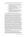
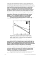
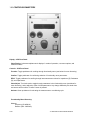
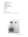
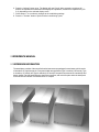
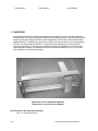
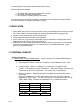
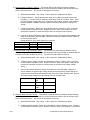
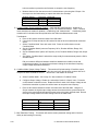
1
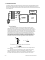
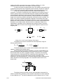
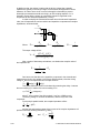
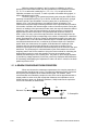
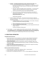
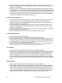
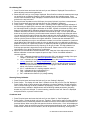
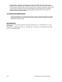
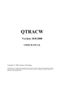
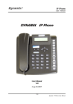
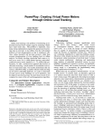
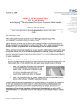
0
0..1
1E
EC
CD
De
ecclla
arra
attiio
on
no
off C
Co
on
nffo
orrm
miitty
y
We: FHC
of:
Europe (TERMOBIT PROD srl)
129 Barbu Vacarescu Str, Sector 2
Bucharest 020272
Romania
declare that:
Equipment: ICM Impedance Conditioning Module
Model: Catalog No.s 55-70-0
Serial Number: ___________
has been designed and manufactured to the following specifications:
IEC61326 Electrical Equipment for Measurement, Control, and Laboratory Uses
I hereby declare that the equipment named above has been designed to comply with the
relevant sections of the above referenced specifications. The unit complies with all essential
Fred
requirements of the Directives.
2008.01.16
Signed by: __________________________________Date:
____________________
09:33:04 Name:
Position:
Frederick Haer
05'00'
President , FHC
Done at: FHC Inc., 1201 Main Street, Bowdoin, ME 04287 USA
Phone: 1207-666-8190, Fax: 207-666-8292
E-mail: [email protected], Website: http://www.fh-co.com
A999.DOC
A999
IMPEDANCE CONDITIONING MODULE
QUALITY INSPECTION SUMMARY
We have made every effort to manufacture this instrument to the highest quality standards. All assemblies
have been thoroughly tested and inspected at the factory as follows:
Initial Assembly Inspection ________
Initial QC Inspection/Calibration ________
24 Hour Burn-In ________
Final Performance Inspection ________
Packaging Inspection
Initials: __________ Date: __________
Items included with any catalog number may be labeled and packaged separately in shipping carton.
Description
Checked
Cat.#55-70-0 ICM Impedance Conditioning Module
Containing:
ICM ________
ICM Accessory Kit ________
A999
IMPEDANCE CONDITIONING MODULE
Quantity
A999
IMPEDANCE CONDITIONING MODULE
“Innovation through collaboration”
Providing Instrumentation and
Apparatus for Cellular Research,
Intraoperative Recording, and
Microneurography; Micro-electrodes,
Micropipettes, and Needles to the
Neuroscience
Community for 30 years.
Impedance Conditioning Module
55-70-0 ICM Impedance Conditioning Module
FHC Headquarters
1201 Main Street,
Bowdoin, ME, 04287 USA
Fax: 207-666-8292
E-mail: [email protected]
www.fh-co.com
24 hour technical service
+1-207-666-8190
1-800-326-2905(US & Can)
FHC Europe
(TERMOBIT PROD srl)
129 Barbu Vacarescu Str,
Sector 2
Bucharest 020272
Romania
L005-18B
A999
IMPEDANCE CONDITIONING MODULE
A999
IMPEDANCE CONDITIONING MODULE
TABLE OF CONTENTS
Manual A999: Impedance Conditioning Module
55-70-0 ICM
0 Declarations
0.1 Declaration Of Conformity
0.2 Conditions For Use
0.3 Symbols Used
1 Operational Manual
1.1 Features
1.2 Description
1.3 Operating Environment
1.4 Inventory
1.4.1 Items Described In This Manual
1.4.2 Additional Items Required For Operation
1.4.3 Replacement Items
1.4.4 Optional Accessories
1.4.5 System Configurations
1.5 Concepts
1.5.1 Terminology
1.5.2 Design Description
1.6 Technical Summary
1.6.1 Specifications
1.6.2 Controls / Connectors
1.6.3 Compatibilities
1.7 Illustrative Procedure
2 Reference Manual
2.1 Reference Information
2.1.1 Packaging
2.1.2 Mounting
2.1.3 Inspection
2.1.4 Power Connections
2.1.5 Warranty
2.1.6 Policies
2.1.7 Service
2.2 Installation
2.3 Functional Checkout
2.3.1 Calibration
2.4 Operational Information
2.5 Scheduled Maintenance
A999
IMPEDANCE CONDITIONING MODULE
A999
IMPEDANCE CONDITIONING MODULE
0.2 CONDITIONS FOR USE
Intended Use
The Impedance Conditioning Module is used to measure the values of impedance, resistance, and
capacitance in microelectrodes. Conditioning modes are intended to fine tune the impedance value of
metal microelectrodes.
Warnings
The Impedance Conditioning Module components should not be disassembled beyond their major
assemblies. Any disassembly beyond this may affect function and calibration. If repair is required
please contact FHC at (207) 666-8190 for evaluation and to secure a return authorization number if
necessary.
Storage Precautions
Store at normal room temperatures between -34°C (-29°F) and 57°C (135°F). Do not expose to
temperatures below -39°C (-29°F) or greater than 70°C (158°F), or a relative humidity of less than 10%
or more than 100%, including condensation, or an atmospheric pressure less than 500hPa or greater
than 1060hPa for long-term storage.
Sterilization
None of the Impedance Conditioning Module components are designed for sterilization. Any attempt to
sterilize them may result in malfunction or component failure.
Handling
While a high degree of durability has been designed into the Impedance Conditioning Module
components, care should be taken not to drop them. Place all cables and leads where they will not be
inadvertently pulled or tangled.
0.3 SYMBOLS USED
USB: This symbol is used to designate a standard USB connection.
A999.DOC
-1-
IMPEDANCE CONDITIONING MODULE
1 OPERATIONAL MANUAL
1.1 FEATURES
• Fast readout of electrode’s impedance, resistance, or capacitance to two or three
digits, depending on range.
• A range of adjustable currents and frequencies allows user to perform electrode
conditioning.
• Provides optional line noise suppression on the measurement signal in noisy
environments.
• Selectable frequency and voltage/current allow measurement of complex electrode
properties, like impedance spectrum, when interfaced to an external computer.
• Intuitive knob and pushbutton control of functionality.
• All necessary cabling included in accessory kit.
• Compact, modular, desktop or rack mountable.
1.2 DESCRIPTION
The ICM Impedance Conditioning Module gives the researcher accurate information about the integrity
and electrical characteristics of metal microelectrodes. User-selectable readings of impedance,
resistance, and capacitance provide a wider range of microelectrode information than has been
previously available. The DSP digital signal processor technology executes complex math algorithms,
providing accurate readings to two significant digits.
Built in adaptive line noise suppression and the driven-shield electrode cable provides seamless
isolation from external noise sources and minimize stray capacitance artifacts in the measurement
signal path. The line noise suppressor operates in continuous measurement mode and is particularly
effective when performing in-vivo impedance measurements.
Electrode conditioning by the end user has been built into the ICM. User-adjustable conditioning
parameters allow removal of small amounts of insulation from the tip to fine-tune electrode impedances
that are found to be a little high.
Settings are manipulated through an intuitive pushbutton and adjustment knob interface. All cabling
necessary comes in the accessory kit. The ICM is a software-upgradeable device. Its firmware is stored
on a FLASH memory that can be re-programmed with the latest code version, available on our support
site www.neurocraft.com.
1.3 OPERATING ENVIRONMENT
The ICM Impedance Conditioning module components have been designed to operate in a typical
laboratory setup. They should be placed on a flat surface that is level and free from contaminants and
vibration.
If the unit is used for in vivo measurement, a power isolation unit is recommended for safety.
A999
- 2 -IMPEDANCE CONDITIONING MODULE
1.4 INVENTORY
1.4.1 ITEMS DESCRIBED IN THIS MANUAL
The following Items are included under the following catalog numbers:
OR
Systems are ordered from the following:
1 ea. Cat. #55-70-0 ICM Impedance Conditioning Module
Includes: ICM Impedance Conditioning Module
ICM Accessory Kit
Includes:
Electrode Conditioning Cable
Rubber feet (use optional)
Calibrated Test Loads
User manual (not shown)
1.4.2 ADDITIONAL ITEMS REQUIRED FOR OPERATION
The following additional items are ORDERED SEPERATELY:
A999
- 3 -IMPEDANCE CONDITIONING MODULE
1 ea. 66-EL-LC-XXX Line Cord (Country specific see sec 2.1.4 of this manual for catalog number)
1.4.3 REPLACEMENT ITEMS
Cat. #55-70-0-01 Electrode Conditioning Cable
Cat. #55-70-0-02 Calibrated Test Loads
1.4.4 OPTIONAL ACCESSORIES
The following accessories are available:
55-11-0 SAF Rack Frame for Stand-Alone Modules
A999
- 4 -IMPEDANCE CONDITIONING MODULE
1.4.5 SYSTEM CONFIGURATIONS
1. ICM Impedance Conditioning Module
2. Electrode Conditioning Cable
3. Electrode Holder
4. Microelectrode
5. KCl bath or similar with reference wire
1.5 CONCEPTS
1.5.1 TERMINOLOGY
Impedance: In the field of microelectrodes, the impedance value is a reference number that relates to
the amount of exposed metal at the tip. The classical definition of impedance as the combination of
resistance, inductance and capacitance of an AC circuit is useful in terms of how the microelectrode test
circuit is designed, however it is not advisable to focus on within the recording circuit.
In broad terms, high impedance produces a more focused recording field that is useful for single unit
recording. The trade-off for this is that as the signal is amplified, so is the noise. A low impedance
electrode is generally quieter, but records from a wider number of neurons without much inherent
selectivity and low amplitude.
The impedance value should be looked at as a reference point to duplicate recording situations that
have proven to provide reliable data quality. See section 1.5.3 for a wider discussion of impedance.
A999
- 5 -IMPEDANCE CONDITIONING MODULE
1.5.2 DESIGN DESCRIPTION
The design is based on the APM hardware design, which contains a 32-bit Digital Signal Processor
(DSP) allowing complex processing of data. Analog circuitry and signal conditioning is reduced to a
minimum, several signal conditioning tasks are being implemented as numerical algorithms that operate
on the digitized data.
R1
Display
V, f
R2
Vd
R3
AOut
R4
Z
AIn1 CODEC
(ADC/DAC)
AIn0
V
Electrode
DSP
Theory of operation
Since the data acquisition is driven by a DSP that can perform complex
mathematical operations, there’s no real need for a constant current generator that
would provide a linear relationship between impedance and output voltage. Instead, a
constant voltage generator can be used and the measurement circuit can be a plain
voltage divider with the electrode as one branch. In fact, the constant-voltage solution
is less sensitive to noise, since the amount of noise picked by the measurement
circuit is lower due to the smaller input impedance. The equivalent impedance of a
current generator is very large, while the impedance of the circuit shown above is
roughly equal to the series resistor (R1 through R4). For illustration purposes, we will
first consider a simple circuit where we neglect parasitic resistors and capacitors.
Vd
Rd
V
V = Vd
Z
Z
Z + Rd
The impedance can be calculated using the following formula:
Z = Rd
V
Vd − V
where Vd is the driving voltage of the divider and V is the voltage measured
on the electrode.
One has to note that by measuring the Vd and V voltages with accurately
paired ADC inputs (like the two inputs of a dual/stereo CODEC), no voltage
calibration is required for the inputs, since the impedance is calculated as a ratio of
two voltages, that is independent of the way they are expressed. Plain numbers
A999
- 6 -IMPEDANCE CONDITIONING MODULE
resulting from ADC conversion (in the range –32768 to +32767, for a 16 bit
conversion) can be used, with no conversion to an actual voltage.
In order to minimize the measurement errors, the resistor Rd will need to have
a resistance of the same order of magnitude as the electrode. Therefore a number of
different resistors (R1 through R4) will be switched using analog switches or relays.
In fact, the electrode impedance has both a resistive and capacitive
component. The inductive components can be neglected on the frequency range of
interest, typically under 10 kHz. Electrodes may have complex models that include
several lumped or distributed resistors and capacitors. Regardless of the complexity
of the electrode model, at any given frequency, it may be reduced to an equivalent
simple circuit containing a resistor and capacitor connected in series or parallel. The
choice of the series or parallel representation depends on the frequency and ratio
between most salient resistive and capacitive elements, or even on the investigator’s
preferences. In many situations, the parallel circuit is the closest representation of the
electrode’s more complex model, therefore it will be considered the basis of our
representation. Impedance can be represented as a complex number, where the
resistive component accounts for the real part and the capacitive reactance for the
imaginary part:
Ce
Rs
Z
Cs
Re
1
1
=
+ jωCe ,
Z Re
Z = Rs +
1
,
jωCs
where ω=2πν, and ν is the frequency of the signal.
The parallel circuit can be converted to its series equivalent, using the
following transformations:
Rs = Re
1
,
1 + ω R e2 Ce2
2
⎞
⎛
1
Cs = Ce ⎜⎜1 + 2 2 2 ⎟⎟
⎝ ω R eC e ⎠
The transformations point to a lower series resistance and a higher series
capacitor, compared to the parallel values.
When calculating the electrode impedance, one has to compensate for the
additional resistances and capacitances in the measurement circuitry. For instance,
the electrode leads may have a negligible resistance, compared to the electrode
contact resistance, but they definitely have a significant stray capacitance Cs. This
capacitance is shunting the electrode signal to ground, particularly at high
frequencies. This stray capacitance Cs is included, along with other components that
will be described in the next paragraphs, in the equivalent measurement circuit,
shown below.
Vd
Rd
V
Rin
Cshnt
Cac
Cstray
Z
The analog circuitry that reads V has an input impedance (composed of a
resistor in parallel with a capacitor), whose resistive component Rin can be neglected
in most instances (>1015 Ω), while its capacitance can be included in the Cstray value.
A999
- 7 -IMPEDANCE CONDITIONING MODULE
In addition to that, the resistor in series with the driving voltage has a parallel
capacitance, typically in the sub-pF range, but that cannot be neglected in certain
instances. In order to have a null net current through the electrode (to prevent
electrolytic processes that would etch the tip), an AC-coupling capacitor Cac is
inserted in series with the output. Its contribution cannot be neglected at low
frequencies for low electrode impedances (<10 kΩ).
In order to simplify the calculations that will return the electrode impedance
value, we will represent the various resistive and capacitive components as complex
impedances, as shown below:
Vd
V
Zd
Zac
Zs
Zd =
Where:
Z
Rd
1 + jω R d C shnt
Zs =
R in
1 + jω R inC stray
Z ac =
1
jω C ac
The output voltage will be:
V = Vd
(( Z + Z ac ) || Z s )
(( Z + Z ac ) || Z s ) + Z d
After a series of elementary calculations, one obtains the complex value of
the impedance as:
Z=
1
− Z ac
Vd − V
1
−
VZ d
Zs
One has to note that due to the capacitive component in the electrode and
measurement circuitry, the voltage V will have a different phase φ than the driving
voltage Vd and can be represented as a complex number:
V = V cos( ϕ) + j V sin( ϕ)
This phase difference φ can be calculated by measuring the delay τ between
the zero-crossing of V relative to the zero-crossing of Vd.
ϕ = 360°
τ
( in degrees )
T
where T is the period of the driving signal (1 ms for a 1000Hz wave).
The driving voltage Vd is taken as reference, and will only have a real
component.
For the simple parallel model, the complex impedance will be:
1
1
=
+ jωCe ,
Z Re
and the real and imaginary parts of the inverse of the complex impedance will
provide us with the following values for Re and Ce :
2
Z
Re =
Re( Z )
A999
and
Ce = −
Im( Z)
ωZ
2
- 8 -IMPEDANCE CONDITIONING MODULE
While the measured voltages V and Vd require no calibration in order to
provide an accurate measurement, the other parameters in the impedance formula
(Zs , Zd , Zac or rather their underlying Cstray , Rd , Cshnt , Cac) are part of the ICM
calibration constants set. However, in order to provide a controlled driving signal, Vd
will be calibrated as well in ICM.
The driving signal (Vd) is synthesized point-by-point using the CODEC DAC
operating at a sample frequency of up to 48 kHz. A table with the points for a single
sine-wave period is pre-calculated in a memory area prior to measurement. For
instance, for a 1 kHz signal frequency, the table will contain 48 samples. The
measurement sequence begins with the generation of the output waveform for about
0.2 seconds, rounded to the nearest integer number of waveform periods. During this
interval, no readings of the input waveform are made, the output is allowed to settle to
a stationary value. After this interval elapses, the input waveform is continuously
digitized with the same rate at which it is synthesized and values are stored in a
buffer. In fact, for every cycle of the output waveform, the data is averaged into the
same buffer, having a length corresponding to the number of samples for a waveform
period. Simultaneously, the driving voltage is digitized and average in the same way,
in a separate buffer, to be used as the reference signal. The data is acquired for the
user-selected measurement time, rounded to the nearest multiple of the waveform
period. When the measurement is complete, ICM calculates the amplitude of the
reference and input and the phase difference by performing a complex Fourier
transform of the signal at the selected waveform frequency for the reference and input
waveforms. The phase angle is calculated based on the ratio between the real and
imaginary parts of the Fourier transform. Using the Fourier method for calculating the
phase angle proved to be much less sensitive to noise as compared to other
methods, like detecting the zero-crossing time. The phase φ, input voltage amplitude
|V| and driving voltage amplitude |Vd| are then used in the equations described above
for calculating and displaying the impedance Z and the Re and Ce values for the basic
parallel equivalent circuit.
1.5.3 A REVIEW OF MICROELECTRODE PROPERTIES
When one chooses the measurement parameters, the complex properties of
microelectrodes should be kept in mind. The electrode impedance greatly varies with
the frequency and amplitude of the measurement signal. For instance, metal
microelectrodes are modeled by complex circuits, which can be approximated with a
simple parallel or series circuit with a particular resistance and capacitance over a
limited frequency range only. Robinson (Robinson, 1968) introduces the equivalent
circuit of an electrode, as shown below:
Ce
en
Electrode Tip
Rs
Rm
Cs
To Preamplifier
Re
A999
- 9 -IMPEDANCE CONDITIONING MODULE
An abbreviated description of the correspondence between various electrical
components and parameters and the physical structures and values would be as
follows:
en is the potential created by a neuron at the location at the electrode
tip; this potential has the value that would be created by the
neuron in the absence of the electrode; the electrode may be in
fact perturbing the actual potential.
Rs is the so called spreading resistance of the saline bath, between
the electrode tip and the null isopotential line.
Ce is the capacitance of the electric double layer formed around the
electrode tip due to electrochemical processes
Re is the leakage resistance due to charge carriers crossing the
electric double layer
Rm is the resistance of the metallic portion of the microelectrode
Cs is the accumulated shunt capacitance to ground from the tip to the
input of the amplifier. This includes the capacitance of the
insulation as well as the capacitance of the wires and connectors
leading from the electrode to the preamplifier
These parameters should not be considered constant, they depend on many
other factors and particularly on the signal frequency. For instance, both the
resistance and capacitance of the double layer vary roughly as 1 ω (Gesteland et
al, 1959). The double layer capacitance has been estimated to be in most common
situations anywhere between 0.18 and 1.0 picofarads per square micrometer of
exposed metal tip (pF/µm2) at a frequency of 1 kHz. For a tip of 100 µm2, (typical of
an electrode having a few MΩ impedance at 1 kHz) the capacitance would be
between 18 pF and 100 pF at 1 kHz, and roughly 3 times larger at 100 Hz. The
spreading resistance of the saline bath is a function of the exposed tip area and
geometry, and can be anywhere between a few hundred ohms and tens of kΩ. The
shunt capacitance of a typical tungsten electrode immersed for a few centimeters in
saline can be as high as 200 pF. This corresponds to a shunt impedance of nearly
0.8 MΩ at 1 kHz. For long electrodes, used for reaching deep brain structures, Cs may
become particularly important. This shunt impedance places a limit on the usable
range of electrode impedances. While some investigators believe that higher
electrode series impedance (the sum of Rs, Rm and impedance of parallel group Ce
and Re) provides better results, which is true in terms of achieving better isolation of
individual neurons, one should keep in mind that this leads to a stronger attenuation
of the signal due to the higher electrode/shunt impedance ratio. In other words, in the
previous numeric example, it won’t be particularly useful to use electrodes having an
impedance much larger than the shunt impedance, i.e. 0.8 MΩ. As a rule of thumb,
the electrode series impedance should not exceed twice the shunt impedance, or the
signal will be greatly attenuated. It is also important that the electrode impedance is
measured in conditions similar to those that will be used during actual recordings, that
is immerse the electrodes in saline for the same depth they will be inserted in the
tissue or tissue and guide tube. In fact one can measure the electrode impedance
with the tip barely making contact with the saline bath, measurement that would give
an indication of the electrode series resistance, and another measurement with it
immersed into saline for a depth matching the recording conditions, in which case one
could figure out what is the contribution of the shunt capacitance. It is advised that the
electrode impedance is checked even under real recording conditions, while inserted
into the preparation or in-vivo.
The measured impedance would not only depend on geometry and recording
conditions, but also on the electrical parameters of the measurement, since
components in the electrode model discussed above may have non-linear
voltammetric or frequency characteristics. Higher measurement currents or voltages
generally result in lower impedance readings. Not only that, but higher currents may
lead to irreversible morphological and electrochemical properties of the electrode,
A999
- 10 -IMPEDANCE CONDITIONING MODULE
resulting in a change of the electrode impedance. In general, high measurement
currents will cause a permanent drop in the electrode impedance. This effect is the
basis of electrode conditioning process, where high AC currents are used to lower the
electrode impedance. This is why the ICM factory default on the measurement current
or voltage is set to 15% of the full scale, and one should use caution with higher
output values. On the other hand, when one applies DC (or very low frequency)
signals to the electrode, in most cases electrolytical processes develop at the
electrode-electrolyte interface, that may result in both an increase or a decrease of
the impedance, depending on the nature of the electrolyte. Passing a DC current
through an electrode immersed in Kohlrausch's solution (3% PtCl, 0.025 N HCl, and
0.025% lead acetate) results in the deposition of spongy colloidal layer of platinum
that increases the tip area, effectively reducing the tip impedance. On the other hand,
passing DC or low-frequency currents through electrodes immersed in many other
electrolytes (e.g. saline) results in an increase of the tip impedance, due to the
deposition of layers of non-conductive material or even to the electrode tip
electrochemical etching, resulting in a reduction of the effective tip area.
The impedance of the electrode strongly depends on frequency. The
frequency variation of the impedance, using typical values for the model components
from Robinson, 1968, is show below:
9
10
Total
Series
Shunt
8
10
7
Z (Ω )
10
6
10
5
10
4
10
1
10
2
10
3
10
ν (Hz)
4
10
5
10
The typical frequency variation of the electrode impedance calculated for Rs=50kΩ,
Ce=50pF at 1kHz, Re=13300MΩ at 1kHz, Rm=100Ω and Cs=100pF. The series
resistance is composed of Rs, Rm, Ce and Re. The shunt impedance is given by Cs.
The total electrode impedance, as measured by ICM, is the series electrode
resistance, in parallel with the shunt impedance.
When measuring the electrode impedance at two different frequencies, for
example 100Hz and 1000Hz with the model parameters used in the above figure, one
should expect a 5.8 times larger impedance reading at 100Hz compared to the value
at 1000Hz. Any direct comparison between the measured electrode impedance in a
lab setting and the nominal impedance claimed by the electrode manufacturer must at
least take into account the frequency of the signal and, for high impedance
electrodes, where the shunt capacitance is significant, the immersion depth. In this
latter case, the stray capacitance of the measurement leads may be significant. While
the ICM implements guarded shields and digitally compensates for the stray
capacitance, any additional wires or connectors may add to the stray capacitance and
influence the impedance reading. As the factory measurement conditions may be
different from vendor to vendor, any comparison of electrode impedances across
vendors must be made taking into account these differences.
The phenomena taking place while recording through metal microelectrodes
are so complex that Robinson concludes that "description of the elements of
A999
- 11 -IMPEDANCE CONDITIONING MODULE
microelectrode recording makes it possible to understand, however crudely and
approximately, which elements are important, which are unimportant (...).
Unfortunately, knowledge of these qualities does not permit one to tell" in detail "how
a given electrode will perform in brain tissue". ICM attempts to provide investigators a
tool that would give a more accurate indication of various electrode components
values, for evaluation and better understanding of the electrode properties and their
performance for recording.
1.6 TECHNICAL SUMMARY
1.6.1 SPECIFICATIONS
ICM:
Measurement Accuracy: +-5% actual. Displayed to 2-3 digits, depending on range.
Measurement Applied Voltage: Adjustable 10% - 100% of 1.75Vpp sine wave, Default is 20%
Measurement Frequency: Adjustable from 50Hz to 4kHz
Impedance Range: 1kΩ to 100MΩ
Conditioning Voltage Range: Adjustable 10% - 100% of 3.5Vpp sine wave, Default is 100%
Conditioning Current Frequency: Adjustable from 50Hz to 4kHz
Display: 8 characters, 1cm height, red
Power Requirements: 100-240 VAC, 50-60Hz
Dimensions:
Height:
13cm (5.22")
Width:
10cm (4.20")
Length:
25cm (9.75")
Weight: 1.48 Kg (3.26 lbs)
Mounting Options: Tabletop, 4 rubber feet prevent sliding.
Rack mountable with SAF Rack Frame (Cat. #55-11-0 Available separately)
Computer Interface: High-speed USB 2.0, backwards full-speed USB 1.1 compatible.
(Computer needed for FLASH upgrade only)
A999
- 12 -IMPEDANCE CONDITIONING MODULE
1.6.2 CONTROLS/CONNECTORS
Display – ICM Front Panel:
Value Display: 8 character alphanumeric display of: modes of operation, user menu options, and
measured values.
Controls - ICM Front Panel:
Function: Toggle pushbutton for scrolling through functionality menu (see below for menu hierarchy).
Confirm: Toggle pushbutton for confirming selection of functionality menu parameters.
Z/R/C: Toggle pushbutton for scrolling through last measurement values for Impedance (Z), Resistance
(R), and Capacitance.
Value Adjust: Turn knob used to toggle through parameters in the functionality menu (see below for
menu hierarchy), and to adjust the value of those parameters. Any change affected by this knob does
not become active until the "Confirm" button is pressed.
Activate: Green pushbutton for activating the measurement or conditioning cycle.
Functionality Menu Hierarchy:
Measure
Frequency (50-4000Hz)
Duration (200 - 20000ms)
A999
- 13 -IMPEDANCE CONDITIONING MODULE
Range (10k, 100k, 1M, 10M, Auto)
Differential (On, Off)
Output (10%-100% output voltage)
Filter (On, Off)
Conditioning
Frequency (50-4000Hz)
Duration (200 - 20000ms)
Range (10k, 100k, 1M, 10M, Auto)
Output (10%-100% output voltage)
Calibrate
ADC (0-100M)
DAC (0-100M)
Settings
Default
Save
Fact Cal
Connections - ICM Front Panel:
Electrode: 6 pin DIN socket for interfacing the Electrode Conditioning Cable.
A999
- 14 -IMPEDANCE CONDITIONING MODULE
Controls - ICM Rear Panel:
0|I: Rocker switch used to activate power.
Connections - ICM Rear Panel:
Power: 3 prong inlet for interfacing line cord to internal universal power supply.
USB: High speed USB 2.0 port for interfacing with a host computer. (Custom applications only)
1.6.3 COMPATIBILITIES
The ICM Impedance Conditioning Module will perform measurement and conditioning on
microelectrodes offered by other manufacturers. Since the circuitry performing the measurement is
likely to be different than that used in the manufacturing of the microelectrodes, a different value
may be obtained than provided by the manufacturer.
1.7 ILLUSTRATIVE PROCEDURE
Measuring Impedance/Resistance/Capacitance
1. Connect leads: Black – Electrode, Red – Reference, Green – Common ground
2. Lower electrode tip in electrolyte solution approx. 1mm.
3. Press the “Activate” button once. The display will read “Meas…” while processing, and then
display the impedance (Z) measurement (default) or the last measurement type used (impedance,
equivalent resistance, or equivalent capacitance).
4. Pressing the “Z/R/C” button toggles through the last measured values of impedance Z, resistance,
R, or capacitance, C.
Conditioning Microelectrodes
1. Set up cable and immerse electrode.
2. Press the “Function” button to display the currently selected function and rotate the “Value Adjust”
to toggle through the available functions (Meas., Cond. etc) until “Cond” is displayed. Press
“Confirm” to select conditioning mode and adjust its parameters (frequency, duration, output
current). The display will switch to “Freq” (frequency), which is the first conditioning parameter.
3. Rotate the “Value Adjust” knob if you want to select a different conditioning parameter.
4. Press “Confirm” to display the current parameter value or change it. To change the current value,
turn the “Value Adjust” knob. When done, press “Confirm” to accept the displayed value. For
instance, when adjusting the frequency, the ICM with briefly display “Freq Set” and will then go
back to the parameter selection menu, displaying “Freq”. To cancel the change, press “Function”.
The display will switch back to “Freq”.
5. When back in the parameters selection menu, rotate the “Value Adjust” knob to select a different
parameter for the conditioning (duration, output), then use the same procedure as described at
previous step for the adjustment of the parameter value.
A999
- 15 -IMPEDANCE CONDITIONING MODULE
6. Press the “Activate” button once. The display will read “Cond” while processing, and then will
perform an impedance measurement and display the impedance, resistance or capacitance (Z, R
or C) depending on the selected display mode.
7. Follow steps 3 – 4 to make any changes to the conditioning settings.
8. Press the “Activate” button to perform further conditioning cycles.
2 REFERENCE MANUAL
2.1 REFERENCE INFORMATION
The stand-alone modules of the neuroCraft series instruments are packaged in metal cases, which consist
of standard 5.25" high front panels. Front panel widths are specified as Type 2 modules (2.05" actual), Type
4 modules (4.15" actual), and Type 6 modules (6.25" actual) Front panels are mounted on extruded top and
bottom panels. Flat side panels slide into slots in the extrusions, and are held in place when the back panel
is secured into the extrusion. All modules are 9.75" in depth.
A999
- 16 -IMPEDANCE CONDITIONING MODULE
Type 2 Module
Type 4 Module
Type 6 Module
2.1.2 MOUNTING
All stand-alone modules are completely encased and can be used without further mounting or hardware.
Provided rubber feet may be used to protect surfaces from scratching. However, it may be suitable to group
modules, and we have made provision for several configurations. The SAF Rack Frame for Stand-Alone
Modules (cat #55-11-0) will hold up to eight Type 2 modules, four Type 4 modules, or two Type 6 modules
and 2 ea. Type 2 Dress Panels (cat #55-11-1 use optional), while occupying only 3 rack units (5.25")
vertically on a standard 19” instrument rack. Several combinations are available for all of the neuroCraft
series stand-alone modules. For example an SAF frame could accommodate 3-Type 2, 1-Type 4, and 1Type 6 within its 16" of horizontal rack space.
SAF Rack Frame For Stand-Alone Modules
(Shown with a neuroCraft Type 2 Module)
Dress Panels for SAF (Ordered Separately):
• 55-11-1 Type 2 Dress Panel
A999
- 17 -IMPEDANCE CONDITIONING MODULE
2.1.3 INSPECTION
FHC Modules are factory checked and calibrated but should be carefully inspected upon receipt,
before using, or activating power. If any exterior damage to the shipping carton is noted, the
instrument(s) should be inspected for obvious physical damage. The contents of each package
should be physically checked against the inventory list (sec. 1.3) to determine shortages or errors in
inventory.
2.1.4 POWER CONNECTIONS
All of the stand-alone modules in the neuro/craft series are powered by an internal universal power
supply that accepts inputs of 85-265VAC, 50-60Hz. An international pattern Line Cord (not shown) is
ordered separately, and is specified by country per the catalog number. (See table below for catalog
numbers.)
66-EL-LC-AUS
66-EL-LC -CH
66-EL-LC -DAN
66-EL-LC -EURO
66-EL-LC 5-ISR
66-EL-LC 5-ITA
66-EL-LC -JA
66-EL-LC -SAF
66-EL-LC -SWI
66-EL-LC -UK
66-EL-LC -USA
Australia
China
Denmark
Europe
Israel
Italy
Japan
South Africa
Switzerland
United Kingdom
North America
2.1.5 WARRANTY
All FHC products are unconditionally guaranteed against defects in workmanship for one year from
date of shipment as long as they have been exposed to normal and proper use. Although the oneyear warranty may have expired, please contact our Service Department before attempting any
repairs or alterations. Many of these repairs will still be performed at the factory at no charge to the
customer.
2.1.6 POLICIES
1. TECHNICAL SUPPORT: It is our policy to provide our customers with the most comprehensive
technical support in the industry. If any questions arise or problems occur, we encourage you to call
or write and we promise to promptly and comprehensively respond to your requirements.
2. TRADE-UP POLICY: It is our policy to offer customers trade-up ability as new and/or expanded
capabilities for their instruments are announced. In many cases, full credit will be given. In general,
we will allow 100% credit for two years and depreciate 20% per year thereafter. Please contact our
Marketing Department for information relating to your particular situation.
2.1.7 SERVICE
Should service be required, please contact our Service Department for a return authorization number
and instructions (207-666-8190). Please have the model and serial number on hand (Both are located
A999
- 18 -IMPEDANCE CONDITIONING MODULE
on the back panel). Carefully pack the instrument before returning.
Please include a note indicating:
1. The model number and purchase date of the instrument
2. The person to contact if questions arise
3. The "symptoms" indicating that repair is necessary
If the instrument is not covered by the warranty, a quotation will be forwarded to the sender detailing
the repairs necessary and charges, before repair is begun.
2.2 INSTALLATION
1. Attach rubber feet to bottom corners of the ICM if mounting on a desktop. If rack-mounting in the SAF
Rack Frame, install the device and tighten the front panel thumbscrew before plugging in any
cabling.
2. Plug the line cord into the power outlet on the back panel.
3. Plug the electrode cable into the jack on the front panel.
4. Power up the unit. It will go through a "Wait USB" routine (for applications requiring USB) and then
the display will read "Z Check". Unit is now ready for use.
5. Route cable so it can't be inadvertently pulled or tangled, and connect the black pin to the electrode,
the red pin to the bath and the green clip to common ground. If using differential mode, connect
green clip to reference electrode.
2.3 FUNCTIONAL CHECKOUT
Functional Checkout:
1) Measure Mode “Impedance Measurement” – Verify the accuracy of Impedance Measurement by
performing the following steps below.
a. Selecting Measure Mode - Rotate the “value adjust “ knob for “Measure” menu. Press
confirm key to enter menu.
b. Configure Range – While in the “Measure” menu rotate the “value adjust” knob for
“Range”. Press confirm key to enter “Range” menu. While in the “Range” menu rotate the
“value adjust” knob for first range to test. Press confirm key to accept setting.
c.
A999
Measure Impedance – Place the first resistor to be tested matching the range set in the
above step.
Record in the table below the value of the resistors Z & R value (the Z & R values are
toggled by the “Z/R/C” switch). You will use a precision 1% tol resistors for values of 10K,
100K, 1Meg & 10Meg. Remember to repeat steps “b” & “c” for each range tested.
Value / Range
10K
100K
1M
10M
Expected
Value = +/- 5%
Value = +/- 5%
Value = +/- 5%
Value = +/- 5%
Measure
Auto Range
10M
Expected
Value = +/- 5%
Measure
- 19 -IMPEDANCE CONDITIONING MODULE
2) Measure Mode “Frequency Testing” - This section will include testing of frequency settings.
Basically the test is to set the parameter and verify that what we measure with an O-Scope is the
same as what we set it to. We will use a 10K resistor for this test.
a. Select Measure Mode - Like in step “1” above select the “Measurement” Menu.
b. Configure Duration - Set the duration to a longer time to allow for measurement of the
frequency. To set the Duration rotate the “value adjust” knob for “Duration” menu. Press
the confirm button to select this menu. Rotate the “value adjust” knob for a long duration
between 6000ms to 9999ms (enough to perform frequency measurement with your OScope)
c.
Configure Frequency - Rotate the “value adjust” knob for “Frequency” menu. Press the
confirm button to select this menu. Rotate the knob for each of the frequencies to test
listed below remember to press the confirm button to accept the new frequency.
d. Using an O-Scope measure the signal frequency across a 10K resistor placed between the
black & red terminal of the ICM cable. Record the frequency measure for each frequency
to test in the table below.
repeat steps 2c & 2d for each frequency to measure
Frequency to Test
Expected
Measured
100 Hz
+/- 5%
1K Hz
+/- 5%
4K Hz
+/- 5%
3) Measure Mode “Output Voltage Testing” - This section will include testing of Measure output
voltage settings. Basically the test is to set the parameter and verify that what we measure with an
O-Scope is the same as what we set it to. We will use a 10K resistor for this test.
a. Select Measure Mode - Like in step “1” above select the “Measurement” Menu.
b. Configure Output Voltage - Rotate the “value adjust” knob for “Output” menu. Press the
confirm button to select this menu. Rotate the knob for each of the Output Voltage to test
listed below remember to press the confirm button to accept the new Output Voltage
setting.
c.
Place a 10K resistor between the black & red terminal of the ICM cable. Using an OScope measure the signal output voltage across the resistor with the ground lead of the
scope on the red electrode lead and the scope probe to the black electrode lead. Record
the output voltage measure for each setting to test in the table below.
Output Setting
100%
50%
10%
Expected
Vpp
1.4 – 1.7
Measured
½ of
100%
.1 x
100%
4) Measure Mode “Duration Testing” - This section will include testing of Measure duration settings.
Basically the test is to set the parameter and verify that what we measure with an O-Scope is the
same as what we set it to. We will use a 10K resistor for this test.
a. Select Measure Mode - Like in step “1” above select the “Measurement” Menu.
b. Configure Duration setting - Rotate the “value adjust” knob for “Duration” menu. Press the
confirm button to select this menu. Rotate the knob for each of the Durations to test listed
A999
- 20 -IMPEDANCE CONDITIONING MODULE
below remember to press the confirm button to accept the new frequency.
c.
Measure the time from the start to end of a measurement cycle using the O-Scope. Set
the scope to a time base setting to capture the entire time envelope.
Duration Setting
4000 ms
2000 ms
1000 ms
Expected
+/- 25%
+/- 25%
+/- 25%
Measured
5) Condition Mode “Signal Generation Testing” – Verify that the signal frequency, amplitude &
duration is different between the Conditioning Mode and Measurement Mode. Note: Condition
mode exercises two modes of operation, “conditioning” and “measurement”. Conditioning mode
remains until it’s duration time has expired before the ICM enters Measurement mode.
Test Method –
a. Place a 10K resistor across the leads of the ICM cable.
b. Connect an O-Scope across the 10K resistor like that of other measurements mentioned
above.
c. Select “Condition Mode” from main menu level. Press the confirm button to enter
Condition Menu.
d. Set the “Condition Mode” parms as Frequency 2K hz, Duration 4000ms, Range 10K,
Output 100%
e. Set the “Measure Mode” parms as Frequency 1K hz, Duration 2000ms, Range 10K, Output
20%
f. Set ICM for “Condition Mode” and with the scope ready for measurements press the ICM’s
Activate Button.
Did you notices a difference between waveforms between the condition mode and
measurement modes? You should have witness a change in the waveform frequency,
output voltage amplitude and duration.
6) Condition Mode “Output Voltage Testing” - This section will include testing of Condition output
voltage settings. Basically the test is to set the parm and verify that what we measure with an OScope is the same as what we set it to. We will use a 10K resistor for this test.
a. Select Condition Mode - Like in step “5c” above select the “Condition” Menu.
b. Configure Output Voltage - Rotate the “value adjust” knob for “Output” menu. Press the
confirm button to select this menu. Rotate the knob for each of the Output Voltage to test
listed below remember to press the confirm button to accept the new frequency.
c.
Place a 10K resistor between the black & red terminal of the ICM cable. Using an OScope measure the signal output voltage across the resistor with the ground lead of the
scope on the red electrode lead and the scope probe to the black electrode lead. Record
the output voltage measure for each setting to test in the table below.
Output Setting
100%
50%
10%
Expected sinewave
Vpp
3.00 - 3.6
1.5 – 1.88
300mV – 368mV
Measured
7) Misc Parameter Testing - This section will test the remain parameter setting and it’s function.
Ability to retain settings in memory.
A999
- 21 -IMPEDANCE CONDITIONING MODULE
a. Diff Mode – The Differential Mode setting is found in the Measurement Mode menu
selection. The Diff Mode allows alternate grounding reference connections.
i. By default the Diff Mode is set to “off”. Change this to “on” and press the confirm
key. Place a 10K 1% resistor between the red and black leads of the electrode
measurement cable.
ii. Next while in Measurement Mode press the activate button. You will now see an
impedance measurement different than an expected 10K due to the internal
removal of ground reference via the relay controlled by Diff Mode.
iii. Connect the Ground to the Red lead of the ICM cable with 10K resistor still
between the Red and Black lead. Press the activate button and should get an
expected 10K measurement.
Set the Diff Mode back to “off” setting.
Did Diff Mode testing pass?
b. Saving Configuration Settings Test - This section will test the retention of parameter
setting to NV Flash Ram. All that is required is to set only a few settings to determine that
they have been retained.
i. Change any parameter setting from within Measure or Cond modes. Remember
to press the Confirm button to accept any changes.
ii. Select the Settings Menu and press confirm at the Save prompt.
iii. Turn off the ICM then back on after 10 sec.
iv. Return to the Measure or Cond mode where you made changes and note that your
change is still there.
Did Saving Configuration Settings pass?
8) Test Complete - You have completed the functional check out of the ICM. Please remember to
reset configuration change. A quick method to reset configuration changes is to turn the ICM off
for 10 Sec then back on. Note! Configuration changes are saved only if you select “Settings” then
save them. For the purpose of functional testing we did not save any of the settings.
2.4 OPERATIONAL INFORMATION
Setting Measurement Parameters
1. Press Function button. If the unit was last left in measurement mode, display will read “Measure”.
Press Confirm button to access measurement parameters. If a different function is displayed,
rotate Value Adjust knob until display reads “Measure”, then press Confirm button to access
measurement parameters.
2. Once the Confirm button is pressed, the last parameter viewed will be displayed. Rotate Value
Adjust knob to toggle through the parameters (Frequency, Duration, etc). Press the Confirm button
to access the setting.
3. Use the Value Adjust knob to dial in the setting, press the Confirm button to apply the new setting.
Display will return to the parameter selection menu.
4. Press the Function button once to return to the main display.
Measuring Impedance/Resistance/Capacitance
1. Connect leads: Black – Electrode, Red – Reference, Green – Common ground
2. Lower electrode tip in electrolyte solution approx. 1mm.
3. Confirm that unit is in Measurement mode. A "Z", "R", Or "C" will be displayed in the leftmost digit.
A999
- 22 -IMPEDANCE CONDITIONING MODULE
4. Press the “Activate” button once. The display will read “Meas…” while processing, and then
display the impedance (Z) measurement (default) or the last measurement type used (impedance,
resistance, or capacitance).
5. Pressing the “Z/R/C” button toggles through the last measured values of impedance Z, resistance,
R, or capacitance, C. If the value is out of range or the measurement is presumed inaccurate, the
display will blink. For instance, when reading a 100k impedance on a manually selected the range
of 10 MΩ, the measured impedance will still be displayed, and may be close to the actual one, but
the display will be blinking to indicate that the range is inappropriate for the measured impedance
value, and the accuracy of the measurement may be poor.
Setting Conditioning Parameters
1. Press Function button. If the unit was last left in manual condition mode, display will read “Cond”.
Press Confirm button to access conditioning parameters. If a different mode is displayed
(Measure, Plating, etc), rotate Value Adjust knob until display reads “Cond”, then press Confirm
button to access conditioning parameters.
2. Once the Confirm button is pressed, the last parameter viewed will be displayed. Rotate Value
Adjust knob to toggle through the parameters (Frequency, Duration, Output). Press the Confirm
button to access the setting.
3. Use the Value Adjust knob to dial in the setting, press the Confirm button to apply the new setting.
Display will return to the parameter menu.
4. Press the Activate button once to return to the main display or wait 5 seconds.
Conditioning Microelectrodes
1. Set up and measure electrode impedance.
2. Press Function button and set the manual conditioning parameters as above.
3. Press the Activate button once. The display will read “Cond” while processing through a condition
cycle followed by a measurement cycle, and then display the new impedance (Z) measurement
4. Pressing the “Z/R/C” button toggles through the last measured values of impedance Z, resistance,
R, or capacitance, C. indicated by the third display digit.
5. Continue conditioning by repeated pressings of the Activate button. To change the parameters
after any cycle press the Function button and continue as described above.
Saving Settings
1. Press Function button and rotate the knob until you see “Settings” displayed.
2. Press Confirm. The display will read “Save”. Press Confirm again to select saving the settings, or
rotate the knob to select a different subfunction (restoring settings or factory calibration). When
save is selected, ICM will prompt the user to confirm saving the current settings as power-up
defaults by displaying “Confirm”. Press “Confirm” again to save the settings to the non-volatile
memory (NVRAM). All measurement and conditioning-related parameters are saved to NVRAM.
To cancel saving, rotate the knob until “Cancel” is displayed and press Confirm, or press Function
button.
Restoring Settings
1. Press Function button and rotate the knob until you see “Settings” displayed.
2. Press Confirm. The display will read “Save”. Rotate the knob until you see “Defaults” displayed.
Press Confirm again to select restoring the settings to their factory defaults. ICM will prompt the
user to confirm restoring the current settings to their defaults by displaying “Confirm”. Press
“Confirm” again to restore the settings. All measurement and conditioning-related parameters are
reset to their factory defaults. The calibration is not reset to its factory default. To cancel saving,
rotate the knob until “Cancel” is displayed and press Confirm, or press Function button.
A999
- 23 -IMPEDANCE CONDITIONING MODULE
Re-calibrating ICM
1. Press Function button and rotate the knob until you see “Measure” displayed. Press confirm to
select adjusting measurement parameters
2. Rotate the knob until you see “Range” displayed. Press Confirm to select the measurement range
you would like to re-calibrate. Rotate the knob to toggle through the available ranges. Press
Confirm when the desired range is displayed. Press Function to exit the measurement menu and
go back to the top level menu.
3. Connect a known impedance at the ICM input, then press “Activate” to perform a measurement.
4. Press Function button and rotate the knob until you see “Calibration” displayed.
5. Press Confirm. The display will read “Cal ADC”. Pressing Confirm again will select calibration of
the ICM analog-to-digital (ADC) converter and will display the last measured Z/R/C value. Rotate
the ValueAdjust knob to change the calibration of the ADC. ICM will re-calculate the Z/R/C value
based on the updated ADC calibration and display the result. Rotate the knob until the ICM
indication will match the value of the impedance connected at the input. You can press Activate
button at any time for performing a new measurement instead of using the last measured values.
You can press Confirm again to accept the change and save the value to NVRAM or Function to
reject it. Canceling the change will not restore the original value of the calibration constant, you will
need to cycle the power to restore the original calibration. Please note that calculated Z/R/C
values are dependent not only on one calibration constant, but on all the constants for a particular
range. Making the ICM indication match the value by adjusting only one calibration constant at a
particular frequency for a particular (resistive or capacitive) load will not guarantee that the ICM will
perform a correct measurement at any frequency for all type of loads. The ICM calibration is a
multi-step process that is beyond the scope of this manual. Please contact a FHC technical
representative if you think ICM requires a re-calibration.
6. When back to the calibration constant selection menu, rotate the Value Adjust knob to select a
different calibration constant and repeat the previous step. The list of available calibration
constants include:
a. ADC – calibrates the analog-to-digital converter ADC, such that the reading of the input
voltage V described in the Theory of Operation section is correct.
b. Vout – calibrates the output voltage Vd (please refer to the model of the measurement
circuitry described in the Theory of Operation section)
c. Iout – calibrates the maximum output current, i.e. the current that will pass through Rd
when ICM input is shorted. Please note that changing the DAC calibration, described
below, will require a re-calibration of Iout.
d. AC C – calibrates the AC- coupling capacitor value Cac
e. Shnt – calibrates the shunt capacitance Cshnt
f. Cap – calibrates the stray capacitance Cs
g. Ref – calibrates the reference (Vd) voltage reading
Restoring Factory Calibration
1. Press Function button and rotate the knob until you see “Settings” displayed.
2. Press Confirm. The display will read “Save”. Rotate the knob until you see “Fact Cal” displayed.
Press Confirm again to select restoring the calibration to its factory defaults. ICM will prompt the
user to confirm restoring the factory calibration by displaying “Confirm”. Press “Confirm” again to
restore the factory calibration. Measurement and conditioning-related parameters (frequency,
duration etc) will not be affected. To cancel restoring, rotate the knob until “Cancel” is displayed
and press Confirm, or press Function button.
Continuous mode
1. Press Function button and rotate the knob until you see “Meas” or “Cond” displayed.
2. Press Confirm. Rotate the knob until you see “Duration”. Press Confirm again to select adjusting
the measurement or conditioning duration and rotate the knob to select measurement duration of
less than 200ms. When turning the knob past the minimum 200ms value, “Cont” will be displayed.
Press “Confirm” again to select the continuous measurement/conditioning mode. In this mode, the
measurement will not have a fixed duration, but will be performed continuously, as long as the
A999
- 24 -IMPEDANCE CONDITIONING MODULE
Activate button is held down. During the measurement, the Z/R/C value will be continuously
updated, until the Activate button is released. In continuous mode, the line noise filter is active. In
the fixed duration mode the filter cannot be activated, since it requires a continuous measurement
in order to learn a replica of the line noise and subtract it from the signal. Please note that an
extended measurement time, particularly when using a high output current, may result in a
decrease of the electrode impedance.
2.5 SCHEDULED MAINTENANCE
A yearly performance of the Functional Checkout in section 2.3 should be performed to ensure
function and calibration. If the unit fails any part of this functional test, contact the FHC Repair
Department at (207)666-8190
REFERENCES
Robinson, D.A.: The electrical properties of metal microelectrodes. Proc. of the IEEE, 56 Nr. 6, 10651071 (1968)
Gesteland, R.C., Howland, B., Lettvin, J.Y., and Pitts, W.H.: Comments on microelectrodes, Proc. IRE,
vol. 47, pp. 1856-1862 (1959)
A999
- 25 -IMPEDANCE CONDITIONING MODULE