1
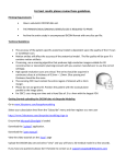
Description
Warnings
The WayPoint™ System Implantation Kit (66-WP-IK) includes the following items, each
available as a replacement part:
(1)
(1)
(1)
(1)
(1)
(4)
(4)
(4)
(1)
(1)
WayPoint™ Sterilization and Storage Case
WayPoint™ Hex Wrench
WayPoint™ Manual Driver Handles
WayPoint™ Combination Driver Bit
WayPoint™ Assist Drill Bit
WayPoint™ Anchors 5mm (pkg of 3)
WayPoint™ Anchor Plugs (pkg of 3)
WayPoint™ Locator Pins (pkg of 3)
Osteomed 1.2mm Pilot Drill
Osteomed Single Use Sterile Power Driver
66-WP-SC
66-WP-HW
66-WP-DH
66-WP-CD
66-WP-DB
66-WP-AN5
66-WP-AP
66-WP-LP
68-OM-PD
68-OM-SD
Note that the following components within this kit are single use items:
66-WP-AN5, 66-WP-AP, 66-WP-LP, 68-OM-PD, and 68-OM-SD.
• Do not drill or install anchors in bone that is less than 4.5mm thick, or in bone that is
weakened or diseased.
• Do not use anchors that exhibit any sign of looseness. Replace anchors and rescan
•
•
•
•
if necessary.
A WayPoint™ Locator Pin must be screwed in to the depth of its built in stop to
provide accurate registration.
WayPoint™ Locator pins may come in contact with non-sterile items during scanning procedures. Wipe locator pins and the area around the wounds with antiseptic
before the hex wrench and combination driver are applied for locator pin removal.
Do not allow WayPoint™ Anchors to remain implanted for more than 28 days.
Follow appropriate warnings when using accessory drills.
WayPoint™ Anchor/
Locator Implantation Kit
WayPoint™ is a trademark of FHC, Inc.
L011-40 (Rev. F0, September 2010)
Cautions
• For the most secure fit of the WayPoint™ Anchors, advance drill and driver tools as
Optional Accessory
WayPoint™ Anchors 4mm (pkg of 3)
66-WP-AN
Indications for Use
The WayPointTM Stereotactic System is intended to be used with commercially available
stereotactic systems for neurosurgical procedures which require the accurate positioning
of microelectrodes, stimulating electrodes, or other instruments in the brain or nervous
system.
Intended Use
The WayPoint™ Anchor/Locator System is intended for use with the WayPoint™ Platform and Drive Systems, in conjunction with VoXim® microTargetingTM and WayPointTM
Planner.
The WayPoint™ Anchor/Locator System provides tools and components for the implantation of anchors to be used as mounting sets in WayPoint™ Platform based surgical
procedures.
perpendicular to the skull as possible, and do not permit them to ‘wobble’ during
advancement.
• Avoid over tightening anchors, pins and plugs, as this can strip bone, shear an
anchor, or otherwise damage components.
• Instruct the patient to avoid situations that could affect or disrupt the implanted
anchors and to be cautious about infection.
• Always use the WayPoint™ Hex Wrench to secure anchors when installing or
removing pins or plugs.
Scanning
WayPoint™ Anchors, Anchor Plugs, and Locator Pins are CT visible. The patient’s
head must be kept immobile while being scanned. Ensure that all Locator Pins are
completely within the scan field of view.
CT Scan requirements:
Contiguous slices; no gaps between slices
No overlapping slices
Slice thickness no greater than 1.25mm
Pixel size less than 1mm (0.5 to 0.8mm for best results)
Gantry tilt angle of zero
The tools and components of the WayPoint™ System do not change the indications for
use of the WayPoint™ Stereotactic System.
Non-clinical testing demonstrated that the WayPoint™ Anchors are MR Conditional. A patient with this device can be scanned safely immediately after
placement under the following conditions:
Sterility
The WayPoint™ Anchor/Locator System components must be sterilized prior to each use.
• Steam Protocol:
Sterilizer Type:
Preconditioning Pulses:
Minimum Temperature:
Full Cycle Time:
Minimum dry time:
Configuration
• Sterrad Protocol
Prevacuum
3
132°C (270°F)
8 minutes
40 minutes
Wrapped
Sterrad 100S full cycle
Tools must be thoroughly cleaned, using a disinfectant solution, and then wiped with a
distilled water dampened cloth after each use, prior to re-sterilization.
WayPoint™ Anchors, Plugs, and Pins are single use items and must be disposed of
appropriately after use.
MR Scan requirements:
Static magnetic field of 3-Tesla or less
Maximum spatial gradient magnetic field of 720-Gauss/cm or less
Maximum whole body averaged specific absorption rate (SAR) of 2.9-W/kg for
15 minutes of scanning
MR image quality may be compromised if the area of interest is in the exact same area
or relatively close to the position of the WayPoint™ Anchor. Therefore, optimization
of MR imaging parameters to compensate for the presence of this device may be
necessary.
Rx only. CAUTION: Federal law (USA) restricts this device to sale by or on the order of a physician.
See platform technical source manual for complete CT and MR scanning parameters.
“Innovation through collaboration”
Copyright Notice: The contents of this manual are the property of FHC, Inc. Any reproduction in whole
or in part is strictly prohibited.
Disclaimer: FHC, Inc. does not accept liability for injury or damage to equipment that may result from
misuse of the microTargeting™ Drive system or its components.
European Conformity. This device fully complies with MDD Directive 93/42/EEC and legal
responsibilities as a manufacturer are with FHC, Inc. 1201 Main Street, Bowdoin, ME 04287 USA
FHC, Inc.
1201 Main Street
Bowdoin, ME 04287 USA
Fax +1-207-666-8292
E-mail: [email protected]
www.fh-co.com
24 hour technical service:
1-800-326-2905 (US & Can)
+1-207-666-8190
FHC Europe
(TERMOBIT PROD srl)
129 Barbu Vacarescu Str,
Sector 2
Bucharest 020272
Romania
WayPoint™ Anchor/Locator System
Implantation Kit
Illustrative Procedure
Figure 1: Application of Driver to Anchor through Wrench
Figure 5: Application of Plug to Anchor
Directions For Use
• Follow aseptic technique throughout. The implant procedure does not need to be done in
an OR setting.
• Mark the intended anchor points on the patient’s scalp (see the WayPoint™ Platform
User Manual for placement guidance).
• Assemble drill and driver tools.
• Using local anesthesia, for each anchor installation:
Figure 2: Application of Anchor to Patient
◊ Create
an 10-15mm incision through scalp and muscle tissue and scrape the
pericranium from the anchor site.
◊ If
desired, use the Assist Drill to create a pilot hole. Alternately, use the Power Driver
and Pilot Drill Bit to create a pilot hole. When using the Power Driver, refer to the
Osteomed AutoDriver™ Battery Powered Screw Driver Product Information and
Instructions for Use for safe operation of the device.
◊ Attach
Figure 6: Removal of Plug from Anchor
an anchor to the wrench and driver tools (figure 1).
◊ Install
the anchor in the skull with a clockwise rotation of the wrench and driver tools
(figure 2).
◊ Use
the wrench to support the anchor while twisting the driver counterclockwise out
from the anchor (figure 2). If using the WayPoint™ PosiDriver, lift straight up once the
anchor is seated and the driver has disengaged.
◊ Use
the wrench to support the anchor while twisting a locator pin clockwise into the
anchor with the driver tool (figure 3).
Figure 3: Application of Locator Pin to Anchor
◊ Carefully
pull the driver and wrench from the anchor (figure 3). Note that the Power
Driver should not be used to install locator pins.
◊ Inspect
the attachment of the anchor to the skull and the pin to the anchor. Locator
pins must be screwed in to the depth of their built in stop. Anchors must be tight.
Replace stripped anchors in a new location.
• Repeat the anchor installation procedure for all anchor sites and any additional sites
where a locator is desired.
• Scan the patient.
• Wipe locator pins and the area around the wounds with antiseptic before pin removal.
• Use the wrench to support anchors while removing pins (figure 4).
• Use the wrench to support anchors while installing plugs (figure 5).
• Stitch and bandage anchor site wounds appropriately.
• Use the wrench to support anchors when removing plugs prior to mounting a
microTargeting™ Platform during an surgical procedure (figure 6).
Figure 4: Removal of Locator Pin from Anchor