1
School of Computing, Engineering and
Physical Sciences
Sergio Zapatel
Interactive Ultrasonic
Guided System
(EL3990)
Submitted in partial satisfaction of the
requirements for the degree of
Bachelor of Engineering (with Honours)
in
Electronic Engineering
April 2011
I declare that all material contained in
this report, including ideas described in
the text, computer programs and
drawings, is my own work except where
explicitly
and
individually
acknowledged.
Signed.........................
Date ...........................
Interactive Ultrasonic Guided System
Abstract
This project is about developing software capable of controlling a prebuilt robot with an
added system for measuring distances using ultrasonic waves.
The software will handle the ultrasonic sensor for detecting obstacles that stand in the way of
the robot and after that it will be capable of deciding which path the mobile should follow.
The system is controlled using a simple keypad and the user has to follow the instructions
showed in an LCD display.
2
Interactive Ultrasonic Guided System
i. List of Figures
Figure 2–1 Overview schematic of the RP6 Robot System[1] ................................................13 Figure 2–2 ATMEGA32 Block Diagram [2]...........................................................................14 Figure 2–3 Mosfet H-bridge [1]...............................................................................................15 Figure 2–4 PWM regulation [1]...............................................................................................15 Figure 2–5 Expansion bus connector[1] ..................................................................................16 Figure 3–1 About of Programmer's Notepad 2........................................................................19 Figure 3–2 RP6 Loader Screenshot .........................................................................................20 Figure 3–3 I2C logo[3] .............................................................................................................21 Figure 3–4 Typical Configuration of an I2C link [6] ...............................................................22 Figure 3–5 Board of the serial bus cable .................................................................................24 Figure 4–1 Learning phase[8]..................................................................................................26 Figure 4–2 Goal seeking[8] .....................................................................................................26 Figure 4–3 SRF02 Beam Pattern .............................................................................................28 Figure 4–4 SRF08 Beam Pattern .............................................................................................28 Figure 4–5 SRF08 Front side...................................................................................................29 Figure 4–6 SRF08 back side view and connections [4]...........................................................30 Figure 4–7 Objects Avoidance Strategy ..................................................................................31 Figure 4–8 Escape angle calculation .......................................................................................32 Figure 4–9 Escape angle calculation 2 ....................................................................................32 Figure 5–1 Seven-segment and dot matrix display [9] ............................................................34 Figure 5–2 Passive and active matrix displays [9] ..................................................................34 3
Interactive Ultrasonic Guided System
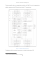
Figure 6–1 Hardware connections ...........................................................................................39 Figure 6–2 Motion system distance test ..................................................................................48 Figure 6–3 PWM waves before adjustment.............................................................................49 Figure 6–4 PWM waves after adjustment................................................................................50 Figure 6–5 Angle deviation with rotate movement .................................................................51 Figure 7–1 Future work ...........................................................................................................53 Figure C–1 Take measure function..........................................................................................60 Figure C–2 Function explore block diagram ...........................................................................61 Figure C–3 Auto escape function block diagram ....................................................................62 Figure C–4 Manual escape function ........................................................................................62 Figure C–5 Start exploring block diagram ..............................................................................63 Figure C–6 Select parameters function....................................................................................64 Figure C–7 Backlight function block diagram ........................................................................65 Figure C–8 Main menu block diagram ....................................................................................65 Figure C–9 Main loop block diagram......................................................................................66 4
Interactive Ultrasonic Guided System
ii. List of Tables
Table 1 Communication Speed Values of the I2C bus[3] .......................................................22 Table 2 Commands for the SRF08 [4].....................................................................................30 Table 3 Registers of the LCD display [5] ................................................................................35 Table 4 Commands for the LCD display [5] ...........................................................................36 Table 5 Matrix keypad values..................................................................................................37 Table 6 Registers used by the matrix keypad [5].....................................................................37 Table 7 Ultrasonic sensor test of measured distances..............................................................47 Table 8 Ultrasonic sensor test depending on the reflection surface ........................................47 Table 9 Deviation test ..............................................................................................................49 Table 10 Rotational movement test .........................................................................................52 5
Interactive Ultrasonic Guided System
iii. List of Abbreviations
ATMEL....................... Advanced Technology Memory and Logic
EEPROM .................... Electrically Erasable Programmable Read Only Memory
FIFO............................ First Input First Output
FTDI............................ Future Technology Devices International Ltd.
GNU............................ GNU is Not Unix
GCC ............................ GNU Compiler Collection
IC ................................ Integrated Circuit
IR ................................ Infrared
IIC or I2C .................... Inter –Integrated Circuit
LCD ............................ Liquid Crystal Display
MDI............................. Multiple Document Interface
MOSFET..................... Metal-Oxide Semiconductor Field-Effect Transistor
NiMh ........................... Nickel Metal Hydride
PCB............................. Printed Circuit Board
PFM ............................ Potential Field Method
PWM ........................... Pulsed Wave Modulation
SRAM ......................... Static Random Access Memory
ROM ........................... Read Only Memory
RP6.............................. Robot Project 6
SCL ............................. Serial Clock
SDA ............................ Serial Data
SRF ............................. Sonic Range Finder
TOF ............................. Time Of Flight
TWI ............................. Two-Wire Interface (it is a synonym of I2C)
UART.......................... Universal Asynchronous Receiver / Transmitter
USB............................. Universal Serial Bus
6
Interactive Ultrasonic Guided System
Contents
ABSTRACT..............................................................................................................................2
I. LIST OF FIGURES .............................................................................................................3
II. LIST OF TABLES..............................................................................................................5
III. LIST OF ABBREVIATIONS...........................................................................................6
1.
OVERALL DESIGN AND PRELIMINARY RESEARCH.......................................9
1.1 INTRODUCTION .................................................................................................................9
1.2 EVOLUTION OF THE PROJECT .............................................................................................9
2.
THE RP6 ROBOT........................................................................................................11
2.1 INTRODUCTION ...............................................................................................................11
2.2 MAIN CHARACTERISTICS .................................................................................................11
2.3 DETAILED FEATURES: .....................................................................................................13
2.3.1 Microcontroller.......................................................................................................13
2.3.2 Motion system .........................................................................................................15
2.3.3 Expansion system ....................................................................................................16
2.3.4 Power supply...........................................................................................................17
3.
THE WORKING ENVIRONMENT ..........................................................................18
3.1 SOFTWARE ......................................................................................................................18
3.1.1 GCC: GNU Compiler Collection............................................................................18
3.1.2 Programmer’s notepad ...........................................................................................19
3.1.3 RP6 Loader .............................................................................................................19
3.2 HARDWARE.....................................................................................................................21
3.2.1 The I2C Bus .............................................................................................................21
3.2.2 Serial Communication ............................................................................................24
4.
THE ULTRASONIC OBJECT AVOIDANCE SYSTEM........................................25
4.1 CURRENT RESEARCH ON OBJECT AVOIDANCE STRATEGIES ..............................................25
4.2 TIME OF FLIGHT ..............................................................................................................26
4.3 ULTRASONIC SENSOR CHOICE .........................................................................................28
4.4 THE SRF08 ULTRASONIC SENSOR ...................................................................................29
4.5 STRATEGY FOR THE OBJECT AVOIDANCE.........................................................................31
7
Interactive Ultrasonic Guided System
5.
THE INTERACTIVE DISPLAY SYSTEM ..............................................................34
5.1 LCD DISPLAY BASICS .....................................................................................................34
5.2 LCD DISPLAY ................................................................................................................35
5.3 MATRIX KEYPAD .............................................................................................................37
6.
RESULTS......................................................................................................................38
6.1 FINAL RESULT .................................................................................................................38
6.2 HARDWARE.....................................................................................................................39
6.3 SOFTWARE ......................................................................................................................40
6.3.1 Libraries..................................................................................................................41
6.3.2 LCD display and Matrix keypad functions .............................................................43
6.3.3 Ultrasonic system....................................................................................................44
6.3.4 Menu Functions ......................................................................................................46
6.3.5 Main program .........................................................................................................46
6.4 TEST RESULTS .................................................................................................................47
6.4.1 Measuring distances with the ultrasonic sensor.....................................................47
6.4.2 The motion system...................................................................................................48
6.4.3 The object avoidance system...................................................................................51
6.4.4 The LCD Display ....................................................................................................52
7.
FUTURE WORK .........................................................................................................53
8.
CONCLUSION.............................................................................................................54
A.
BIBLIOGRAPHY ........................................................................................................55
B.
STATEMENT OF WORK ..........................................................................................56
C.
SOFTWARE BLOCK DIAGRAMS ..........................................................................59
D.
SOFTWARE CODE.....................................................................................................67
E.
DATASHEETS .............................................................................................................79
F.
CD-ROM CONTENTS ................................................................................................80
8
Interactive Ultrasonic Guided System
1. Overall design and preliminary research
1.1 Introduction
The idea for this project came from my supervisor, Phil Tranter. From a list of possible topics
I chose the three most interesting for me.
The aim of the project is to develop an ultrasonic guided system, applied in a mobile robot in
order to avoid objects. Furthermore the project will provide a total remote control for the
robot, via a radio communication system of 434 MHz1.
All the systems must be included in a single PCB2 that fits in the robot bodywork. In addition
to this a remote control must be constructed.
1.2 Evolution of the project
The development of the project has had three main structural changes. At the beginning the
project consisted of the creation of the motion system for the platform, the design of the
ultrasonic avoidance object system and the implementation of the wireless remote control.
At the end of November my supervisor offered me a complete robot system called RP63
which improved my project possibilities because it has an integrated motion system that I can
use instead of designing my own system. The robot system also includes an I2C4 interface,
which was another topic of the proposal projects. The characteristics of the robot system are
explained in the Chapter 2. At this point the decision was taken to pursue a new direction of
the project and to start focusing more on software rather than hardware.
1
434 MHz band
PCB: Printed Circuit Board
3
RP6: Robot project 6
4 2
I C: Inter-integrated circuit
2
9
Interactive Ultrasonic Guided System
The next relevant change was at the beginning of February. The motion system and the
ultrasonic object avoiding system were properly working. The next step was to develop the
wireless remote controlled system. After studying the characteristics and regarding to the
time left until the end of the project, it was decided to leave the wireless remote control and
instead implement an LCD5 display and a keypad. This way the control will not be wireless
but the system will allow the user to change the different parameters of the object avoidance
system without the need of a computer. In addition, the LCD display also uses the I2C data
transmission system that will help to demonstrate its capability for managing several devices.
5
LCD: Liquid Crystal Display
10
Interactive Ultrasonic Guided System
2. The RP6 Robot
2.1 Introduction
The RP6 is a mobile robot system designed with the objective of introducing the user to the
world of robotics.
The product is a completely assembled system, which includes a microcontroller
ATMEGA32 and a large variety of sensors to interact with.
The robot is the perfect device for research and development of new features since one of its
main points is the great possibility of expansion. This means it is prepared for adding new
modules and allows the user to interact with them using a wide range of connections. With
the I2C bus is possible to add up to 127 devices and it also includes an expansion bus that
helps to connect external devices to the microcontroller.
2.2 Main characteristics
– Atmel ATMEGA32 8-Bit Microcontroller
– Flexible expansion system, based on the I2C-Bus
– Symmetrical mounting possibilities for expansion modules at front and rear
– USB PC Interface for program uploads from PC to microcontroller
– Powerful caterpillar drive unit in combination with a new gearing system for
minimising noise
– Two powerful 7.2V DC-Motors
– Two powerful MOSFET6 Motor-drivers (H-Bridges)
– Two high resolution encoders for speed- and motion-control
6
MOSFET: Metal Oxide Semiconductor Field-Effect Transistor
11
Interactive Ultrasonic Guided System
– Anti-collision-system (ACS) with an integrated IR7 receiver and two IR diodes
aligned to left and right
– Infrared Communication-system (IRCOMM)
– Two light sensors
– Two bumper sensors for collision detection
– 6 Status LED’s for sensor and program status displays
– Two free Analogue/Digital Converter (ADC) channels for external sensor systems
– Accurate 5V voltage regulation (maximum current supply of 1.5A)
– Replaceable 2.5A fuse
– Low standby current of less than 5mA (4mA typ. and ca. 17 up to 40mA in use)
– Power supply with 6 NiMh8 accumulator batteries.
– The main board provides 6 small expansion areas
7
8
IR: Infrared
NiMh: Nickel Metal Hydride
12
Interactive Ultrasonic Guided System
2.3 Detailed features:
This chapter describes the systems used in the project in detail.
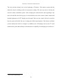
In Figure 2–1 shows a general overview of the robot systems and its main connections.
Figure 2–1 Overview schematic of the RP6 Robot System[1]
All the information in this chapter including schematics and datasheets is taken from [1] and
is included in the attached CD.
2.3.1 Microcontroller
The robot uses an Atmega32 microcontroller manufactured by Atmel [2].
It is an 8-bit microcontroller that has 32KB (32768 Bytes) Flash ROM memory and 2KB
(2048 Bytes) of RAM memory. It runs at a frequency of 8 MHz but it is capable of working
with a 16MHz clock. The system uses the 8MHz clock frequency for power saving reasons.
13
Interactive Ultrasonic Guided System
The microcontroller has two communication modules: the UART9 for serial communication
with the computer and the TWI-module used for the I2C expansion bus.
Figure 2–2 ATMEGA32 Block Diagram [2]
The datasheet with the complete characteristics is included in the attached CD.
9
UART: Universal Asynchronous Receiver / Transmitter
14
Interactive Ultrasonic Guided System
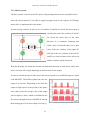
2.3.2 Motion system
The drive system is based on two DC motors with gearings that move the caterpillar wheels.
Since the microcontroller is not able to supply enough current to the engines, an H-bridge
motor drive is implemented in each motor.
It works closing switches in pairs of two. If switches S1 and S4 are closed, the motor turns in
one direction and if the switches S2 and S3
are closed the motor turns in the other
direction. It is extremely important that
when a pair is closed the other one is open
since if the two switches of the right (S3
and S4) or the two switches of the left (S1
and S2) are closed a short-circuit will occur
and the switches will be destroyed.
Figure 2–3 Mosfet H-bridge [1]
With the H-bridge we obtain the forward and backward direction of each motor, which also
allows it to turn left or right depending on the direction of each engine.
In order to control the speed of the motors the microcontroller uses its PWM output to control
each MOSFET. The PWM regulates the time the
output is in on-state. Depending on the time the
output is high respect to the period of the square
wave (duty cycle), the average value of the output
will be higher or lower, which is translated to the
DC motors through the power MOSFETs altering
their turning speed. The entire chapter is from [1].
15
Figure 2–4 PWM regulation [1]
Interactive Ultrasonic Guided System
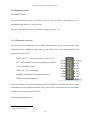
2.3.3 Expansion system
2.3.2.1 The I2C bus
The main expansion system of the robot is the I2C bus. It allows connecting up to 127
peripherals using only a two-wire interface.
This data communications bus is explained in depth in chapter 3.2.1
2.3.2.2 Expansion connectors
The robot has two expansion buses or XBUS that permit the power lines and some other
useful lines to be available in other places of the robot, such as the upper platform. The
pinout of the connector is:
-
SDA10 and SCL11 are the connections of the I2C bus.
-
INT1, INT2 and INT3 are the interrupt inputs of the µC.
-
+UB is the battery voltage.
-
VDD is the +5V power supply.
-
MRESET is the Master Reset Signal of the µC.
-
GND is the ground connection.
Figure 2–5 Expansion bus connector[1]
It also has another two expansion connectors called USRBUS1/2 that allow the user to make
connections between expansion modules. They just provide a connection between two boards
and they do not have any specific pinout.
Information obtained from [1]
10
11
SDA: Serial DAta line
SCL: Serial CLock line
16
Interactive Ultrasonic Guided System
2.3.4 Power supply
The power supply is obtained from six AA-type batteries. They provide a total voltage of
7.2V since each one of them has a 1.2V voltage. Due to the characteristic of rechargeable
batteries, if they are completely charged they can offer up to 9V. This is the cause of the
voltage variations in the signal +UB and the fluctuation depends on the charge level of the
batteries [1].
The robot system is equipped with a +5V regulator capable of supplying a maximum current
of 1.5A, but it is recommended not to use more than 800mA without using an additional heat
sink [1].
Some rechargeable batteries were studied1213 as well as chargers1415 but in the end some
batteries were borrowed from the lab. Their performance was not as expected, so finally
traditional alkaline power cells have been used for all the tests made for this project. Only
three packs of six batteries have been spent since the power consumption of the robot has not
been too high.
12
http://uk.farnell.com/ansmann/5035201/battery-rechargeable-nimh-aa/dp/1453781?Ntt=5035201
GP 2700mAh AA rechargeable batteries from Rapid electronics, now they are discontinued
14
http://www2.conrad-uk.com/goto.php?artikel=250125
15
http://www2.conrad-uk.com/goto.php?artikel=235703
13
17
Interactive Ultrasonic Guided System
3. The working environment
3.1 Software
The main objective of the project is to develop the necessary software to manage the robot.
This chapter explains all the software resources used for creating the robot software and the
subsequent process of programming the microcontroller.
All the programs are running under Windows XP Professional Version 2002 SP3
3.1.1 GCC: GNU Compiler Collection
The abbreviation GCC stands for GNU16 C Compiler. When it was created, it only entailed C
language but nowadays some other languages like Ada, Java or Fortran have been added to
the compiler.
The GNU Project17 is an operative system created by users and its main characteristic is that
it is completely free. It was launched in 1984 by Richard Stallman and today it is still being
developed. The GCC is the compiler created for this operative system.
The first version of the compiler was released on the 22 of March of 1987 and the most
recent is from the 25 of March of the current year18. The GCC compiler is distributed by Free
Software Foundation (FSF)19.
The complete libraries and archives of the compiler and the manuals can be found at
http://gcc.gnu.org/
16
GNU: GNU is Not Unix
more info in http://www.gnu.org/
18
http://gcc.gnu.org/releases.html
19
http://www.fsf.org/
17
18
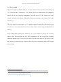
3.1.2 Programmer’s notepad
Programmer’s notepad is a free license code editor20. It supports C language with syntax
highlighting and it has a very useful tabbed MDI interface.
The main features of the program can be found in the developer website21.
The election of this text code editor was made because it is easy to use and at the same time it
is a powerful tool for software development. It is also the programme recommended by the
manufacturer of the robot.
Figure 3–1 About of Programmer's Notepad 2
The version of the program was 2.0.8 and it can be downloaded at:
http://www.pnotepad.org/download/
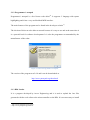
3.1.3 RP6 Loader
It is a program developed by Arexx Engineering and it is used to upload the .hex files
generated with the code editor to the microcontroller on the RP6. It is not necessary to install
20
21
http://www.pnotepad.org/licensing/
http://www.pnotepad.org/features/
Interactive Ultrasonic Guided System
it on the PC since it is written in Java. The program includes a terminal for monitoring the
data received from the robot. It has an option that allows the user check the memory status
and the value of each byte in the ROM.
Figure 3–2 RP6 Loader Screenshot
Figure 3–2 shows a screenshot of the RP6 Loader. The main parts of the program are:
1- Selection box for choosing the connection method to the robot. In this case the serial
connection detailed in chapter 3.2.2 appears.
2- Selection of the .hex file that is going to be sent to the robot.
3- Upload the selected file.
4- It is possible to start and stop the robot remotely.
5- This box shows the status of the robot. It includes the firmware version and the
updated battery voltage.
6- Tabs for selecting the terminal and the memory viewer (HexViewer).
20
Interactive Ultrasonic Guided System
3.2 Hardware
The implementation of this project does not require complex hardware since all the external
components needed are connected via the I2C bus. These components are the LCD display,
the keypad matrix and the ultrasonic sensor.
The robot is connected to the PC using a UART to USB22 interface, which is used for
programming the microcontroller and for receiving data from the robot.
All the physical connections are explained in detail in chapter 6.2
3.2.1 The I2C Bus
The I2C bus is a serial communication protocol designed by Philips at
the beginning of the 1980s.
Figure 3–3 I2C logo[3]
In the late seventies, the use of microprocessors in consumer electronics was increasing and
Philips started to think about one new solution to save some space in the PCBs. The reason
was that the data communications as well as the addresses used for interconnect integrated
circuits and microcontrollers occupied a large space of the board, since they used the parallel
communication system with a wide eight bits bus.
Philips researched for a low cost system that interconnects the data and address lines of the
microcontroller and the integrated circuits. This inter-IC bus was called IIC or I2C bus and it
started to be implemented in systems where size and cost were compulsory and the data
speed was not much important23.
22
23
USB: Universal Serial Bus
The historical information has been taken from http://www.lammertbies.nl/comm/info/I2C-bus.html
21
Interactive Ultrasonic Guided System
The I2C is a bidirectional serial communication system and the transmission can be done with
only two lines called SDA and SCL. SDA is used for transmitting the data bits and SCL is a
clock signal. The data sent through the SDA line include the address of the device required
and also the data requested.
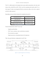
Depending on the specification adopted, the communication speed is:
Standard mode (Sm)
100 kbits per second
Fast mode (Fm)
400 kbits per second
Fast-mode plus (Fm+)
1 Mbit per second
High speed mode (Hs mode)
3.4 Mbit per second
Table 1 Communication Speed Values of the I2C bus[3]
The main characteristics of the I2C bus are [6]:
-
Simplicity and flexibility
-
TWI: Two wire interface, only two bus lines are required
-
No strict baud rate required
-
Simple master/slave relationships between all components
This is the typical hardware configuration for an I2C link:
Figure 3–4 Typical Configuration of an I2C link [6]
22
Interactive Ultrasonic Guided System
The elements of Figure 3–4 are:
– VCC: Supply voltage
– GND: Common ground
– SDA: Serial Data line
– SDL: Serial Clock line
– Rp: Pull-up resistance
– Rs: Serial Resistance
– Cp Wire capacitance
– Cc: Cross-channel capacitance
As shown in Figure 3–4 a pull-up resistor is connected from each line of the bus to the
positive rail. These resistors are necessary because when the bus is free both lines have to be
in high state.
23
Interactive Ultrasonic Guided System
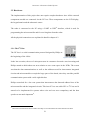
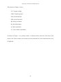
3.2.2 Serial Communication
The robot is connected to the PC via serial communication. It uses the FT232R24 chip from
the manufacturer FTDI25 that converts the UART signal to USB. The circuit includes a LED
that lights up when there is some activity.
The usual transfer speed between the computer and the robot is 500kBaud [1].
Figure 3–5 Board of the serial bus cable
24
25
datasheet is included in the CD. More info in http://www.ftdichip.com/Products/ICs/FT232R.htm
FTDI: Future Technology Devices International Ltd; http://www.ftdichip.com/
24
Interactive Ultrasonic Guided System
4. The Ultrasonic Object Avoidance System
There are many documented ideas and strategies for avoiding objects and walls26. Most of the
contemporary robots with that objective employ at least 3 different sensors in order to get
data from all sides of the robot27 and decide what to do. There are also projects that mount a
single ultrasonic sensor, but they include a servomotor for making the sensor work as a radar
system.
The budget of this project is restricted and installing more than one sensor or servomotors
would exceed the budget. The solution adopted is to use a fixed high precision ultrasonic
sensor with a wide beam pattern that takes measures in different positions in order to
calculate the right path to follow. This process is explained in more detail in the chapter 4.5.
4.1 Current research on object avoidance strategies
In the recent years one of the most popular techniques used in the object avoidance systems is
called potential field method or PFM28 that models the robot and its environment behaviour
using field arrows. It is a technique that was developed in the eighties but it is still in use
although there are some researches that expose its limitations.29
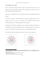
Another popular technique is working with fuzzy logic, which consists in considering more
than two possible states, introducing values between the logic 0 and 1. In this specific
example taken from the paper referenced in [8], the robot is using a ring of 24 ultrasonic
sensors for taking measures. The method is based on having a learning period in which the
26
For example, http://letsmakerobots.com/node/5305
http://ieeexplore.ieee.org/Xplore/login.jsp?url=http%3A%2F%2Fieeexplore.ieee.org%2Fiel5%2F10831%2F3
4146%2F01626586.pdf%3Farnumber%3D1626586&authDecision=-203
28
A complete tutorial written by Michael A. Goodrich is included in the CD
29
The paper containing that information is included in the attached CD. It is called “Potential field methods and
they inherent limitations for mobile robot navigation”, written by Y.Koren and J. Borestein.
27
25
Interactive Ultrasonic Guided System
robot analyses and stores various environmental factors (Figure 4–1) which allows the robot
to easily and quickly find its way to a predefined goal (Figure 4–2)
Figure 4–1 Learning phase[8]
Figure 4–2 Goal seeking[8]
There are some examples of papers based on both techniques included in the CD attached.
4.2 Time of flight
The values generated by the ultrasonic sensor are obtained using a technique called time of
flight (TOF).
This technique is based on the physics elementary formula which states that the distance
equals the speed multiplied by time (distance = speed x time).
In order to calculate the time, the system has an emitter that sends an energy wave. When this
wave hits a surface it is reflected and comes back to the receiver. The time the wave spends
in this process is measured.
26
Interactive Ultrasonic Guided System
The other factor in the equation is the speed. In this particular case it is the propagation speed
of the wave that the emitter sends. This value depends on the transmission medium, which in
this case is the air. After getting these values calculating the distance is easy.
TOF systems can have the following error sources:
-
Variations in the propagation speed: the speed of the acoustic waves is influenced by
changes in the temperature and in the humidity.
-
Uncertainties on calculating the travel time of the wave: can be caused by the
different reflectivity of the measured surfaces or by the signal attenuation with the
distance.
-
Inaccuracies in the circuit that measures the flying time: the circuitry must be faster
than the time the wave takes in coming back, so the nearer the target is the faster the
circuit has to be.
-
Surface interaction: if the angle of incidence of wave sent to the surface exceeds a
determined value, the reflection of the wave may not return to the position where the
receptor is.
All the information of this section has been obtained from [7].
27
Interactive Ultrasonic Guided System
4.3 Ultrasonic sensor choice
There is a wide range of ultrasonic distance sensors on the market, but there are only a few
which use the I2C communication protocol. After researching on the Internet, there were
three different possibilities to choose from.
The first one is the USR40x30 from www.mindsensors.com but it is discontinued and not sold
anymore31.
The other two options are both manufactured by the British company Devantech32. The
suitable models for the project are the SRF0233 and the SRF08. They have similar
characteristics but there are some slight differences between them.
According to the FAQs of the manufacturer,34 both sensors have similar beam patterns but
the SRF08 beam is wider than the SRF02 and this is a determinant factor since the robot uses
only one sensor and the wider the beam is the better it is to accomplish the objective.
This wide beam difference between the two sensors can be seen in the images below.
Figure 4–3 SRF02 Beam Pattern
Figure 4–4 SRF08 Beam Pattern
30
http://www.mindsensors.com/index.php?module=pagemaster&PAGE_user_op=view_page&PAGE_id=49
http://www.mindsensors.com/index.php?module=pagemaster&PAGE_user_op=view_page&PAGE_id=94&M
MN_position=20:20
32
http://www.robot-electronics.co.uk/acatalog/Contact.html
33
SRF: ultraSonic Range Finder
34
http://www.robot-electronics.co.uk/htm/sonar_faq.htm
31
28
Interactive Ultrasonic Guided System
Another difference is the measure range. The SRF0235 can measure from 15 cm to 6m and
the SRF08 is able to detect objects from 3 cm to 6 m. This means that the SRF02 is not able
to recognise objects that are too close which compromise the precision of the object
avoidance function.
In addition to these differences there are some reports of measurement errors using the
SRF02.36
According to the results of the comparison the ultrasonic sensor chosen was the SRF08.
Figure 4–5 SRF08 Front side
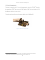
4.4 The SRF08 ultrasonic sensor
The main characteristics of this model are:
35
36
–
Voltage: 5v only required
–
Current: 15mA Typ. 3mA Standby.
–
Frequency: 40KHz
–
Range: 3cm - 6m.
–
Max Analogue Gain: Variable 94 to 1025 in 32 steps.
–
Connection: Standard I2C Bus.
–
Light Sensor: Front Facing light sensor.
The technical data is available at http://www.robot-electronics.co.uk/htm/srf02tech.htm
http://www.robot-electronics.co.uk/forum/viewtopic.php?f=2&t=3
29
Interactive Ultrasonic Guided System
–
Echo: Multiple echoes.
–
Units: Range reported in microseconds, millimeters or inches.
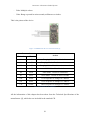
This is the pinout of the device:
Figure 4–6 SRF08 back side view and connections [4]
Commands
Action
Decimal
Hex
80
0x50
Ranging Mode - Result in inches
81
0x51
Ranging Mode - Result in centimetres
82
0x52
Ranging Mode - Result in micro-seconds
83
0x53
ANN Mode - Result in inches
84
0x54
ANN Mode - Result in centimetres
85
0x55
ANN Mode - Result in micro-seconds
160
0xA0
1st in sequence to change I2C address
165
0xA5
3rd in sequence to change I2C address
170
0xAA
2nd in sequence to change I2C address
Table 2 Commands for the SRF08 [4]
All the information of this chapter has been taken from the Technical Specifications of the
manufacturer [4], which also are included in the attached CD.
30
Interactive Ultrasonic Guided System
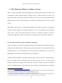
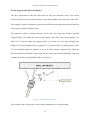
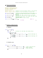
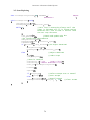
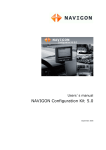
4.5 Strategy for the object avoidance
The basic requirement is that the robot must use only one ultrasonic sensor. The chosen
position for the sensor in the robot structure is just in the middle of the front side of the robot.
The strategy is based on making two measures in different points and afterwards calculate the
escape angle using the obtained values.
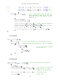
The ultrasonic sensor is taking measures all the time and when the distance obtained
(segment OB) is less than the selected stop distance, the robot stops (point number 1 of
Figure 4–7). Once the robot has stopped (point 2) it rotates 45º to its right and takes the
distance to the wall (Right measure, segment OC). It comes back to its initial position, turns
45º left and takes again the distance to the wall (Left measure, segment OA). Then the
microcontroller calculates the escape angle and the robot rotates the obtained angle value and
continues forward in a path parallel to the wall (point 3).
Figure 4–7 Objects Avoidance Strategy
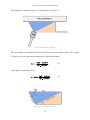
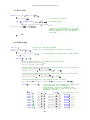
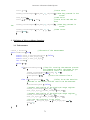
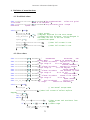
The calculus of the escape angle is based on the trigonometry of a right triangle.
31
Interactive Ultrasonic Guided System
The triangles are shown in Figure 4–8 and the angles in Figure 4–7
Figure 4–8 Escape angle calculation
The first triangle is formed by the wall, the left measure and the right measure. The α angle
of Figure 4–9 can be calculated by applying the following formula:
[1]
so the angle is obtained from [1]:
[2]
Figure 4–9 Escape angle calculation 2
32
Interactive Ultrasonic Guided System
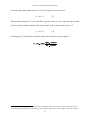
From the right angle and the value of α in [2], the angle β can be incurred:
β = 90º - α
[3]
With the data obtained in [3] it is possible to get the value of ϕ (the angle the robot should
rotate in order to follow a parallel path respect to the wall) as shown in the Figure 4–7:
ϕ = 45 + β
[4]
Combining [2], [3] and [4] the complete equation that obtain the escape angle is37:
37
Note that if the robot approximates to the wall in a different angle that the shown in the example, the values
for calculating the function arctan can change. The numerator always has to be the longer one of both measures.
33
Interactive Ultrasonic Guided System
5. The Interactive Display System
5.1 LCD display basics
The purpose of a display is to convert electric signals into visual information. A display is
composed by small areas called pixels. The different pixels of the display are switched on
and off and all of them together create the desired image to show. There are two basic types
of displays depending on the shape of their pixels:” seven-segment displays” and “dot-matrix
displays” [9]. Their structure is shown in the next figure.
Figure 5–1 Seven-segment and dot matrix display [9]
Depending on the way the pixels are activated it is possible to differentiate between active
and passive matrix. The active matrix displays have one semiconductor device in each pixel
for turning it on and off. Normally it is a transistor that acts as a switch. In the passive matrix
display the columns and the rows of the matrix are the electrodes [9]. Both methods are
shown in the next figure:
Figure 5–2 Passive and active matrix displays [9]
34
Interactive Ultrasonic Guided System
5.2 LCD Display
It is a passive dot matrix display with twenty characters per row and four rows (20 x 4) so it
can display eighty characters at the same time. Each character is composed of a 5 by 7
matrix. It requires a power supply of 5 V. It includes a driver circuit that gives the possibility
of controlling it via I2C or via serial mode.
The module has a mode selection jumper for choosing between the I2C and the serial mode.
This choice must be done before switching on the device since the driver check that jumper
in the starting routine. The I2C mode is selected when the jumper is open.
In this mode, the data communications system is faster than the LCD can accept data so it is
included a FIFO buffer of 64 bytes that stores the data the LCD cannot show until it is
displayed.
The address of the display when it is connected to the I2C bus is 0xC6. The LCD has four
registers, detailed in the next table:
Register
Read
Write
0
Number of free bits in FIFO buffer
Command Register
1
Keypad state low byte
Not available
2
Keypad state High byte
Not available
3
Version
Not available
Table 3 Registers of the LCD display [5]
The register number 0 is the only one that has a double purpose since it can be read or
written. In written mode this register takes the commands for the LCD display. When it is
read it shows the number of free bits that rest in the FIFO buffer. Register one and two show
the status of the matrix keypad and register three shows the current version of the LCD
software.
35
Interactive Ultrasonic Guided System
These are the commands that can be set to the command register:
Decimal
Command
Description
0
Null (ignored)
Ignored as a no operation
1
Cursor Home
Sets the cursor to the home position (top left)
2
Set cursor (1-80)
Cursor to a position specified by the next byte, where 1 is the
top left and 80 is the bottom right
3
Set cursor (line, column)
Sets cursor using two bytes, where first byte is the line and
the second byte is the column
4
Hide cursor
Stops the position cursor from appearing on the display
5
Show underline cursor
Changes the cursor to the underline type
6
Show blinking cursor
Changes the cursor to the blinking type
8
Backspace
Deletes the preceding character from the current position on
the display
9
Horizontal tab (by tab
set)
Moves the current position across by the tab space set by
command18 (default tab space 4)
10
Smart line feed
Moves the cursor down one line to the position beneath in the
same column
11
Vertical tab
Moves the cursor up one line to the position above in the
same column
12
Clear screen
Clears the screen and sets cursor to the home position
13
Carriage Return
Moves the cursor to the start of the next line
17
Clear Column
Clears the contents of the current column and moves cursor
right by one column
18
Tab set
Sets the required tab size, the following byte can be a size of
between 1 and 10
19
Backlight on
Turns the backlight of the LCD03 on
20
Backlight off (default)
Turns the backlight of the LCD03 off
27
Custom char generator
Allows 8 custom chars to be built.
32-255
ASCII chars
Writes ASCII chars straight to the display
Table 4 Commands for the LCD display [5]
The information of this chapter has been obtained from the manufacturer’s Technical
Documentation [5]. The complete technical documentation including detailed connections
and measures is included in the CD-ROM.
36
Interactive Ultrasonic Guided System
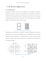
5.3 Matrix keypad
It is a four rows and three columns matrix keypad and in each intersection it has a switch
associated to a push-button. The keypad is connected to the LCD module using a seven-line
bus. Three of these lines are input signals introduced in the keypad and the other four are the
outputs of each row. The module sends a signal to the first column and checks if any of the
COL 1
COL 2
COL 3
switches is on. If this happens, a signal is sent in the corresponding output.
ROW 1
1
2
3
ROW 2
4
5
6
ROW 3
7
8
9
ROW 4
*
0
#
Table 5 Matrix keypad values
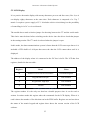
The module is constantly scanning the keypad to detect changes in the keys and it reflects the
changes in two registers. These registers are located in the addresses one and two of the LCD
module. In the next table both registers are represented. They indicate the key that has been
pressed sorted by its position in the keypad (Row/Column).
High byte
0
0
0
0
0
0
0
0
Low byte
4/3 4/2 4/1 3/3 3/2 3/1 2/3 2/2 2/1 1/3 1/2 1/1
#
0
*
9
8
7
6
5
4
3
2
Table 6 Registers used by the matrix keypad [5]
When one key is pressed the corresponding bit in the register will be in high state.
This information is included in the Technical Documentation [5].
37
1
Interactive Ultrasonic Guided System
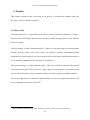
6. Results
This chapter explains all the work done in the project. It includes the hardware built, the
developed software and the tests done.
6.1 Final results
The result obtained is a system that avoids objects with two different strategies. A menu is
showed in the LCD display and the user can choose which strategy prefers to use with the
help of a keypad.
The first strategy is called “Automatic mode”. In this case, the robot stops at a predetermined
distance from the object. After that it takes two distance measures and mathematically
calculates the required angle to get away from the object following a parallel path respect to
it. The detailed explanation of the operation is in chapter 4.5.
The second strategy is called “Manual mode”. The user is asked to introduce the desired
values with the keypad. These values are: explore degrees, escape degrees, stop distance and
robot speed. After that the object avoidance routine will start using the specified parameters.
The robot is supposed to be automatic and autonomous so once the program is started it will
not stop until the reset button is pressed38.
38
The reset button of the robot is next to the serial bus connector, it is the same as the start button.
38
Interactive Ultrasonic Guided System
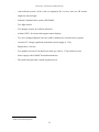
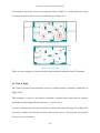
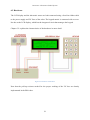
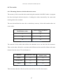
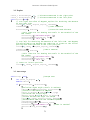
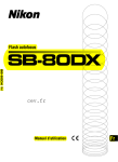
6.2 Hardware
The LCD display and the ultrasonic sensor are both connected using a four-line ribbon cable
to the power supply and I2C lines of the robot. The keypad matrix is connected with a sevenline bus to the LCD display, which has the integrated circuit that manages the keypad.
Chapter 3.2 explains the characteristics of the hardware in more detail.
Figure 6–1 Hardware connections
Note that the pull-up resistors needed for the proper working of the I2C bus are already
implemented in the RP6 robot.
39
Interactive Ultrasonic Guided System
6.3 Software
The robot microcontroller is programmed in C language. The developed program has been
divided in several parts depending on the system the code is referring to. This separation
helps to test specific sections of the code without compromising the rest of the program. It is
also based on a large number of functions since this way the code is neat and more efficient.
There are three groups of function declarations. The first two have the purpose of controlling
the hardware system: one is composed by the functions that control the ultrasonic sensor and
the other one is in charge of the LCD display and the keyboard matrix. The third group is
responsible for the software of the functions that appear in the main menu.
After that the main program is declared which includes an infinite loop with the main menu
included.
Therefore the basic structure of the software is the following:
-
Include libraries
-
Variables and constants declaration
-
Declaration of LCD display and keypad functions
-
Declaration of ultrasonic sensing functions
-
Declaration of main menu functions
-
Main loop
In the following chapters the purpose of each function will be explained. Appendix C
includes some block diagrams designed for better comprehension of the code, which is
included in appendix D. Their location is referenced next to the name of each function.
40
Interactive Ultrasonic Guided System
6.3.1 Libraries
The program needs to have a number of libraries. Most of them are included in the GCC
compiler but there is a group of libraries that have been specifically developed by Arexx
Engineering for controlling this robot.
These libraries include some necessary functions for the proper operation of the RP6. Below
is a short explanation about each library and the functions taken from them.
6.3.1.1 RP6RobotBaseLib.h
This library includes the basic operations of the robot. The following functions are used:
-
mSleep(x): this routine introduces a delay of x milliseconds in the code. It blocks the
normal flow of the program until the delay time is finished.
-
startStopwatch(): this function initializes a counter that runs regardless of the normal
program flow.
-
setStopwatch(t):sets the counter to a specific t initial value.
-
getStopwatch() take the instant value of the counter.
-
rotate(uint8_t desired_speed, uint8_t dir, uint16_t angle, uint8_t blocking): makes the
robot turn with the selected parameters: rotating speed, direction of turning, rotating
angle and an option for blocking the program flow while the robot is rotating.
-
changeDirection(uint8_t dir): sets the turning direction of each motor to move the
robot in the required direction. The possibilities are FWD, BWD, LEFT or RIGHT.
-
moveAtSpeed(uint8_t desired_speed_left, uint8_t desired_speed_right): this routine
sets the speed value for each motor.
-
task_RP6System: this function is in charge of updating all the systems of the robot. It
checks and updates the changes in the motion system and other systems not relevant
for the project like the analogue to digital converter or the bumpers status.
41
Interactive Ultrasonic Guided System
-
initRobotBase: this function initializes all the systems of the robot including the
configuration of the sensors and the microcontroller.
-
stop():if the robot is moving a distance or rotating, this function stops it immediately.
6.3.1.2 RP6uart.h
-
writeStringP: writes a string from the program memory to the UART.
-
writeInteger(number, base): writes a number to the UART and it specifies the base
between hexadecimal, decimal or binary.
6.3.1.3 RP6I2CmasterTWI.h
This library has the purpose of controlling the I2C communication bus. The functions taken
from it are:
-
I2CTWI_initMaster(100): Sets the operation frequency of the bus(the frequency in
kHz of the SCL line)
-
I2CTWI_transmitByte (LCD_ADR, 1): sends one byte to the specified address.
-
I2CTWI_transmit2Bytes (LCD_ADR, 0, 19):sends two bytes to the specified address.
-
I2CTWI_readByte(LCD_ADR):reads one byte from the address
-
task_I2CTWI: updates the status of the bus.
6.3.1.4 Pgmspace.h
This library is necessary for managing the memory of the microcontroller. The ATMEGA32
has 2KB of RAM memory and 32KB of ROM (or program memory).
The LCD display has 80 characters, and each one of them needs 1 byte. That means that
every message shown on the screen (if the message fills all the characters) occupies 80 bytes.
The Ram memory is limited to 2048 bytes, which is not enough for all the messages and the
42
Interactive Ultrasonic Guided System
rest of variables that need to be stored in this memory. Therefore the message arrays must be
saved in the program memory.
To ensure that the variables are stored in the correct place the macro “PROGMEM”39 40 must
be added after the declaration of a variable. After that, every time the variable needs to be
used it has to be called by using its address, not its variable name. To get the address of the
variable the symbol “&” has to be added before it.
6.3.1.5 math.h
There is only one function taken from this library. It is called atan2(x,y) and it calculates the
arctangent of an angle between the x axis plane and the point located in the coordinates (x,y).
6.3.2 LCD display and Matrix keypad functions
6.3.2.1 Blinking (code in page 68)
The objective of this function is making the backlight of the LCD blink when an object is
detected.
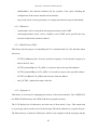
6.3.2.2 Initialize cursor (code in page 68)
This function cleans the screen and set the cursor in the first position of the first line. In
addition it hides the cursor.
6.3.2.3 Write LCD (code in page 69)
The LCD display has 80 characters and the purpose of this function is sending them to fill the
screen.
39
For more information read GCC and the PROGMEM Attribute by Dean Camera, included in the CD-ROM.
40
This information is also in the official AVR libraries website:
http://www.nongnu.org/avr-libc/user-manual/pgmspace.html
http://www.nongnu.org/avr-libc/user-manual/group__avr__pgmspace.html
43
Interactive Ultrasonic Guided System
First of all, it uses the function init_cursor() for initializing the cursor and after that it sends
the characters one by one until the screen is complete.
Note that the characters are read from the program memory and the function pgm_read_byte
is used for retrieving the data.
6.3.2.4 Read keypad (code in page 69)
This function is in charge of reading the keys pulsed by the user. It recognizes what key is
pressed and also includes a string with its the name, which is useful for showing the key
value on the screen.
It is important to detect only one pulsation each time the key is pressed so the function waits
until the key is released for returning the result required.
6.3.2.5 Wait hash (code in page 70)
A signal from the keypad is needed to move to the next screen and the key “#” has been
chosen. This function waits in a loop until the mentioned character is read.
6.3.2.6 Read value (code in page 70)
This function reads the values introduced by the user in the manual mode and it also shows
the characters read in the screen.
6.3.3 Ultrasonic system
This group contains all the functions relating to the object avoidance system. They are in
charge of getting the data from the environment using the SRF08 sensor from chapter 4.3
The first function has the objective of obtaining the distance measures and the rest of them
are related to the object avoidance system.
44
Interactive Ultrasonic Guided System
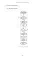
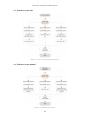
6.3.3.1 Function take measure (code in page 71 and block diagram in page 60)
This function is one of the most utilised since it gets the distance measures from the
ultrasonic sensor. The sensor requires at least 70ms to have a correct measure because it has
to wait until the ultrasonic wave returns to it.
6.3.3.2 Function explore (code in page 72 and block diagram in page 61)
This function is in charge of obtaining the measure of the distance in two different points. It
makes the robot rotate 45 degrees to each side from the stop position in order to take the
measures. These measures will be used for deciding the direction to escape.
The explanation of the purpose of this function is detailed in chapter 4.5
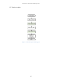
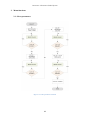
6.3.3.3 Function automatic escape (code in page 72 and block diagram in page 62)
This function calculates the value of the angle that the robot should turn in order to avoid the
object. It is based in some mathematical calculations, one of them is the function atan2
included in the math.h library.
The escape angle is calculated using the steps explained in chapter 4.5
6.3.3.4 Function manual escape (code in page 73 and block diagram in page 62)
In this function the robot avoids the object using an angle defined by the user.
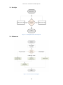
6.3.3.5 Start exploring function (code in page 74 and block diagram in page 63)
This is the function that is active when the robot is moving and it does not have any obstacle
in front of it. It is always taking measurements and when the space between the robot and the
object is less than the selected (defined in the variable stop_distance) it makes the robot stop
and execute the functions previously defined called “explore” and “escape”.
45
Interactive Ultrasonic Guided System
6.3.4 Menu Functions
6.3.4.1 Menu (code in page 77 and block diagram in page 65)
This function shows a screen with the three options available to choose. Then it reads the key
introduced by the user and calls the necessary functions to complete the objective of the
selected option.
6.3.4.2 Predefined values (code in page 75)
The variables for the object avoidance system are assigned to predefined values. The values
are detailed in the code. It also selects the automatic mode.
6.3.4.3 Select parameters (code in page 75 and block diagram in page64)
This function requires the user to enter the needed parameters for the manual mode. It asks
for each value and then checks the value is within the acceptable range. It sets the escape
mode as manual mode.
6.3.4.4 Backlight (code in page 77 and block diagram in page 65)
This menu option allows the user to switch on and switch off the LCD backlight.
6.3.5 Main program
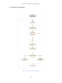
6.3.5.1 Main program(code in page78 and block diagram in page 65)
The main function initialises and configures the following systems: RP6 robot, I2C
communications bus, ultrasonic range finder and the LCD display. After that it shows the
welcome screens and at the end it enters in an infinite loop. Each time the program goes
across this loop the RP6 and the I2C bus are checked and updated and the function menu is
executed.
46
Interactive Ultrasonic Guided System
6.4 Test results
6.4.1 Measuring distances with the ultrasonic sensor.
The accuracy of the sensor has been tested using the terminal of the RP6 Loader. A program
has been developed with the objective of reading the values measured by the sensor and
showing them in the terminal.
The tests showed that the sensor has a satisfactory accuracy. In the table number there are
some results:
Real Distance (cms)
Sensor measured distance
(cms)
3
4
10
10
50
50
Table 7 Ultrasonic sensor test of measured distances
The material of the surface that reflects the ultrasonic wave can also alter the measures.
These are the data collected in a test done with different surfaces and all of them at the same
distance from the sensor. The real distance is
Material
Real distance (cms)
Sensor measured
distance (cms)
Plastic
15
15
Varnish wood
15
15
Fabric
15
15
Table 8 Ultrasonic sensor test depending on the reflection surface
This test shows that the reflection surface material does not affect the measure.
47
Interactive Ultrasonic Guided System
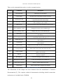
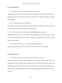
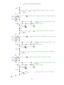
6.4.2 The motion system
The accuracy of the robot’s movements is not very high. There are two different motors, one
for each caterpillar and they cannot be calibrated separately. Both encoders are using the
same conversion factor but due to mechanical issues they are not providing the same
movement to each one of the caterpillar wheels. The function moveAtSpeed (speedLeft,
speedRight) is used to perform the tests. It requires two input parameters and each one of
them represent the speed of each motor. By observing the robot moving across a theoretically
straight line it can be deduced that the left motor runs slower that the right one, which ends in
a deviation movement towards the left. The objective of the tests is to get the values that
compensate the difference between the two motors by correcting the left one.
Figure 6–2 Motion system distance test
The correction has been introduced as follows: moveAtSpeed (speedLeft + balance value,
speedRight). The chart below shows the deviation of the robot respect a straight line.
The surface material has not too much influence in this test since both wheels have the same
grip and the conditions for each motor are the same.
The tests were done using various correction values in the left motor and with different speed
values.
48
Interactive Ultrasonic Guided System
Speed
60
90
120
Correction in the left
motor
0
Deviation (cms)
6
+6
4
+12
0
0
10
+6
5
+12
1
0
18
+6
10
+12
1
Table 9 Deviation test
Considering the results of the test, the left motor has been software-adjusted using the
exemplary value of +12 every time the function moveAtSpeed is called. With this value the
robot has an acceptable straight movement when it is required.
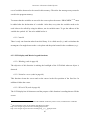
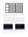
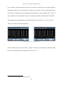
However, there is another method that can help to improve the behaviour of the motors. In
both motor drivers there are two potentiometers that control the duty cycle of the PWM
wave. The RP6 Loader can show the waveform of the PWM signal if the self-test program is
running. If is not properly calibrated you have the possibility of adjusting the PWM duty
cycle. These are the waves before adjusting the PWM:
Figure 6–3 PWM waves before adjustment
As shown in the Figure 6-3 the square wave does not have a 50:50 duty cycle and it needs
calibration.
49
Interactive Ultrasonic Guided System
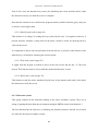
It is a delicate operation that must be done in a dark environment since the direct light can
damage the optical sensors that read the encoders of the gearbox. The only information about
this process is obtained from the English-speaking forum of Arexx Engineering41, but it is
only available in a pdf-document written in German[10], which is included in the CD-ROM.
The manufacturer documentation says that an adjustment of 60:40 or vice versa is correct.
These are the waves after the adjustment:
Figure 6–4 PWM waves after adjustment
After executing this process the robot is capable of moving in a straight line without needing
the software compensation calculated in the previous test.
41
http://www.arexx.com/forum/viewtopic.php?t=580
50
Interactive Ultrasonic Guided System
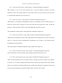
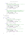
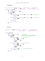
6.4.3 The object avoidance system
As mentioned in the previous section, the motion system has a remarkable influence on the
object avoidance function. This task needs the robot to turn 45º degrees to the right and then
come back to its initial position and turn 45º left. The difference between the two motors is
again decisive for achieving the appropriate angles. The executed tests show that the rotate
function is not accurate and the robot does not stop at the proper angles. The calculation of
the escape angle is not correct because of this.
Figure 6–5 Angle deviation with rotate movement
As seen in Figure 6–5, the robot’s initial position is the coloured in grey. After the rotational
movement the robot should be in the green position, but due to the mentioned inaccuracies
the robot may rotate more degrees until the red position. This deviation will cause a wrong
escape angle calculation.
51
Interactive Ultrasonic Guided System
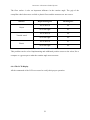
The floor surface is also an important influence in the rotation angle. The grip of the
caterpillar wheels decreases on tiled or plastic floors and the measures are not correct.
Surface
Requested degrees
Real degrees
45º to the left
48
45º to the right
42
45º to the left
44
45º to the right
40
45º to the left
43
45º to the right
40
Carpet
Varnish wood
Plastic
Table 10 Rotational movement test
This problem can be solved implementing and additional position sensor to the robot, like a
compass or a gyroscope to make the rotation angle more accurate.
6.4.4 The LCD Display
All the commands of the LCD were tested to verify their proper operation.
52
Interactive Ultrasonic Guided System
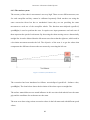
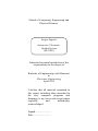
7. Future work
The most important improvement can be the implementation of a compass or gyroscope in
order to have a proper feedback about the real position of the robot. With that information the
rotate movement would have a high accuracy, which means that the obtained measures for
the calculation of the escape angle will be really precise. That way the escape angle will be
perfectly know. The gyroscope will also check that the robot has rotate the exactly escape
angle.
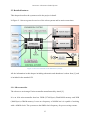
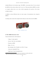
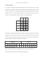
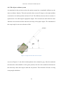
Another form of expansion can be to add more ultrasonic sensors since the I2C bus has the
capability of managing up to 127 devices. With three sensors the same algorithm for avoiding
objects can be used. The two new sensors can be installed in the robot in a position of 45
degrees respect to the middle sensor (Figure 7–1), so the rotate movement for taking
measures is not necessary anymore. The measures are done faster and they are more reliable
since the possible rotate errors are eliminated.
Figure 7–1 Future work
53
Interactive Ultrasonic Guided System
8. Conclusion
The work of the whole year has paid off and the project has accomplished its main objective
of avoiding objects using an ultrasonic sensor.
The software developed meets the requirements of control an ultrasonic sensor and manage
the results obtained. The algorithm designed for avoiding objects is mathematically justified
and is really simple to implement.
However, there are some problems that do not allow the system to work with a high
accuracy. Regarding to the motion system, the motors cannot be calibrated with a high
precision. This is problematic because the robot is not able to move forward in a completely
straight line. That is also the cause of the mistakes in calculating the new robot path since the
rotation movements are not accurate and the measures are not taken in the correct place.
The LCD display system works well and does what it is required to do. The amount of
memory needed to fill the entire display is considerable high and at the beginning was a
problem since there are several different screens. The amount of RAM is limited and store
the char arrays in the ROM is imperative. In order to reach this objective and save the
variables in the program memory, it requires the use of the PROGMEM attribute, the
operation of which was difficult to understand.
54
Interactive Ultrasonic Guided System
A. Bibliography
[1]
Arexx Engineering. (2007). RP6 Robot System Manual. Zwolle, The Netherlands:
Arexx Engineering.
[2]
Atmel Corporation. (March 2005). Datasheet: 8-bit AVR Microcontroller with
32K Bytes In-System Programmable Flash. San Jose, CA, USA.
[3]
NXP. (2007, Junio 19). I2C-bus specification and user manual.
[4]
Devantech LTD. SRF08 Ultrasonic range finder technical specification
[5]
Devantech LTD. LCD03 I2C Display module technical documentation
[6]
telos EDV Systementwicklung GmbH. (1997). i2c bus. Retrieved January 15,
2011 from i2c bus: http://www.i2c-bus.org/
[7]
Everett, H. R. (1995). Sensors for mobile robots. Natick, MA, USA: A K Peters.
[8]
H. Boubertakha, M. T.-Y. (2010). A new mobile robot navigation method using
fuzzy logic and a modified Q-learning algorithm. Journal of Intelligent & Fuzzy
Systems 21 , 113-119.
[9]
Fisch, M. R. (2004). Liquid crystals, laptops and life. World Scientific Publishing
Company, Incorporated .
[10]
Arexx Engineering. (2007). Drehgeber richtig einstellen. Zwolle, The
Netherlands: Arexx Engineering. (The translated title is “Set encoders correctly”)
55
Interactive Ultrasonic Guided System
B. Statement of Work
EL3990 Statement of Work
Interactive Ultrasonic Guided System
B.Eng. (Hons.) Electronic Engineering
Issue 1, 29 October 2010
S. Zapatel
1- Aim
The aim of the project is to develop an ultrasonic guided system, applied in a mobile robot in
order to avoid objects. Furthermore a LCD display with a matrix keypad will be added to
monitor the activity of the robot and interact with the robot. All of these peripherals will be
connected using the I2C data communication bus.
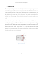
2- Background
There are many existing robot applications which require the robot to be able to avoid
obstacles without human supervision. A very recommendable way of providing that
characteristic is using ultrasonic sensors to detect obstacles (Bishop, 2008). In order to do so,
these sensors must be supported by a microcontroller, which will determine the new path of
the robot, depending on the programmed strategy.
A prebuilt robot will be used to achieve this objective. The included microcontroller will be
programmed with an algorithm that takes data from an ultrasonic sensor and after analyzing
them allows the robot to decide which way it should move to.
At the same time it is required to monitor and control the system results without the use of a
computer, in order to let the robot have the mobility necessary. To solve this problem, a LCD
display will connect the robot with the environment and a matrix keypad will contribute to
interact with the robot.
3- Activities
3.1- Work breakdown structure
1.
Research for general information
1.1.
Choosing main topic of the project
1.2.
Choosing specifications
2.
Progress report preparation
3.
RP6 Robot System
3.1.
Literature review and researching
3.2.
Research about its motion system
3.3.
Programming robot microcontroller
3.4.
Test of motion system
4.
Ultrasonic guided system
4.1.
Literature review and researching
56
Interactive Ultrasonic Guided System
4.2.
Choosing kind and number of sensors and object avoiding strategy.
4.3.
Designing electronic circuit
4.4.
Programming robot microcontroller
4.5.
Test of ultrasonic guided system
5.
LCD display system.
5.1.
Research about LCD displays
5.2.
Choose LCD display
5.3.
Programming robot microcontroller
5.4.
Test the LCD display
6.
Overall general test
7.
Building prototype
7.1.
Add sensor and display to the robot
7.2.
Check the connections
8.
Final test of the prototype
9.
Final report preparation
10.
Preparation viva/poster presentation.
3.2- Task descriptions
First, a research on the Internet will be done to choose the main topic of the project and its
specifications (WBS 1.1, WBS 1.2).
The first one of the reports will be a Progress Report that includes the aim of the project, the
initial steps done for its development and the planning for finishing the project successfully
(WBS 2).
Then the RP6 robot system will be studied (WBS 3), beginning with a research on its
instruction manual and datasheets (WBS 3.1). The research will focus in its motion system
(WBS 3.2) and the code necessary for achieve the proper movements will be designed (WBS
3.3). A test of the robot and the programming will check the proper working of the motion
system (WBS 3.4).
After that a research on the Internet will be done (WBS 4.1) in order to find the best solution
regarding the ultrasonic sensors, i.e. which kind of sensor and which strategy is going to be
used in the project (WBS 4.2). The electronic circuit for the ultrasonic sensors will be
designed (WBS 4.3) and the programming will be done (WBS 4.4). A test will be done to
check the ultrasonic sensors system (WBS 4.5).
The next step will be designing the LCD display system (WBS 5). A research on that kind of
displays will be done (WBS 5.1) and the necessary LCD will be chosen (WBS 5.2). The
robot microcontroller will be programmed for showing the appropriate messages in the
display (WBS 5.3). The LCD display system will be tested (WBS 5.4) exploring all the
possibilities of the display.
Then a general test of the entire system will be done (WBS 6). Once checked that all the
systems are working properly, all the external elements will be added to the robot (WBS 7.1),
and all the connections will be checked (WBS 7.2).
The final test of the complete prototype will be done (WBS 8).
The final report will be written which includes all the work done and the final conclusions
(WBS 9).
Finally, the viva voice and poster presentation will be prepared (WBS 10).
57
Interactive Ultrasonic Guided System
3.3- Programme
A Gantt chart is attached.
4- Dependencies
Electronics Laboratories of Computer & Technology Building will be needed for doing all
the necessary tests.
5- Risk management
1. Non-availability of Pc, causing delay and loss of project data. This risk will be managed
by saving all the work in UCLan servers, because they are more safety.
2. Loss of project documents. A back up of the hard drive containing all the data will be
done everyday automatically to an external hard drive, preventing the possible failure of
the computer hard drive.
3. Delays in procurement of components leading to failure to complete on time. This risk
will be managed by ordering all components at least 15 working days before they are
needed.
6- Deliverables
Item
Due date
Progress Report
29 Oct 2010
Final report (2 copies)
15 Apr 2011
7- References
Bishop, R. H. (2008). Mechatronics systems, sensors, and actuators:fundamentals and
modelling. Boca Raton: CRC Press.
58
Interactive Ultrasonic Guided System
C. Software block diagrams
In this appendix are included the block diagrams considered necessary for the understanding
of some functions. The green boxes are references to a specific function.
1.
2.
3.
ULTRASONIC SYSTEM FUNCTIONS ...................................................................60
1.1.
TAKE MEASURE FUNCTION ........................................................................................60
1.2.
FUNCTION EXPLORE ..................................................................................................61
1.3.
FUNCTION ESCAPE AUTO ...........................................................................................62
1.4.
FUNCTION ESCAPE MANUAL ......................................................................................62
1.5.
FUNCTION START EXPLORING ...................................................................................63
MENU FUNCTIONS ...................................................................................................64
2.1.
SELECT PARAMETERS ................................................................................................64
2.2.
BACKLIGHT ...............................................................................................................65
2.3.
MAIN MENU ..............................................................................................................65
MAIN PROGRAM.......................................................................................................66
59
Interactive Ultrasonic Guided System
1. Ultrasonic system functions
1.1. Take measure function
Figure C–1 Take measure function
60
Interactive Ultrasonic Guided System
1.2. Function explore
Figure C–2 Function explore block diagram
61
Interactive Ultrasonic Guided System
1.3. Function escape auto
Figure C–3 Auto escape function block diagram
1.4. Function escape manual
Figure C–4 Manual escape function
62
Interactive Ultrasonic Guided System
1.5. Function start exploring
Figure C–5 Start exploring block diagram
63
Interactive Ultrasonic Guided System
2. Menu functions
2.1. Select parameters
Figure C–6 Select parameters function
64
Interactive Ultrasonic Guided System
2.2. Backlight
Figure C–7 Backlight function block diagram
2.3. Main menu
Figure C–8 Main menu block diagram
65
Interactive Ultrasonic Guided System
3. Main program
Figure C–9 Main loop block diagram
66
Interactive Ultrasonic Guided System
D. Software code
1.
LIBRARIES AND DEFINITIONS.............................................................................68
2.
DEFINITION OF DISPLAY FUNCTIONS ..............................................................68
3.
4.
5.
2.1.
BLINKING ..................................................................................................................68
2.2.
INITIALIZE CURSOR ...................................................................................................68
2.3.
WRITE LCD..............................................................................................................69
2.4.
READ KEYPAD ...........................................................................................................69
2.5.
WAIT HASH ...............................................................................................................70
2.6.
READ VALUE .............................................................................................................70
DEFINITION OF OBJECT AVOIDANCE FUNCTIONS ......................................71
3.1.
TAKE MEASURE.........................................................................................................71
3.2.
EXPLORE ...................................................................................................................72
3.3.
AUTO ESCAPE ...........................................................................................................72
3.4.
MANUAL ESCAPE ......................................................................................................73
3.5.
START EXPLORING ....................................................................................................74
DEFINITION OF MENU FUNCTIONS ...................................................................75
4.1.
PREDEFINED VALUES ................................................................................................75
4.2.
SELECT VALUES ........................................................................................................75
4.3.
BACKLIGHT ...............................................................................................................77
4.4.
MENU .......................................................................................................................77
MAIN PROGRAM.......................................................................................................78
5.1.
MAIN PROGRAM ........................................................................................................78
67
Interactive Ultrasonic Guided System
1. Libraries and definitions
#include
#include
#include
#include
"RP6RobotBaseLib.h"
"RP6I2CmasterTWI.c"
<avr/pgmspace.h>
<math.h>
#define SRF_ADR
#define LCD_ADR
0xE0 // address for the ultrasonic sensor in the I2C bus
0xC6 // address for the LCD display in the I2C bus
int correction = 0;
int degrees_explore;
int
int
int
int
degrees_escape;
stop_distance;
speed ;
escapetype;
//value for the correction of the motor deviation
//degrees the robot rotate when it is taking
measures
//degrees the robot rotate to avoid the object
//distance to an object that makes the robot stop
//explore speed
//defines auto or manual escape
char StartScreen[80] PROGMEM ="
PRESS
#
TO START
";
2. Definition of display functions
2.1. Blinking
void blinking(void)
{
int i;
//counter for the times the screen blinks
for (i=0;i<10;i++)
{
I2CTWI_transmit2Bytes(LCD_ADR, 0, 20); //switch backlight on
mSleep(50);
I2CTWI_transmit2Bytes(LCD_ADR, 0, 19); //switch backlight off
mSleep(50);
}
}
2.2. Initialize cursor
void init_cursor (void)
{
I2CTWI_transmit2Bytes(LCD_ADR, 0, 12);
I2CTWI_transmit2Bytes(LCD_ADR, 0, 4);
}
68
//clear screen and set
cursor at home
//hide the cursor
Interactive Ultrasonic Guided System
2.3. Write LCD
void write_LCD (char data[80])
{
init_cursor();
//initialize screen
for (unsigned char i=0; i<80;i++) //send 80 chars
{
I2CTWI_transmit2Bytes(LCD_ADR, 0,
pgm_read_byte(&(data[i])));
//send to the register 0 of LCD
address the byte that corresponds
to the address of the parameter
received
}
}
2.4. Read keypad
int key ;
//value of the key pressed
uint8_t keychar;
//char of the key pressed, used for printing
void read_keypad(void)
{
uint16_t key_pressed = 0;
//represents the register of the keypad
key = 13;
while (key > 11)
{
//the keypad register is composed by two bytes
uint8_t keypad_high_byte;
uint8_t keypad_low_byte;
//asking and reading the value of the high byte of the register
I2CTWI_transmitByte(LCD_ADR, 2);
keypad_high_byte = I2CTWI_readByte(LCD_ADR);
//asking and reading the value of the low byte of the register
I2CTWI_transmitByte(LCD_ADR, 1);
keypad_low_byte = I2CTWI_readByte(LCD_ADR);
//now the two register are joined in one variable
key_pressed = keypad_low_byte + (keypad_high_byte << 8);
switch(key_pressed)
{
case
case
case
case
case
case
case
case
case
case
0:
1:
2:
4:
8:
16:
32:
64:
128:
256:
key
key
key
key
key
key
key
key
key
key
//to each key is assigned its numerical
value and the ascii code that
corresponds. The value used in the
switch structure is the value of the
complete register
=
=
=
=
=
=
=
=
=
=
12;
1;
2;
3;
4;
5;
6;
7;
8;
9;
69
break; // no pulsation = 12
keychar ='1';
break; // 1
keychar ='2';
break; // 2
keychar ='3';
break; // 3
keychar ='4';
break; // 4
keychar ='5';
break; // 5
keychar ='6';
break; // 6
keychar ='7';
break; // 7
keychar ='8';
break; // 8
keychar ='9';
break; // 9
Interactive Ultrasonic Guided System
case 512:
key = 10;
keychar ='*';
break; // * =
case 1024:
case 2048:
key = 0;
key = 11;
keychar ='0';
keychar ='#';
break; // 0
break; // # =
10
11
}
}
while (key_pressed > 0)
//this loop detects when the key has
been released.It goes out of the loop
when the value of the register of the
keypad is 0
{
key_pressed = 0;
uint8_t keypad_high_byte;
uint8_t keypad_low_byte;
I2CTWI_transmitByte(LCD_ADR, 2); // keypad register high byte
keypad_high_byte = I2CTWI_readByte(LCD_ADR);
I2CTWI_transmitByte(LCD_ADR, 1); // keypad register low byte
keypad_low_byte = I2CTWI_readByte(LCD_ADR);
key_pressed = keypad_low_byte + (keypad_high_byte << 8);
}
}
2.5. Wait hash
void wait_hash (void)
{
int cont = 0;
//is only the variable for controlling the loop
while (!cont)
//keeps reading the keypad until the # is pressed
{
read_keypad();
if (key == 11)
//11 is the value assigned
for the key “#”
{
cont = 1;
mSleep(500);
}
}
}
2.6. Read value
uint8_t value;
//stores the value introduced with the keypad
void read_value (char screen[80])
{
value = 0;
write_LCD(screen);
I2CTWI_transmit2Bytes(LCD_ADR, 0, 2);
//set cursor to a position
I2CTWI_transmit2Bytes(LCD_ADR, 0, 50);
//position 50, in the
middle of the third line
I2CTWI_transmit2Bytes(LCD_ADR, 0, 6);
//blinking cursor
read_keypad();
//read tents
70
Interactive Ultrasonic Guided System
value = key;
//store tents
I2CTWI_transmit2Bytes(LCD_ADR, 0, keychar);//show key pressed in the
screen
read_keypad();
value = (value*10) + key;
//read units
//store units and add the
tents
I2CTWI_transmit2Bytes(LCD_ADR, 0, keychar); //show key pressed in
the
screen
I2CTWI_transmit2Bytes(LCD_ADR, 0, 4);
mSleep(1000);
}
//Hide cursor
3. Definition of object avoidance functions
3.1. Take measure
uint16_t distance;
//distance of the measurement
void takeMeasure(void)
{
static uint8_t measureInProgress = false;
static uint8_t dist_high_byte;
static uint8_t dist_low_byte;
int end = 1;
while (end)
{
if(!measureInProgress) //loop for starting the measure process
{
the command 81 orders the SRF08 to get
the measure result in centimetres
I2CTWI_transmit2Bytes(SRF_ADR, 0, 81);
measureInProgress = true;
setStopwatch1(0);
//start the counter from 0
}
else if(getStopwatch1() > 70)
//after 70 ms the wave has
returned to the sensor and the result can be measured
{
measureInProgress = false;
//request and receive of the high byte range register
I2CTWI_transmitByte(SRF_ADR, 2);
dist_high_byte = I2CTWI_readByte(SRF_ADR);
//request and receive of the high byte range register
I2CTWI_transmitByte(SRF_ADR, 3);
//
dist_low_byte = I2CTWI_readByte(SRF_ADR);
/join the two registers in one value
distance = dist_low_byte + (dist_high_byte << 8);
end = 0;
}
}
}
71
Interactive Ultrasonic Guided System
3.2. Explore
uint16_t distanceRight = 0; // distance measured in the right point
uint16_t distanceLeft = 0;
// distance measured in the left point
void explore (void)
{
// turn right the value of degrees_explore for obtaining the measure
on the right side
rotate(40, RIGHT, degrees_explore, BLOCKING);
takeMeasure();
//take a measure
distanceRight= distance;
//store the read distance
//this lines are for showing the result in the terminal of the
RP6 Loader
writeString_P("\nDistance Right: ");
writeInteger(distanceRight, DEC);
writeString_P(" cm\n ");
// turn left for obtaining the measure of the left side. The degrees
are multiplied by two because the robot has to rotate to the initial
position and then continue to the final position.
rotate(40, LEFT, 2*degrees_explore, BLOCKING);
takeMeasure();
distanceLeft = distance;
//take a measure
//this lines are for showing the result in the terminal of the
RP6 Loader
writeString_P("\nDistance Left: ");
writeInteger(distanceLeft, DEC);
writeString_P(" cm\n ");
// return to initial position
rotate(40, RIGHT, degrees_explore, BLOCKING);
}
3.3. Auto escape
void escape (void)
{
int result_in_degrees = 0;
double radians;
//escape auto
if (distanceRight > distanceLeft)
{
//calculate alpha angle (result in radians)
radians=atan2(distanceRight, distanceLeft);
//convert from radians to degrees
result_in_degrees = radians*180*M_1_PI;
//calculate the escape angle
degrees_escape = 135 - result_in_degrees;
//rotate the desired angle for escape
rotate(40, RIGHT, degrees_escape, BLOCKING);
//move forward and with the selected speed
changeDirection(FWD);
moveAtSpeed(speed +correction,speed);
writeString_P("TURN RIGHT!!\n");
//show in terminal
distance = stop_distance+1;
}
72
Interactive Ultrasonic Guided System
elsif (distanceRight < distanceLeft)
{
//this is the same as the previous loop but it is used when the
left distance is larger than the right one
radians=atan2(distanceLeft, distanceRight);
result_in_degrees = radians*180*M_1_PI;
degrees_escape = 135 - result_in_degrees;
rotate(40, LEFT, degrees_escape, BLOCKING);
changeDirection(FWD);
moveAtSpeed(speed +correction,speed);
writeString_P("TURN LEFT!!\n");
distance = stop_distance+1;
}
else
{
//if the distances left and right are equals it means that the
robot is perpendicular to the wall, so for escaping in
parallel to the wall a 90 degrees turn is required. This turn
is towards the right but it perfectly could be on the left
rotate(40, RIGHT, 90, BLOCKING);
changeDirection(FWD);
moveAtSpeed(speed +correction,speed);
distance = stop_distance+1;
}
}
3.4. Manual escape
void escapeman(void)
{
if (distanceLeft < distanceRight)
{
//the robot rotate the degrees selected by the user
rotate(40, RIGHT, degrees_escape, BLOCKING);
//and move forward
changeDirection(FWD);
moveAtSpeed(speed +correction,speed);
writeString_P("TURN RIGHT!!\n"); //show in terminal
distance = stop_distance+1;
}
elsif (distanceLeft > distanceRight)
{//this is the same as the previous loop but it is used when
theleft distance is larger than the right one
rotate(40, LEFT, degrees_escape, BLOCKING);
changeDirection(FWD);
moveAtSpeed(speed +correction,speed);
writeString_P("TURN LEFT!!\n"); //show in terminal
distance = stop_distance+1;
}
else
{//if the distance left is equal to the right distance the
robot turn 180 degrees
rotate(40, LEFT, 180, BLOCKING);
changeDirection(FWD);
moveAtSpeed(speed +correction,speed);
writeString_P("TURN 180 DEGREES!!\n"); //show in terminal
distance = stop_distance+1;
}
}
73
Interactive Ultrasonic Guided System
3.5. Start Exploring
char startExploringScreen1[80] PROGMEM ="
DETECTED!!!
OBJECT
";
void startExploring(void)
{
changeDirection(FWD);
moveAtSpeed(speed +correction,speed);
while(1)
//this loop is executing always until the
robot is switched off. It is always taking
measures until one of them is smaller than
the set stop distance
{
task_I2CTWI();
//check and update I2C bus
task_RP6System();
//check and update RP6
//go forward and take measure
changeDirection(FWD);
moveAtSpeed(speed +correction,speed);
takeMeasure();
if (distance > stop_distance) //no object detected
{
changeDirection(FWD);
moveAtSpeed(speed +correction,speed);
}
else
//object detected
{
stop();
//robot stops
task_RP6System();
//show in terminal
writeString_P(" \n\n
STOP!!!\n\n");
writeString_P(" OBJECT DETECTED!!!!\n");
write_LCD(startExploringScreen1);
blinking();
explore();
}
if (escapetype)
//select escape auto or manual
{escape();}
//auto escape
else
{escapeman();}
//manual escape
I2CTWI_transmit2Bytes(LCD_ADR, 0, 12);
//Clear screen
}
}
74
Interactive Ultrasonic Guided System
4. Definition of menu functions
4.1. Predefined values
char predefValueScreen1[80] PROGMEM ="The predetermined
values are goind
to be used.
PRESS # TO CONTINUE ";
char predefValueScreen2[80] PROGMEM ="Stop distance= 20cm Escape
mode:AUTO
Speed = 50
";
void predef (void)
{
escapetype = 1;
degrees_explore = 45;
stop_distance = 20;
speed = 60;
//auto escape
//degrees required for the auto escape
//predefined stop distance, can be changed in
the code, but not in the LCD screen
//predefined speed
write_LCD(predefValueScreen1);
wait_hash();
write_LCD(predefValueScreen2);
mSleep(2500);
}
//show info screen in LCD
//show info screen in LCD
4.2. Select values
char selectScreen0[80] PROGMEM = "
PARAMETERS
SELECTION
FOR
MANUAL MODE
PRESS # TO CONTINUE ";
char selectScreen1[80] PROGMEM = "Please introduce
degrees for explore
in the range of
15 to 90 degrees
";
char selectScreen2[80] PROGMEM = "
EXPLORE DEGREES:";
char selectScreen3[80] PROGMEM = "Please introduce
degrees for ESCAPE
in the range of
15 to 90 degrees
";
char selectScreen4[80] PROGMEM = "
ESCAPE DEGREES:";
char selectScreen5[80] PROGMEM = "Please introduce
the DISTANCE to STOP
in the range of
10 to 50 cms
";
char selectScreen6[80] PROGMEM = "
STOP DISTANCE:";
char selectScreen7[80] PROGMEM = "Please introduce
SPEED of the robot
in the range of
30 to 80
";
char selectScreen8[80] PROGMEM = "
ROBOT SPEED:";
char out_of_range[80] PROGMEM = "
The introduced
value is out
of range.
PRESS # TO CONTINUE";
void select(void)
{
escapetype = 0;
// Set manual escape mode
write_LCD(selectScreen1);//Show info screen of Select explore
degrees
mSleep(2000);
int range =1;
while (range)
{
read_value(selectScreen2);
//show screen and read data from
keypad
if (value < 15 || value>90) //check range
{
write_LCD(out_of_range);
wait_hash();
75
Interactive Ultrasonic Guided System
}
else
{
degrees_explore = value;//assign value to the variable
range = 0;
}
}
write_LCD(selectScreen3);//Show info screen of elect escape degrees
mSleep(2000);
range =1;
while (range)
{
read_value(selectScreen4);
//Show screen and read data from
keypad
if (value < 15 || value>99) //check range
{
write_LCD(out_of_range);
wait_hash();
}
else
{
degrees_escape = value;//assign value to the variable
range = 0;
}
}
write_LCD(selectScreen5);// Show info screen of Select stop distance
mSleep(2000);
range =1;
while (range)
{
read_value(selectScreen6);
//show screen and read data from
keypad
if (value < 10 || value> 50) //check range
{
write_LCD(out_of_range);
wait_hash();
}
else
{
stop_distance = value; //assign value to the variable
range = 0;
}
}
write_LCD(selectScreen7);// Show info screen of Select speed
mSleep(1500);
range =1;
while (range)
{
read_value(selectScreen8);
//show screen and read data from
keypad
if (value < 30 || value>80) //check range
{
write_LCD(out_of_range);
wait_hash();
}
else
{
speed = value;
//assign value to the variable
range = 0;
}
}
}
76
Interactive Ultrasonic Guided System
4.3. Backlight
char backlightScreen[80] PROGMEM = "
SELECT OPTION:
1-BACKLIGHT ON
2-BACKLIGHT OFF
3-GO TO MAIN MENU
";
void backlight(void)
{
write_LCD(backlightScreen);
read_keypad();
switch(key)
{
case 1: I2CTWI_transmit2Bytes(LCD_ADR, 0, 19); // backlight on
backlight();
break;
case 2: I2CTWI_transmit2Bytes(LCD_ADR, 0, 20); // backlight off
backlight();
break;
case 3:
break;
}
}
4.4. Menu
char menuScreen1[80] PROGMEM = "
MAIN MENU
2-MANUAL MODE
1-AUTO MODE START
3-BACKLIGHT ON/OFF ";
void menu(void)
{
write_LCD(menuScreen1);
//show menu
read_keypad();
//read selection from the keypad
switch(key)
//this select the menu options
{
case 1:predef();
// 1-Auto mode
write_LCD(StartScreen);
wait_hash();
startExploring();
stop();
break;
case 2: select();
// 2- Manual mode
write_LCD(StartScreen);
wait_hash();
startExploring();
stop();
break;
}
case 3:backlight();
break;
}
// 3-Backlight selection
77
Interactive Ultrasonic Guided System
5. Main Program
5.1. Main program
char introScreen1[80] PROGMEM = "
UNIVERSITY OF
UCLAN 2011
PRESS # TO CONT ";
char introScreen2[80] PROGMEM = "
EL 3990
PRESS # TO CONT ";
char introScreen3[80] PROGMEM = "
INTERACTIVE
SYSTEM
PRESS # TO CONT ";
char introScreen4[80] PROGMEM = "
SERGIO ZAPATEL
PRESS # TO CONT ";
char introScreen5[80] PROGMEM = " SELECT YOUR OPTION
PRESS # TO CONTINUE ";
CENTRAL LANCASHIRE
FINAL PROJECT
ULTRASONIC GUIDED
G20494156
IN THE NEXT SCREEN
void main(void)
{
//Configure RP6
initRobotBase();
powerON();
//initializa RP6
//Configure I2C
I2CTWI_initMaster(100); //Select I2C bus operation frequency
//Configure SRF
startStopwatch1();//initialize stopwatch for function take_measure
distance = stop_distance+1;
//Configure LCD
init_cursor();
I2CTWI_transmit2Bytes(LCD_ADR, 0, 19); //switch on backlight
//Intro screens
write_LCD(introScreen1);
wait_hash();
write_LCD(introScreen2);
wait_hash();
write_LCD(introScreen3);
wait_hash();
write_LCD(introScreen4);
wait_hash();
write_LCD(introScreen5);
wait_hash();
while(1)
{
task_I2CTWI();
task_RP6System();
menu();
}
}
//update I2C bus
//update RP6 system
//show menu
78
Interactive Ultrasonic Guided System
E. Datasheets
All the datasheets are included in the CD-ROM.
See Appendix F
79
Interactive Ultrasonic Guided System
F. CD-ROM contents
At the end of the report a CD-ROM is attached including all the additional data that due its
extension or features have not been included in the report. The software developed during the
project is also included. Below are listed the contents of the CD-ROM:
– Results:
-
Files of the software developed
-
Final Report in pdf format
– RP6 Robot System:
-
User’s Manual
-
Datasheets of the components (included the microcontroller)
-
“Set encoders correctly” (German)
– Object Avoidance background:
-
Tutorial of potential field method
-
Paper about limitations of the potential field method
-
Example papers of Potential Field method
-
Example papers of fuzzy logic systems
– Ultrasonic Sensor:
-
Technical documentation
-
Schematic
– LCD display
-
Technical documentation
– Communications Systems:
-
I2C bus specification and user’s manual
-
Datasheet of serial communication chip FT232R
-
Serial communication schematics
– Software:
–
-
RP6 Loader
-
RP6 libraries
-
Programmer’s notepad
-
Tutorial on PROGMEM attribute
Components and robot pictures
80