1
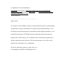
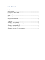
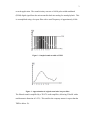
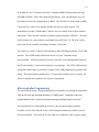
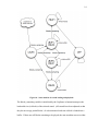
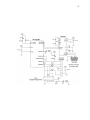
AN ABSTRACT OF THE THESIS OF Erin Sullivan for the degree of Honors Baccalaureate of Science in Electrical and Computer Engineering presented on June 1, 2010. Title: Design and Implementation a Capacitive Touch Children’s Guitar. Abstract approved: __________________________________________ Roger Traylor The Capacitive Touch Children’s Guitar is a fully functional electronic toy demonstrating an application of Cypress Semiconductor’s CapSense touch sensing technology. It was developed as a senior design project by myself and two other engineering students. I was responsible for the guitar’s LED lights, main microcontroller and sound storage and playback from a flash memory card. In addition, I built a flash memory programmer to load the sound data onto the flash card. This document presents a view of the overall design and an in-depth look at my contributions. Keywords: engineering, capacitive, guitar, music, toy Corresponding email address: [email protected] Design and Implementation of a Capacitive Touch Children’s Guitar by Erin Marie Sullivan A PROJECT submitted to Oregon State University University Honors College in partial requirement of the requirements for the degree of Honors Baccalaureate of Science in Electrical and Computer Engineering (Honors Scholar) Presented June 1, 2010 Commencement June 2010 Honors Baccalaureate of Science in Electrical and Computer Engineering project of Erin Sullivan presented on June 1, 2010. APPROVED: Mentor, representing Electrical and Computer Engineering Committee Member, representing Electrical and Computer Engineering Committee Member, representing Computer Science Head, School of Electrical Engineering and Computer Science Dean, University Honors College I understand that my project will become part of the permanent collection of Oregon State University, University Honors College. My signature below authorizes release of my project to any reader upon request. Erin Sullivan, Author ACKNOWLEDGEMENT First and foremost, thank you Casey Silbernagel and Randy Suhargo for their contributing work on the project. This project was one of the most fun and challenging I’ve ever done, and it was a success because of the great team behind it. I would like to thank our industry mentor, Robert Eilers, for providing the original idea for a touch-controlled music toy and for his continuous support of the project. I must also extend my sincere gratitude to Don Heer for taking time out of his busy schedule to help our group get on track during some difficult moments. Thank you to Roger Traylor for being the official mentor for this project and for always being an inspiration. Thanks also to Jed Irvine for being a friend and committee member. As I move forward in my life, I will never forget my experiences with all of you at Oregon State University. CONTRIBUTION OF CO-AUTHORS This paper describes a senior design project created by Casey Silbernagel, Randy Suhargo and myself. Some of their work has been included in the engineering design specification. Table of Contents Introduction......................................................................................................................... 1 Project Overview ................................................................................................................ 2 Overview of Co-Authors’ Work ......................................................................................... 2 Flash Memory ..................................................................................................................... 5 Lights .................................................................................................................................. 8 Microcontroller ................................................................................................................. 10 Microcontroller Programming .......................................................................................... 12 Conclusion ........................................................................................................................ 15 Works Cited ...................................................................................................................... 17 Appendix A - Project Schematic....................................................................................... 18 Appendix B - Flash Memory Programmer Schematic...................................................... 20 Appendix C - Microcontroller Code ................................................................................. 22 Appendix D - Flash Memory Code................................................................................... 30 Appendix E - MATLAB WAV conversion code ............................................................. 41 Table of Figures Figure 1 – Guitar Hero guitar with “strummer” and buttons on neck ................................ 1 Figure 2 - Sampled sound encoded as PWM ...................................................................... 3 Figure 3 - Approximation of original sound after low-pass filter....................................... 3 Figure 4 - Completed guitar in case.................................................................................... 4 Figure 5 - SD Card Programmer......................................................................................... 6 Figure 6 - Writing the flash memory from a PC terminal................................................... 8 Figure 7 - Initial light block design..................................................................................... 9 Figure 8 - Light block after rewiring ................................................................................ 10 Figure 9 - Stellaris LM3S811 Evaluation Kit ................................................................... 11 Figure 10 - State machine for sound loading and playback.............................................. 14 1 Introduction In the fall of 2009, I began working on the “Touch Controlled Music Player” with Casey Silbernagel and Randy Suhargo. The idea of using capacitive touch technology in a music-playing children’s toy was suggested by our mentor, Robert Eilers of Cypress Semiconductor, who was inspired by one of his son’s musical toys. A similar toy incorporating Cypress’ CapSense technology would be a fun project as well as a good demonstration of the uses of capacitive touch. We were given significant leeway with our design, and considered several ideas, such as a piano and turntable, before eventually deciding on the “Guitar Hero”-inspired toy guitar. Figure 1 – Guitar Hero guitar with “strummer” and buttons on neck In addition to the basic requirements of “plays music” and “contains Cypress CapSense technology”, the project had a few other requirements. It needed to be safe for children, durable enough to be dropped, have a battery life of at least three hours, and have physical buttons and LED lights to generate additional interest. 2 Project Overview The project design was completed fall term, following the requirements for the senior design class. We worked on building the guitar during winter and spring term and were able to complete construction by the Engineering Expo. The design required only a few minor adjustments during construction. At the simplest level, the guitar can be thought of as having inputs (mechanical buttons and touch sensitive strummer), outputs (sound and LEDs) and a control system (microcontroller and flash memory). In addition, the project required a custom guitarshaped enclosure. During project development and construction, I was responsible for the LED, flash memory, and microcontroller sections. Overview of Co-‐Authors’ Work As mentioned previously, the project was a group effort between Casey Silbernagel, Randy Suhargo, and myself. I will briefly review their contributions to the project (which are necessary for understanding how the guitar works) before examining my own work in detail. An essential component to any electronic device is power. Early on, we decided that the device would run at 3.3 volts and would be powered by commonly available batteries. The guitar was also required to have a battery life of three hours or more. Based on power budget calculations, we decided that four AA batteries connected to a UA78M00 fixed-voltage regulator would be an appropriate power source. Naturally, a guitar toy will be expected to play sound. The design of our guitar sound generation system was based heavily off an Atmel application note [1] describing a voice 3 recorder application. The sound circuitry converts a 16 kHz pulse-width modulated (PWM) digital signal from the microcontroller back into analog for sound playback. This is accomplished using a low-pass filter with a cutoff frequency of approximately 4 kHz. Figure 2 - Sampled sound encoded as PWM Figure 3 - Approximation of original sound after low-pass filter The filtered sound is amplified by a TPA731 audio amplifier, delivering 250 mW with a total harmonic distortion of 0.55%. This satisfies the company mentor’s request that the THD be below 1%. 4 The amplified sound is played through an 8-ohm speaker. A special requirement for the speaker was that it needed to be small enough to fit in the constrained space of the guitar case. One particularly unique aspect of the guitar project was the need for a custom-built case. The option of repurposing an existing case such as a Guitar Hero guitar was considered, but rejected due to the fact that the guitar had to be small enough for children age 3-5, and a gutted commercial product would be even more constrained in terms of internal space. Figure 4 - Completed guitar in case Our guitar case was modeled in SolidWorks and 3D printed at OSU. Before the Engineering Expo, the case was painted in OSU’s colors of orange and black. The backing is made of clear polycarbonate so the internal components can be seen. On the neck of the guitar, there are four spring-loaded buttons connected to internal switches. The “capacitive touch” aspect of the guitar can be seen on the “strings” area of the guitar picture above. Because we wanted a rather large “strumming pad”, we needed to implement a two-dimensional touchpad-style capacitive touch surface rather than the 5 simpler “slider” touch surface we had originally planned on implementing. This added some development time to the capacitive touch section. We used the CapSense CY8C20534 chip from Cypress to interpret the touch surface input and produce suitable outputs for the microcontroller. The CapSense chip also controls the six lights on either side of the touchpad; these will light up in sequence as a user slides his or her finger across. Flash Memory One of the most difficult aspects of the design and implementation of the project was figuring out how to store the sound data in a way that could easily be accessed by the microcontroller. Most microcontrollers contain less than 100 KB of onboard flash memory. This is a lot of memory for code storage, but insufficient for storing any kind of multimedia; a sound file even a few seconds long can be hundreds of kilobytes. (We had decided early on that our guitar should output “real” sampled guitar noises, not simple tones.) The first challenge was deciding which medium the data should be stored on. The aforementioned Atmel application note [1] used an external flash memory chip to store and play back recorded sound data. However, this solution was unsuitable for use in the guitar because there is no easy way to load data from an external source to the flash chip. Through my research I found that SD cards, commonly used in cameras, cell phones and other mobile devices, were also popular in microcontroller projects. The SD card can be accessed through a standard SPI interface available on most microcontrollers. Due to SD’s popularity, there is a large amount of code and documentation available on the web. 6 The cards are commonly available and inexpensive. It’s even possible to easily make SD card sockets by using MicroSD cards and soldering 0.1” header to the breakout adapter. One of the biggest appeals of using the SD card was the possibility that data could be loaded to the card directly from a computer. Further examination showed that this solution was not as easy as it looked. A computer operating system cannot access an SD card (or any other storage media) unless it has been formatted. In the case of flash memory, this usually means FAT16 or FAT32 formatting. However, from the perspective of the guitar microcontroller, accessing formatted data storage adds a significant layer of complexity and extra computation time. Ideally, the sound data should be written unformatted to the SD card and read directly. Figure 5 - SD Card Programmer The solution I came up with was to build a separate SD card programmer to load unformatted “raw” data directly to the SD card, which could then easily be accessed by the LM3S811 microcontroller simply by knowing the block number and length of the data to be read. This design is based on another project that uses an ATmega8 or 7 ATmega32 microcontroller to read from or write to an SD card. [2] Due to unavailability of the mega8 or mega32 at the time of building, I was forced to use an ATmega88 as a replacement, and modified the existing codebase to work with this microcontroller. Another difficulty was getting the code small enough to fit into the ATmega88’s 8K of internal Flash memory. The original code had been just small enough to squeeze onto the mega8, and with a small amount of tweaking fit on the mega88 as well. However, I needed to add one of the “advanced” features from the ATmega32 version of the code – the ability to write to multiple blocks at a time. I was able to accomplish this by cutting out unnecessary features (such as the ability to read or erase blocks) until the multiple block write function finally fit. The flash memory programmer has an RS-232 interface for use with a PC terminal program. Because my laptop does not have a serial port, I needed to use an off-the-shelf USB-serial adapter. I had no difficulty accessing the device using a standard terminal program. 8 Figure 6 - Writing the flash memory from a PC terminal The flash memory programmer proved to be an effective method for loading sound data onto the SD card. One downside was that it was unexpectedly slow – often taking upwards of an hour to transfer a single sound clip. However, the ability to load “raw” data, which could then be accessed directly by the microcontroller, significantly reduced the complexity of programming for the LM3S811. Lights I was responsible for the six LED lights on the top of the guitar’s neck. The initial LED design used only two GPIO from the microcontroller, with three LEDs each being controlled by a single GPIO. Because the microcontroller can only source or sink up to 8 9 mA of current per GPIO line, transistors were added to the design to allow approximately 13.3 mA of current through each LED. Figure 7 - Initial light block design During spring term, the group decided that it would be better if each light could be controlled separately. The microcontroller had four extra GPIOs, so there wasn’t a problem on that end. An unexpected difficulty came from the constrained size of the case. The protoboard containing the light components had to fit in a small area on top of the guitar and was already cramped. Building a new light board would have required additional labor and time, which we were already strained for. The old light board was simply rewired so each LED connected to the microcontroller, rather than being connected through the base of the transistor. The downside to this approach was that the 10 LEDs could no longer be driven by the transistors, and instead were driven by the microcontroller. This resulted in the LEDs becoming dimmer. Figure 8 - Light block after rewiring Microcontroller My largest responsibility on the touch controlled music player was the central microcontroller. The microcontroller is responsible for controlling the entire design. It must interpret the input from the CapSense controllers and physical buttons and send appropriate outputs to the light and sound blocks. Since sound data is too large to fit in a microcontroller's onboard flash memory, the microcontroller must also be capable of accessing an external memory at relatively high speeds. The device must run fast enough and contain enough memory to manage all these tasks at once. 11 I researched several microcontroller boards before deciding on the Stellaris LM3S811 Evaluation Kit from Luminary Micro (now owned by Texas Instruments). Using a microcontroller board, rather than a standalone microcontroller, is an obvious choice for a proof-of-concept prototype (as opposed to a commercially produced device). A microcontroller board will have easily accessible GPIO pins, which is especially important for chips that are only available in surface mount packages. Preferably, these pins will be spaced at a standard pitch (usually 0.1”) so the board can be mounted to headers and attached or detached from the rest of the system easily. Another mechanical consideration was the size of the board itself, given the constrained nature of the guitar case. The LM3S811 Evaluation Kit measures 3.5” x 1.5”, which is reasonably small. Figure 9 - Stellaris LM3S811 Evaluation Kit Other reasons the LM3S811 was a good candidate are that, first and foremost, it contained more than enough GPIO pins for the CapSense, buttons and lights. Second, it was capable of outputting a PWM signal with 16 bits of quantization at 16 KHz. It could also run SPI at speeds upwards of 2 MHz. Because the microcontroller would be outputting the sounds it accessed from the Flash memory via SPI, it was important that the SPI could run much faster than the PWM and not introduce any noticeable delay into sound playback. The microcontroller itself runs at up to 50 MHz, though I chose to run it 12 at 40 MHz for ease of frequency division. It contains 64KB of Flash memory for code and 8KB of SRAM. This is more than enough memory, even considering the two 512byte buffers needed for sound playback in RAM. The LM3S811 is built around an ARM Cortex-M3 core, which I was already familiar with from an earlier project. The manufacturer provides “StellarisWare” libraries for easy control of the various onboard subsystems. There are also a number of hobbyist projects using the LM3S811. The most useful of these was a project that accessed data from an SD card. [3] The code for this project was freely available, and using it saved me a lot of time. Two other nice “bonus” features of the board were the OLED display and the JTAG-USB interface. The OLED display allowed for the use of “print” functions on the microcontroller. While not strictly necessary, it was nice to have during initial testing of the SD card interface. I also used it to display error messages. The JTAG-USB interface meant that I did not have to purchase a separate JTAG-USB programmer to program and debug. The microcontroller board runs at 3.3V and draws around 80 mA of current. [4] This was deemed an acceptable level of power consumption. Microcontroller Programming The most difficult aspect of programming the microcontroller was reading the sound data from the SD card and outputting that data as a PWM signal. Compared to this task, implementation of the CapSense and button interrupts and light output was trivial. One issue that arose was the problem of how to convert sound samples (typically available as WAV files) into the 16-bit, 16 kHz sampled sounds that would be used on the microcontroller. Even if the WAV file could be re-sampled, I wasn’t going to spend 13 time figuring out how to decode a WAV file in the LM3S811 code. The solution I decided on was to use MATLAB and its “wavread” and “resample” functions to change WAV files to the required format. Once converted, the sounds were loaded to the SD card using the flash memory programmer. I obtained the sampled guitar sounds from the website “The Freesound Project” [6], which is a large database of sounds licensed under Creative Commons. In particular, the sounds I used were “that_beatles_chord” by “justkiddink” [6] and “chord1”, “chord2”, “chord3” and “chord5” by “NoiseCollector” [7]. To play back the sound as it was loaded from the SD card, I implemented a simple state machine. In order to avoid skipping in the sound playback, I needed to be able to read a block of sound data from the SD card while simultaneously playing the previous block out the PWM. I used two 512-byte buffers (512 bytes is the size of an SD card block) named buf0 and buf1. When an interrupt from the CapSense or buttons indicates that there is a sound to be played, the state machine will first enter the LBUF0 state and load the first block of the sound into buf0. (All sound locations and lengths are hardcoded using define statements.) The delay to load a single block is only a few milliseconds and too short to be detected by the user. 14 Figure 10 - State machine for sound loading and playback The blocks_remaining variable is initialized by the CapSense or button interrupt as the hardcoded size (in blocks) of the selected sound. (All sounds have been adjusted so that they do not occupy partial blocks.) It is decremented each time a block is loaded into a buffer. If there are still blocks remaining to be played, the state machine moves to either 15 the LBUF1_PBUF0 state or the LBUF0_PBUF1 state and loads the next block using SPI while outputting the previous block on the PWM. The state machine will wait in the current state until the PWM has finished outputting each encoded sample, as indicated by the cnt variable. (Since sound samples are 16-bit, there are 256 samples per block.) After all blocks have been read, the state machine will move to the PBUF0 or PBUF1 state, play the last block, then return to the OFF state. The rest of the microcontroller code was fairly trivial to implement. The CapSense chip outputs an active-low signal when “strummed”, which triggers an interrupt on the microcontroller. Initially, there were also interrupts associated with the buttons; these were later removed, so the guitar will only play sounds when the CapSense is touched. Holding buttons while strumming the CapSense causes different sounds to be played. The buttons also use standard GPIO, and are active-high. The LEDs, as noted earlier, are active-low. Conclusion In many ways, the touch-controlled guitar project was a natural extension of my other work with microcontrollers, including a test board I designed at Datalogic Scanning and the clock radio from ECE 473. The most challenging aspect of the project was the sound storage and playback; especially the unexpected need to build a separate flash memory programmer. In the end, my design worked successfully and the toy guitar outputs realistic-sounding guitar sounds when “strummed”. At present, there are a number of improvements I would consider implementing to improve on the guitar design. One improvement would be allowing the microcontroller 16 to read sound files from formatted SD cards. This would greatly simplify the process of loading sounds on the SD card by allowing them to be loaded directly from a computer. This would not have been a feasible addition during the initial implementation of the SD card interface, but would make a good improvement. I would also consider using a faster PWM to output sound data that had been sampled at a higher rate. Ideally, the PWM would run at 44.1 kHz (a standard sampling rate for audio files), which would allow the encoding of sounds encompassing the entire range of human hearing (approximately 20 Hz – 20 kHz). This would also require a change to the low-pass filter. I had a lot of fun working on the touch-controlled guitar. I’ve always been interested in microcontroller-based toys and this project provided an opportunity to create one in real life. Our Expo showing was successful and attracted a lot of attention from our target audience – young children and their parents. I couldn’t think of a better way to have finished off my five years as an undergraduate in Electrical and Computer Engineering. 17 Works Cited [1] AVR335: Digital Sound Recorder with AVR® and DataFlash®. Atmel, http://www.atmel.com/dyn/resources/prod_documents/doc1456.pdf, last accessed: 11/09 [2] SD Card Interfacing with AT mega8 / 32. Design with Microcontrollers, http://www.dharmanitech.com/2009/01/sd-card-interfacing-with-atmega8-fat32.html, last accessed: 11/09 [3] Video Frame Grabber. µelectronicsinfo, http://www.uelectronics.info/video-framegrabber, last accessed: 6/10 [4] LM3S811 Evaluation Kit User's Manual, Luminary Micro, http://www.luminarymicro.com/procutcs/eki-lm3s811.html, last accessed: 12/09 [5] The Freesound Project. http://www.freesound.org, last accessed: 6/10 [6] Sample: That Beatles chord.wav. The Freesound Project, http://www.freesound.org/samplesViewSingle.php?id=72557, last accessed: 6/10 [7] “Small Acoustic Guitar” by NoiseCollector. The Freesound Project, http://www.freesound.org/packsViewSingle.php?id=3716, last accessed: 6/10 18 Appendix A -‐ Project Schematic 19 20 Appendix B -‐ Flash Memory Programmer Schematic The flash memory programmer uses an ATmega88 microcontroller. It is adapted from the ATmega8-based design from “SD Card Interfacing with ATmega8 / 32”. [2] 21 22 Appendix C -‐ Microcontroller Code The microcontroller code is written in C for the Stellaris LM3S811 microcontroller. 23 SeniorDesign/microcontroller_code/sound_test/sound_test.c Page 1 //***************************************************************************** // Test the ability to read from the SD card. // spi_read_test.c // Erin Sullivan // 2.21.2010 //***************************************************************************** #include #include #include #include #include #include #include #include #include #include #include #include #include #include "inc/hw_types.h" "inc/hw_memmap.h" "inc/hw_ints.h" "driverlib/debug.h" "driverlib/sysctl.h" "driverlib/systick.h" "driverlib/ssi.h" "driverlib/gpio.h" "inc/hw_ssi.h" "drivers/display96x16x1.h" "lib/sd_spi.h" "driverlib/pwm.h" "driverlib/interrupt.h" <string.h> unsigned char buf0[512]; unsigned char buf1[512]; unsigned unsigned unsigned unsigned unsigned unsigned unsigned ) or not unsigned h led volatile int cnt = 0; int blocksRemaining; long sound; int offset; char sound_state = 0; int timeout = 0; char test_pin_on = 0; //the index of the sound data //block offset for reading from SD //state machine variable for sound playback //timeout //whether to autoéreset PC7 (test light/LED5 char test_led_count = 0; //use test pin to implement binary count wit unsigned long sound_locs[] = {300, 400, 1000, 1112, 1301, 1444, 2000, 2038, 2074, 2108, 3000, 3143, 3308, 3590, 6000}; unsigned int sound_lens[] = {17, 49, 112, 189, 143, 103, 38, 36, 34, 34, 143, 12, 282, 234, 50}; #define PWM_VALUE 8000 #define #define #define #define #define #define #define #define #define #define #define #define #define #define #define SOUND_HONK SOUND_CAT SOUND_CHORD1 SOUND_CHORD2 SOUND_CHORD3 SOUND_CHORD4 SOUND_TONEA SOUND_TONEB SOUND_TONED SOUND_TONEG SOUND_TBC SOUND_CHORD8 SOUND_CRIFF1 SOUND_FRIFF SOUND_NONE 0 1 2 3 4 5 6 7 8 9 10 11 12 13 14 //sound #define #define #define #define #define #define playback states OFF LBUF0 LBUF1_PBUF0 LBUF0_PBUF1 PBUF0 PBUF1 0 1 2 3 4 5 #define #define #define #define #define #define BUTTON1_SOUND BUTTON2_SOUND BUTTON3_SOUND BUTTON4_SOUND BUTTON1_ALT_SOUND BUTTON2_ALT_SOUND SOUND_CHORD1 SOUND_CHORD2 SOUND_CHORD3 SOUND_CHORD4 SOUND_TBC SOUND_HONK 24 SeniorDesign/microcontroller_code/sound_test/sound_test.c #define #define #define #define BUTTON3_ALT_SOUND BUTTON4_ALT_SOUND CAPSENSE_SOUND TEST_SOUND SOUND_CAT SOUND_TBC SOUND_TBC SOUND_CAT //button/capsense gpio bases #define BUTTON1_BASE #define BUTTON2_BASE #define BUTTON3_BASE #define BUTTON4_BASE #define CAPSENSE_BASE #define TEST_BASE GPIO_PORTD_BASE GPIO_PORTD_BASE GPIO_PORTB_BASE GPIO_PORTB_BASE GPIO_PORTB_BASE GPIO_PORTC_BASE //button/capsense gpio pins #define BUTTON1_PIN #define BUTTON2_PIN #define BUTTON3_PIN #define BUTTON4_PIN #define CAPSENSE_PIN #define TEST_PIN GPIO_PIN_4 GPIO_PIN_5 GPIO_PIN_0 GPIO_PIN_1 GPIO_PIN_4 GPIO_PIN_4 //LED gpio bases #define LED1_BASE #define LED2_BASE #define LED3_BASE #define LED4_BASE #define LED5_BASE #define LED6_BASE GPIO_PORTB_BASE GPIO_PORTC_BASE GPIO_PORTB_BASE GPIO_PORTD_BASE GPIO_PORTC_BASE GPIO_PORTC_BASE //LED gpio pins #define LED1_PIN #define LED2_PIN #define LED3_PIN #define LED4_PIN #define LED5_PIN #define LED6_PIN GPIO_PIN_6 GPIO_PIN_7 GPIO_PIN_5 GPIO_PIN_1 GPIO_PIN_5 GPIO_PIN_6 //LED bitfields #define LED1 #define LED2 #define LED3 #define LED4 #define LED5 #define LED6 Page 2 0x1 0x2 0x4 0x8 0x10 0x20 //LED physical locations #define LED_L_RED LED2 #define LED_L_YELLOW LED4 #define LED_L_GREEN LED3 #define LED_R_RED LED1 #define LED_R_YELLOW LED6 #define LED_R_GREEN LED5 #define TIMEOUT_MS 300000 //timeout value in ms //***************************************************************************** // //! \addtogroup example_list //! <h1>Hello World (hello)</h1> //! //! A very simple ``hello world'' example. It simply displays ``hello world'' //! on the LCD and is a starting point for more complicated applications. // //***************************************************************************** //***************************************************************************** // // The error routine that is called if the driver library encounters an error. // //***************************************************************************** #ifdef DEBUG void 25 SeniorDesign/microcontroller_code/sound_test/sound_test.c Page 3 __error__(char *pcFilename, unsigned long ulLine) { } #endif //Helper function to turn LEDs on/off. void LEDControl(int leds){ if(leds & LED1) GPIOPinWrite(LED1_BASE, LED1_PIN, 0); else GPIOPinWrite(LED1_BASE, LED1_PIN, LED1_PIN); if(leds & LED2) GPIOPinWrite(LED2_BASE, LED2_PIN, 0); else GPIOPinWrite(LED2_BASE, LED2_PIN, LED2_PIN); if(leds & LED3) GPIOPinWrite(LED3_BASE, LED3_PIN, 0); else GPIOPinWrite(LED3_BASE, LED3_PIN, LED3_PIN); if(leds & LED4) GPIOPinWrite(LED4_BASE, LED4_PIN, 0); else GPIOPinWrite(LED4_BASE, LED4_PIN, LED4_PIN); if(leds & LED5) GPIOPinWrite(LED5_BASE, LED5_PIN, 0); else GPIOPinWrite(LED5_BASE, LED5_PIN, LED5_PIN); } if(leds & LED6) GPIOPinWrite(LED6_BASE, LED6_PIN, 0); else GPIOPinWrite(LED6_BASE, LED6_PIN, LED6_PIN); //***************************************************************************** // // The PWM interrupt handler. // //***************************************************************************** void PWMIntHandler(void) { unsigned long ulStatus; unsigned long ulPeriod; unsigned int value; ); ); ulPeriod = SysCtlClockGet() / (4*PWM_VALUE); //play from buffer 0 if((sound_state == LBUF1_PBUF0) || (sound_state == PBUF0)){ value = buf0[2*cnt]; value += buf0[2*cnt+1] * 0x100; //convert chars to int cnt++; if (value > 65010) value = 65010; PWMPulseWidthSet(PWM_BASE, PWM_OUT_0, ulPeriod * (value + 1) / 65536 } else if((sound_state == LBUF0_PBUF1) || (sound_state == PBUF1)){ value = buf1[2*cnt]; value += buf1[2*cnt+1] * 0x100; //convert chars to int cnt++; if (value > 65010) value = 65010; PWMPulseWidthSet(PWM_BASE, PWM_OUT_0, ulPeriod * (value + 1) / 65536 } else { //50% duty cycle 26 SeniorDesign/microcontroller_code/sound_test/sound_test.c Page 4 PWMPulseWidthSet(PWM_BASE, PWM_OUT_0, ulPeriod / 2); cnt=256; //don't get stuck } // Get the interrrupt status. ulStatus = PWMGenIntStatus(PWM_BASE, PWM_GEN_0, true); // Clear the asserted interrupts. PWMGenIntClear(PWM_BASE, PWM_GEN_0, ulStatus); } //***************************************************************************** // // The GPIO Port B interrupt handler. (CapSense interrupt) // //***************************************************************************** void PortBIntHandler(void) { //Button 1 is pressed. if(GPIOPinRead(BUTTON1_BASE, BUTTON1_PIN)){ sound = sound_locs[BUTTON1_SOUND]; blocksRemaining = sound_lens[BUTTON1_SOUND]; LEDControl(LED_L_RED|LED_R_YELLOW|LED_L_GREEN); //button 2 is also pressed = play the alt sound if(GPIOPinRead(BUTTON2_BASE, BUTTON2_PIN)) { sound = sound_locs[BUTTON1_ALT_SOUND]; blocksRemaining = sound_lens[BUTTON1_ALT_SOUND]; } } //Button 2 is pressed. else if(GPIOPinRead(BUTTON2_BASE, BUTTON2_PIN)){ sound = sound_locs[BUTTON2_SOUND]; blocksRemaining = sound_lens[BUTTON2_SOUND]; LEDControl(LED_L_RED|LED_R_RED|LED_L_GREEN|LED_R_GREEN); //button 3 is also pressed = play the alt sound if(GPIOPinRead(BUTTON3_BASE, BUTTON3_PIN)) { sound = sound_locs[BUTTON2_ALT_SOUND]; blocksRemaining = sound_lens[BUTTON2_ALT_SOUND]; } } //Button 3 is pressed. else if(GPIOPinRead(BUTTON3_BASE, BUTTON3_PIN)){ sound = sound_locs[BUTTON3_SOUND]; blocksRemaining = sound_lens[BUTTON3_SOUND]; LEDControl(LED_R_RED|LED_L_YELLOW|LED_R_GREEN); //button 4 is also pressed = play the alt sound if(GPIOPinRead(BUTTON4_BASE, BUTTON4_PIN)) { sound = sound_locs[BUTTON3_ALT_SOUND]; blocksRemaining = sound_lens[BUTTON3_ALT_SOUND]; } } //Button 4 is pressed. else if(GPIOPinRead(BUTTON4_BASE, BUTTON4_PIN)){ sound = sound_locs[BUTTON4_SOUND]; blocksRemaining = sound_lens[BUTTON4_SOUND]; LEDControl(LED_L_YELLOW|LED_R_YELLOW|LED_R_RED|LED_L_GREEN); } //No buttons are pressed. else { sound = sound_locs[CAPSENSE_SOUND]; blocksRemaining = sound_lens[CAPSENSE_SOUND]; //cycle LEDs test_led_count++; if(test_led_count > 0x2F) test_led_count = 1; LEDControl(test_led_count); } sound_state = LBUF0; 27 SeniorDesign/microcontroller_code/sound_test/sound_test.c Page 5 cnt = 0; offset = 0; timeout = 0; } //***************************************************************************** // // The GPIO Port C interrupt handler. (Test button) // //***************************************************************************** void PortCIntHandler(void) { sound = sound_locs[TEST_SOUND]; blocksRemaining = sound_lens[TEST_SOUND]; test_led_count++; if(test_led_count > LED6) test_led_count = 0; LEDControl(test_led_count); cnt = 0; offset = 0; sound_state = LBUF0; timeout = 0; } //***************************************************************************** // // The idle function. Runs continuously when no other sounds are playing. // (Used for battery life testing.) // //***************************************************************************** void idle(void){ sound = sound_locs[SOUND_NONE]; blocksRemaining = sound_lens[SOUND_NONE]; test_led_count++; if(test_led_count > LED6) test_led_count = 1; LEDControl(test_led_count); cnt = 0; offset = 0; sound_state = LBUF0; } //***************************************************************************** // // The systick interrupt handler. Used for auto poweréoff. // //***************************************************************************** void SysTickIntHandler(void) { timeout++; if (timeout > (TIMEOUT_MS é 1)) { // Display96x16x1StringDraw("Entering Sleep", 0, 0); LEDControl(0); SysCtlSleep(); } } //***************************************************************************** // // Main function // //***************************************************************************** int main(void) { unsigned long ulPeriod; blocksRemaining = 0; sound = sound_locs[TEST_SOUND]; // // Set the clocking to run from the PLL / 5 = 40 MHz. SysCtlClockSet(SYSCTL_SYSDIV_5 | SYSCTL_USE_PLL | SYSCTL_OSC_MAIN | SYSCTL_XTAL_6MHZ); //PWM clock = 10 MHz 28 SeniorDesign/microcontroller_code/sound_test/sound_test.c SysCtlPWMClockSet(SYSCTL_PWMDIV_4); // Initialize the OLED display. Display96x16x1Init(false); // Enable the peripherals used. SysCtlPeripheralEnable(SYSCTL_PERIPH_PWM); SysCtlPeripheralEnable(SYSCTL_PERIPH_GPIOB); SysCtlPeripheralEnable(SYSCTL_PERIPH_GPIOC); SysCtlPeripheralEnable(SYSCTL_PERIPH_GPIOD); //Configure the Systick interrupt to fire every 1 ms. SysTickEnable(); SysTickPeriodSet(40000); SysTickIntEnable(); // Set GPIO D0 as a PWM pin. It is used to output the PWM0 signal. GPIOPinTypePWM(GPIO_PORTD_BASE, GPIO_PIN_0); //Set all buttons and CapSense as inputs. GPIOPinTypeGPIOInput(BUTTON1_BASE, BUTTON1_PIN); GPIOPinTypeGPIOInput(BUTTON2_BASE, BUTTON2_PIN); GPIOPinTypeGPIOInput(BUTTON3_BASE, BUTTON3_PIN); GPIOPinTypeGPIOInput(BUTTON4_BASE, BUTTON4_PIN); GPIOPinTypeGPIOInput(TEST_BASE, TEST_PIN); GPIOPinTypeGPIOInput(CAPSENSE_BASE, CAPSENSE_PIN); //Set all LEDs as output. GPIODirModeSet(LED1_BASE, LED1_PIN, GPIO_DIR_MODE_OUT); GPIODirModeSet(LED2_BASE, LED2_PIN, GPIO_DIR_MODE_OUT); GPIODirModeSet(LED3_BASE, LED3_PIN, GPIO_DIR_MODE_OUT); GPIODirModeSet(LED4_BASE, LED4_PIN, GPIO_DIR_MODE_OUT); GPIODirModeSet(LED5_BASE, LED5_PIN, GPIO_DIR_MODE_OUT); GPIODirModeSet(LED6_BASE, LED6_PIN, GPIO_DIR_MODE_OUT); //Set Buttons 1é4 as weak pullédowns. GPIOPadConfigSet(BUTTON1_BASE, BUTTON1_PIN, GPIO_STRENGTH_2MA, GPIO_PIN_TYPE_STD_WPD); GPIOPadConfigSet(BUTTON2_BASE, BUTTON2_PIN, GPIO_STRENGTH_2MA, GPIO_PIN_TYPE_STD_WPD); GPIOPadConfigSet(BUTTON3_BASE, BUTTON3_PIN, GPIO_STRENGTH_2MA, GPIO_PIN_TYPE_STD_WPD); GPIOPadConfigSet(BUTTON4_BASE, BUTTON4_PIN, GPIO_STRENGTH_2MA, GPIO_PIN_TYPE_STD_WPD); //Set CapSense as weak pulléup. GPIOPadConfigSet(CAPSENSE_BASE, CAPSENSE_PIN, GPIO_STRENGTH_2MA, GPIO_PIN_TYPE_STD_WPU); // Compute the PWM period based on the system clock. ulPeriod = SysCtlClockGet() / (4*PWM_VALUE); // Set the PWM period to 16 kHz. PWMGenConfigure(PWM_BASE, PWM_GEN_0, PWM_GEN_MODE_UP_DOWN | PWM_GEN_MODE_NO_SYNC); PWMGenPeriodSet(PWM_BASE, PWM_GEN_0, ulPeriod); // Set PWM0's duty cycle. PWMPulseWidthSet(PWM_BASE, PWM_OUT_0, ulPeriod / 2); //Enable the PWM interrupt to trigger on count zero IntMasterEnable(); IntEnable(INT_GPIOB); IntEnable(INT_GPIOC); IntEnable(INT_PWM0); IntEnable(FAULT_SYSTICK); //Enable the interrupts for the GPIO GPIOIntTypeSet(CAPSENSE_BASE, CAPSENSE_PIN, GPIO_LOW_LEVEL); GPIOIntTypeSet(TEST_BASE, TEST_PIN, GPIO_LOW_LEVEL); GPIOPinIntEnable(CAPSENSE_BASE, CAPSENSE_PIN); GPIOPinIntEnable(TEST_BASE, TEST_PIN); PWMGenIntTrigEnable(PWM_BASE, PWM_GEN_0, PWM_INT_CNT_ZERO); Page 6 29 SeniorDesign/microcontroller_code/sound_test/sound_test.c // Enable the PWM0 output signal. PWMOutputState(PWM_BASE, PWM_OUT_0_BIT, true); // Enable the PWM generator. PWMGenEnable(PWM_BASE, PWM_GEN_0); //Initialize SPI. spi_init(); //Initialize the SD card for SPI mode. if(sd_init()) Display96x16x1StringDraw("SD Init Failed", 0, 0); //turn off LEDs LEDControl(0); //Sound playback state machine. while(1){ switch(sound_state){ case LBUF0: sd_read_block(buf0, sound+offset); //get the data blocksRemainingéé; offset++; if(blocksRemaining) sound_state = LBUF1_PBUF0; else sound_state = PBUF0; break; case LBUF0_PBUF1: sd_read_block(buf0, sound+offset); //get the data blocksRemainingéé; offset++; while(cnt<255); //wait for PWM to finish with buf1 cnt = 0; if(blocksRemaining) sound_state = LBUF1_PBUF0; else sound_state = PBUF0; break; case LBUF1_PBUF0: sd_read_block(buf1, sound+offset); //get the data blocksRemainingéé; offset++; while(cnt<255); //wait for PWM to finish with buf0 cnt = 0; if(blocksRemaining) sound_state = LBUF0_PBUF1; else sound_state = PBUF1; break; case PBUF0: while(cnt<255); //wait for PWM to finish with buf0 cnt = 0; blocksRemainingéé; sound_state = OFF; break; case PBUF1: while(cnt<255); //wait for PWM to finsh with buf1 cnt = 0; blocksRemainingéé; sound_state = OFF; break; default: if(test_pin_on) //clear PC7 if we're using it to test interrupts GPIOPinWrite(TEST_BASE, TEST_PIN, 0); // idle(); } } } Page 7 30 Appendix D -‐ Flash Memory Code The flash memory code is written in C for the ATmega88. It is adapted from the ATmega8 code from “SD Card Interfacing with ATmega8 / 32”. [2] 31 ~/Documents/School/SeniorDesign/flashmem/write_mult_blocks_code/SD_main.c Page 1 //********************************************************** // **** MAIN routine FOR Interfacing microSD/SD CARD ****** //********************************************************** //Controller: ATmega8 (Clock: 8 Mhzéinternal) //Compiler: AVRéGCC //Version : 2.1 //Author: CC Dharmani, Chennai (India) //Modified by Erin Sullivan for use with ATmega88 // www.dharmanitech.com //Date: 26 Feb 2009 //******************************************************** //Link to the Post: http://www.dharmanitech.com/2009/01/sdécardéinterfacingéwithéatm ega8éfat32.html #define F_CPU 8000000UL #include <avr/io.h> #include <avr/pgmspace.h> #include <avr/interrupt.h> #include <util/delay.h> #include "SPI_routines.h" #include "SD_routines.h" #include "UART_routines.h" #ifndef FAT_DISABLE //#include "FAT32.h" #endif volatile volatile volatile volatile volatile unsigned unsigned unsigned unsigned unsigned long long char long int //freq 8 MHz startBlock; totalBlocks; buffer[512]; firstDataSector, rootCluster, totalClusters; bytesPerSector, sectorPerCluster, reservedSectorCount; void port_init(void) { DDRB = 0xEF; //MISO line i/p, rest o/p PORTB = 0xEF; PORTC = 0x00; DDRC = 0x00; DDRD = 0x06; PORTD = 0x00; } //UART0 initialize // desired baud rate: 38400 // actual: baud rate:19231 (0.2%) // char size: 8 bit // parity: Disabled void uart0_init(void) { UCSR0B = 0x00; //disable while setting baud rate UCSR0A = 0x00; UCSR0C = 0x06; UBRR0L = 0x0C; //set baud rate lo UBRR0H = 0x00; //set baud rate hi UCSR0B = (1<<RXEN0)|(1<<TXEN0); } //call this routine to initialize all peripherals void init_devices(void) { cli(); port_init(); spi_init(); uart0_init(); MCUCR = 0x00; // GICR = 0x00; EIFR = 0x00; // TIMSK = 0x00; //timer interrupt sources TIMSK0 = 0x00; //all peripherals are now initialized } 32 ~/Documents/School/SeniorDesign/flashmem/write_mult_blocks_code/SD_main.c Page 2 int main(void) { unsigned char option, error, data, FAT32_active; unsigned int i; unsigned char fileName[13]; _delay_ms(100); //delay for VCC stabilization init_devices(); PORTD |= 0x04; //switching ON the LED (for testing purpose only) TX_NEWLINE; TX_NEWLINE; transmitString_F (PSTR("***********************************")); TX_NEWLINE; transmitString_F (PSTR(" Dharmani's microSD Card Testing..")); TX_NEWLINE; transmitString_F (PSTR("***********************************")); TX_NEWLINE; SD_init(); SPI_HIGH_SPEED; _delay_ms(1); //SCK é 4 MHz // #ifndef FAT_DISABLE // FAT32_active = 1; // error = getBootSectorData (); //read boot sector and keep necessary data in globa l variables // if(error) // { // transmitString_F (PSTR("FAT32 not found!")); //FAT32 incompatible drive // FAT32_active = 0; // } // #endif // // #ifdef FAT_DISABLE // transmitString_F (PSTR("FAT32 not found!")); //FAT32 incompatible drive // FAT32_active = 0; // #endif while(1) { TX_NEWLINE; transmitString_F(PSTR("Press TX_NEWLINE; option = receiveByte(); TX_NEWLINE; #ifndef SINGLE_DISABLE transmitString_F(PSTR("> 0 : TX_NEWLINE; transmitString_F(PSTR("> 1 : TX_NEWLINE; transmitString_F(PSTR("> 2 : #endif any key...")); Erase Blocks")); Write single Block")); Read single Block")); TX_NEWLINE; transmitString_F(PSTR("> 3 : Write multiple Blocks")); #ifndef FAT_TESTING_ONLY TX_NEWLINE; transmitString_F(PSTR("> 4 : Read multiple Blocks")); #endif #ifndef FAT_DISABLE TX_NEWLINE; transmitString_F(PSTR("> 5 : Get file list")); TX_NEWLINE; transmitString_F(PSTR("> 6 : Read File")); TX_NEWLINE; transmitString_F(PSTR("> 7 : Create File")); 33 ~/Documents/School/SeniorDesign/flashmem/write_mult_blocks_code/SD_main.c Page 3 TX_NEWLINE; transmitString_F(PSTR("> 8 : Delete File")); TX_NEWLINE; transmitString_F(PSTR("> 9 : Read SD Memory Capacity (Total/Free)")); #endif TX_NEWLINE; TX_NEWLINE; transmitString_F(PSTR("> Select Option (0é9): ")); /*WARNING: If option 0, 1 or 3 is selected, the card may not be detected by PC/Lapto p again, as it disturbs the FAT format, and you may have to format it again with FAT32. This options are given for learning the raw data transfer to & from the SD Card*/ option = receiveByte(); transmitByte(option); if(option >= 0x35 && option <= 0x39) //options 5 to 9 disabled if FAT32 not found { if(!FAT32_active) { TX_NEWLINE; TX_NEWLINE; transmitString_F(PSTR("FAT32 options disabled!")); continue; } } if((option >= 0x30) && (option <=0x34)) //get starting block address for options 0 t o 4 { TX_NEWLINE; TX_NEWLINE; transmitString_F(PSTR("Enter the Block number (0000é9999):")); data = receiveByte(); transmitByte(data); startBlock = (data & 0x0f) * 1000; data = receiveByte(); transmitByte(data); startBlock += (data & 0x0f) * 100; data = receiveByte(); transmitByte(data); startBlock += (data & 0x0f) * 10; data = receiveByte(); transmitByte(data); startBlock += (data & 0x0f); TX_NEWLINE; } totalBlocks = 1; //#ifndef FAT_TESTING_ONLY if((option == 0x30) || (option == 0x33) || (option == 0x34)) //get total number of b locks for options 0, 3 or 4 { TX_NEWLINE; TX_NEWLINE; transmitString_F(PSTR("How many blocks? (000é999):")); data = receiveByte(); transmitByte(data); totalBlocks = (data & 0x0f) * 100; data = receiveByte(); transmitByte(data); totalBlocks += (data & 0x0f) * 10; data = receiveByte(); transmitByte(data); totalBlocks += (data & 0x0f); TX_NEWLINE; } //#endif switch (option) { #ifndef SINGLE_DISABLE case '0': //error = SD_erase (block, totalBlocks); error = SD_erase (startBlock, totalBlocks); 34 ~/Documents/School/SeniorDesign/flashmem/write_mult_blocks_code/SD_main.c Page 4 TX_NEWLINE; if(error) transmitString_F(PSTR("Erase failed..")); else transmitString_F(PSTR("Erased!")); break; case '1': TX_NEWLINE; transmitString_F(PSTR(" Enter text (NEVER ENDING):")); i=0; do { data = receiveByte(); transmitByte(data); buffer[i++] = data; // if(data == '\r') //append 'newline' character whenevr 'carriag e return' is received // { // transmitByte('\n'); // buffer[i++] = '\n'; // } if(i == 512) break; }//while (data != '~'); while(1); error = SD_writeSingleBlock (startBlock); TX_NEWLINE; TX_NEWLINE; if(error) transmitString_F(PSTR("Write failed..")); else transmitString_F(PSTR("Write successful!")); break; case '2': error = SD_readSingleBlock (startBlock); TX_NEWLINE; if(error) transmitString_F(PSTR("Read failed..")); else { for(i=0;i<512;i++) { //if(buffer[i] == '~') break; transmitByte(buffer[i]); } TX_NEWLINE; TX_NEWLINE; transmitString_F(PSTR("Read successful!")); } break; //next two options will work only if following macro is cleared from SD_routines.h #endif case '3': error = SD_writeMultipleBlock (startBlock, totalBlocks); TX_NEWLINE; if(error) transmitString_F(PSTR("Write failed..")); else transmitString_F(PSTR("Write successful!")); break; #ifndef FAT_TESTING_ONLY case '4': error = SD_readMultipleBlock (startBlock, totalBlocks); TX_NEWLINE; if(error) transmitString_F(PSTR("Read failed..")); else transmitString_F(PSTR("Read successful!")); break; #endif #ifndef FAT_DISABLE case '5': TX_NEWLINE; 35 ~/Documents/School/SeniorDesign/flashmem/write_mult_blocks_code/SD_main.c Page 5 findFiles(GET_LIST,0); break; case '6': case '7': case '8': TX_NEWLINE; TX_NEWLINE; transmitString_F(PSTR("Enter file name: ")); for(i=0; i<13; i++) fileName[i] = 0x00; //clearing any previously stored file name i=0; while(1) { data = receiveByte(); if(data == '\r') break; //'ENTER' key pressed if(data == 0x08) //'Back Space' key pressed { if(i != 0) { transmitByte(data); transmitByte(' '); transmitByte(data); iéé; } continue; } if(data <0x20 || data > 0x7e) continue; //check for valid English text character transmitByte(data); fileName[i++] = data; if(i==13){transmitString_F(PSTR(" file name too long..")); break;} } if(i>12) break; TX_NEWLINE; if(option == '6') readFile( READ, fileName); if(option == '7') createFile(fileName); if(option == '8') deleteFile(fileName); break; case '9': memoryStatistics(); break; #endif default: TX_NEWLINE; TX_NEWLINE; transmitString_F(PSTR(" Invalid option!")); TX_NEWLINE; } TX_NEWLINE; } return 0; } //********** END *********** www.dharmanitech.com ************* 36 ~/Documents/School/SeniorDesign/flashmem/write_mult_blocks_code/SD_routines.c Page 1 //************************************************************** // ****** FUNCTIONS FOR SD RAW DATA TRANSFER ******* //************************************************************** //Controller: ATmega8 (Clock: 8 Mhzéinternal) //Compiler: AVRéGCC //Version : 2.0 //Author: CC Dharmani, Chennai (India) //Modified by Erin Sullivan for use with ATmega88 // www.dharmanitech.com //Date: 26 Feb 2009 //************************************************************** //Link to the Post: http://www.dharmanitech.com/2009/01/sdécardéinterfacingéwithéatm ega8éfat32.html //************************************************** // ***** SOURCE FILE : SD_routines.c ****** //************************************************** #include <avr/io.h> #include <avr/pgmspace.h> #include "SPI_routines.h" #include "SD_routines.h" #include "UART_routines.h" //****************************************************************** //Function: to initialize the SD card in SPI mode //Arguments: none //return: unsigned char; will be 0 if no error, // otherwise the response byte will be sent //****************************************************************** unsigned char SD_init(void) { unsigned char i, response, retry=0 ; SD_CS_ASSERT; do { for(i=0;i<10;i++) SPI_transmit(0xff); response = SD_sendCommand(GO_IDLE_STATE, 0);//send 'reset & go idle' command retry++; if(retry>0xfe) {transmitString_F(PSTR("SD init fail..")); return 1; }//time out } while(response != 0x01); SD_CS_DEASSERT; SPI_transmit (0xff); SPI_transmit (0xff); retry = 0; do { response = SD_sendCommand(SEND_OP_COND, 0); //activate card's initialization pro cess response = SD_sendCommand(SEND_OP_COND, 0); //resend command (for compatibility with some cards) retry++; if(retry>0xfe) return 1; //time out }while(response); SD_sendCommand(CRC_ON_OFF, OFF); //disable CRC; deafault é CRC disabled in SPI mode SD_sendCommand(SET_BLOCK_LEN, 512); //set block size to 512 return 0; //normal return } //****************************************************************** //Function: to send a command to SD card //Arguments: unsigned char (8ébit command value) // & unsigned long (32ébit command argument) //return: unsigned char; response byte //****************************************************************** 37 ~/Documents/School/SeniorDesign/flashmem/write_mult_blocks_code/SD_routines.c Page 2 unsigned char SD_sendCommand(unsigned char cmd, unsigned long arg) { unsigned char response, retry=0; SD_CS_ASSERT; SPI_transmit(cmd | 0x40); //send command, first two bits always '01' SPI_transmit(arg>>24); SPI_transmit(arg>>16); SPI_transmit(arg>>8); SPI_transmit(arg); SPI_transmit(0x95); while((response = SPI_receive()) == 0xff) //wait response if(retry++ > 0xfe) break; //time out error SPI_receive(); //extra 8 CLK SD_CS_DEASSERT; return response; //return state } #ifndef SINGLE_DISABLE //***************************************************************** //Function: to erase specified no. of blocks of SD card //Arguments: none //return: unsigned char; will be 0 if no error, // otherwise the response byte will be sent //***************************************************************** unsigned char SD_erase (unsigned long startBlock, unsigned long totalBlocks) { unsigned char response; response = SD_sendCommand(ERASE_BLOCK_START_ADDR, startBlock<<9); //send starting bl ock address if(response != 0x00) //check for SD status: 0x00 é OK (No flags set) return response; response = SD_sendCommand(ERASE_BLOCK_END_ADDR,(startBlock + totalBlocks é 1)<<9); / /send end block address if(response != 0x00) return response; response = SD_sendCommand(ERASE_SELECTED_BLOCKS, 0); //erase all selected blocks if(response != 0x00) return response; return 0; //normal return } #endif //****************************************************************** //Function: to read a single block from SD card //Arguments: none //return: unsigned char; will be 0 if no error, // otherwise the response byte will be sent //****************************************************************** unsigned char SD_readSingleBlock(unsigned long startBlock) { unsigned char response; unsigned int i, retry=0; response = SD_sendCommand(READ_SINGLE_BLOCK, startBlock<<9); //read a Block command //block address converted to starting address of 512 byte Block if(response != 0x00) //check for SD status: 0x00 é OK (No flags set) return response; SD_CS_ASSERT; while(SPI_receive() != 0xfe) //wait for start block token 0xfe (0x11111110) if(retry++ > 0xfffe){SD_CS_DEASSERT; return 1;} //return if timeéout for(i=0; i<512; i++) //read 512 bytes 38 ~/Documents/School/SeniorDesign/flashmem/write_mult_blocks_code/SD_routines.c Page 3 buffer[i] = SPI_receive(); SPI_receive(); //receive incoming CRC (16ébit), CRC is ignored here SPI_receive(); SPI_receive(); //extra 8 clock pulses SD_CS_DEASSERT; return 0; } //****************************************************************** //Function: to write to a single block of SD card //Arguments: none //return: unsigned char; will be 0 if no error, // otherwise the response byte will be sent //****************************************************************** unsigned char SD_writeSingleBlock(unsigned long startBlock) { unsigned char response; unsigned int i, retry=0; response = SD_sendCommand(WRITE_SINGLE_BLOCK, startBlock<<9); //write a Block comman d if(response != 0x00) //check for SD status: 0x00 é OK (No flags set) return response; SD_CS_ASSERT; SPI_transmit(0xfe); //Send start block token 0xfe (0x11111110) for(i=0; i<512; i++) //send 512 bytes data SPI_transmit(buffer[i]); SPI_transmit(0xff); SPI_transmit(0xff); //transmit dummy CRC (16ébit), CRC is ignored here response = SPI_receive(); if( (response & 0x1f) != 0x05) //response= 0xXXX0AAA1 ; AAA='010' é data accepted { //AAA='101'édata rejected due to CRC error SD_CS_DEASSERT; //AAA='110'édata rejected due to write error return response; } while(!SPI_receive()) //wait for SD card to complete writing and get idle if(retry++ > 0xfffe){SD_CS_DEASSERT; return 1;} SD_CS_DEASSERT; SPI_transmit(0xff); e SD_CS_ASSERT; //just spend 8 clock cycle delay before reasserting the CS lin //reéasserting the CS line to verify if card is still busy while(!SPI_receive()) //wait for SD card to complete writing and get idle if(retry++ > 0xfffe){SD_CS_DEASSERT; return 1;} SD_CS_DEASSERT; return 0; } #ifndef FAT_TESTING_ONLY //*************************************************************************** //Function: to read multiple blocks from SD card & send every block to UART //Arguments: none //return: unsigned char; will be 0 if no error, // otherwise the response byte will be sent //**************************************************************************** unsigned char SD_readMultipleBlock (unsigned long startBlock, unsigned long totalBlo cks) { unsigned char response; unsigned int i, retry=0; 39 ~/Documents/School/SeniorDesign/flashmem/write_mult_blocks_code/SD_routines.c Page 4 retry = 0; response = SD_sendCommand(READ_MULTIPLE_BLOCKS, startBlock <<9); //read a Block comm and //block address converted to starting address of 512 byte Block if(response != 0x00) //check for SD status: 0x00 é OK (No flags set) return response; SD_CS_ASSERT; while( totalBlocks ) { retry = 0; while(SPI_receive() != 0xfe) //wait for start block token 0xfe (0x11111110) if(retry++ > 0xfffe){SD_CS_DEASSERT; return 1;} //return if timeéout for(i=0; i<512; i++) //read 512 bytes buffer[i] = SPI_receive(); SPI_receive(); //receive incoming CRC (16ébit), CRC is ignored here SPI_receive(); SPI_receive(); //extra 8 cycles TX_NEWLINE; transmitString_F(PSTR(" ééééééééé ")); TX_NEWLINE; for(i=0; i<512; i++) //send the block to UART { if(buffer[i] == '~') break; transmitByte ( buffer[i] ); } } TX_NEWLINE; transmitString_F(PSTR(" ééééééééé ")); TX_NEWLINE; totalBlockséé; SD_sendCommand(STOP_TRANSMISSION, 0); //command to stop transmission SD_CS_DEASSERT; SPI_receive(); //extra 8 clock pulses return 0; } #endif //*************************************************************************** //Function: to receive data from UART and write to multiple blocks of SD card //Arguments: none //return: unsigned char; will be 0 if no error, // otherwise the response byte will be sent //**************************************************************************** unsigned char SD_writeMultipleBlock(unsigned long startBlock, unsigned long totalBlo cks) { unsigned char response, data; unsigned int i, retry=0; unsigned long blockCounter=0, size; response = SD_sendCommand(WRITE_MULTIPLE_BLOCKS, startBlock<<9); //write a Block com mand if(response != 0x00) //check for SD status: 0x00 é OK (No flags set) return response; SD_CS_ASSERT; TX_NEWLINE; transmitString_F(PSTR(" Enter text (NEVER ENDING): ")); TX_NEWLINE; while( blockCounter < totalBlocks ) 40 ~/Documents/School/SeniorDesign/flashmem/write_mult_blocks_code/SD_routines.c Page 5 { i=0; for(i=0;i<512;i++) { data = receiveByte(); transmitByte(data); buffer[i] = data; } // TX_NEWLINE; // transmitString_F(PSTR(" éééé ")); // TX_NEWLINE; SPI_transmit(0xfc); //Send start block token 0xfc (0x11111100) for(i=0; i<512; i++) //send 512 bytes data SPI_transmit( buffer[i] ); SPI_transmit(0xff); //transmit dummy CRC (16ébit), CRC is ignored here SPI_transmit(0xff); response = SPI_receive(); if( (response & 0x1f) != 0x05) //response= 0xXXX0AAA1 ; AAA='010' é data accepted { //AAA='101'édata rejected due to CRC error SD_CS_DEASSERT; //AAA='110'édata rejected due to write error return response; } while(!SPI_receive()) //wait for SD card to complete writing and get idle if(retry++ > 0xfffe){SD_CS_DEASSERT; return 1;} } SPI_receive(); //extra 8 bits blockCounter++; SPI_transmit(0xfd); //send 'stop transmission token' retry = 0; while(!SPI_receive()) //wait for SD card to complete writing and get idle if(retry++ > 0xfffe){SD_CS_DEASSERT; return 1;} SD_CS_DEASSERT; SPI_transmit(0xff); //just spend 8 clock cycle delay before reasserting the CS signa l SD_CS_ASSERT; //re assertion of the CS signal is required to verify if card is still busy while(!SPI_receive()) //wait for SD card to complete writing and get idle if(retry++ > 0xfffe){SD_CS_DEASSERT; return 1;} SD_CS_DEASSERT; return 0; } //********************************************* //******** END ****** www.dharmanitech.com ***** 41 Appendix E -‐ MATLAB WAV conversion code The MATLAB script converts a WAV file into a format appropriate for use by the microcontroller. 42 SeniorDesign/flashmem/test_data/wav_convert.m [wav, rate, bits] = wavread('sound.wav') wav = resample(wav, 16000, rate) %resample the sound at 16 kHz wav = wav+1 wav = wav(:,1).*32768 é 1 wav = uint16(wav) % convert to unsigned 16ébit integer fid_txt = fopen('sound.txt', 'wt') fid_bin = fopen('sound', 'wt') fprintf(fid_txt, '%04X\n', wav); fwrite(fid_bin, wav, 'uint16', 0, 'l'); Page 1