1
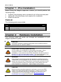
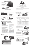
PCIe Link Kit User Manual PCI Express® Link Kit Model: PEX8G2-LINK Copyright © 2013 Mission Technology Group, Inc. - DBA Magma This publication is protected by Federal Copyright Law, with all rights reserved. No part of this publication may be copied, photocopied, reproduced, stored in a retrieval system, translated, transmitted or transcribed, in any form or by any means manual, electric, electronic, electro-magnetic, mechanical, optical or otherwise, in whole or in part without prior written consent from Magma. Limitation of Liability Information presented by Magma in this guide is believed to be accurate and reliable. However, Magma assumes no responsibility for its use. No license is granted by implication or otherwise to any rights of Magma. Product specifications and prices are subject to change without notice. Trademark References Trademarks and registered trademarks are proprietary to their respective manufacturers. M A G M A Table of Contents PREFACE ......................................................................................... III Advisories.......................................................................................... iii Safety Instructions ............................................................................. iv When Working Inside a Computer ...................................................... iv Protecting Against Electrostatic Discharge ........................................... v CHAPTER 1 - PRE-INSTALLATION ................................................... 6 Parts List ............................................................................................ 6 CHAPTER 2 HARDWARE INSTALLATION .................................... 6 Install PCI Express Interface Cards ..................................................... 8 Install host interface card (HIF) ....................................................................... 8 Install Expansion interface card (EIF) ............................................................. 9 I2C-over-iPass Communication Kit (Optional) .............................................. 11 Software Driver Installation:........................................................................... 12 Driver Installation ........................................................................................... 13 CHAPTER 3 VERIFY INSTALLATION .......................................... 14 Windows .......................................................................................... 14 Mac OS X......................................................................................... 15 Expansion Slot Utility ..................................................................................... 15 Apple System Profiler........................................................................ 16 RedHat Linux.................................................................................... 18 The Alternate Function DIP Switch (Magma Expansion Board Only) ... 19 APPENDIX A NEED MORE PCIE SLOTS?.................................... 20 Multiple PCIe Expansion System Configurations ................................ 20 APPENDIX C COMPLIANCE ........................................................ 22 FCC ................................................................................................................ 22 CE ................................................................................................................... 22 i M A G M A Preface Advisories Five types of advisories are used throughout this manual to provide helpful information, or to alert you to the potential for hardware damage or personal injury. They are Note, Important, Caution, Warning, and Danger. The following is an example of each type of advisory. NOTE Used to amplify or explain a comment related to procedural steps or text. IMPORTANT Used to indicate an important piece of information or a special “tip” to help you CAUTION Used to indicate and prevent the following procedure or step from causing damage to the equipment. WARNING Used to indicate and prevent the following step from causing injury. DANGER or STOP Used to indicate and prevent the following step from causing serious injury or significant data loss. COMPATIBILITY ISSUE Used to indicate a known or potential compatibility issue between Magma and non-Magma hardware that may cause malfunction. Disclaimer: We have attempted to identify most situations that may pose a danger, warning, or caution condition in this manual. However, Magma does not claim to have covered all situations that might require the use of a Caution, Warning, or Danger indicator. iii M A G M A Safety Instructions Always use caution when servicing any electrical component. Before handling the Magma PCI-Express Expansion chassis, read the following instructions and safety guidelines to prevent damage to the product and to ensure your own personal safety. Refer to the “Advisories” section for advisory conventions used in this manual, including the distinction between Danger, Warning, Caution, Important, and Note. ¨ Always use caution when handling/operating the computer. Only qualified, experienced, authorized electronics personnel should access the interior of the computer and expansion system per UL and IEC 60950-1 ¨ The power supplies produce high voltages and energy hazards, which can cause bodily harm. ¨ Use extreme caution when installing or removing components. Refer to the installation instructions in this manual for precautions and procedures. If you have any questions, please contact Magma Technical Support. WARNING High voltages are present inside the expansion chassis when the unit’s power cord is plugged into an electrical outlet. Disconnect the power cord from the AC inlet before removing the system’s cover. Never modify or remove the radio frequency interference shielding from your workstation or expansion unit. To do so may cause your installation to produce emissions that could interfere with other electronic equipment in the area of your system. When Working Inside a Computer Before taking covers off a computer, perform the following steps: 1. Turn off the computer and any peripheral devices. 2. Disconnect the computer and peripheral power cords from their AC outlets or inlets in order to prevent electric shock or system board damage. 3. Disconnect any telephone or telecommunications lines from the computer. In addition, take note of these safety guidelines when appropriate: ¨ iv To help avoid possible damage to systems boards, wait five seconds after turning off the computer before removing a M A G M A component, removing a system board, or disconnecting a peripheral device from the computer. ¨ When you disconnect a cable, pull on its connector or on its strain-relief loop, not on the cable itself. Some cables have a connector with locking tabs. If you are disconnecting this type of cable, press in on the locking tabs before disconnecting the cable. As you pull connectors apart, keep them evenly aligned to avoid bending any connector pins. Also, before connecting a cable, make sure both connectors are correctly oriented and aligned. CAUTION Do not attempt to service the system yourself except as explained in this manual. Follow installation instructions closely. Protecting Against Electrostatic Discharge Electrostatic Discharge (ESD) Warning Electrostatic Discharge (ESD) is the enemy of semiconductor devices. You should always take precautions to eliminate any electrostatic charge from your body and clothing before touching any semiconductor device or card by using an electrostatic wrist strap and/or rubber mat. Static electricity can harm system boards. Perform service at an ESD workstation and follow proper ESD procedures to reduce the risk of damage to components. Magma strongly encourages you to follow proper ESD procedures, which can include wrist straps and smocks, when servicing equipment. You can also take the following steps to prevent damage from electrostatic discharge (ESD): ¨ When unpacking a static-sensitive component from its shipping carton, do not remove the component’s anti-static packaging material until you are ready to install the component in a computer. Just before unwrapping the anti-static packaging, be sure you are at an ESD workstation or are grounded. ¨ When transporting a sensitive component, first place it in an anti-static container or packaging. ¨ Handle all sensitive components at an ESD workstation. If possible, use anti-static floor pads and workbench pads. Handle components and boards with care. Don’t touch the components or contacts on a board. Hold a board by its edges or by its metal mounting bracket. v M A G M A Chapter 1 - Pre-Installation Before using the Magma expansion chassis you should perform the following steps: · · · Inventory the shipping carton contents for all of the required parts Gather all of the necessary tools required for installation Read this manual Parts List The following parts are provided: Qty Item 1 1 or 3-meter shielded iPass™ cable 2 Half-height PCI Express host card Chapter 2 Hardware Installation The following steps will guide you through the installation of your Magma expansion system. CAUTION Hardware installation shall be performed only by qualified service personnel per UL and IEC 60950-1. Electrostatic Discharge (ESD) Warning All PCI cards are susceptible to electrostatic discharge. When moving PCI cards, it is best to carry the cards in anti-static packaging. If you need to set a PCIe card down, be sure to place it inside or on top of an anti-static surface. For more information, see “Protecting Against Electrostatic Discharge” in the Preface. WARNING High voltages are present inside the expansion chassis when the unit’s power cord is plugged into an electrical outlet. Disconnect the power cord from the AC outlet before removing the enclosure cover. Turning the system power off at the power on/off switch does not remove power to components. High voltage is still present. CAUTION Before touching anything inside the enclosure, move to an ESD station and follow proper ESD procedures. Failure to do so may result in electrostatic discharge, damaging the computer or its components. For more information, see “Protecting Against Electrostatic Discharge” in the Preface. 6 M A G M A STOP If your Magma expansion chassis was not purchased directly from Magma, you must check to ensure that it doesn’t contain any preinstalled PCIe cards. Check the rear side of the chassis to see if any PCIe cards are visible in the slots. If you see a PCIe card, you should continue installation using instructions provided by your dealer. If no separate instructions are available, remove the cover by using instructions in Chapter 4 Install Cards and Drives. Then remove the card(s) as normal. If no PCIe card is visible, then continue with the cable installation. 7 M A G M A Install PCI Express Interface Cards Install host interface card (HIF) Begin the installation of your PCI Express (PCIe) host card by first powering down your computer. Use the procedures for shutting down your operating system and shutting off power to your system provided in your owner’s manual or system documentation. The PCIe host card is a “half-height,” x8-capable PCIe card mounted to a “full-height” bracket as shown below: For low profile case applications, you may need to change the mounting bracket to the low profile bracket that shipped with your system. This is done by removing the screws that hold the card to the bracket. Be sure you are using proper ESD procedures when completing this action. Once the host computer is off and all power cords are disconnected from the AC outlet, remove the cover and insert the PCI Express host card into a vacant x8 (or x16) PCIe slot by gently pushing the card until it is firmly seated. Then secure the card to the slot with a mounting screw. Notice that the PCI Express slots are located at a greater distance from the edge of the computer’s motherboard than are the standard PCI slots as illustrated in the following figure. 8 M A G M A STOP YOU MUST ONLY INSTALL THE PCIe HOST CARD INTO A PCI EXPRESS SLOT. Only use cards WITH brackets. This will ensure that your PCIe host card can only be inserted into a PCIe slot. Although PCI Express cards without brackets may fit into conventional PCI slots, you run the risk of damaging the PCI Express host card if you insert it into a PCI slot. Please ensure that your host computer has PCI Express slots and install the host card only into a PCI Express slot. For more information on using PCIe cards, please refer to your computer’s user manual or system documentation. Next check the DIP switch settings on the Magma Host Card as shown: Host /Expansion Switch (Default Host): As long as the card is used as Host i.e. installed in your PC, the switch should remain OFF. Move it to the ON position only if the same card is used as an Expansion Interface (EIF) in the chassis (see the following section for more details). Note: The expansion system will NOT function if SW1 is set to ON and the card is plugged into the host PC. Install Expansion interface card (EIF) As previously noted a Host Interface card (HIF), is the same exact card as the EIF only that its SW1 switch is set to “ON=EXP.” By default an EIF card should already be installed in the Magma expansion chassis. 9 M A G M A Note: The slot has to be at least x8 mechanically or x16, but electrically at least x1 to work , preferably x8 or x16, as well as a gen 2 or higher capable slot. If the 01-04973-03 DIP Switches are not set properly your computer won't link up with the Magma unit or expansion board. 10 M A G M A Note: You may install more than one EIF in the chassis for failover applications. Please see instructions on how to install cards in your chassis in Chapter 2 and the I/O Switching section In that case, two PCs with two HIFs connect to one expansion chassis and if one should fail, the other can take over the expansion PCIe I/Os. I2C-over-iPass Communication Kit (Optional) This optional kit consisting of two I2C buffer cards allows the user to read monitoring information otherwise reserved for the SNMP interface over the iPass cable connecting host and expansion system. The kit consists of the 01-05021-00 board which is attached to the HIF and the 01-05022-00 board which attaches to the EIF, as shown below: 11 M A G M A For specific details on how to access the information provided by this interface please contact Magma technical support team. Windows Start Up As your Windows computer starts up, you will see a small message box pop-up in the lower-right corner of the screen to alert you that Windows has found new hardware. The system does not require any Magma drivers in order to operate properly with the x8 PCIe Host card. You may now proceed to Chapter 3 Verify Installation. MAC Start Up Apple MAC OS computers will boot up without any visible indicators that the Expansion System is connected. Go to: Chapter 3 Verify Installation. RedHat 9 Linux Start Up Similarly, RedHat9 OS computers will boot up without any visible indicators that the Expansion System is connected. Go to: Chapter 3 Verify Installation. Software Driver Installation: First it should be noted that a driver is NOT required for a non-Windows OS. It may or may not be required for a Windows XP installation rd depending on your host system BIOS. You should first install your 3 Party card and connect the system as described earlier in this chapter. 12 M A G M A Driver Installation Magma Interface cards require no driver installation regardless of what the Operating System is. Verify LED Link Status Once you have installed the Interface cards correctly and both computer and expansion are running, the next thing to do is to check the LED Link-up status. Verify the following LEDs on the expansion and host interface cards. Host Card and Expansion card with proper link established should show up with FIVE solid green LEDs. The Interface card is plugged into a X8 PCIe slot Onboard Visual Diagnostic Features Multiple LEDs and Dip switches make debugging and troubleshooting easy. Visible LEDs show the PCIe link width that each PCIe interface card is operating. Other LEDs for "Loss of Clock", "Reset ON", and "Clock Good" are useful visual indicators for troubleshooting and verifying the connections without expensive software diagnostic tools. 13 M A G M A CHAPTER 3 Verify Installation Windows To verify a successful installation on Windows, find the My Computer icon and “right-click” on it. Then select Manage from the pop-up menu. Next, click on Device Manage in the leftmost Computer Management window. Finally, click on the View Menu and select View Devices by Connection. Open ACPI (BIOS) Open PCI Bus Click the ‘+’ sign several times until your reach a PCI Express Root Port with a PCI Standard PCI-toPCI Bridge beneath it. When installed properly, you will see eight PCI Bridges (ports) below your system’s PCIe Root port. The 7 PCI Bridges are the 7 slots on the Magma EB7 expansion board / backplane. 14 M A G M A NOTE: If you are using a non-Magma backplane / expansion board you may see a different number of PCI bridges or it may show a different name. rd If the verification is successful, you may now proceed and install 3 Party PCIe Cards as well as auxiliary peripherals, such as hard drives into the chassis. P P If, however, the installation was unsuccessful, you may not see the PCI to PCI Bridge, or it will have a small yellow icon shown below: in front of it as In that case proceed to Troubleshooting for installation problems. Mac OS X When using Mac OS X no additional software or drivers are needed. The operating system should automatically recognize the Magma host card and expansion chassis. Expansion Slot Utility The following screen may be displayed the first time you turn on your computer with the Magma EB7-X8-RAS installed. Choose OK. Mac OS X is prompting you to choose a PCI Express profile that maximizes the performance of your attached devices. The Magma host card can communicate up to a bandwidth of x8 to and from the expansion chassis and devices. You should choose a profile that matches the configuration of all the cards installed in your Mac. Magma recommends that you install the system host card into a x8 slot in order to maximize throughput. 15 M A G M A In this example, the Magma host card is installed in slot 4 and appears as “Intel PCI-to-PCI Bridge Card”. If your computer did not automatically prompt you to choose a PCI Express profile, you can locate this utility under System Library CoreServices Expansion Slot Utility.app. Apple System Profiler When using Mac OS X no additional software or drivers are needed. As long as you are using Mac OS X Version 10.4 or newer, the operating system should automatically recognize the Magma expansion chassis. Select “About This Mac” under the Apple Icon Then click the “More Info” button click on the Devices tab you 16 M A G M A should see a pci-bridge device listed under PCI as shown below: Any PCIe Cards you install in the expansion chassis will appear behind the pci-bridge device. Mac OS 10.5.x If any of these devices are not displayed as shown above, you should shut down your system (computer first, then the expansion chassis) and reconnect the cables and the PCIe expansion host card to ensure that you have a solid connection. Then restart the Magma expansion chassis followed by the computer. Next, try to verify the installation again, as shown above. If you are still having problems, contact Magma Technical Support at (858) 530-2511. 17 M A G M A RedHat Linux lspci –t Displays the overall structure of the PCIe expansion system lspci –vv Lists additional information about the PCIe switch (in our case it will list the Integrated Device Technology (IDT) information. Ispci –vvv Displays the most comprehensive information about the expansion system. Typical output from lspci –vvv is verbose, but you can dig through the information to find very important information. There are so many registers and settings associated with PCI Express Switches. For example, below is showing the Magma Chassis on Bus 7, Device 0, Function 0. Some information has been deleted, but notice the Link Supported Speed is 5.0 Gb/s, Width x8 . This is helpful to know that the chassis is configured for x8 PCI Express Speeds highlighted in red. 07:00.0 PCI bridge: Integrated Device Technology, Inc. Unknown device 8037 (prog-if 00 [Normal decode]) Control: I/O+ Mem+ BusMaster+ SpecCycle- MemWINVStatus: Cap+ 66MHz- UDF- FastB2B- ParErrLatency: 0, Cache Line Size: 64 bytes Device: MaxPayload 256 bytes, MaxReadReq 128 bytes Link: Supported Speed 5.0 Gb/s, Width x8, ASPM L0s L1, Port 0 Link: Latency L0s <512ns, L1 <4us Link: ASPM Disabled CommClk+ ExtSynchLink: Speed 5.0 Gb/s, Width x8 Capabilities: [c0] Power Management version 3 Flags: PMEClk- DSI- D1- D2- AuxCurrent=0mA PME(D0+,D1-,D2-,D3hot+,D3cold+) Status: D0 PME-Enable- DSel=0 DScale=0 PMECapabilities: [100] Advanced Error Reporting Capabilities: [200] Virtual Channel 18 M A G M A The Alternate Function DIP Switch (Magma Expansion BoardOnly) The Alternate Function DIP switch controls the following three functions: Hot Plug, Clock and power delivery behavior. Actuator (1) Hot Plug: Turns the Hot Plug function ON and OFF. Its default position is Enabled in which case a Hot Plug controller supervises power delivery to the PCIe slots. Actuator (2): Local Clock: Turns on a local clock generated by the chassis itself independent of that of the Host system. Its default position is Disabled, i.e. the system Clock comes from the Host system (uplink). Actuator (3): Slot Clock th Should be enabled only when a PCIe CPU card is placed in the 7 slot. That way a locally-generated clock can be supplied to the card. Actuator (4): For Magma internal use. 19 Appendix A Need More PCIe Slots? Multiple PCIe Expansion System Configurations The PCI Express Local Bus Specification defines the bus as hierarchical, where logical PCI to PCI Bridges (PPBs) may be used to add "levels" to the PCI bus hierarchy within a PCIe switch. Because hierarchies are organized systems arranged into different levels, you can take advantage of this automatic organizing and layering to expand the number of available PCIe slots beyond the number available in your computer’s motherboard. You can easily add two or more Magma expansion systems to your current system in a "fan-out" configuration. Each of these configurations has advantages and uses. To determine which type of configuration you wish to use, you should first understand a few basic facts: 1. In a desktop computer, the BIOS enumerates automatically behind logical PCI bridges. In the Magma configuration, the BIOS looks beyond the Host card to find any PCIe cards installed in the expansion chassis behind a PCIe switch. The PCIe switch, in turn, emulates logical PRBs. The BIOS can then configure the cards and allocate resources. Empty PCIe slots are ignored during configuration. In theory, your computer “should” be able to travel across up to 255 PCIe buses to identify and configure all installed PCIe cards. The 255 PCI bus limit is actually a theoretical maximum. The practical limit is somewhat lower and differs from one system to another, but should still be a fairly large number. In a desktop computer the bus numbers tend to be lower (0, 1, 2, etc.). Once the BIOS is finished configuring everything and assigning resources, the operating system starts loading and activates the PCIe cards found. When adding more Expansion Systems to an existing system, be sure to connect and test them “one-at-a-time.” This will allow you to quickly resolve any connectivity, or other, issues right at rd the start. DO NOT INSTALL any 3 Party PCIe cards into any system until ALL attached systems are working correctly. 20 M A G M A 2. Most computers allow multiple logical bridges (and thus PCIe buses) to be correctly configured. Some computers, unfortunately, place an arbitrary limit on the number of bridge levels that can be traveled during power-on configuration. Your computer “power-on-software” should be compliant with the PCIe bus specification in order to effectively use a Magma PCIe Expansion System. For a "fan-out" system configuration, where more than one PCIe expansion system is being used, you should count all of the logical bridge levels to your most deeply nested PCI bus to determine the maximum number of bridge levels that must be traveled. Exceeding this number may cause software configuration conflicts even though hardware-wise the PCIe system is properly configured. 3. For easier understanding, a given PCI system should be viewed as a “Resource Toll Road” that runs from the computer CPU (resource home), through the “Toll Booths” (the PCIe switches and logical PCI bridges), to the “Resource Users” (PCIe Cards). As in the case of a real Toll Road, the more Toll Booths you have to cross (even if it takes a nanosecond), the longer it will take you (your data) to get from the PCIe Card to the CPU and back again. Under most circumstances the effect cannot even be detected. However, under other conditions, it can be important to know about. 21 APPENDIX C Compliance FCC NOTE: This equipment has been tested and found to comply with the limits for a Class A digital device, pursuant to part 15 of the FCC Rules. These limits are designed to provide reasonable protection against harmful interference when the equipment is operated in a commercial environment. This equipment generates, uses, and can radiate radio frequency energy and, if not installed and used in accordance with the instruction manual, may cause harmful interference to radio communications. Operation of this equipment in a residential area is likely to cause harmful interference in which case the service personnel will be required to correct the interference at his own expense. This device complies with Part 15 of the FCC Rules. Operation is subject to the following two conditions: (1) this device may not cause harmful interference, and (2) this device must accept any interference received including interference that may cause undesired operation. Changes or modifications not expressly approved by the party responsible for compliance could void the service personnel’s authority to operate the equipment. NOTE The assembler of a personal computer system may be required to test the system and/or make necessary modifications if a system is found to cause harmful interferences or to be noncompliant with the appropriate standards for its intended use. Industry Canada This Class A digital apparatus complies with Canadian ICES-003. Cet appareil numériqué de la classe A est conformé à la norme NMB-003 du Canada CE The product(s) described in this manual complies with all applicable European Union (CE) directives. Magma will not retest or recertify systems or components that have been reconfigured by customers. 22 M A G M A 23 Magma 9918 Via Pasar, San Diego, CA 92126, USA Phone (858) 530-2511 • Fax (858) 530-2733 www.magma.com Manual P/N 09-09925-00-A 24