1
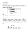
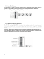
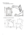
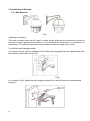
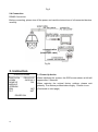
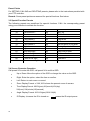
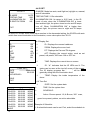
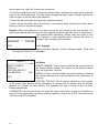
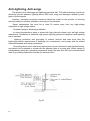
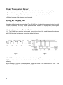
INSTALLATION MANUAL ST-PTZIR650-23 High Speed Intelligent Dome PTZ Color Camera Copyright North American Cable Equipment, WARNINGS AND CAUTIONS WARNING TO REDUCE THE RISK OF FIRE OR ELECTRIC SHOCK, DO NOT EXPOSE THIS PRODUCT TO RAIN OR MOISTURE. DO NOT INSERT ANY METALLIC OBJECTS THROUGH VENTILATION GRILLS OR OPENINGS ON THE EQUIPMENT. CAUTION EXPLANATION OF GRAPHICAL SYMBOLS The lighting flash with arrowhead symbol, within an equilateral triangle, is intended to alert the user the presence of non-insulated “dangerous voltage” within the product’s enclosure that maybe of sufficient magnitude to constitute a risk of electric shock to different persons. The exclamation point within an equilateral triangle, is intended to alert the user the presence of important operating and maintenance (servicing) instructions in the literature accompanying this product. PRECAUTIONS: Persons without technical qualifications should not attempt to operate this dome device before reading this manual thoroughly. Remove any power to the dome before attempting any operations or adjustments inside the dome cover to avoid potential damage to the mechanism. Inside the dome cover there are precision optical and electrical devices. Heavy pressure, shock and other sudden adjustments or operations should be avoided. Otherwise, you may cause irreparable damage to the product. Please DO NOT remove or disassemble any internal parts of the video camera to Avoid normal operation and possibly void the warranty. There are no serviceable parts inside the camera. All electrical connections to the dome should be made in strict accordance with the attached labels and wiring instructions in this manual and in accordance with all local and national electrical codes. Failure to do so may damage the dome beyond repair and void the warranty. For outdoor installation especially in high places or poles, it is highly recommended that the proper lightning arrestors and surge suppressors are installed before the dome is entered into service. Please do not use the product under circumstances where the environment exceeds the maximum specified temperature, humidity or power supply specifications. IMPORTANT SAFEGUARDS 1. Read these instructions before attempting installation or operation of this dome. 2. Keep these instructions for future reference. 3. Heed all warnings and adhere to electrical specifications. Follow all instructions. 4. Clean only with non abrasive dry cotton cloth, lint free and approved acrylic cleaners. 5. Should the clear dome of the camera become dirty, use a special lens cleaning cloth and solution to properly clean it. 6. Do not block any ventilation openings. Install in accordance with manufacturer’s instructions. 7. Use only attachments or accessories specified by the manufacturer. 8. Verify that the surface you are planning to use for attaching the dome can adequately support the weight of the device and mounting hardware. 9. Protect this device against lighting storms with proper power supplies, surge arrestors and other protective precautions. 10. Refer all servicing to SecurityTronix service personnel. Servicing is required when the device has been damaged in any way, when liquid traces are present, or the presence of loose objects is evident or if the device does not function properly, or has received sever impact or has been dropped accidentally. 11. Do not use this product under circumstances exceeding specified temperature and humidity ratings. 12. Avoid pointing the camera directly to the sun or other extremely bright objects for prolonged period of time avoiding the risk of permanent damages to the imaging sensor. 13. The attached instructions are for use by qualified personnel only. To reduce the risks of electric shock, do not perform any servicing other than contained in the operating instructions unless you are qualified to do so. 14. During usage, the user should abide by all electrical safety standards and adhere to electrical specifications for the operation of the dome. The control cable for RS485 communications as well as the video signal cables should be isolated from high voltage equipment and high voltage cables. 15. Use supplied power supply transformer only. 1 1 Product Contents IR Speed dome 1pc Wall mount bracket 1pc Power supply 1pc Screws kit 1pc User manual 1pc 2 1.2 Specification Horizontal Rotation Speed Tilt Rotation Speed Horizontal Rotation Range Tilt Rotation Range Auto Flip Auto control IR LED A-B Scan A-B Scan Speed 360° Scan Speed Dwell Preset Preset Points Go to Preset Speed Guard Tours Guard Points per tour Pattern Scan Pattern Scan Record Home Pos Time PWR on Action Communication Protocol Communication Baud Rate Privacy Mask 3D Location Time Scheduling function Alarm Auto-tracking Operating Temperature Operating humidity Heater & Blower Power Lightning protection IR Illumination Distance Power Consumption Compatible camara LED Angle of Illumination 3 0.02°-200°/s 0.02°-100°/s 360° 93° Horizontal 180°, Vertical 90° PWM User programmable 1-64 levels setting available 1-64 levels setting available 5-60s interval 220 200°/s 4 groups Max.16 points, dwell time user selectable 4 pcs max.15 minutes or 512 commands 1-60mins available Memory as power off / Pattern / 360° scan / A-B scan / Preset cruise / Preset 1-8 / No action Pelco-D,Pelco-P RS485 Bus 1200/2400/4800/9600bps Not supported on this module supported Not supported on this module Optional Optional Outdoor: -10°F ~ +130°F ≤95% Non Condensing Auto temperature control 24VAC ≤3A transient voltage 6000V 375 ft ≤ 20W SONY,HITACHI, SAMSUNG etc. Ø22=6,Ø16=5 1.3 Performance Features PWM function. Intelligent IR illumination & power consumption is variable, dependent upon the zoom factor. 3D allocation. The pan and zoom functions are performed simultaneously for faster target acquisition. Supported Protocols. Pelco-D/P; Others on special request. 4 path patterns. Each path can record 512 different instructions or 900s of PTZ instructions. Manual speed control. At the lowest 0.02º/s speed, the dome provides very smooth operation . 4 guard groups. Up to 16 preset points can be assigned in each tour. Each of the 16 points can be adjusted independently for dwell time and travel speed. Optional IP module (built in provision). Built-in high density RTC clock supports time management function. Strong video processing ability supports auto-tracking and motion detecting alarm function. Park action. If the user does not operate the dome in a predetermined time, it will automatically run a preset guard group, trace memory group, pan scan etc. The dome can remember its current operation before being powered off and return to its previous operation after power is restored. Built-in fan and heater can control the temperature automatically. Heater operates below 32°F and fan operates above 104°F. Multiple languages for OSD menu, English, Spanish, Chinese etc. The response of IR illumination to ambient light can be adjustable. Accurate step motor control provides for stable running, precise location and sensitive response. 4 Metal body construction with an environmental rating of IP 66. Built-in 6000V anti-surge protection equipment. 1.4 Function Description Auto-adaptive to Protocol and Module The dome can auto-adapt to multiple protocols and many camera modules without changing the DIP switchs. 3D Allocation Allow the camera to operate both the pan and tilt simultaneously while recalling presets, for faster operation. Privacy Masking (Not available on this module) This feature allows the user to set certain areas of the image as un-viewable, such as manager’s computers, restrooms, etc. Pattern Records the user’s operation of the PTZ controls and plays them back exactly as they were originally performed. Rather than a tour, where the camera moves single point to single point, the movement of a pattern follows all the nuance of the operator’s input. This dome camera has 4 path patterns. Each path can record 512 different instructions or the longest 15mins of path operation, whichever is less. Zero Alignment The user can specify a pan-position point to be the camera’s “zero point”. When the dome is in use, preset drift can occur over time. If this happens, the zero-point can be used as a reference for the dome to reset its alignment. Auto Flip In the manual tracking mode, when a target goes directly beneath the dome, the dome will automatically rotate 180 degree in horizontal direction to maintain continuity of tracking. When the dome flips, the camera starts moving upward as long as you hold the joystick in the down position. Focus The auto focus feature enables the camera to focus automatically to maintain clear image. The user can also use manual focus when conditions require it, such as when there are near and far objects in the frame at the same time. Under the following conditions, the camera may not auto focus on the target: (1) The target is not in the center of the screen; (2) Attempting to view 2 subjects which are far and near at the same time; (3) The target is a brightly lit object, such as a neon lamp, etc.;. (4) The camera’s dome is covered with water droplets or dust; (5) Targets are moving quickly; (6) Large area targets without much detail, such as wall; (7) Targets which are too dark or faint. 5 BLC Back Light Compensation (Not available on this model) If a bright backlight is present, the target in the picture may appear dark or as a silhouette. The BLC function can enhance the target in the center of the picture; the dome uses the center of the picture to adjust the iris. If there is a bright light source outside this area which tends to wash out to white, the camera will adjust the iris so that the target in the sensitive area will be properly exposed. Iris Control The camera features automatic camera aperture (iris). The camera senses changes in ambient light and automatically adjusts the lens aperture to make the brightness of the output image stable. Ratio Speed Intelligent pan and tilt speed is variable dependent on the zoom factor. When zooming in, the speed will become slower and when zooming out, the speed will become faster. Pan Scan The dome continuously scans 360°clockwise at set speed in horizontal direction, under the condition that the pitch angle remains the same. While scanning, the operator can move the joystick to exit from the scanning mode. Preset Once the camera has been programmed with specific location presets, it can automatically move to the predefined positions when presets are called from a PTZ controller or DVR. Guard Tour Scan The dome runs a patrol according to the specific presets which the user has programmed, in the order they are set to run. A-B Scan The dome scans back and forth between 2 preset points ( A-B points) in both horizontal and vertical directions, according to the speed the user sets in the menu. Power Off Memory This feature allows the dome to resume its previous preset or status after power is restored. By the default setting, the dome supports power up memory, which improves reliability and avoids repeated settings of the previous parameters. Park Action If the dome is not operated within the user-set time, it will automatically run a specific mode (pan scan, A-B scan, park action, cruise, preserve action etc.). Multilanguage OSD Menu The language used for the on screen menu can be set to one of several available languages English, Spanish etc. 6 2 Installation 2.1 DIP Switch Settings 2.1.1 Preparation Before installation, make sure that the protocol, baud rate and address code used by the product is fully consistent with the control system. Corresponding DIP switch settings can be seen below. The access plate for the DIP switches is located just above the camera lens opening on the outside of the camera: NOTE: It is much easier to set the communication parameters using the on-screen menu rather than the DIP switches. See page 11 for details. 2.1.2 Address Settings DIP switch SW1 is used to set the address of the camera. It is an 8-bit switch. The number value of switch 1 = 1, switch 2 = 2, switch 3 = 4, switch 4 = 8, switch 5 = 16, switch 6 = 32, switch 7 = 64 and switch 8 = 128. The values of all switches which are in the ON position are added to determine the address. (See illustration below) As an example, if the 1st and 3rd switches are allocated to the ON position, the binary code is 00000101, so the corresponding address is 5 (sw1 = 1 + sw3 = 4). For complete, detailed settings please refer to the “Address Code Mapping Tables” on pages 25 and 26. 7 2.1.3 Baud Rate Settings The 4th and 5th “Function” (FUN) DIP Switches set the Baud rate. Factory-default setting is 2400bps. This is the baud rate which SecurityTronix recommends for most installations. Baud rates: 1200bps, 2400bps, 4800bps, 9600bps selectable 2.1.4 RS-485 Bus Matching Resistance The 8th DIP switch of FUN SW2 is to select the matching resistor. In order to prevent interference of the RS-485 communication signal and other signals, the parallel matching resistor is needed in the communication interface of the dome camera at the far end of the RS485 bus run. Use the 8th switch of the FUN switch group to connect the resistor the the RS485 bus ONLY IF THE CAMERA IS THE LAST CAMERA ON THE BUS. If there are multiple PTZ cameras on the RS485 bus, all others should not have a termination resistor applied. 8 2.2 Bracket Dimensions 2.2.1 Included Wall Mounted Bracket 2.2.2 Optional Corner Mounted Bracket 9 2.3 Installation of Brackets. 2.3.1 Wall Mounted Fig 1 Installation conditions: This wall mounted dome can be used on walls whose thickness and sturdiness should be enough to install expansion bolt outdoors, or be used with an electrical box or mounted to a stud indoors. The wall must be able to bear at least 4 times the weight of the dome. To install the wall hanging bracket: a. As shown in fig 2, use the installation holes of the wall hanging bracket as a pattern and mark the locations of the holes on the wall. Fig 2 b. As shown in fig 3, attach the wall hanging bracket to the wall with wire and cable passed through it. 10 Fig 3 2.4 Connection RS485 Connection Before connecting, please turn off the power and read the instructions of all connected devices carefully. Fig 24 3. Instruction 3.1 Power Up Action IR SPEED DOME PROTOCOL COMM DOME ID MODULE VERSION PAN TILT PELCO-D/P 2400.N.8.1 001 POWER ON 11 INIT INIT When initializing the system, the OSD screen shown at left will appear after 2 seconds. When restoring the original factory settings, please wait patiently. The restore process takes roughly 1 minute to run. (Continued on next page) IR SPEED DOME PROTOCOL COMM DOME ID MODULE VERSION PAN TILT PELCO-D/P 2400.N.8.1 001 This screen shows that the initialization of the pan/tilt motors has completed. . OVER OVER POWER ON IR SPEED DOME PROTOCOL COMM DOME ID MODULE VERSION PAN TILT PELCO-D/P 2400.N.8.1 001 BT-367 XXX OVER OVER Power up self-testing has completed. POWER ON 3.2 Basic Function Dome Operation Use the control joystick up, down, left or right key on the keyboard. Zoom Press ZOOM- button to zoom “out” for a wider field of view for close objects. Press ZOOM+ button to zoom “in” for a narrower field of view for distant objects. Focus Press FOCUS+ button to manually focus the camera on distant objects. Press FOCUS- button to manually focus the camera on close objects. Iris Manual IRIS control is not supported on this camera module 12 Preset Points For SETTING, CALLING and DELETING presets, please refer to the instructions provided with your PTZ controller. Remark: Some preset points are reserved for special functions. See below. 3.3 Special Function Presets The following presets are predefined for special functions. CALL the corresponding preset using your controller to activate the function: PREST 33 34 75 76 77 78 79 80 81 82 83 84 85 FUNCTION Pan scan180 º Reset Call Pattern 1 Call Pattern 2 Call Pattern 3 Call Pattern 4 Digital zoom on Digital zoom off Auto day/night Switch to night Switch to day Force on far light PRESET 86 87 88 89 91 92 93 94 95 96 97 98 FUNCTION BLC on BLC off Freeze on Freeze off A-B scan Set left point of A-B scan Set right point of A-B scan OSD menu Close OSD menu Open Call tour 3 Call tour 2 Call tour 1 Force on near light 99 Pan scan 3.4 Screen Character Operation Call preset 95 to enter the OSD, call preset 94 to exit the OSD. Up or Down: Move the option of the OSD or change the value on the OSD. Right: Enter the option, select the item or confirm. Left: Return to main menu or cancel Zoom Display Format: x XXX, XXX shows the present zoom of camera. Time DisplayFormat: XXXX(year)-XX(month)-XX(day) XX(hour)-XX(minute)-XX(second) 13 Angle Display Format: XXX.XX(pan)/XXX.XX(tilt) IR Display: ☀means the IR is turned on. means the IR output power. 4 OSD Menu 4.1 Menu Index 14 4.1 System Information SYSTEM INFORMATION <MAIN MENU> <SYSTEM INFORMATION> <DOME SET> <CAM SET> <IR SET> <DISPLAY SET> <TIME SET> <LANGUAGE> <RESET> EXIT <SYSTEM INFORMATION> PROTOCOL PELCO-D/P BAUD RATE 2400.N.8.1 DOME ID 001 MODULE VERSION MAX SPEED 300 <SOFT ID SET> <PASSWORD SET> CANCEL <SOFT ID SET> CANCELID DEVICE CHECK ID TARGET ID BAUDE RATE SAVE EXIT PROTOCOL: Displays the protocol of the dome. Baud rate: represents the communication Information; 2400 is the baud rate, which can be changed via the DIP switches or software the available baud rates are: 1200, 2400, 4800 and 9600. “N.8.1” represents the Check bit, Data bit and Start bit. DOME ID: This is the address number of the dome. The range is 000-255. MODULE: Displays the brand and model of the installed camera module. VERSION: Displays the current operating system <SOFT ID SET> DEVICE ID: Used to distinguish this dome from the ID of other domes. CHECK ID: Enter the device ID above into this field to enable address changes for just this camera. TARGET ID: Enter the new address you wish to assign to this camera. It will be effective immediately after it is changed. <PASSWORD SET> PASSWORD 1: Enter the password, PASSWORD 2: Re-enter the password 4.2 Dome Set 4.2.1 Preset <PRESET> PRESET NO CALL PRESET <SET PRESET> EXIT 001 PRESET NO: Select the preset number to be SET or CALLED. CALL PRESET: Calls the preset number selected above. <SET PRESET: Writes the current camera position into the preset location entered above. 15 To write the preset, enter the command on your PTZ <PRESET> PRESET NO controller for “Call preset 1”. To cancel the write 001 CALL PRESET operation, enter the command on your PTZ <SET PRESET> controller for “Call preset 2”. PRESET 1: SAVE Because some presets are used to operate special functions, they can’t be set and called normally. PRESET 2: BACK 4.2.2 Scan <SCAN> SCAN SPEED <A POINT SET> <B POINT SET> CALL AB SCAN CALL 360 SCAN EXIT SCAN SPEED: Scan speed includes setting the A-B scan and 360°scan. speed of A&B POINT SET: The effective scan range of the A&B point boundaries is 20-340°. 4.2.3 Guard Tour CANCEL <GUARD TOUR> GUARD TOUR ID CALL GUARD TOUR <SET GUARD TOUR > The camera can save 4 guard tours. 1 Each tour has 16 points (presets) and each point can have its own dwell time and speed. GUARD TOUR ID: Choose tour 1 thru 4. EXIT <GUARD TOUR> ID POINT TIME SPEED 01 01 05 64 02 02 05 64 03 03 05 64 04 04 05 64 05 05 05 64 06 06 05 64 07 07 05 64 08 08 05 64 PAGING <GUARD TOUR> ID POINT TIME SPEED 09 09 05 64 10 10 05 64 11 11 05 64 12 12 05 64 13 13 05 64 14 14 05 64 15 15 05 64 16 16 05 64 SAVE 16 CALL GUARD TOUR: Calls the guard tour. <SET GUARD TOUR> ID: These are the 16 steps available for the tour. Each step will call 1 preset. POINT: The preset for each step. Any preset from 1 thru 64 can be assigned to a step. TIME: The default time of all points is 05s. The range is 05-60s. SPEED: The speed between two points in each guard tour group can be set individually. The range is 1-64. Note: Preset 33 and 34 can’t be set as guard tour point. 4.2.4 Pattern PATTERN ID: Factory default is 1. Select the pattern to be edited. There are 4 patterns. <PATTERN> PATTERN ID CALL PATTERN <PATTERN SET> 1 EXIT <PATTERN> PATTERN ID CALL PATTERN <PATTERN SET> CALL PATTERN: Call (run) the pattern which is currently selected. <PATTERN SET> The figure at left shows the screen when the camera is ready to record a pattern. 1 XXX/512 PRESET 1: SAVE PRESET 2: BACK “XXX” is the quantity of operator’s instructions used so far. The maximum amount of instructions available to record is 512. Remark: The precision of pattern is associated with the system settings and module of the camera. When using the pattern, it is recommended to turn off the privacy zone and unnecessary display function. 4.2.5 Privacy Zone (Unused on this model camera) MASK NO.: Select the mask number. It <DOME SET> <PRESET> <SCAN> <GUARD TOUR> <PATTERN> <PRIVACY ZONE> <OTHER> <ALARM > EXIT depends on the module supported. SET MASK: For detailed steps, please refer to the “Example of Setting Mask 1”. MASK: ON and OFF are selectable. Example of Setting Mask 1 1: Move the cursor to MASK NO, which is be selected by pressing the “right key”. 2: Press the “up and down” keys in the keyboard to edit the <PRIVACY ZONE> MASK NO 01 MASK <SET MASK> mask number, which is be entered by pressing the right key. “-” means selecting this mode, while “ ”, hourglass symbol, means editing this mode. 3: Move the cursor to <SET MASK> and press right key to set the position of privacy zone. See the figure on the left below. EXIT <PRIVACY ZONE> MASK NO 01 MASK ON <SET MASK> PRESET 1: SAVE PRESET 2: BACK 17 4: Move the joystick to aim at the object. Use the ZONE WIDE and ZONE TELE keys in the keyboard to adjust the size of picture. And use iris OPEN and CLOSE keys to adjust the size of mask. Call preset 1 to save and exit and call preset 2 to exit directly. Remark: The mask size is better more than double the target size. Setting the mask is associated with the pitch angle which is advised to be equal to or less than 45°. 4.2.6 Other HOME POS: There are 13 possible actions: preset 1-8, A-B scan, 360° scan, guard tour preset, pattern, no action. <DOME SET> <PRESET> <SCAN> <GUARD TOUR> <PATTERN> <PRIVACY ZONE> <OTHER> <ALARM > EXIT <OTHER> HOME POS NONE HOME TIME 05 POWER UP ACT RESTORE FLIP ON SPEED RATIO ON HOME TIME: The dome camera runs home position after a period of idle time. The range is 1-60 minutes. POWER UP ACT: There are 14 possible actions: preset 1-8, A-B scan, 360° scan, guard tour preset, pattern, power up restore, no action selectable. FLIP: When panning straight down – such as to follow a subject under the camera – the camera will spin 180 degrees and continue to tilt up after the spin.. SPEED RATIO: Ratio speed can be set ON or OFF. When SPEED RATIO is ON, the camera will pan slower when zoomed in. When this is OFF, the camera will always pan at the same maximum speed. EXIT 4.2.7 Alarm (Not used in this model camera) <DOME SET> <PRESET> <SCAN> <GUARD TOUR> <PATTERN> <PRIVACY ZONE> <OTHER> <ALARM > ALARM NO: 1-4 selectable. ALARM MODE: Mode has on an off selectable. PRIOR: Prior has none and 1-4 level selectable ALARM IN: Alarm in has low input and high input selectable. ALARM ACT: When prior is none, alarm action preset point 1-8 selectable, when prior is 1-4 level, alarm action has pattern, guard tour, 360 scan, preset scan and preset point 1-8 selectable. EXIT <ALARM SET> ALARM NO ALARM MODE PRIOR ALARM IN ALARM ACT ALARM OUT DWELL TIME PATROL TIME EXIT 18 1 ON BY TURN LOW INPUT NONE OFF OFF 6 ALARM OUT: Alarm out has nc and no selectable. DWELL TIME: Time has 0-59 second, 0-59minute and off selectable PATROL TIME: Patrol time 0-9s selectable. Note: If there are several alarm inputs at the same time, the system will respond to the alarm inputs by the dwell time. 4.4 IR SET <IR SET> IR MODE TESTING TIME ILLUMINATION ON IR SWITCH ZOOM IR MODE: Mode has auto, small light on, big light on, manual, and off selectable AUTO 08S 05L 04L TESTING TIME: 2-15s selectable ILLUMINATION ON: Its range is 0-25 level. In the IR mode of auto, when the “ILLUMINATION ON” is lower than ambient light, the picture turns to color and IR lamps turn off. When “ILLUMINATION ON” is higher than ambient light, the picture turns to night and IR lamps open. EXIT IR SWITCH ZOOM: When zoom value reaches to the demanded setting, the IR LEDs with auto switch from near illumination to far illumination, zoom value option from 01-23. <DISPLAY SET> ID ZOOM P/T ACT TIME IR TEMP EXIT 4.5 Display Set ON ON ON ON OFF ON ON ID : Displays the camera’s address. ZOOM: Displays the zoom level. P/T: Displays the Pan and Tilt degrees. ACT: Displays the current action, such as set preset, call preset, 360°scan. ON or OFF etc. TIME: Displays the current time on screen. IR: “☀” indicates that the IR LEDs are lit. The CANCEL <TIME SET> DATE 2000-01-01 TIME 00:00:00 <SCHEDULE> status can be seen at the top left corner of the screen. The IR display progress bar “ ” will be filled gradually along with the illumination level. SAVE EXIT 4.6 Time Set <SCHEDULE> START END ACT 00:00:00 00:00:00 NONE 00:00:00 00:00:00 NONE 00:00:00 00:00:00 NONE 00:00:00 00:00:00 NONE 00:00:00 00:00:00 NONE 00:00:00 00:00:00 NONE 00:00:00 00:00:00 NONE 00:00:00 00:00:00 NONE SAVE 19 TEMP: Display the inside temperature of the dome. DATE: Set the system date. TIME: Set the system time. SCHEDULE: Action: Choose preset 1-8, A-B scan, 360°scan, guard tour preset, pattern, no action selectable. Example of Schedule: 1: 8 scheduled events can be set. First, select the schedule to set and press the ‘right’ key to enter the edit screen. 2: Use the up and down keys to adjust the present value, and press the right key to enter and move to the next adjustment. The item being changed will blink. When it blinks, operate the right key again to exit the editing the schedule. 3: Select the next schedule and repeat the operations above. 4: When setting the status, press the left key to exit setting. When selecting the status, press left key to return to the previous page. Remark: When the schedule is set, there cannot be any overlap in the time periods. The system will respond with priority to the first triggered schedule, only after which is completed, it will respond other schedules. Please make sure there is only one schedule at each specific period. System will return to <LANGUAGE> preset 1 after completing the schedule. LANGUAGE ENGLISH 4.7 Language EXIT LANGUAGE: Language has English, Spanish, French, Germany, Italian, Polish and Portuguese, Russian etc. selectable. <RESET> RESET CAMERA DEFAULT FACTORY DEFAULT CALIBRATION EXIT 4.8 Reset RESET CAMERA: This is used to initialize the camera back to the factory default settings This applies to the camera module only, not to presets, tours etc.. OFF DEFAULT: This is used to initialize the system settings, including the camera settings, but it will not delete all the information in memory. FACTORY DEFAULT: This is used to initialize all of the settings of the system and camera. All the information in memory will be deleted, such as presets, patterns, etc. Please use this carefully. This operation will take a minute or more to finish. Please wait patiently. CALIBRATION: Execute this function to make the motor of the dome to reset in a fixed time to prevent locate inaccurately caused by external operation. Default set is OFF, the function has 1-59 days and OFF selectable. 20 Anti-lightning, Anti-surge This product is air discharge and lightning protected with TVS tube technology, which can effectively prevent transient lightning below 3000 volts, surge and damages caused by other types of pulse signals. However, necessary protective measures should be made on the premise of ensuring electrical safety for outdoor installation according to the situation : ·Signal transmission line must be at least 50 meters away from any high-voltage equipment or high voltage cables. · Overhead wiring is absolutely prohibited. · In strong thunderstorm areas or areas with high induced voltage (such as high voltage substations), installation of additional high power lightning protection equipment and lightning rod is essential. · Lightning protection and grounding of outdoor devices and lines must take the lightning-protection requirements of buildings into consideration, and comply with the related national standards and industry standards. · Grounding device must meet dual requirements of anti-interference and electrical safety, and should not be shorted or mixed with the adjacent lines in a power grid. When system is independently grounded, grounding impedance should be less than 4Ω, and cross-sectional area of grounding conductors must be not less than 25m2. Fig 25 21 Clean Transparent Cover In order to assure a clear image of dome, the clear dome should be cleaned regularly. ● Be careful when cleaning and hold the outer ring to avoid directly touching the dome. ● Please use a soft dry cloth or other alternatives to wipe internal and external surfaces. ● If dirt is heavy, a mild detergent may be used. Using an RS-485 Bus 1. Basic Feature of RS-485bus According to the industry bus standard, The RS-485 bus is half-duplex communication bus with a typical impedance of 120Ω, whose maximum load capacity is 32 payloads (including the master device and the controlled device). 2. Mode of Connection and Terminal Resistance 2.1 The RS485 bus requires that parallel connections should be used between the devices with 120Ω terminal resistances connected at the both ends. Fig 26 2.2 Fig 27 120Ω terminal resistance is connected as shown in fig 27. 120Ω terminal resistance is available in the circuit board and the connection is shown as following: When needing to connect 120Ω resistance, toggle the 8 th bit of DIP switch SW2 to "ON" . This will connect the 120Ω resistance to the circuit. 22 Address Code Mapping Table SW1 DIP Switch sets the dome address.. The following is a dome address code mapping table to set PELCO_D: Switch Settings Address 0 1 2 3 4 5 6 7 8 9 10 11 12 13 14 15 16 17 18 19 20 21 22 23 24 25 --250 251 252 253 254 255 23 SW1-1 OFF ON OFF ON OFF ON OFF ON OFF ON OFF ON OFF ON OFF ON OFF ON OFF ON OFF ON OFF ON OFF ON ---ON ON OFF ON OFF ON SW1-2 OFF OFF ON ON OFF OFF ON ON OFF OFF ON ON OFF OFF ON ON OFF OFF ON ON OFF OFF ON ON OFF OFF ---OFF ON OFF OFF ON ON SW1-3 OFF OFF OFF OFF ON ON ON ON OFF OFF OFF OFF ON ON ON ON OFF OFF OFF OFF ON ON ON ON OFF OFF ---ON OFF ON ON ON ON SW1-4 OFF OFF OFF OFF OFF OFF OFF OFF ON ON ON ON ON ON ON ON OFF OFF OFF OFF OFF OFF OFF OFF ON ON ---OFF ON ON ON ON ON SW1-5 OFF OFF OFF OFF OFF OFF OFF OFF OFF OFF OFF OFF OFF OFF OFF OFF ON ON ON ON ON ON ON ON ON ON ---ON ON ON ON ON ON SW1-6 OFF OFF OFF OFF OFF OFF OFF OFF OFF OFF OFF OFF OFF OFF OFF OFF OFF OFF OFF OFF OFF OFF OFF OFF OFF OFF ---ON ON ON ON ON ON SW1-7 OFF OFF OFF OFF OFF OFF OFF OFF OFF OFF OFF OFF OFF OFF OFF OFF OFF OFF OFF OFF OFF OFF OFF OFF OFF OFF ---ON ON ON ON ON ON SW1-8 OFF OFF OFF OFF OFF OFF OFF OFF OFF OFF OFF OFF OFF OFF OFF OFF OFF OFF OFF OFF OFF OFF OFF OFF OFF OFF ---ON ON ON ON ON ON The following is a dome address code mapping table to set PELCO_P: Switch Settings Address 1 2 3 4 5 6 7 8 9 10 11 12 13 14 15 16 17 18 19 20 21 22 23 24 25 26 --251 252 253 254 255 256 24 SW1-1 SW1-2 SW1-3 SW1-4 SW1-5 SW1-6 SW1-7 SW1-8 OFF ON OFF ON OFF ON OFF ON OFF ON OFF ON OFF ON OFF ON OFF ON OFF ON OFF ON OFF ON OFF ON ---ON ON OFF ON OFF ON OFF OFF ON ON OFF OFF ON ON OFF OFF ON ON OFF OFF ON ON OFF OFF ON ON OFF OFF ON ON OFF OFF ---OFF ON OFF OFF ON ON OFF OFF OFF OFF ON ON ON ON OFF OFF OFF OFF ON ON ON ON OFF OFF OFF OFF ON ON ON ON OFF OFF ---ON OFF ON ON ON ON OFF OFF OFF OFF OFF OFF OFF OFF ON ON ON ON ON ON ON ON OFF OFF OFF OFF OFF OFF OFF OFF ON ON ---OFF ON ON ON ON ON OFF OFF OFF OFF OFF OFF OFF OFF OFF OFF OFF OFF OFF OFF OFF OFF ON ON ON ON ON ON ON ON ON ON ---ON ON ON ON ON ON OFF OFF OFF OFF OFF OFF OFF OFF OFF OFF OFF OFF OFF OFF OFF OFF OFF OFF OFF OFF OFF OFF OFF OFF OFF OFF ---ON ON ON ON ON ON OFF OFF OFF OFF OFF OFF OFF OFF OFF OFF OFF OFF OFF OFF OFF OFF OFF OFF OFF OFF OFF OFF OFF OFF OFF OFF ---ON ON ON ON ON ON OFF OFF OFF OFF OFF OFF OFF OFF OFF OFF OFF OFF OFF OFF OFF OFF OFF OFF OFF OFF OFF OFF OFF OFF OFF OFF ---ON ON ON ON ON ON TROUBLESHOOTING a. No picture after applying power – (i) check all plugs and cables are connected to the proper connectors: (ii) ensure your power supply is providing the correct voltage and enough current. b. The picture has ripples – (i) Check to see if the power supply is experiencing AC ripple. If so, a filter may be required. (ii) Determine if the monitor is faulty. (iii) Determine if other peripheral equipment is causing the ripple and if so make the necessary adjustments. c. The picture background continuously changes color – A fluorescent lamp’s magnetic field may cause color roll. If possible, increase the distance between the camera and any fluorescent lamps in the vicinity. d. The picture appears smeared – (i) The power supply voltage level may be unstable. Try another power supply. (ii) Ensure the cables are correctly connected and of the right impedance. e. Other interference may require the use of a SecurityTronix ground loop isolation filter. f. Power is on but the controller does not work – (i) Check to make sure the DIP switches are all set correctly for address, baud rate and protocol. (ii) Check that the RS485 wires at the camera and controller have correct polarities. The camera colors are: Yellow = A (+), Orange = B (-). (iii) Check the integrity and continuity of the Unshielded Twisted Pair (UTP) cable. Additional troubleshooting assistance can be found online at www.securitytronix.com or email us at [email protected] or call (800) 688-9282 – Press “3” for tech support then “2” for SecurityTronix.. 25