1
Embedded Solutions
20G214-00 E1 – 2011-12-16
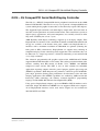
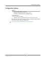
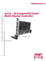
G214 – 3U CompactPCI Serial
Multi-Display Controller
Configuration example
(shown without heat sink)
User Manual
®
G214 – 3U CompactPCI Serial Multi-Display Controller
G214 – 3U CompactPCI Serial Multi-Display Controller
The G214 is a 4HP/3U CompactPCI® Serial peripheral board based on the AMD
Radeon™ E6760 GPU. The board is an easy way to provide a CompactPCI® Serial
system with high-end graphics features that are not offered by regular CPU chipsets.
The supported high resolutions and multi-display output make the board ideal to
meet the visual requirements of central control rooms, video surveillance systems or
digital signage applications. All board components are carefully selected to offer
long-term availability for at least 7 years.
AMD Eyefinity multi-display technology supports up to 6 display outputs: Four
DisplayPort® 1.2 interfaces with a maximum resolution of 4096x2560 at 60 Hz and
24 bpp are available at the board's front panel, another two DisplayPort® 1.1a
interfaces with a maximum resolution of 2560x1600 are optional (widening the
front panel to 8HP). Alternatively, DisplayPort® 1.2 supports daisy chaining of
compatible displays. If the connected panels support the same resolutions, they can
be addressed as a "single large surface", effectively functioning as one monitor with
a very large resolution.
The advanced, programmable 3D graphics engine of the AMD Radeon™ E6760
supports Microsoft® DirectX® 11 and comes with a third generation unified video
decoder, enabling dual HD decode of H.264, VC-1, MPEG4 and MPEG2
compressed video streams. The GPU is also an ideal solution for embedded
applications requiring compute intensive general purpose graphics processing unit
(GPGPU) capabilities. With 480 processing elements, it delivers up to 576 GFLOPs
peak single precision floating point performance for ultrasound, radar and video
imaging applications. The GPGPU capabilities are enabled by AMD Accelerated
Processing (APP) technology, the industry standard OpenCL™ programming
language and the AMD APP Software Development Kit (SDK).
Using passive DisplayPort® adapters, up to two HDMI or DVI-D monitors can be
connected. Single-link DVI-D and HDMI 1.4a are supported. With active adapters,
all six DisplayPort® interfaces can be used. Active adapters are also available for
dual-link DVI-D and VGA.
MEN Mikro Elektronik GmbH
20G214-00 E1 – 2011-12-16
2
Technical Data
Technical Data
Graphics
• AMD Radeon™ E6760 graphics processor
- 600 MHz max. graphics engine operating frequency
• 6 SIMD engines x 80 processing elements = 480 shaders
• Floating Point Performance (single precision, peak): 576 GFLOPS
• Display Engine: AMD EyeSpeed visual acceleration, AMD Eyefinity, AMD
HD3D technologies
• DirectX® 11
• Shader Model 5.0
• OpenGL® 4.1
• OpenCL™ compliant: AMD APP, OpenCL™ 1.1, DirectCompute 11
• Unified Video Decoder 3 for H.264, VC-1, MPEG-2, MPEG-4 part 2 decode
Memory
• 128-bit wide, 1 GB, GDDR5
• Operating frequency: 800 MHz / 3.2 Gbps
Front Connections (Standard)
• 4 DisplayPort® 1.2 interfaces
- Maximum resolution: 4096x2560 pixels at 24 bpp / 60 Hz
Miscellaneous
• Temperature sensor
• Reset via CompactPCI® Serial connector
CompactPCI® Serial
• Compliance with CompactPCI® Serial PICMG CPCI-S.0 Specification
• Peripheral slot
• Host interface: 4 or 8 PCI Express® lanes
Electrical Specifications
• Supply voltage/power consumption:
- +12 V (9..16 V), 35 W max.
Mechanical Specifications
• Dimensions: conforming to CompactPCI® Serial specification for 3U boards
• Front panel: 4 HP with ejector
• Weight: approx. 260 g (with heat sink)
MEN Mikro Elektronik GmbH
20G214-00 E1 – 2011-12-16
3
Technical Data
Environmental Specifications
• Temperature range (operation):
- 0..+60°C
- Airflow: min. 1.0 m/s
• Temperature range (storage): -40..+85°C
• Relative humidity (operation): max. 95% non-condensing
• Relative humidity (storage): max. 95% non-condensing
• Altitude: -300 m to +3,000 m
• Shock: 50 m/s², 30 ms
• Vibration (function): 1 m/s², 5 Hz – 150 Hz
• Vibration (lifetime): 7.9 m/s², 5 Hz – 150 Hz
• Conformal coating on request
MTBF
• 150,000+ h (tbc.) @ 40°C according to IEC/TR 62380 (RDF 2000)
Safety
• PCB manufactured with a flammability rating of 94V-0 by UL recognized manufacturers
EMC
• Conforming to EN 55022 (radio disturbance), IEC 61000-4-2 (ESD), IEC
61000-4-3 (electromagnetic field immunity), IEC 61000-4-4 (burst), IEC 610004-5 (surge) and IEC 61000-4-6 (conducted disturbances)
Electrical Safety Standards
• Conforming to EN 50155 (insulation measurement 10.2.9.1, voltage withstand
10.2.9.2), EN 60950 (information technology equipment), EN 50124-1 (Annex
B) (voltage withstand)
Software Support
•
•
•
•
Windows® Vista™
Windows® 7
Linux
For more information on supported operating system versions and drivers see
online data sheet.
MEN Mikro Elektronik GmbH
20G214-00 E1 – 2011-12-16
4
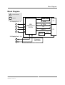
Block Diagram
Block Diagram
F
Front connector
SPI
Options
4x DisplayPort 1.2
F
F
Serial Flash
P2
x4 PCIe
x4 PCIe
GPU
(AMD Radeon
E6760)
I2C
F
RESET
P1
F
DC/DC
+12V
2x DisplayPort 1.1a
F
F
MEN Mikro Elektronik GmbH
20G214-00 E1 – 2011-12-16
Extension
side board
5
Configuration Options
Configuration Options
Graphics
• 2 additional DisplayPort® 1.1a interfaces
- Maximum resolution 2560x1600 at 24 bpp / 60 Hz
- Available via standard connectors on 8HP front panel
CompactPCI Serial
• Only P1 connector assembled
- When more than a x4 PCIe® connection is not required / not possible
Please note that some of these options may only be available for large volumes.
Please ask our sales staff for more information.
For available standard configurations see online data sheet.
MEN Mikro Elektronik GmbH
20G214-00 E1 – 2011-12-16
6
Product Safety
Product Safety
!
Electrostatic Discharge (ESD)
Computer boards and components contain electrostatic sensitive devices.
Electrostatic discharge (ESD) can damage components. To protect the board and
other components against damage from static electricity, you should follow some
precautions whenever you work on your computer.
• Power down and unplug your computer system when working on the inside.
• Hold components by the edges and try not to touch the IC chips, leads, or circuitry.
• Use a grounded wrist strap before handling computer components.
• Place components on a grounded antistatic pad or on the bag that came with the
component whenever the components are separated from the system.
• Store the board only in its original ESD-protected packaging. Retain the original
packaging in case you need to return the board to MEN for repair.
MEN Mikro Elektronik GmbH
20G214-00 E1 – 2011-12-16
7
About this Document
About this Document
This user manual describes the hardware functions of the board, connection of
peripheral devices and integration into a system. It also provides additional
information for special applications and configurations of the board.
The manual does not include detailed information on individual components (data
sheets etc.). A list of literature is given in the appendix.
History
Issue
E1
Comments
First issue
Date
2011-12-16
Conventions
!
italics
bold
monospace
This sign marks important notes or warnings concerning proper functionality of the
product described in this document. You should read them in any case.
Folder, file and function names are printed in italics.
Bold type is used for emphasis.
A monospaced font type is used for hexadecimal numbers, listings, C function
descriptions or wherever appropriate. Hexadecimal numbers are preceded by "0x".
comment
Comments embedded into coding examples are shown in green color.
hyperlink
Hyperlinks are printed in blue color.
The globe will show you where hyperlinks lead directly to the Internet, so you can
look for the latest information online.
IRQ#
/IRQ
Signal names followed by "#" or preceded by a slash ("/") indicate that this signal is
either active low or that it becomes active at a falling edge.
in/out
Signal directions in signal mnemonics tables generally refer to the corresponding
board or component, "in" meaning "to the board or component", "out" meaning
"coming from it".
Vertical lines on the outer margin signal technical changes to the previous issue of
the document.
MEN Mikro Elektronik GmbH
20G214-00 E1 – 2011-12-16
8
About this Document
Legal Information
MEN Mikro Elektronik GmbH ("MEN") reserves the right to make changes without further notice to any products herein.
MEN makes no warranty, representation or guarantee of any kind regarding the suitability of its products for any particular
purpose, nor does MEN assume any liability arising out of the application or use of any product or circuit, and specifically
disclaims any and all liability, including, without limitation, consequential or incidental damages. TO THE EXTENT
APPLICABLE, SPECIFICALLY EXCLUDED ARE ANY IMPLIED WARRANTIES ARISING BY OPERATION OF LAW,
CUSTOM OR USAGE, INCLUDING WITHOUT LIMITATION, THE IMPLIED WARRANTIES OF
MERCHANTABILITY AND FITNESS FOR A PARTICULAR PURPOSE OR USE. In no event shall MEN be liable for
more than the contract price for the products in question. If buyer does not notify MEN in writing within the foregoing
warranty period, MEN shall have no liability or obligation to buyer hereunder.
The publication is provided on the terms and understanding that:
1. MEN is not responsible for the results of any actions taken on the basis of information in the publication, nor for any error in
or omission from the publication; and
2. MEN is not engaged in rendering technical or other advice or services.
MEN expressly disclaims all and any liability and responsibility to any person, whether a reader of the publication or not, in
respect of anything, and of the consequences of anything, done or omitted to be done by any such person in reliance, whether
wholly or partially, on the whole or any part of the contents of the publication.
The correct function of MEN products in mission-critical and life-critical applications is limited to the environmental
specification given for each product in the technical user manual. The correct function of MEN products under extended
environmental conditions is limited to the individual requirement specification and subsequent validation documents for each
product for the applicable use case and has to be agreed upon in writing by MEN and the customer. Should the customer
purchase or use MEN products for any unintended or unauthorized application, the customer shall indemnify and hold MEN
and its officers, employees, subsidiaries, affiliates, and distributors harmless against all claims, costs, damages, and expenses,
and reasonable attorney fees arising out of, directly or indirectly, any claim or personal injury or death associated with such
unintended or unauthorized use, even if such claim alleges that MEN was negligent regarding the design or manufacture of the
part. In no case is MEN liable for the correct function of the technical installation where MEN products are a part of.
All products or services mentioned in this publication are identified by the trademarks, service marks, or product names as
designated by the companies who market those products. The trademarks and registered trademarks are held by the companies
producing them. Inquiries concerning such trademarks should be made directly to those companies.
Copyright © 2011 MEN Mikro Elektronik GmbH. All rights reserved.
Please recycle
Germany
MEN Mikro Elektronik GmbH
Neuwieder Straße 3-7
90411 Nuremberg
Phone +49-911-99 33 5-0
Fax +49-911-99 33 5-901
E-mail [email protected]
www.men.de
MEN Mikro Elektronik GmbH
20G214-00 E1 – 2011-12-16
France
MEN Mikro Elektronik SA
18, rue René Cassin
ZA de la Châtelaine
74240 Gaillard
Phone +33 (0) 450-955-312
Fax +33 (0) 450-955-211
E-mail [email protected]
www.men-france.fr
USA
MEN Micro, Inc.
24 North Main Street
Ambler, PA 19002
Phone (215) 542-9575
Fax (215) 542-9577
E-mail [email protected]
www.menmicro.com
9
Contents
Contents
1 Getting Started . . . . . . . . . . . . . . . . . . . . . . . . . . . . . . . . . . . . . . . . . . . . . . . .
1.1 Map of the Board. . . . . . . . . . . . . . . . . . . . . . . . . . . . . . . . . . . . . . . . .
1.2 Integrating the Board into a System . . . . . . . . . . . . . . . . . . . . . . . . . .
1.3 Installing Driver Software . . . . . . . . . . . . . . . . . . . . . . . . . . . . . . . . . .
11
11
12
12
2 Functional Description . . . . . . . . . . . . . . . . . . . . . . . . . . . . . . . . . . . . . . . . . .
2.1 Power Supply. . . . . . . . . . . . . . . . . . . . . . . . . . . . . . . . . . . . . . . . . . . .
2.2 Reset Behavior. . . . . . . . . . . . . . . . . . . . . . . . . . . . . . . . . . . . . . . . . . .
2.3 Thermal Considerations. . . . . . . . . . . . . . . . . . . . . . . . . . . . . . . . . . . .
2.4 Graphics. . . . . . . . . . . . . . . . . . . . . . . . . . . . . . . . . . . . . . . . . . . . . . . .
2.4.1
Display Port Interfaces . . . . . . . . . . . . . . . . . . . . . . . . . . . . .
2.4.2
Connecting Multiple Displays . . . . . . . . . . . . . . . . . . . . . . .
2.4.3
Daisy-Chaining Displays with DisplayPort 1.2 . . . . . . . . . .
2.5 AMD Eyefinity Multi-Display Technology. . . . . . . . . . . . . . . . . . . . .
2.6 Other Graphics Interfaces . . . . . . . . . . . . . . . . . . . . . . . . . . . . . . . . . .
2.7 PCI Express . . . . . . . . . . . . . . . . . . . . . . . . . . . . . . . . . . . . . . . . . . . . .
2.8 CompactPCI Serial . . . . . . . . . . . . . . . . . . . . . . . . . . . . . . . . . . . . . . .
13
13
13
13
13
13
14
15
15
16
16
16
3 Appendix . . . . . . . . . . . . . . . . . . . . . . . . . . . . . . . . . . . . . . . . . . . . . . . . . . . . . 17
3.1 Literature and Web Resources . . . . . . . . . . . . . . . . . . . . . . . . . . . . . . . 17
3.2 Finding out the Product’s Article Number,
Revision and Serial Number . . . . . . . . . . . . . . . . . . . . . . . . . . . . . . . . 17
Figures
Figure 1. Map of the board – top view. . . . . . . . . . . . . . . . . . . . . . . . . . . . . . . . . 11
Figure 2. Front panel - standard 4HP model and optional 8HP model . . . . . . . . 11
Figure 3. Labels giving the product’s article number,
revision and serial number . . . . . . . . . . . . . . . . . . . . . . . . . . . . . . . . . . 17
Tables
Table 1.
Table 2.
Table 3.
Table 4.
Table 5.
MEN Mikro Elektronik GmbH
20G214-00 E1 – 2011-12-16
Pin assignment of 20-pin DisplayPort connector . . . . . . . . . . . . . . . . .
Signal mnemonics of 20-pin DisplayPort connector . . . . . . . . . . . . . .
Maximum resolution with x8 PCI Express connection . . . . . . . . . . . .
Maximum resolution with x4 PCI Express connection . . . . . . . . . . . .
Maximum pixel rates at 5.4 GHz link rate (DisplayPort 1.2). . . . . . . .
13
14
14
15
15
10
Getting Started
1
Getting Started
This chapter gives an overview of the board and some hints for first installation in a
system.
1.1
Map of the Board
Figure 1. Map of the board – top view
DisplayPort
interfaces
1..4
APU
under heat sink
Side board
connector
for additional
DisplayPort
interfaces
5..6
P2
Heat sink
P1
Figure 2. Front panel - standard 4HP model and optional 8HP model
CompactPCI ®
Serial
CompactPCI ®
Serial
DP1
DP1
DP5
DP6
DP4
DP4
20G214-00 E1 – 2011-12-16
DP3
DP3
MEN Mikro Elektronik GmbH
DP2
DP2
G214
G214
11
Getting Started
1.2
Integrating the Board into a System
You can use the following check list when installing the board in a system for the
first time and with minimum configuration.
Power down the system.
Insert the G214 into a peripheral slot of your CompactPCI Serial system, making sure that the CompactPCI Serial connectors are properly aligned.
Note: The peripheral slots of every CompactPCI Serial system are marked by a
circle with a plus sign behind it on the backplane and/or at the front
panel.
Power up the system.
You can now install driver software for the G214 graphics controller.
1.3
Installing Driver Software
For a detailed description on how to install driver software please refer to the
respective documentation.
You can find any driver software available for download on MEN’s website.
MEN Mikro Elektronik GmbH
20G214-00 E1 – 2011-12-16
12
Functional Description
2
Functional Description
2.1
Power Supply
The G214 is supplied with +12V (-3%/+5%) via the CompactPCI Serial bus.
2.2
Reset Behavior
The G214 can be reset using the RST# signal on the backplane.
2.3
Thermal Considerations
A suitable heat sink is provided to meet thermal requirements.
!
Please note that if you use any other heat sink than that supplied by MEN, or no heat
sink at all, warranty on functionality and reliability of the G214 may cease. If you
have any questions or problems regarding thermal behavior, please contact MEN.
2.4
Graphics
The G214 is based on the AMD Radeon E6760 GPU (Graphics Processing Unit).
2.4.1
Display Port Interfaces
The standard G214 offers four DisplayPort 1.2 interfaces at the board’s 4HP front
panel. Two more DisplayPort 1.1a interfaces can be made available via an optional
side board, requiring a wider 8HP front panel for the additional connectors.
Connector types:
• 20-pin DisplayPort receptacle
• Mating connector:
20-pin DisplayPort plug
Table 1. Pin assignment of 20-pin DisplayPort connector
MEN Mikro Elektronik GmbH
20G214-00 E1 – 2011-12-16
20
POWER
19
RETURN PWR
18
HOTPLUG
17
AUX-
16
GND
15
AUX+
14
CONFIG2
13
CONFIG1
12
LANE_3-
11
GND
10
LANE_3+
9
LANE_2-
8
GND
7
LANE_2+
6
LANE_1-
5
GND
4
LANE_1+
3
LANE_0-
2
GND
1
LANE_0+
13
Functional Description
Table 2. Signal mnemonics of 20-pin DisplayPort connector
Signal
Direction
Function
GND
-
Ground
AUX-, AUX+
in/out
Bi-directional half-duplex auxiliary channels
for device management and device control
CONFIG1, CONFIG2 -
Connected to Ground
HOTPLUG
in
Hot Plug Detect
LANE_[3..0]+,
LANE_[3..0]-
out
Main Link data lanes
POWER
out
Power for connector (3.3 V, 500 mA)
RETURN PWR
-
Return for Power
2.4.2
Connecting Multiple Displays
The G214 supports can output a maximum of six independent images via its
DisplayPort connectors.
If more than one DisplayPort interface is used, the type of PCIe connection limits
the possible maximum resolutions. The following table shows the maximum
resolutions for one through six active DisplayPort interfaces. It shows the possible
resolution when every connected DisplayPort is used with the same resolution.
Note: Reducing the resolution of one DisplayPort can free resources to increase the
resolution of another DisplayPort.
Table 3. Maximum resolution with x8 PCI Express connection
Number of active
DisplayPort
interfaces
Color depth in bits per pixel at 60 Hz
18 bpp
24 bpp
30 bpp
1x DisplayPort 1.2
4096 x 2560
4096 x 2560
3840 x 2400
2x DisplayPort 1.2
4096 x 2560
4096 x 2560
3072 x 1920
3x DisplayPort 1.2
3072 x 1920
3072 x 1920
2560 x 1600
4x DisplayPort 1.2
3072 x 1920
2560 x 1600
2560 x 1600
With optional DisplayPort 1.1a interfaces
4x DisplayPort 1.2 +
1x DisplayPort 1.1
3072 x 1920
2560 x 1600
1920 x 1200
4x DisplayPort 1.2 +
2x DisplayPort 1.1
2560 x 1600
1920 x 1200
1920 x 1200
MEN Mikro Elektronik GmbH
20G214-00 E1 – 2011-12-16
14
Functional Description
Table 4. Maximum resolution with x4 PCI Express connection
Number of active
DisplayPort
interfaces
Color depth in bits per pixel at 60 Hz
18 bpp
24 bpp
30 bpp
1x DisplayPort 1.2
4096 x 2560
4096 x 2560
3840 x 2400
2x DisplayPort 1.2
3072 x 1920
2560 x 1600
2560 x 1600
3x DisplayPort 1.2
2560 x 1600
1920 x 1200
1920 x 1200
4x DisplayPort 1.2
1920 x 1200
1920 x 1200
1600 x 1200
With optional DisplayPort 1.1a interfaces
4x DisplayPort 1.2 +
1x DisplayPort 1.1
1920 x 1200
1600 x 1200
1280 x 720
4x DisplayPort 1.2 +
2x DisplayPort 1.1
1920 x 1200
1280 x 720
1280 x 720
2.4.3
Daisy-Chaining Displays with DisplayPort 1.2
DisplayPort 1.2 simplifies display connectivity with multi-streaming technology
(MST), enabling daisy-chaining of displays compatible with DisplayPort 1.2 and
the use of MST hubs to drive multiple displays via a single DisplayPort connector.
The resolution for each display connected via MST is limited by the maximum pixel
rate for a single link. The table below shows the maximum megapixels per second
for DisplayPort links using all four DisplayPort lanes.
Table 5. Maximum pixel rates at 5.4 GHz link rate (DisplayPort 1.2)
Color depth
in bits per pixel
18 bpp
24 bpp
30 bpp
Max. megapixel rate
957 MP/s
718 MP/s
574 MP/s
For example, a single DisplayPort 1.2 link can support two 2560x1600 displays at
60Hz and 30 bpp with one cable, or four displays at 1920x1200. With a color depth
of 24 bpp, up to six displays at 1600x1200 are possible.
Keep in mind that the G214 supports a maximum of six independent images and
that maxing out the throughput of one DisplayPort interface by connecting multiple
displays may require reducing the resolution or color depth of other interfaces.
2.5
AMD Eyefinity Multi-Display Technology
The G214 supports AMD Eyefinity technology, making it possible to address up to
six connected displays as a "single large surface", appearing as one very large screen
area to the application. For this, the output resolution for all displays must be
identical.
For further information on AMD Eyefinity technology and helpful hints for setting
up an Eyefinity multi-display system, please refer to the AMD website:
http://www.amd.com/eyefinity
MEN Mikro Elektronik GmbH
20G214-00 E1 – 2011-12-16
15
Functional Description
2.6
Other Graphics Interfaces
Many third-party suppliers offer adapters from DisplayPort to other graphics
interfaces. The maximum resolution depends on the adapter used. Supported
interfaces include:
•
•
•
•
HDMI
Single-link DVI
Dual-link DVI
VGA
Up to two passive adapters to DVI-D (single link) or HDMI are supported by the
G214. There is no limit to the number of active adapters used.
2.7
PCI Express
The G214 connects to the system’s CPU board via a PCI Express 2.1 interface.
Depending on the peripheral slot used, a x8 or x4 PCIe connection is established.
The supported data rates are up to 500 MB/s per lane, i.e., up to 4 GB/s with a fat
pipe connection (see Chapter 2.8 CompactPCI Serial for more information on
peripheral slot types).
2.8
CompactPCI Serial
The G214 is a CompactPCI Serial peripheral board. It uses one or two x4 PCI
Express links at the backplane according to the CompactPCI Serial specification
(PICMG CPCI-S.0). In standard CompactPCI Serial systems, the PCI Express x8
connection is only available when the board is installed in peripheral slots 1 and 2
(fat pipe). Slots 3 to 8 only allow for a x4 PCIe connection, the technical limitations
of which are detailed in Table 4, Maximum resolution with x4 PCI Express
connection on page 15. As an option, the G214 is also available with only the P1
connector assembled for cases when more than a x4 PCIe connection is not required
or not possible.
For the pin assignment and a detailed description of the signals refer to the
CompactPCI Serial specification.
MEN Mikro Elektronik GmbH
20G214-00 E1 – 2011-12-16
16
Appendix
3
Appendix
3.1
Literature and Web Resources
• G214 data sheet with up-to-date information and documentation:
www.men.de/products/02G214-.html
3.2
Finding out the Product’s Article Number, Revision and
Serial Number
MEN user documentation may describe several different models and/or design
revisions of the G214. You can find information on the article number, the design
revision and the serial number on a label attached to the board.
• Article number: Gives the product’s family and model. This is also MEN’s
ordering number. To be complete it must have 9 characters.
• Revision number: Gives the design revision of the product.
• Serial number: Unique identification assigned during production.
If you need support, you should communicate these numbers to MEN.
Figure 3. Labels giving the product’s article number, revision and serial number
Complete article number
*
Revision number
Serial number
MEN Mikro Elektronik GmbH
20G214-00 E1 – 2011-12-16
17