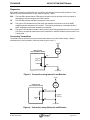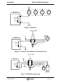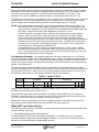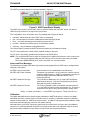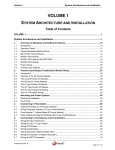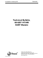
1
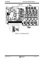
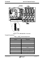
Last Updated: 04-January-2012 TB-090003B Technical Bulletin, 68-6207 HT/HM HART Module OMNI FLOW COMPUTERS, INC. 12620 West Airport Boulevard, Suite 100 Sugar Land, Texas 77478 United States of America Phone-281.240.6161 Fax: 281.240.6162 www.omniflow.com 52-0000-0019/Rev B Page 1 of 12 TB-090003B 68-6207 HT/HM HART Module NOTE: User Manual Reference - This Technical Bulletin complements the information contained in Volume 1, System Architecture and Installation for all firmware revisions. Table of Contents Scope ............................................................................................................................................3 Abstract .........................................................................................................................................3 Features and Specifications ......................................................................................................3 Installation .................................................................................................................................3 Terminal Connections ...............................................................................................................5 Diagnostics................................................................................................................................6 Connecting Transmitters ...........................................................................................................6 I/O Point Assignments (HART inputs) .......................................................................................8 I/O Point Assignments (Analog outputs) ...................................................................................8 Configuration .............................................................................................................................9 Transmitter Configuration..........................................................................................................9 OMNI HART Input Configuration...............................................................................................9 OMNI HART Input Status Display ...........................................................................................10 Alarms and Error Messages....................................................................................................11 Calibration ...............................................................................................................................11 Figures Figure 1. Figure 2. Figure 3. Figure 4. Figure 5. Figure 6. Figure 7. Figure 8. HT or HM Label Rev B ..................................................................................................4 HT or HM Label Rev C and Later..................................................................................5 Connection using Internal Load Resistor ......................................................................6 Connection using External Load Resistor .....................................................................6 Multi-Drop......................................................................................................................7 Connection using IS Barrier and Internal Load .............................................................7 MTL5042, Internal Load ................................................................................................7 HART Input Status Display .........................................................................................11 52-0000-0019/Rev B Page 2 of 12 TB-090003B 68-6207 HT/HM HART Module Scope This Technical Bulletin applies to all Revisions of the OMNI 6000/3000 Flow Computer running the following application firmware and OMNICOM Version: 20.75.01 and Higher with OMNICOM V1.42 and higher 22.75.02 and Higher with OMNICOM V1.43 and higher 23.75.01 and Higher with OMNICOM V1.44 and higher 24.75.01 and Higher with OMNICOM V1.42 and higher 26.75.03 and Higher with OMNICOM V1.40 and higher 27.75.04 and Higher with OMNICOM V1.41 and higher The application firmware applies to OMNI 3000/6000 Flow Computers equipped with the 68-6201 CPU board only. NOTE: Always install and run the latest copy of OMNICOM. Abstract OMNI Flow Computers manufactures an I/O Module and supporting firmware for the OMNI 3000/6000 Flow Computer that implement the HART Protocol. The model number for the HART module is: 68-6207 HT/HM HART Module Features and Specifications The 68-6207 HT/HM Module provides the following: Four (4) independent HART FSK networks Two (2) 4-20 mA Analog Outputs Maximum of four (4) modules per OMNI 3000/6000 Point-to-point transmitter connections use the (HT) option Multi-drop and multivariable transmitter connections use the (HM) option Four (4) devices per network in Multi-drop mode. The module is shipped as one (1) of two (2) optional types, a 68-6207-HT or a 68-6207-HM. The HT option is for use in point-to-point systems, while the HM option can be used in point-to-point, multi-drop, or multivariable mode systems. The type of the module is programmed at the factory and cannot be changed in the field. It is indicated by an “HT” or “HM” label as shown in Figures 1 and 2. There can be a maximum of six (6) installed 68-6207 Modules per OMNI 3000/6000 and these can be any combination of HT or HM modules. Each module must be configured for a unique address between one (1) and six (6) using jumpers on the module. The 68-6207 module and flow computer firmware support HART Protocol Revision 5 and above. Supported HART devices include: temperature, pressure and differential pressure transmitters. Installation The HART Module can be installed in any I/O slot but it is recommended that it be placed after other combo module types(s) installed in the chassis. Each HART module installed in the chassis must be configured for a unique address using the module address jumpers. It is recommended that HT modules be addressed first followed by any HM modules. Loop power must be provided externally using the OMNI 24 VDC terminals or an additional power supply. Loop load resistors are provided on the module for convenience and can be selected as being OUT of circuit, 250 ohms, or 500 ohms. When in the OUT position, a load resistor from 250 ohms to 600 ohms must be provided externally. 52-0000-0019/Rev B Page 3 of 12 TB-090003B 68-6207 HT/HM HART Module Figure 1. HT or HM Label Rev B 52-0000-0019/Rev B Page 4 of 12 TB-090003B 68-6207 HT/HM HART Module Figure 2. HT or HM Label Rev C and Later Terminal Connections Table 1. HART Terminal Assignments 68-6207 HART Terminal Assignments Terminal Assignment 1 Net 1+ 2 Net 1- 3 Net 2+ 4 Net 2- 5 Net 3+ 6 Net 3- 7 Net 4+ 8 Net 4- 9 Return (DC-) for Analog Out 1 &2 10 Return (DC-) for Analog Out 1 &2 11 Analog Out 1 12 Analog Out 2 52-0000-0019/Rev B Page 5 of 12 TB-090003B 68-6207 HT/HM HART Module Diagnostics Each HART Network is provided with four (4) LEDs to help diagnose communication problems. They indicate the communication traffic on each network (Figures 1 and 2). RTS This red LED indicates that the FSK carrier has been turned on and that the flow computer is attempting to send a message to the HART network. TX This red LED indicates that data is being sent to the network. CD This green LED indicates that an FSK carrier that satisfies the minimum level of the HART standard has been detected on the network. This may be generated by a transmitter and/or a HART handheld communicator attached to the network. RX This green LED indicates that data is being received and is being transferred to the flow computer. This may be a response transmission from a transmitter or a HART handheld communicator if one is being used. Connecting Transmitters Transmitters can be connected using the internal load resistor or an external load resistor. Multiple transmitters are wired in parallel in multi-drop mode (Figures 3 thru 7) +24VDC HART XMTR OMNI 68-6207 HART INTERFACE BOARD NET + 250 Ohm or 500 Ohm JUMPER NET - DC RETURN . Figure 3. Connection using Internal Load Resistor +24VDC HART XMTR OMNI 68-6207 HART INTERFACE BOARD NET + JUMPER OUT 250 Ohm to 600 Ohm NET - DC RETURN Figure 4. Connection using External Load Resistor 52-0000-0019/Rev B Page 6 of 12 TB-090003B 68-6207 HT/HM HART Module +24VDC HART XMTR OMNI 68-6207 HART INTERFACE BOARD HART XMTR HART XMTR HART XMTR NET + 250 Ohm or 500 Ohm JUMPER NET - DC RETURN Figure 5. Multi-Drop SAFE AREA HAZARDOUS AREA I.S. BARRIER +24VDC OMNI 68-6207 HART INTERFACE BOARD HART XMTR 1 NET + 2 MTL 3 7787+ 4 250 Ohm or 500 Ohm JUMPER NET - DC RETURN Figure 6. Connection using IS Barrier and Internal Load SAFE AREA +24VDC OMNI 68-6207 HART INTERFACE BOARD I.S. BARRIER 12 11 250 Ohm or 500 Ohm 13 NET - 5 14 NET + JUMPER HAZARDOUS AREA MTL 5042 4 2 1 DC RETURN HART XMTR HANDHELD COMMUNICATOR Figure 7. MTL5042, Internal Load 52-0000-0019/Rev B Page 7 of 12 TB-090003B 68-6207 HT/HM HART Module I/O Point Assignments (HART inputs) The OMNI 3000/6000 Flow Computer provides a set of 64 HART device I/O point assignments that range from 25 – 88. Each HT module is allocated four (4) I/O point assignments (one for each of the available HART networks). These are allocated before any HM module I/O point assignments. HT module I/O point assignments always start with input 25 and are assigned sequentially thereafter. I/O points of multiple HT modules are assigned in ascending order of their configured hardware addresses (i.e. HT-1, HT-2, HT-3 and finally HT-4). Each installed HM module is allocated sixteen (16) I/O point assignments. These are assigned after all HT module I/O assignments have been made. To accommodate up to four (4) multi-dropped devices on each HM network, four (4) I/O point assignments are allocated to each network. I/O points are assigned sequentially, starting with the first available assignment after the HT module assignments. I/O points for multiple HM modules are assigned in sequential order of their configured hardware addresses (i.e. HM-1, HM-2, HM-3 and finally HM-4) In a system with a mix of HT and HM modules, it is recommended that the hardware address be set for all HT modules then for HM modules (i.e. lower numbered addresses for the HT modules). Reference the following examples for how I/O point assignments are made. OMNICOM may be utilized in offline mode to demonstrate how I/O points are assigned with various HART module installation configurations. Select a desired HART module installation configuration on the OMNI I/O Modules property page of the configure tree within the left pane. I/O point assignments are shown both in the “I/O Allocations” groupbox of the same page and the various OMNI I/O Process I/O property pages for each configured HART module. Example 1 One (1) HT module and one (1) HM module are installed in a system. The HT module address is set to one (1) and the HM module address is set to two (2). The HART I/O point assignments will be as follows. o o HT-1: I/O points assigned, 25, 26, 27 and 28 (one (1) I/O point assigned per network channel) HM-2: I/O points assigned, 29–32 (network channel 1), I/O assignments 33–36 (network channel 2), I/O assignments 37–40 (network channel 3), I/O assignments 41–44 (network channel 4) Example 2 Two (2) HT modules and two (2) HM modules are installed in a system. The HT module addresses are set to one (1) and two (2). The HM module addresses are set to three (3) and four (4). The HART I/O points will be assigned as follows. o o o o HT-1: I/O points assigned, 25, 26, 27 and 28 (one I/O point assigned per network channel) HT-2: I/O points assigned, 29, 30, 31 and 32 (one I/O point assigned per network channel) HM-3: I/O points assigned 33–36 (network channel 1), I/O assignments 37–40 (network channel 2), I/O assignments 41–44 (network channel 3), I/O assignments 45–48 (network channel 4) HM-4: I/O points assigned 49–52 (network channel 1), I/O assignments 53–56 (network channel 2), I/O assignments 57–60 (network channel 3), I/O assignments 61–64 (network channel 4) I/O Point Assignments (Analog outputs) The 68-6207 module is equipped with two (2) analog outputs. When it is used as an HT module, the analog outputs are assigned I/O points following the assignments of any A, B, E/D or E combo modules that may be installed. Analog outputs on a HM module are allocated I/O point assignments following the I/O assignments of any HT modules installed. If there are no HT modules installed, the HM module I/O point assignments follow the output assignments of any A, B, E/D or E combo modules that are installed. Analog output I/O assignments of SV combo module(s) always are assigned after the I/O assignments of both the HT and HM modules. 52-0000-0019/Rev B Page 8 of 12 TB-090003B 68-6207 HT/HM HART Module Configuration The HART I/O points (25 through 88) correspond to physical inputs from HART transmitters. The OMNI supports temperature, pressure, and DP type HART transmitters. I/O points associated with HART transmitters are similar to I/O points associated with process inputs. They have alarm limit settings and transducer fail override settings. The DP type transmitters have input scaling for use when stacking transmitters. The I/O points can also be used multiple times within the flow computers configuration. For example, I/O point 25 (in this example, a HART temperature transmitter) can be selected to be the I/O point for both Meter Run 1 Temperature and Meter Run 2 Temperature. The HT modules have four (4) point-to-point inputs per module. The HM modules have four (4) networks that can be configured for point-to-point, multivariable, or multi-drop. If a network is configured for point-topoint, only one (1) input is available for use on that network. Four (4) inputs are available for networks configured as multivariable or multi-drop. Transmitter Configuration Each HART device used with the OMNI must first be configured using the HART Handheld Communicator to work properly. Poll Address - The HART poll address is a numerical short address used to identify a field transmitter device and to enable or disable the analog portion of the output signal. HART transmitters are discovered by the OMNI on the HART network using this poll address. The OMNI searches addresses 0-15 for point-to-point and multivariable transmitters. The IDs for transmitters that are multi-dropped must be preconfigured to 1-4. When this address is set to a non-zero value, this indicates that the device is intended for use in a multi-drop configuration with its output current “parked” at 4 mA. If the 4-20 mA device output current will be utilized, the poll address must be set to zero (the device is then said to be unparked). Unparked devices can only used in point-to-point or multivariable HART network configurations. Burst Mode – This mode must be off for use with the OMNI. If the burst mode is detected to be on by the OMNI it will automatically be turned off by the OMNI. These configuration data points as well as many others are viewed and modified using a second HART master device, usually a HART handheld communicator. The handheld communicator device acts as a secondary master that can coexist on a HART network loop with an OMNI 3000/6000 Flow Computer. Typically the probe leads of the handheld communicator are attached to the loop connections of a HART device present on a loop. Note that a device must be connected to an existing HART loop when using the handheld communicator because the communicator is not capable of powering the device. Using the HART handheld communicator, set the poll address of each device to a non-zero setting if the 420 mA current output is not required, i.e. when the device will be used in a multi-drop configuration. NOTES: The OMNI 3000/6000 does not support reading or writing of HART device configuration data items. Refer to the User’s Manual for the HART handheld communicator for information on its use regarding the maintenance of the device poll address. OMNI HART Input Configuration If a HART transmitter or field device has been properly attached to the network channel terminals of an OMNI 68-6207 HART module and the poll address has been properly set in the network device(s), discovery of each device will commence for each device associated with a HART I/O input that has been assigned. The communications status indicates “Discovery” mode. Discovery mode is initiated when an input is assigned or reassigned, if an HM module’s network is reconfigured to a different type, following a system reset, after a device response timeout, or if a “Discovery” command is issued (the “Discovery” command is a user initiated OMNICOM diagnostic function that forces all network inputs into Discovery mode for at least one cycle). Once the poll address is established, the OMNI 3000/6000 Flow Computer will begin acquisition of the device process variable(s) from each device that is assigned. When configuring the HART I/O point in the OMNI 3000/6000, the selected ‘input type’ must match the HART device type (e.g. if the HART device is a temperature transmitter, then the selected ‘input type’ should be configured as a temperature type). 52-0000-0019/Rev B Page 9 of 12 TB-090003B 68-6207 HT/HM HART Module When an HM module network channel is configured with more than one multi-dropped device, the OMNI 3000/6000 Flow Computer will acquire the primary variable of each device in turn. For example, if there are three (3) devices multi-dropped on a given HM module channel labeled “A”, “B” and “C”, then acquisition of the primary variable from each device will proceed as follows: A-B-C-A-B-C-A…etc. The OMNI will acquire up to four (4) variables (PV, SV, TV and QV) from a multi-variable device on an HM module network. If a device only supports a subset of the variable set (i.e. PV and SV only), the HART inputs mapped to the unavailable inputs will indicate a communications status of "No Data". NOTES: The indicator LEDs for each HART network channel will indicate activity on that channel. The RED LEDs (RTS & TX) will illuminate when a message to a device is being transmitted to the network channel. Responses from HART field devices are indicated by the GREEN LEDs (CD & RX) activity. Reference the section titled “Diagnostics” and Figures 1 and 2. The HART protocol is designed to allow a maximum of two master devices on any network channel. When a second master is attached to the channel (typically the HART handheld communicator), the network channel is shared with the other master. If the other master is actively communicating with devices on a network channel, the OMNI 3000/6000 Flow Computer will alternate use of the network channel with the other master. The RED LEDs will illuminate only when the flow computer is transmitting a message on the channel. Device responses to each master device will illuminate the GREEN LEDs. If a field transmitter on a HART network loop is determined to be in “Burst” mode, the OMNI 3000/6000 Flow Computer will automatically send a command to that transmitter to exit burst mode. The bursting transmitter must have been discovered and identified before this can occur (therefore the bursting device must be assigned). Configuration Example: This example configuration will setup a system with one (1) HT module and one (1) HM module installed in an OMNI 3000/6000 Flow Computer. A temperature transmitter device is attached to HART network 1 of the HT module and a pressure transmitter device is attached to HART network 2 of the same module. One temperature transmitter and one DP transmitter are multi-dropped on network 1 of the HM module. From the discussion in the section labeled “I/O Point Assignments”, we can determine how the HART networks are assigned HART I/O points. Note that network 1 of the HM module is configured as multi-drop and assigned four (4) inputs. Since only two (2) devices are attached to that channel, any two (2) of the four (4) inputs may be utilized. In this example, inputs 29 & 30 are used (Table 2). Table 2. Inputs 29 & 30 HT Module Network 1 2 Input(s) 25 26 HM Module 3 4 1 2 3 4 29 – 32 (29 & 30 used) Using the HART handheld communicator, set the poll address of HART device for input 29 as ‘1’ and the poll address of the HART device for input 30 as ‘2’. Assign the HART inputs shown above as desired. For example, assign HART input 25 to meter run 1 temperature, input 26 to meter run 1 pressure, input 29 to meter run 2 temperature and input 30 to meter run 2 DP. Set the alarm limits and overrides for each input as required. Reference the next two (2) sections to learn how to display the status of each HART input on the front panel display and how HART related errors are recorded in the system alarm log. OMNI HART Input Status Display The HART input status display is accessed on the flow computer front panel by entering the following key sequence (Display mode only). [Input] [Status] [Enter] or [Status] [Input] [Enter] The status display for HART input 25 will initially be displayed. All available inputs are accessed by scrolling the display using the [Up Arrow] and [Down Arrow] keys. (The number of available inputs will depend on the number and type of installed HART modules) 52-0000-0019/Rev B Page 10 of 12 TB-090003B 68-6207 HT/HM HART Module The HART input status display for each input appears in Figure 8. Figure 8. HART Input Status Display The HART input number is shown and if there are communications with the HART device, the device’s HART short tag is shown to the right of the input number. The “CommStatus” entry will present one of five possible status strings as follows: NotUsed - indicates that the given HART input is not assigned OK – communications have been established and data is being acquired Error – error while attempting communications with the device No Data – indicates an unused input on a multivariable network Discovery – the poll address is being determined The “Device Status” presents the HART field device status byte in hexadecimal format. The “PV” entry presents the current primary variable reading for the input. The “PV Unit” is the primary variable units configured in the HART device. NOTE: The configured HART device units are converted to the OMNI units before the value is used in the OMNI. We strongly suggest setting the HART device units to the same units used in the OMNI. Refer to the OMNICOM help file for a list of the HART unit conversion tables. Alarms and Error Messages The following are possible HART alarm log entries that may appear when a HART input is configured and assigned in the system. Mx ZZZZ Lost Communication Mx ZZZZ HART Input mismatch Communication lost or reestablished to the field device. Transmitter type mismatch - the unit code from a device does not match the assigned type (i.e. HART input assigned to a meter run temperature type when actual addressed device is not a temperature device). Mx ZZZZ Transducer Fail High The “Field Device Malfunction” bit (7) of the HART field device status byte became set. This byte is acquired from the device along with the primary variable value. Mx ZZZZ Transducer Fail Low The “Primary variable outside of transmitter operation limits” bit (1) of the HART field device status byte became set. This byte is acquired from the device along with the primary variable value. Where x = Meter run number (1 – 4) and ZZZZ = Input type (i.e. Temp, Pres, DP, etc.) Calibration The OMNI 3000/6000 does not directly support calibration of HART field devices. However, the OMNI 3000/6000 does offer a means to set an override value for use during a calibration sequence initiated by another network master (i.e. HART hand communicator). In addition, entering and exiting calibration mode at the front panel will log those events into the system audit log. Note that while a given HART field device may provide an override value of its own during its calibration sequence, it is recommended that the HART input be placed into and out of calibration mode at the front panel so that these calibration events will be recorded in the flow computer’s audit log. 52-0000-0019/Rev B Page 11 of 12 TB-090003B 68-6207 HT/HM HART Module DOCUMENT REVISION HISTORY DOCUMENT INITIAL RELEASE DATE ....................................................... 23-September-2009 REVISION A B DATE 23-September-2009 04-January-2011 PURPOSE / CHANGE REQUEST DCR 090268 - Initial release DCR 110202 52-0000-0019/Rev B Page 12 of 12