1
Qmanager Installation Manual
Issue 4
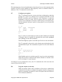
The Qmanager has two double 9 way D plugs and sockets for two separate CANbus
interfaces. The SERVOnet high speed network ports use D-type plug and sockets S4,
parallel-connected; this allows units to be daisy chained together easily with standard
cables. The second interface similarly uses parallel-connected plug and socket S5,
again allowing unit chain or power feed.
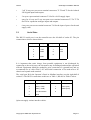
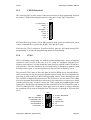
The connections for the CANbus interfaces on the front panel 9 way plugs are shown
below. The plug and socket are connected pin-to-pin, to allow a simple daisy chain
connection. Note that these comply with the CAN in Automation (CiA) draft standard
DS102 Version 2.0, CAN Physical Layer for Industrial Applications, but with
additional signals used for error detection.
Pin no.
Signal
Pin no.
Signal
1
LINK1
6
CAN_0V
2
CAN_L
7
CAN_H
3
CAN_GND
8
CAN_ERR
4
LINK4
9
CAN_V+
(7–13V)
5
CAN_SHLD
(screen)
Table 3: CANbus connections
Note that each CANbus interface requires an external power supply to power the
isolated network transceivers, each connected separately via the D type connectors.
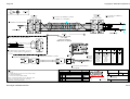
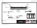
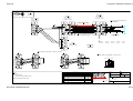
Recommended cable pairing and linking for termination and break-detection are given
in the appendix on drawing QDV-2-2-007, and standard cables are available under
stock code CBA10 003. For further information refer to the SERVOnet handbook.
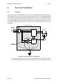
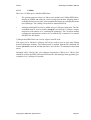
The Qmanager also provides an Ethernet interface using a twisted pair (10baseT or
100baseTX) interface. This uses an 8 way RJ-45 socket, with the transmit pair on pins
1 and 2, receive on 3 and 6, as standard. With EtherCAT netwotk this connects to the
drives, with an Anybus Ethernet card for a programing port.
5.2
Process Logic and Supplies
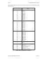
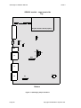
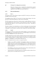
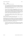
Terminal blocks T1 to T4 are used for the host-level digital inputs and outputs, and T10
for power input. T1 and T2 carry 16 digital inputs: inputs 8:1 to 8:8 and 9:1 to 9:8; T3
gives 8 digital outputs, 8:1 to 8:8. All the 0 volt i/o (T1.10, 2.10, 3.10, and 4.2) and all
the 24 volt i/o pins (T1.1, 2.1, 3.1 and 4.1) are commoned, for ease of sensor wiring.
They are optically isolated from other supplies.
Note that the 24V power supply input is not isolated from the internal logic supplies,
and the 0V supply connection should be earthed.All the screen connections are linked
together to allow a single earth connection for all the cable screens. They are connected
to the metalwork and the D-type connector shells, but are not connected to the system
internal 0V supply. A clean separate earth connection is normally required to the 0V
supply on terminal T10.2 or T10.5.
Page 12
Copyright © 2008 Quin Systems Ltd.