1
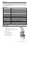
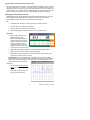
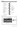
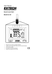
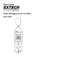
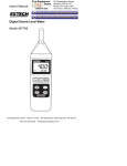
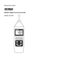
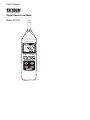
User's Manual
Digital Sound Level Meter
Model 407768
Introduction
Congratulations on your purchase of the Extech 407768 Sound Level Meter. This Auto
Range Sound Level Meter meets ANSI and IEC Type II accuracy standards. Professional
features include programmable Frequency Weighting and Time Response, Min/Max
Memory, Max Hold, Analog output, and RS-232 PC Interface. Careful use of this meter will
provide years of reliable service.
Specifications
Display
Frequency bandwidth
Microphone
Output terminals
Measurement ranges
Frequency weighting
Applicable standards
Resolution
Maximum/Minimum record
Data Hold
Max Hold
Response time
AC Analog output
Power
Operating temperature
Operating humidity
Dimensions / Weight
5 Digit LCD with overload, low battery and multifunction
indication
31.5 Hz to 8 KHz
0.5” Electret Condensor Microphone
Optically isolated RS-232 port and AC output
Auto Range: 30 to 130dB
Manual Ranges: 30 to 80dB, 50 to 100dB, 80 to 130dB
‘A’ and ‘C’ (Programmable)
ANSI / IEC Type 2
0.1dB
Highest and lowest readings are stored for later recall
Displayed reading is held when HOLD key is pressed
Highest reading displayed only
Fast: 125ms / Slow:1s (Programmable)
0.5VAC rms full scale (600Ω output impedance)
9V Battery; Consumption: 6mADC approx.
o
o
32 to 122 F (0 to 50 C)
Less than 80% RH
10.6 x 2.7 x 1.1" / 0.63 lbs. (268 x 68 x 29mm / 285g)
Meter Description
1.
Microphone
2.
LCD Display
3.
Power, Hold, and Min/Max buttons
4.
Max, Weighting, Response Time, & Range buttons
5.
AC output jack
6.
Calibration potentiometer
7.
RS-232 PC interface jack
8.
Battery compartment, tilt stand,
3
and tripod mount on rear
4
1
2
5
6
7
8
2
407768 Version 1.9 12/03
Sound Level Meter Operation
Meter Power
1. The meter is powered by a 9V battery. The battery compartment is located on the rear
of the meter and the compartment cover is secured by one Phillips screw. When the
battery icon appears on the top left corner of the meter's display, replace the battery.
2. Press the POWER button to turn the meter on. Note that the Meter is equipped with an
Auto Power Off feature that shuts the meter off after 10 minutes. To defeat Auto Power
Off, put the meter in Record mode by pressing the REC MAX/MIN button.
3. Press the POWER button to turn the meter off.
Default Configuration
1. The meter's default configuration is as follows: Auto Range, 'A' Frequency Weighting,
and 'FAST' Response Time
2. The lower portion of the LCD will reflect the meter's configuration, i.e., 'A', 'Fast', 'Auto'.
Measurement Considerations
1. Use a windscreen (not included) to cover the microphone in windy conditions.
2. Calibrate the meter often, especially if the meter has been idle for a long period of time.
3. Do not store/operate the meter in areas of high temperature or humidity.
4. Keep the meter and the microphone dry.
5. Avoid severe vibration when using the meter.
6. Remove the battery when the meter will be stored for long periods of time.
Frequency Weighting
Change the Frequency Weighting by pressing the 'A/C' button. The 'A' or 'C' icon will
display on the lower left-hand area of the LCD.
Note: With ‘A’ weighting selected, the meter responds like the human ear (boosting and
cutting the noise amplitude over the frequency spectrum - see Appendix). ‘A’ weighting is
used for environmental measurements, OSHA regulatory testing, law enforcement, and
workplace design. Select ‘C’ weighting for flat response measurements (no boost or cut).
‘C’ weighting is suitable for the sound level analysis of machines, engines, etc. Most OSHA
related testing is performed using 'A' Weighting and SLOW Response Time settings.
Response Time
Change the Response Time by pressing the 'FAST/SLOW' button. The 'FAST' or 'SLOW'
icon will display on the lower left-hand area of the LCD.
Note: Select FAST to capture noise peaks and noises that occur very quickly. In FAST
mode, the meter responds in 200ms. Select the SLOW Mode (meter responds in 500ms)
to monitor a sound source that has a reasonably consistent noise level or to average
quickly changing levels. Selection of Fast or Slow is determined by the application and any
directives or standards related to that application.
Auto/Manual Range
Press the RANGE button to scroll through the following ranges: Auto, 30-80dB, 50-100dB,
and 80-130dB. The display will reflect the range for each button press.
Calibration
The Sound Level meter should be calibrated before each use; an external sound level
meter calibrator is required. Set the meter to the Manual range (50-100dB), FAST
response and ‘A’ weighting before starting.
1. Place the external calibrator over the Sound Level Meter's microphone and turn the
Calibrator on.
407768 Version 1.9 12/03
3
2. The meter should read close to, or exactly, the calibrator's dB output level. Typical
Calibrator output levels are 94dB and 114dB.
3. If the meter is within ± 0.2 dB of the calibrator’s output, no adjustment is necessary.
4. Adjust the calibration pot in the output/calibration compartment if necessary to bring the
meter display in line with the calibrator output signal.
Taking Measurements
1. Hold the meter in hand, place it on a desktop (using the rear tilt stand), or mount it on a
tripod using the tripod mount on the rear of the meter.
2. Point the microphone toward the source of noise/sound to be measured.
3. Read the measurement, in dB units, on the LCD display.
Data Hold
1. Press the HOLD button to freeze the displayed reading. The LCD will display the icon
HOLD when Data Hold is engaged.
2. Press the HOLD button to de-activate this feature. The HOLD icon will extinguish.
3. Note that Data Hold is not available while the meter is in the Max/Min Record mode.
Max Hold
1. Press the MAX HOLD button to activate this feature. The LCD will display PH when
Max Hold is engaged.
2. The meter will now display only the highest reading. Each time a higher reading is
encountered the display will update.
3. Press the MAX HOLD button again to de-activate this feature. The PH icon will
extinguish.
4. Note that Max Hold is not available while the meter is in the Max/Min Record mode.
Max/Min Data Recording
The Max/Min feature stores the maximum reading and minimum reading while the user
takes measurements. The Max and the Min readings can later be recalled.
1. Press the REC MAX/MIN button to activate this feature. The LCD will display the icon
REC and the meter will begin monitoring the highest (Max) and lowest (Min) readings.
2. After measurements are made, press the REC button again to view the Max reading.
The MAX icon will appear on the LCD along with the highest reading.
3. Press the REC to view the minimum (MIN) reading. The 'MIN' display icon will appear
on the LCD along with the lowest reading.
4. To exit this mode, press and hold the REC button until the REC indicator
extinguishes.
5. To clear a Max or Min reading, press the HOLD key while viewing either the MAX or
MIN value. Note that exiting the Record mode also clears the MAX and MIN values.
Analog Output
The AC analog output transmits 0.5V AC rms full scale. The output impedance is
600Ω maximum. The mono 3.5mm mini-jack is located in the output/calibration
compartment on the right side of the instrument. Use a phono plug (3.5mm mono) to
connect to the output jack.
4
407768 Version 1.9 12/03
RS-232 PC Interface Data Acquisition System
The optically isolated RS-232 PC Interface port is located in the output/calibration
compartment situated on the lower right side of the meter. The supplied Data Acquisition
TM
Software package includes Windows 95 / 98 / NT / 2000 / XP compatible software and a
meter-to-PC interface cable.
Hardware Connection
The Digital Sound Level Meter connects to a PC with the supplied interface cable. Connect
the DB-9 end of the cable to the PC COM Port and the mini-plug end to the meter’s port.
Software Installation
1. Insert the supplied software disk in the computer’s CD-ROM drive.
2. Run the SETUP.EXE program included on the software disk.
3. When prompted, select a directory location for the program files.
4. If a message window appears (when installing the software) prompting the user to
overwrite outdated files, cancel the installation. Log onto the Windows Update web
page (http://windowsupdate.microsoft.com/) and download updates as recommended
by the site utility. Perform the recommended updates before attempting to reinstall the
software or contacting tech support.
Software Operation
1. Once the setup is complete, double click the green DataACQ
program icon which resides in the same directory selected in
step 3 of the procedure above.
2. The COM SELECT window (shown at right) opens, prompting
the user to select the PC communications port that will be
used to connect to the meter (typically Com Port 1 or 2).
Ensure that the SLM Enable box is check also then click OK.
3. The DISPLAY TYPE window opens. Select Single Display
then click OK.
4. The DATA_ACQ window will open. Press YES to view
readings and save them in a file. Press NO to view
readings but not save the readings to a file.
5. If YES was selected, the SAVE AS window appears
prompting the user to name the data file and to select
a directory to place it in. The confirmation window
appears showing the new file and its path. Click OK.
6. The DATA COLLECTION window (at right) opens.
Refer to steps a. through d. below:
a. Use the Select Sample Interval scroll bar (click in the white area) to coarsely set
the time between readings (from 1 second to 60 minutes). Click on the arrows at
either end of the bar to fine tune the number.
b. Use the Total Number of Samples selection to save a specific number of
measurements. The range is 1 to 10,000 samples.
c. Use the Start/Stop Time fields to define a data collection time period. The time
period is entered in 24-hour format (HH:MM:SS). The range is 00:00:00 to
23:59:59. Leave this field blank to start logging immediately.
d. Press the START button to begin datalogging.
e. If both Number of Samples and Start/Stop Times are selected, the recording will
begin at the start time and end when either the Stop time or the Total Samples has
been reached, whichever occurs first. FILE CLOSED appears when logging ends.
407768 Version 1.9 12/03
5
Important Note on the Automatic Power OFF feature
The 407768 Sound Level Meter has an AUTO POWER OFF feature that turns the meter
off after approximately 10 minutes. This feature must be disabled before starting a
datalogging session to avoid having the meter automatically shut off in the middle of a
session. Disable it by pressing the REC MAX/MIN button to activate the Record mode.
While the meter is in the Record mode, the AUTO POWER OFF feature is disabled.
Datalogging with the RS-232 PC Interface
Initiate Datalogging by clicking START in the DATA COLLECTION window (shown on the
previous page). The main program window appears (as shown on the cover of this
manual) displaying the Extech logo and the following menu selections:
File
•
Create/Save File: Saves the currently opened file or creates a new file
•
View File: Opens a previously saved data file
•
Close Current File: Closes the file currently open
•
Download Datalogger: Reserved function; not for use with this meter
View Mode
•
Display Analog: Presents the
data as an analog meter.
Note that the Analog display is
scaled using the largest reading
logged. If changes to the unit of
measure are made or if large
changes in readings occur, the
display window should be closed
and re-opened to reset the scaling.
•
Digital: LED-type display with High and Low Reading fields (diagram above).
•
Display File Count: Provides a tally of data points logged.
•
Display Data: Provides logged data in list format. Sample number, reading, time,
and date are provided on each line of list.
Important Note: The Recorded High and Low values (shown above in the display
example) are the highest and lowest values observed at any time during the recording
period. These values, especially for long sample rates, may not be the same as the
high/low values listed in the data file.
Data Graph
•
The graph plots the last 100 data
points in x-y graph format (diagram
right).
•
Print Graph: Prints the graph to a
printer connected to the PC.
6
407768 Version 1.9 12/03
Battery Replacement
The 9V battery that powers the Sound Level Meter is housed in the rear battery
compartment. When the battery icon appears on the top left corner of the meter's LCD, it is
time to replace the battery.
1. Open the battery compartment by first removing the Phillips screw and then sliding the
compartment cover down and off.
2. Replace the 9V battery, slide the cover on, and replace the screw.
Calibration and Repair Services
Extech offers complete repair and calibration services for all of the products we sell.
For periodic calibration, NIST certification or repair of any Extech product, call customer
service for details on services available. Extech recommends that calibration be performed
on an annual basis to insure calibration integrity.
Support Hotline (781) 890-7440
Tech support: Ext. 200; Email: [email protected]
Repair/Returns: Ext. 210; Email: [email protected]
Website: www.extech.com
Warranty
EXTECH INSTRUMENTS CORPORATION warrants this instrument to be free of defects in parts and
workmanship for one year from date of shipment (a six month limited warranty applies on sensors and
cables). If it should become necessary to return the instrument for service during or beyond the warranty
period, contact the Customer Service Department at (781) 890-7440 ext. 210 for authorization or visit our
website at www.extech.com (click on ‘Contact Extech’ and go to Service Department to request an RA
number). A Return Authorization (RA) number must be issued before any product is returned to Extech. The
sender is responsible for shipping charges, freight, insurance and proper packaging to prevent damage in
transit. This warranty does not apply to defects resulting from action of the user such as misuse, improper
wiring, operation outside of specification, improper maintenance or repair, or unauthorized modification.
Extech specifically disclaims any implied warranties or merchantability or fitness for a specific purpose and
will not be liable for any direct, indirect, incidental or consequential damages. Extech's total liability is limited
to repair or replacement of the product. The warranty set forth above is inclusive and no other warranty,
whether written or oral, is expressed or implied.
Copyright © 2001 Extech Instruments Corporation.
All rights reserved including the right of reproduction in whole or in part in any form.
7
407768 Version 1.9 12/03
Appendix
Typical 'A' Weighted dB levels
140
50 HP Siren (100')
130
Jet take-off (200')
Riveting machine
120
110
Chain saw
100
Subway (20')
90
Boiler room
Pneumatic drill (50')
Vacuum cleaner (10')
80
Freight train (100')
70
Speech (1')
Large Office
60
Large store
Residence
50
Small office
Residential area
(night)
40
30
Sound studio
Whisper (5')
20
10
Threshold of hearing
0
Frequency Weighting Graph
dB (relative)
Frequency Weighting
5
0
-5
-10
-15
-20
-25
-30
-35
-40
-45
'A' Weighting
'C' Weighting
10
100
1000
Frequency (Hz)
8
10000
407768 Version 1.9 12/03