1
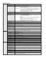
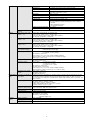
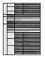
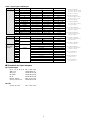
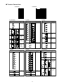
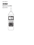
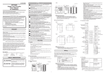
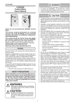
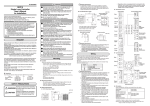
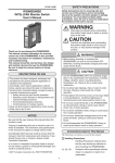
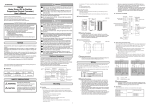
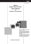
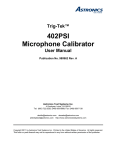
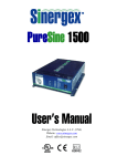
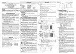
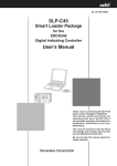
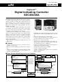
No. CP–SS–1840E
DigitroniKTM
Digital Indicating Controller
SDC45A/46A
The SDC45A/46A DigitroniK (hereafter C45A or C46A)
is a highly advanced, high-precision compact digital indicating controller, featuring dual 5-digit indicators, an
input sampling cycle of 25ms, indication accuracy of
±0.1% of reading, and up to 2 control loops. It offers
PID control using the latest "RationaLOOP" and "JustFiTTER" algorithms.
Up to seven control outputs (depending on the model)
are available, selectable from relay contact, voltage pulse,
triac (for position proportional output), current, continuous voltage, and transmitter power (24Vdc).
Additionally, the controller can be configured with as
many as 14 digital inputs (DIs) and 8 digital outputs
(DOs). A mode change function to handle automatic
equipment operation, a variety of alarms, and various
status outputs are provided to support safe operation. Easy
setup and monitoring from a PC are available using the
Smart Loader Package.
This controller is compliant with IEC directives, and
is CE-marked.
• Full multi-range input, allowing input type to be freely
changed between thermocouple, RTD, current and voltage
• Heat/cool control, using two control outputs
• Using the optional transmitter power supply function, a
pressure transmitter can be directly connected.
• IP65 protection for the front panel
• Up to 16 recipe settings involving SP, event settings, etc.,
and 8 groups of fixed-value control output settings support automatic operation of equipment.
• Support for nonlinear processes using input /output broken line linear approximation tables
• Customizable parameter keys and LED
• A variety of inputs and outputs
2 inputs, 7 outputs, 14 DIs, 8 DOs, 2 CT or AT inputs,
RS-485 communications
• RoHS-compliant
■ Features
• Control, ranging from cascade to backup control, is
available for 1 or 2 loops.
• High-speed 25ms sampling cycle and accuracy of ±0.1%
rdg.
• Ample room for indication of vital information on dual
7-segment, 5-digit LED displays and an auxiliary 11segment, 3-digit LED display
■ Basic Function Block Diagram for the C45A/46A
PV1 input
PV2 input
External switch
inputs (14 max.)
Linearization MV Output
limit
table
Thermocouple, RTD, DC current, DC voltage
Digital filter
Ratio/bias
Square root operation
Linear approximation
Thermocouple, RTD, DC current, DC voltage
Digital filter
Ratio/bias
Square root operation
Linear approximation
Set point (SP) value, 16 groups of selection
RUN/READY selection
AUTO/MANUAL selection
LSP/RSP selection
Latch cancellation
Linearization table selection, etc.
AUX
Control Operation
PID control (1 loop,
2 loops, cascade*)
Direct/reverse action
Heat/cool action
Computer backup
Event configuration
AUTO/
MANUAL
• Current or continuous voltage output
Relay contact
Voltage pulse
Current
Continuous voltage
Triac (position proportional output)
(The above output types may be combined;
see Model Selection Guide section for details.)
Outputs
(7 max.)
EV is relay contact output
Motor feedback (MFB) input
2 current transformer
(CT) inputs*
AC input*
Communications
input/output
SP/PV/DEV/
RSP/MV/MFB
Fixed value
outputs 1 to 8
EV
RS-485 (3-wire)
Power
100 to 240Vac
24Vac/24Vdc*
1
SP/PV/DEV/RSP/MV/MFB
Various status/controller alarms
DOs
(8 max.)
PC loader software
Loader
communications
*Available in the near future.
■ Specifications
Analog input
Input type
Full multi-range input: thermocouple, RTD, DC current and DC voltage
Input sampling time
25ms, 50ms, 100ms, 300ms (according to the setting)
Input bias current
Thermocouple input: -0.2µA (upscale burnout indication)
(under standard conditions)
+0.13µA (downscale burnout indication)
±0.05µA (no burnout detection)
Note: Negative current flow is from terminal B, positive is to terminal B.
DC voltage input:
-0.2µA in the ±100mV range and lower ranges (upscale burnout indication)
+0.13µA in the ±100mV range and lower ranges (downscale burnout indication)
±0.05µA in the ±100mV range and lower ranges (burnout detection)
±1µA or less in the 0 to 1V and -1 to +1V ranges
-5µA or less in the 1 to 5V and 0 to 5V ranges
-10µA or less in the 10V range
Input impedance
Current input: 110Ω or less
Measuring current
RTD input: 1.0mA ±2%
Influence of wiring
Thermocouple input: 0.2µV/Ω (upscale burnout indication)
resistance
0.13µV/Ω (downscale burnout indication)
(under standard conditions)
0.05µV/Ω (no burnout detection)
DC voltage input:
RTD input allowable wiring
resistance
0.2µV/Ω or less in the ±100mV range and lower ranges (upscale burnout
indication)
0.13µV/Ω or less in the ±100mV range and lower ranges (downscale burnout
indication)
0.05µV/Ω in the ±100mV range and lower ranges (burnout detection)
1µV/Ω or less in the 0 to 1V and -1 to +1V ranges
5µV/Ω or less in the 1 to 5V and 0 to 5V ranges and lower ranges
10µV/Ω or less in the 10V range and lower ranges
85Ω or less (Zener barrier + wire, per wire)
Max. allowable input
Thermocouple input, DC voltage input (in the 100mV range and lower ranges): -1.0 to +2.5Vdc
Burnout indication
Varies with input range
Over-range detection
threshold
Varies with upper/lower limit value of PV range or input range (fixed)
Cold junction compensation accuracy
±0.5°C (under standard conditions)
Infl. of ambient temp. on
±1.0°C (in the 0 to 50°C range under standard conditions)
cold junction compensation
Cold junction compensation method
Internal/external (0°C only) compensation selectable
Scaling
-19999 to +32000U (Linear DC voltage/current input only. Reverse scaling and decimal point repositioning available. Effective resolution depends on the range.)
Indicators and PV, SP indication
configuration
5-digit, 7-segment LED. PV: green or orange (depending on the model) upper display. SP: lower
orange display.
Auxiliary indication
3-digit, 11-segment orange LED
Multi-status indicator
12-segment LED, green or orange (depending on the model). Displays status of control output, alarm,
RUN/READY, etc.
No. of status displays
C45A: 17, C46A: 19 LED displays
Operation keys
C45A: 11, C46A: 13 rubber keys
Number of local set points
16 groups
Memory storage system
EEPROM
Indicating range
-19999 to +32000U (or to the SP limit, if it is set)
SP limits
Lower limit: -19999 to upper limit value. Upper limit: lower limit value to 32000U.
SP ramp
0.0 to 3200.0s, min, or h (both up- and down-ramp), Disabled if 0.0 is selected.
Input readout accuracy
±0.1% FS ±1 digit (depending on the range; see Table 1)
Indicating range
See Table 1
Digital input
Number of inputs
C45A: 10 max. C46A: 14 max.
(DI)
Types of connectable outputs Dry contact or open-collector (open drain, sink)
Open terminal voltage
7 Vdc±15% (under standard conditions)
Terminal current
(during short-circuit)
3 to 5 mA (optional 8 or 12 inputs under standard conditions), 3 to 7mA (standard 2 inputs under
standard conditions)
Allowable contact resistance (dry contact)
500Ω or less (under standard conditions)
Allowable open-collector
ON-state residual current
1.5V or less (under standard conditions)
Allowable open-collector
OFF-state leakage current
100µA or less (under standard conditions)
Sampling cycle
25ms
Computation cycle
25ms, 50ms, 100ms, 300ms (depending on the setting)
Min. detection holding time 2 times the input sampling cycle
Assignable functions
RUN/READY, AUTO/MANUAL, REMOTE/LOCAL, auto tuning start/stop, control action direct/reverse
selection, SP group/recipe group selection, fixed value outputs 1 to 8 selection, linear approximation
table selection, computer backup selection
2
Control
Output
Digital Output
(DO)
Auxiliary
output
PID control
Proportional band (P)
0.1 to 3200.0%
Integral time (I)
0 to 32000, 0.0 to 3200.0, 0.00 to 320.00 seconds
Derivative time (D)
0 to 32000, 0.0 to 3200.0, 0.00 to 320.00 seconds
MV limit
Lower limit: -10.0 to upper limit %
Upper limit: lower limit to +110.0%
Manual reset
-10.0 to +110.0%
Number of PID groups
16
PID group selection
By console or DI
MV change limit
0.00 to 320.00%/s, no limit at 0.0%
Auto tuning
Automatic PID value setting by limit cycle method. Additionally,
one of the following 3 control characteristics can be selected:
• Standard
• Quick disturbance response
• Less up/down fluctuation
Position proportional dead zone
0.5 to 25.0%
Heat/cool dead zone
-100.0 to +100.0%
Direct/reverse action
selection
Available
Relay contact, form 1a1b
(outputs 1 & 2)
Contact rating: 250Vac/30Vdc, 3A (resistive load)
Contact voltage: 250Vac or less / 125Vdc or less
Service life: 100,000 cycles or more (under rated conditions)
Min. switching specifications: 100mA/5Vdc
Relay contact, form 1a
(outputs 1 & 2)
Contact rating: 250Vac/30Vdc, 1A (resistive load)
Contact voltage: 250Vac or less / 110Vdc or less
Service life: 100,000 cycles or more (under rated conditions)
Min. switching specifications: 10mA/5Vdc
Relay contact , form 1a
(outputs 3 to 5)
Contact rating: 250Vac/30Vdc, 3A (resistive load)
Contact voltage: 250Vac or less / 125Vdc or less
Service life: 100,000 cycles or more (under rated conditions)
Min. switching specifications: 100mA/5Vdc
Triac (outputs 3 & 4, position proportional output)
Compatible motors: ECM3000*11 * 0 (100Vac type)
ECM3000F1200 (100Vac type)
Current (outputs 3 to 7)
Output current:
Voltage pulse
Output voltage: 12Vdc+15%/-10%
Load current: 30mA or less
Continuous voltage
Output voltage:
0 to 5Vdc (0.0 to 5.5Vdc)
1 to 5Vdc (0.6 to 5.4Vdc)
0 to 10Vdc (0.0 to 11.0Vdc)
Load resistance: 1kΩ or more
Load limit current: 12mA or more
Output accuracy: ±0.1% FS or less (under standard conditions)
Output resolution: 1/20000 or more (in the 1 to 10Vdc FS range)
Transmitter power supply
function
Output voltage: 24Vdc±10%
Load current: 30mA or less
Load limit current: 45mA
Event types (assignable to
relay output)
PV direct, PV reverse, deviation direct, deviation reverse, absolute value deviation direct, absolute
value deviation reverse, MV direct, MV reverse, RSP direct, RSP reverse, SP direct, SP reverse,
sum of all alarms, PV range alarm, controller alarm, manual status, READY status, local status, auto
tuning execution
Settable ranges
PV (direct, reverse): -19999 to +32000U
RSP (direct, reverse): -19999 to +32000U
Deviation (direct, reverse): -19999 to +32000U
Absolute value deviation (direct, reverse): 0 to +32000U
MV (direct, reverse): -10.0 to +110.0%
Operation differential
(hysteresis) setting range
0 to 200U (except MV, MFB event, process alarm)
0.0 to 20.0% for MV, MFB event, process alarm
ON delay time
0.1 to 3200.0 seconds
4 to 20mAdc (2.4 to 21.6mAdc)
0 to 20mAdc (0.0 to 22.0mAdc)
Load resistance: 600Ω or less
Output accuracy: ±0.1% FS or less (under standard conditions)
Output resolution: 1/15000 or more (in the 0 to 20mAdc FS range)
Voltage (open): 23Vdc or less
Output operation
ON/OFF action, latch action
Output rating
Output type: open-collector (open drain) sink method
Load resistance: 4.5 to 28Vdc
Load current: 70mA/output max.
500mA/all outputs max.
Number of outputs
4 max. assignable
Output types
PV, SP, DEV, RSP, MV, MFB, etc. can be selected
Output method
Current or continuous voltage
3
Communica-
Communications system
tions
Interface
Message characters
PC loader
Current
transformer
(CT) input
Communications line
Protocol
RS-485
Network
Multidrop. Slave station only. Connect up to 31 units.
Data flow
Half-duplex
Synchronization method
Start/stop synchronization
Transmission system
Balance (differential) type
Transmission type
Bit serial
Transmit/receive lines
3
Speed
4800, 9600, 19200, 38400 bps
Distance
500m max.
Protocol
RS-485 (3-wire type)
Character configuration
9 to 12 bits/character
Data length
7 or 8 bits
Stop bit length
1 or 2 bits
Parity bit
Even parity, odd parity, or non-parity
3-wire type
Communications speed
38400 bps (fixed)
Recommended cable
Dedicated cable
Number of inputs
2
Detection function
When control output is ON: heater line break or overcurrent detection
When control output is OFF: final control device short circuit detection
Input device
Current transformer (sold separately), 800 turns
• QN212A, 5.8mm dia. hole
• QN206A, 12mm dia. hole
Input range
AC 0.0 to 50.0A
Measurement current range AC 0.4 to 55.0A
Indication accuracy
General
specifications
±3% FS ± 1 digit (AC 0.4A or more, under other standard conditions, excluding CT accuracy)
Indication resolution
AC 0.1A
Memory backup
EEPROM
Power
100 to 240Vac, 50/60Hz ± 2Hz
Power consumption
C45A: 30VA or less. (100 to 240Vac power model) C46A: 40VA or less. (100 to 240Vac power model)
Power ON inrush current
35A or less/10ms or less (100 to 240Vac power model)
Power ON operation
Reset time: 6s max. (time until normal operation starts under standard conditions)
Allowable transient power
loss
20ms or less
Insulation resistance
20MΩ or more between power supply terminal 1 or 2 and FG terminal 3 (500Vdc megger)
Dielectric strength
1500Vac for 1min (100 to 240Vac power model)
• Between power supply terminal 1 or 2 or FG terminal 3 and secondary terminal
• Between power supply terminal 1 or 2 and FG terminal 3
Standard conditions
Operating conditions
Transportation conditions
Ambient temperature
23±2°C
Ambient humidity
60±5% RH
Power voltage
105Vac±1%
Power frequency
50±1Hz or 60±1Hz
Vibration resistance
0m/s2
Shock resistance
0m/s2
Mounting angle
Reference plane ±3°
Clear space
100mm min. vertically and horizontally
Ambient temperature
0 to 50°C
Ambient humidity
10 to 90% RH (without condensation)
Power voltage
85 to 264Vac
Power frequency
50±2Hz or 60±2Hz
Vibration resistance
0 to 2m/s2 (10 to 60Hz for 2h each in X, Y, and Z directions)
Shock resistance
0 to 10m/s2
Mounting angle
Reference plane ±10°
Altitude
2000m max.
Clear space
50mm min. above and below
Ambient temperature
-20 to 70°C
Ambient humidity
10 to 95% RH (without condensation)
Vibration resistance
0 to 5m/s2 (10 to 60Hz for 2h each in X, Y, and Z directions)
Shock resistance
0 to 500m/s 2 (3 times each in X, Y, and Z directions)
Front panel protection
IP65
Console and case material
Polyphenylene oxide
Console and case color
Black
Standards compliance
EN61010-1 (CE-LVD), EN61326 (CE-EMC), RoHS
Overvoltage category
Category II (IEC60364-4-443, IEC60664-1)
Mounting
Panel mounted (with dedicated mounting bracket)
Mass
C45A: Approx. 400g (including dedicated mounting bracket)
C46A: Approx. 700g (including dedicated mounting bracket)
4
Accessories
(included)
Part name
Mounting brackets (2)
Gasket
Model
Optional parts
(sold separately)
81405411-004
Part name
Mounting brackets (2)
81421863-001 (for C45A)
Current Transformer
81421864-001 (for C46A)
User's manual
Model
81405411-003
QN206A (5.8mm dia. hole)
QN212A (12mm dia. hole)
CP-UM-5445E
Hard cover
81441421-001 (for C45A)
81441422-001 (for C46A)
Terminal cover
5
81441420-001 *
* 1 for C45A, 2 for C46A
Table 1 Input Types and Ranges
Input type
Pv-01
Sensor type
Thermocouple
1
K
2
E
-270.0 to +1000.0°C
-454 to +1832°F
±0.1% rdg. ±1 digit *2
3
J
-200.0 to +1200.0°C
-328 to +2192°F
±0.1% rdg. ±1 digit *3
4
T
-270.0 to +400.0°C
-454 to +752°F
±0.5°C *4
5
B
0.0 to 1800.0°C
32 to 3272°F
±2.0°C *5
6
R
-50.0 to +1768.0°C
-58 to +3214°F
±0.1% rdg. ±1 digit *6
7
S
-50.0 to +1768.0°C
-58 to +3214°F
±0.1% rdg. ±1 digit *6
8
W (WRe5-26)
0.0 to 2300.0°C
32 to 4172°F
±0.1% rdg. ±1 digit *7
9
PR40-20
0.0 to 1900.0°C
32 to 3452°F
±8.0°C *8
10
Ni-NiMo
0.0 to 1300.0°C
32 to 2372°F
±1.4°C
1 1
N
-200.0 to +1300.0°C
-328 to +2372°F
±1.4°C *9
12
PL II
0.0 to 1390.0°C
32 to 2534°F
±1.4°C
13
DIN U
-200.0 to +600.0°C
-328 to +1112°F
±0.7°C *10
14
DIN L
-200.0 to +900.0°C
-328 to +1652°F
±1.0°C *11
15
Golden-iron/Chromel
-273.0 to +27.0°C
-459 to +80°F
±1.5°C
Pv-01
Sensor type
21
Pt100
Input type
RTD
22
31
JPt100
32
Linear
(DC voltage
/current)
41
Range
-270.0 to +1372.0°C
Range
-200.0 to +850.0°C
±0.1% rdg. ±1 digit *1
Accuracy
-328.0 to +1562.0°F
±0.3°C
-200.00 to +300.00°C -328.00 to +572.00°F
±0.15°C
-200.0 to +640.0°C
-328.0 to +1184.0°F
±0.3°C
-200.00 to +300.00°C -328.00 to +572.00°F
±0.15°C
Current
42
43
Accuracy
-454 to +2502°F
Voltage
4 to 20mA
±0.1% FS ±1 digit
0 to 20mA
±0.1% FS ±1 digit
0 to 10mV
±0.1% FS ±1 digit
44
-10 to +10mV
±0.1% FS ±1 digit
45
0 to 100mV
±0.1% FS ±1 digit
46
-100 to +100mV
±0.1% FS ±1 digit
47
0 to 1V
±0.1% FS ±1 digit
48
-1 to +1V
±0.1% FS ±1 digit
49
1 to 5V
±0.1% FS ±1 digit
50
0 to 5V
±0.1% FS ±1 digit
51
0 to 10V
±0.1% FS ±1 digit
■ Standards for input sensors
● Thermocouple
K, E, J, T, B, R, S, N: JIS C 1602-1995
WRe5-26:
ASTM E988-96
PR40-20:
ASTM E1751-00
Ni-NiMo:
ASTM E1751-00
PL II:
ASTM E1751-00
DIN U, DIN L:
DIN 43710-1985
Gold-iron/Chromel:
ASTM E1751-00
● RTD
Pt 100, JPt 100:
JIS C 1604-1989
6
*1: At 400°C and above.
±0.5°C (< +400 to –100°C)
±1.0°C (< –100 to –200°C)
±20.0°C (< -200°C)
*2: At 400°C and above.
±0.5°C (<+400 to –100°C)
±1.0°C (<-100 to –200°C)
±15.0°C (<-200°C)
*3: At 400°C and above.
±0.5°C (<+400 to –100°C)
±1.0°C (<-100°C)
*4: At -100°C and above.
±1.0°C (< -100 to –200°C)
±10.0°C (< -200°C)
*5: At 800°C and above.
±4.0°C (< 800 to 260°C)
±70°C (< 260°C)
*6: At 1000°C and above.
±2.0°C (< 1000°C to 0°C)
±4.0°C (< 0°C)
*7: At 1400°C and above.
±1.5°C (< 1400°C)
*8: At 800°C and above.
±20.0°C (< 800 to 300°C)
±40.0°C (< 300°C)
*9: At 0°C and above.
±4.0°C (< 0°C)
*10: At 0°C and above.
±1.0°C (< 0°C)
*11: At 0°C and above.
±1.5°C (< 0°C)
■ C45A Model Selection Guide
● Choose the appropriate type of model number:
●
●
● Detailed Model No.
I
II
III
Basic
Model
Inputs
Power
Detailed Model Number
Specifications required for a particular application can be selected in detail, allowing purchase of
the optimal device (especially useful for equipment manufacturers).
Combined Function Model Number
Easy selection from premade combinations of required functions. Selections have multiple I/Os,
so these devices can be used flexibly for a variety of application requirements (especially useful
for engineering manufacturers and factory maintenance staff).
I
IV
II
III
V
IV
VI
Outputs 1 Outputs 3
and 2 *1
and 4 *2
V
VI
VII
VII VIII IX
VIII
IX
Ex.: C45A1A1C000000
X
X
Descriptions
Output Outputs 6 Options Additional Additional
5 *3
and 7 *3
features 1 features 2
C45A
Remarks
Standard model
1
1 full multiple input
2
2 full multiple inputs
A
AC power
1
Relay contact output, 1a1b
2
2 relay contact outputs, form 1a
Available soon
Available soon
C0
Current output (output 3)
D0
Continuous voltage output (output 3)
With 2 DIs
With 2 DIs
V0
Voltage pulse output (output 3)
With 2 DIs
V1
Voltage pulse output (output 3)
With 2 CT inputs
RR
2 relay contact outputs, form 1a
With 2 DIs
CC
2 current outputs
With 2 DIs
VV
2 voltage pulse outputs
With 2 DIs
CV
Current output (output 3) + voltage
pulse output (output 4)
With 2 DIs
Triac output + triac output
With 1 MFB input
SS
0
None
R
Relay contact output, 1a
C
Current output
D
Continuous voltage output
P
Transmitter Power supply
0
None
*1.
Outputs 1 and 2 are mainly for event (alarm) output.
0
None
*2.
Outputs 3 and 4 are used mainly for control output.
1
8 additional DIs
*3.
Optional outputs 5–7 are used for auxiliary output or
2
8 DOs
for transmitter power supply.
3
8 DOs + RS-485 communications
0
None
T
Tropicalization
K
Antisulfidization corrosion treatment
D
Inspection certification
B
Tropicalization + inspection certification
L
Antisulfidization corrosion treatment +
inspection certification
0
None (standard LED colors)
1
All-orange LEDs
● Combined Function Model No. (with all-orange LED displays)
I
II
III
IV
Basic model No.
Set No.
Option 1
Option 2
I
II
III
IV
Ex.: C45A000
Descriptions
C45A
Standard model, with 2 alarm outputs
0
Available soon
Available soon
(Reserved for future use)
0
Regular type 1: Plus 1 current output, 2 relay outputs, and 2 DIs
1
Regular type 2: Plus 1 current output, 1 voltage pulse output, 1 relay output, and 2 DIs
2
Position proportion type: Plus 1 relay output
3
Regular type 3: Plus 2 current outputs, transmitter power supply (24V), and 2 DIs
4
Position proportion type: Plus transmitter power supply (24V)
0
None
1
RS-485 communications, PV input 2, 8 DOs
2
PV input 2, 8 DOs
3
8 DOs
4
PV input 2
7
■ C46A Model Selection Guide
● Choose the appropriate type of model number:
●
●
● Detailed Model No.
I
II
III
Basic
Model
Inputs
Power
Detailed Model Number
Specifications required for a particular application can be selected in detail, allowing purchase of
the optimal device (especially useful for equipment manufacturers).
Combined Function Model Number
Easy selection from premade combinations of required functions. Selections have multiple I/Os,
so these devices can be used flexibly for a variety of application requirements (especially useful
for engineering manufacturers and factory maintenance staff).
I
IV
II
III
V
IV
VI
Outputs 1 Outputs 3 Output
and 2 *1
and 4 *2
5 *3
V
VI
VII
VII VIII IX
VIII
Outputs 6 Options
and 7 *3
IX
Ex.: C46A1A1C000000
X
X
Descriptions
Additional Additional
features 1 features 2
C46A
Remarks
Standard model
1
1 full multiple input
2
2 full multiple inputs
A
AC power
1
Relay contact output, 1a1b
2
2 relay contact outputs, form 1a
Available soon
C0
Current output (output 3)
D0
Continuous voltage output (output 3)
With 2 DIs
With 2 DIs
V0
Voltage pulse output (output 3)
With 2 DIs
V1
Voltage pulse output (output 3)
With 2 CT inputs
RR
2 relay contact outputs, form 1a
With 2 DIs
CC
2 current outputs
With 2 DIs
VV
2 voltage pulse outputs
With 2 DIs
CV
Current output (output 3) + voltage pulse
With 2 DIs
output (output 4)
Available soon
SS
Triac output + triac output
0
None
R
Relay contact output, 1a
C
Current output
D
Continuous voltage output
P
With 1 MFB input
Transmitter power supply
0
None
1
Current output (output 6)
2
Transmitter power supply (output 7)
3
Current + current output* 4
4
Current output (output 6) + transmitter
power supply (output 7)
0
None
1
12 additional DIs
2
12 DIs + 8 DOs
3
12 DIs + 8 DOs + RS-485 communications
*1.
Outputs 1 and 2 are mainly for event (alarm) output.
0
None
*2.
Outputs 3 and 4 are used mainly for control output.
T
Tropicalization
*3.
Optional outputs 5–7 are used for auxiliary output or for transmitter
power supply
K
Antisulfidization corrosion treatment
D
Inspection certification
Not available if “CC” is selected for outputs 3–4 and “C” is selected
for output 5.
B
Tropicalization + inspection certification
L
Antisulfidization corrosion treatment +
inspection certification
*4.
0
None (standard LED colors)
1
All-orange LEDs
● Combined Function Model No. (with all-orange LED displays)
I
II
III
IV
Basic model No.
Set No.
Option 1
Option 2
I
II
III
IV
Ex.: C46A000
Descriptions
C46A
Standard model, with 1 current output and 2 alarm outputs
0
Available soon
Available soon
(Reserved for future use)
0
Regular type 1: Plus 1 current output, 2 relay outputs, and 2 DIs
1
Regular type 2: Plus 1 current output, 1 voltage pulse output, 1 relay output, and 2 DIs
2
Position proportion type: Plus 1 relay output
3
Regular type 1 + additional transmitter power supply (24V)
4
Position proportion type + additional transmitter power supply (24V)
0
None
1
RS-485 communications, PV input 2, 12 DIs, 8 DOs
2
PV input 2, 12 DIs, 8 DOs
3
2 DIs, 8 DOs
4
PV input 2
8
■ Dimensions
(Unit: mm)
● C45A
11
48
43.8
130
Gasket
(Accessory)
110
96
91.4
2
Mounting bracket
(Accessory)
M3 terminal screw
● C46A
11
96
130
91.4
Gasket
(Accessory)
110
96
91.4
2
Mounting bracket
(Accessory)
M3 terminal screw
Precautions in Handling
When fastening this controller onto the panel, tighten the mounting bracket screws until there is no play
between the bracket and panel, and then turn one more turn. Overtightening the screws may deform the
controller case.
Panel cutout diagram
• C45A
• C46A
Gang-mounting
92 +0.5
0
(96xN-4) +0.5
0
+0.5
+0.5
0
92
50 min.
92 0
+0.5
0
Gang mounting
Stand-alone mounting
(48xN-4) +0.5
0
+0.5
0
44 +0.5
0
92
50 min.
50 min.
92
Stand-alone mounting
50 min.
●
Precautions in Handling
If three or more units are gang-mounted horizontally, the maximum allowable ambient temperature is 40°C.
9
■ Console Parts and Functions
● C46A Front Panel
● C45A Front Panel
(7)
(5)
(1)
(6)
(5)
(3)
(5)
(7)
(1)
(3)
(2)
(6)
(2)
(11)
(9)
(5)
(4)
(11)
(10)
(13)
(10)
(13)
(12)
(17)
(12)
(17)
(4)
(8)
(9)
(16) (15)
(16) (15) (14) (14) (8)
(1) Upper display: for PV values (present temperature,
etc.) or setup items.
(2) Lower display: for SP values (set temperature, etc.)
or other parameter values.
(3) Auxiliary display: for setup items or tag names.
(4) Multi-status (MS) indicator: for MV, DI/DO
status, etc.
(5) Mode indicator lights
rdy:
Ready
rsp:
Remote setup input
man: Manual
out1–7: Control outputs 1–7, (1–5 for C45A)
(6) User function indicators
uf1–4: Display user-assigned items, (uf1, 2 for
C45A)
(7) Loop number indicators
pv1, pv2: Indicate the loop number of the displayed PV value
(8) v, ^, <, >: Increment numeric values and shift between digits or settable items.
(9) auto/man: Changes AUTO/MANUAL mode.
(10) sp/ev: Selects or sets LOCAL SP or EVENT.
(11) display: Changes the display contents in operation
display mode.
(12) para:
Changes the setting mode.
(13) enter:
Used during setup, especially to finalize
the user’s selection of a value.
(14) f1–f2: Perform user-assigned functions (C46A
only).
(15) at:
For auto-tuning executing/cancellation, or
for user-assigned functions.
(16) rsp/lsp: Changes between remote and local set
point, or executes user-assigned functions.
(17) Loader jack: For connection of PC loader cable.
10
■ Terminal Connections
C45A Back
C46A Back
A
C F
A (C45A/46A)
C (C45A)
C (C46A)
Details
Details
(1)
Power
(1) AC model:
100 to 240 Vac
(1)
(2)
COM( )
C1
(1)
(2)
1
1
2
2
(1)
Outputs 1, 2
(OUT1/OUT2)
(1) Relay (1a1b)
(2) Relay (1a)
(3)
Output 3 (OUT3)
(1) Relay
(3) Current,
voltage pulse,
continuous
voltage
(1)
(3)
Output 4 (OUT4)
(1) Relay
(3) Current,
voltage pulse
(1)
(2)
Output 5 (OUT5)
(1) Relay
(2) Current,
continuous
voltage,
transmitter
power supply
Digital input (DI)
C1
C1
C2
C2
C3
C3
C4
C4
C5
C5
C6
C6
C7
C7
C8
C8
C2
C3
C4
Output 6 (OUT6)
Current
Output 7 (OUT7)
Current
Transmitter power
supply
RS-485
communications
DA
D (C46A)
Details
Digital input/output
(DI/DO)
(1) DI
(2) DO
DB
DB
SG
SG
E (C46A)
RS-485
communications
DA
F (C45A/46A)
Details
Details
Digital input
(DI)
Details
Digital output
(DO)
COM( )
(1)
Other
(1) Digital input (DI)
D1
E1
F1
D2
E2
F2
D3
E3
D4
E4
D5
E5
D6
E6
B
D7
E7
C
D8
E8
Unused
(1)
(2)
A
(4)
PV input 2 (PV2)
(1) Thermocouple
(2) RTD (3-wire)
(4) DC voltage/
current
V/mA
mV
(1)
Unused
(2)
A
(4)
Unused
V/mA
B
mV
C
11
PV input 1 (PV1)
(1) Thermocouple
(2) RTD (3-wire)
(4) DC voltage/
current
RESTRICTIONS ON USE
This product has been designed, developed and manufactured for general-purpose application in machinery and equipment.
Accordingly, when used in the applications outlined below, special care should be taken to implement a fail-safe and/or redundant
design concept as well as a periodic maintenance program.
• Safety devices for plant worker protection • Start/stop control devices for transportation and material handling machines
• Aeronautical/aerospace machines
• Control devices for nuclear reactors
Never use this product in applications where human safety may be put at risk.
Specifications are subject to change without notice.
Advanced Automation Company
1-12-2 Kawana, Fujisawa
Kanagawa 251-8522 Japan
URL: http://www.azbil.com
Printed in Japan. (H)
1st Edition: Issued in May, 2007
No part of this publication may be reproduced or duplicated
without the prior written permission of Yamatake Corporation.
12