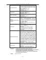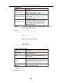
1
DAS-3248
48-Port IP DSLAM
User’s Manual
First Edition (August 2004)
Version 1.0
Printed In Taiwan
RECYCLABLE
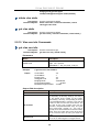
D-Link DAS-3248 ADSL IP DSLAM
____________________
Information in this document is subject to change without notice.
© 2003 D-Link Corporation. All rights reserved.
Reproduction in any manner whatsoever without the written permission of D-Link
Corporation is strictly forbidden.
Trademarks used in this text: D-Link, the D-LINK logo are trademarks of D-Link Computer
Corporation; Microsoft and Windows are registered trademarks of Microsoft Corporation.
Other trademarks and trade names may be used in this document to refer to either the
entities claiming the marks and names or their products.
D-Link Computer Corporation disclaims any proprietary interest in trademarks and trade
names other than its own.
August 2004 P/N DAS3248UM01V10
i
FCC Warning
This equipment has been tested and found to comply with the limits for a Class A digital device, pursuant to part
15 of the FCC Rules. These limits are designed to provide reasonable protection against harmful interference in
a residential installation. This equipment generates, uses and can radiate radio frequency energy and, if not
installed and used in accordance with the instructions, may cause harmful interference to radio communications.
However, there is no guarantee that interference will not occur in a particular installation. If this equipment does
cause harmful interference to radio or television reception, which can be determined by turning the equipment
off and on, the user is encouraged to try to correct the interference by one or more of the following measures:
-Reorient or relocate the receiving antenna.
-Increase the separation between the equipment and receiver.
-Connect the equipment into an outlet on a circuit different from that to which the receiver is connected.
-Consult the dealer or an experienced radio/ TV technician for help.
CE Mark Warning
This is a Class A product. In a domestic environment, this product may cause radio interference, in which case
the user may be required to take adequate measures.
Warnung!
Dies ist in Produkt der Klasse A. Im Wohnbereich kann dieses Produkt Funkstoerungen verursachen. In diesem
Fall kann vom Benutzer verlangt werden, angemessene Massnahmen zu ergreifen.
Advertencia de Marca de la CE
Este es un producto de Clase A. En un entorno doméstico, puede causar interferencias de radio, en cuyo case,
puede requerirse al usuario para que adopte las medidas adecuadas.
Attention!
Ceci est un produit de classe A. Dans un environnement domestique, ce produit pourrait causer des
interférences radio, auquel cas l`utilisateur devrait prendre les mesures adéquates.
Attenzione!
Il presente prodotto appartiene alla classe A. Se utilizzato in ambiente domestico il prodotto può causare
interferenze radio, nel cui caso è possibile che l`utente debba assumere provvedimenti adeguati.
ii
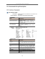
TABLE OF CONTENTS
List of Figures ................................................................................... vii
List of Tables.................................................................................... viii
About This Manual.............................................................................. 1
What’s the difference between ATM based DSLAM and IP based
DSLAM? ............................................................................................... 3
1
Introduction................................................................................... 6
1.1
General.........................................................................................................6
1.2
DAS-3248 Overview ....................................................................................7
1.3
DAS-3248 Application ...............................................................................10
1.4
DAS-3248 Features ................................................................................... 11
1.4.1
1.4.2
1.4.3
1.5
2
Cost Saving Solution for SMB......................................................................... 11
Excellent Management with Security .............................................................. 11
Advanced Function for Broadband Service Offering....................................... 11
DAS-3248 Specifications ..........................................................................13
Getting Started ............................................................................ 15
2.1
General.......................................................................................................15
2.2
Unpacking your DAS-3248 .......................................................................16
2.3
Hardware Installation ................................................................................17
2.3.1
2.3.2
2.3.3
2.4
Ways of Management Connection ...........................................................20
2.4.1
2.4.2
2.4.3
3
Safety Instruction ............................................................................................ 17
DAS-3248 Rear Panel Connection ................................................................. 18
DAS-3248 Front Panel Connection................................................................. 19
EMS(Element Management System).............................................................. 20
Command Line Interface (CLI)........................................................................ 21
Telnet Client .................................................................................................... 22
EMS Configuration ..................................................................... 23
3.1
EMS Functions ..........................................................................................23
3.1.1
3.1.2
3.1.3
3.1.4
3.1.5
3.1.6
3.2
Installation....................................................................................................... 24
Un-installation of NetBailiff.............................................................................. 29
Starting the System......................................................................................... 31
Logging into the System ................................................................................. 32
Terminating the System .................................................................................. 33
Logging out the Current Session .................................................................... 33
Windows Arrangement .............................................................................33
iii
3.2.1
3.2.2
3.2.3
3.2.4
3.3
Tools Menu Introduction...........................................................................35
3.3.1
3.3.2
3.3.3
3.3.4
3.3.5
4
Cascade.......................................................................................................... 33
Next Window................................................................................................... 34
Previous Window ............................................................................................ 34
Arrange Icons ................................................................................................. 34
Environmental Options.................................................................................... 35
Territory manager configuration ...................................................................... 39
Agent Manager Configuration ......................................................................... 41
Mounted Agent Desktop.................................................................................. 46
Telnet .............................................................................................................. 46
Manage the DAS-3248 ................................................................ 52
4.1
Activate Function Management Windows...............................................52
4.1.1
Function management Windows..................................................................... 53
4.2
Default Setting...........................................................................................54
4.3
System Information...................................................................................55
4.4
Current Event ............................................................................................57
4.5
System .......................................................................................................60
4.5.1
4.6
Configuration.............................................................................................61
4.6.1
4.6.2
4.6.3
4.7
Profile Configuration ....................................................................................... 66
Port Configuration ........................................................................................... 69
DSL Performance Management ...............................................................70
4.8.1
4.8.2
4.8.3
4.8.4
5
VLAN Configuration ........................................................................................ 61
Ethernet Configuration .................................................................................... 63
Static Multicast Configuration.......................................................................... 64
DSL .............................................................................................................66
4.7.1
4.7.2
4.8
Commit and Reboot ........................................................................................ 60
Physical Layer Info.......................................................................................... 70
Channel Layer Info.......................................................................................... 72
Physical Layer PM .......................................................................................... 73
Channel Layer PM .......................................................................................... 75
System Administration with CLI................................................ 78
5.1
Notation Conventions ...............................................................................78
5.2
Command Structure..................................................................................78
5.3
Glossary of Terms and Acronyms ...........................................................79
5.4
CLI Command Brief Description ..............................................................80
5.4.1
5.5
Calling Commands.......................................................................................... 81
Commands Group Description ................................................................82
5.5.1
Interface Commands....................................................................................... 82
iv
5.5.2
5.5.3
5.5.4
5.5.5
5.5.6
5.5.7
5.5.8
5.5.9
5.5.10
5.5.11
5.5.12
5.5.13
5.5.14
5.5.15
5.5.16
5.5.17
5.5.18
5.5.19
5.5.20
5.5.21
5.5.22
5.5.23
5.5.24
5.5.25
5.5.26
5.5.27
5.5.28
5.5.29
5.5.30
5.5.31
5.5.32
5.5.33
5.5.34
5.5.35
5.5.36
5.5.37
5.5.38
5.5.39
5.5.40
5.5.41
5.5.42
5.5.43
5.5.44
5.5.45
5.5.46
5.5.47
5.5.48
5.5.49
5.5.50
5.5.51
5.5.52
5.5.53
5.5.54
5.5.55
5.5.56
ATM Interface Commands .............................................................................. 85
ATM VC Commands ....................................................................................... 87
AAL5 VC Statistics Commands....................................................................... 90
ATM VC Statistics Commands ........................................................................ 91
Ethernet Commands ....................................................................................... 92
EOA Commands ............................................................................................. 96
GVRP Port Info Commands............................................................................ 98
VLAN Static Commands ................................................................................. 99
Vlan curr info Commands ............................................................................. 100
VLAN Port Stats Commands......................................................................... 101
Transparent Bridging Table Commands........................................................ 102
IP Route Table Commands ........................................................................... 106
IP Net to Media Table Commands ................................................................ 106
Bridge Mode Commands .............................................................................. 107
DHCP Client Commands .............................................................................. 108
Multicast Forwarding Table Commands........................................................ 109
Bridge Static Unicast Commands ................................................................. 110
Bridge Static Multicast Commands ............................................................... 111
Bridge mcast fwdunreg commands............................................................... 113
ridge tbg traps Commands............................................................................ 115
Bridge Port Table Commands ....................................................................... 116
Bridge Port Stats Table Commands .............................................................. 120
Bridge Port Cap Commands ......................................................................... 121
Ping Commands ........................................................................................... 122
ADSL Line Profile Commands ...................................................................... 123
ADSL Line Intf Commands ........................................................................... 134
DSL System Commands............................................................................... 135
ADSL Cap Commands.................................................................................. 136
ADSL Alarm Profile Commands .................................................................... 137
ADSL ATUR Trapsext Commands ................................................................ 141
ADSL ATUC Trapsext Commands ................................................................ 142
ADSL Alarm Profilext Commands ................................................................. 143
ADSL ATUC Physical Commands................................................................. 143
ADSL ATUC Channel Commands................................................................. 145
ADSL ATUC Channel Interval Commands.................................................... 147
ADSL ATUC Trap Commands....................................................................... 148
ADSL ATUC Perf Commands ....................................................................... 149
ADSL ATUC Interval Commands .................................................................. 149
ADSL ATUR Physical Commands................................................................. 150
ADSL ATUR Channel Commands................................................................. 150
ADSL ATUR Trap Commands....................................................................... 150
ADSL ATUR Perf Commands ....................................................................... 150
ADSL ATUR Interval Commands .................................................................. 151
ADSL ATUR Chanperf Commands ............................................................... 152
ADSL ATUR Chanintrvl Commands.............................................................. 153
System Configuration Save And Restore Commands .................................. 153
System Control Table Commands ................................................................ 154
System Info Commands................................................................................ 156
System manuf info Commands..................................................................... 159
System reboot info command ....................................................................... 161
System Size Commands............................................................................... 162
System Stats Commands.............................................................................. 166
System Traps Commands............................................................................. 167
ACL Global Macentry Commands ................................................................ 167
ACL Port Macentry Commands .................................................................... 169
v
5.5.57
5.5.58
5.5.59
5.5.60
5.5.61
5.5.62
5.5.63
5.5.64
5.5.65
SNTP Cfg Commands .................................................................................. 170
SNTP Stats Commands ................................................................................ 170
SNTP servaddr Commands .......................................................................... 171
SNMP Comm Commands............................................................................. 172
SNMP Host Commands................................................................................ 173
SNMP Stats Commands ............................................................................... 174
SNMP Traphost Commands ......................................................................... 176
File Commands............................................................................................. 177
Other Commands.......................................................................................... 182
Appendix-A: Pin Assignment......................................................... 186
vi
List of Figures
Figure 0-1 PPPoE application in Traditional ATM-based ADSL Network.......................... 3
Figure 0-2 PPPoE application in DAS-3248 with Ethernet-All-The-Way Network ............ 4
Figure 1-1 DAS-3248 Front View ..................................................................................... 7
Figure 1-2 DAS-3248 Rear View ...................................................................................... 8
Figure 1-3 DAS-3248 LED Identification .......................................................................... 8
Figure 2-1 DAS-3248 Rear Panel Connection ............................................................... 19
Figure 2-2 DAS-3248 Front Panel Connections ............................................................. 20
vii
List of Tables
Table 1-1 DAS-3248 LED Description .............................................................................. 8
Table 3-1 Agent Management Field Definition................................................................ 44
Table 3-2 User Manager Field Definition ........................................................................ 49
Table 3-3 Register-Security Field Definition ................................................................... 51
Table 4-1 Sysinfo field definition ..................................................................................... 56
Table 4-2 Outstanding Event Window Field Definitions .................................................. 58
Table 4-3 Closed Event Window Field Definition............................................................ 59
Table 4-4 VLAN Configuration Field Definitions ............................................................. 62
Table 4-5 Ethernet Configuration Field Definitions ......................................................... 63
Table 4-6 VLAN Configuration Field Definitions ............................................................. 65
Table 4-7 Line Profile Field Definitions ........................................................................... 67
Table 4-8 Alarm Profile Field Definitions......................................................................... 68
Table 4-9 Port Configuration Field Definitions ................................................................ 70
Table 4-10 Physical Layer Info Field Definitions............................................................. 71
Table 4-11 Channel Layer Information Field Definitions ................................................. 72
Table 4-12 Current Phy-Layer PM Information Field Definitions .................................... 74
Table 4-13 Current Channel-Layer PM Information Field Definitions ............................. 76
Table 4-1 CLI Command - Action List ............................................................................. 80
Table A-1 DAS-3248 CID port pin assignment ............................................................. 186
Table A-2 RS-232 DB9 pin assignment (for PC to CID port connection)...................... 186
Table A-3 DAS-3248 management port pin assignment............................................... 186
Table A-4 Uplink and downlink port (Xn) pin assignment ............................................. 187
Table A-5 24 ports ADSL LINE Connector pin assignment........................................... 187
Table A-6 24 ports POTS splitter PHONE Connector pin assignment.......................... 188
viii
D-Link DAS-3248 IP DSLAM
About This Manual
Audience
This book is intended for anyone who installs, manages, and configures
the DAS-3248, one product of DAS-3248 Series, via CID/RS-232 or
Telnet/Ethernet CLI command interface. The DAS-3248 is a standalone
IP-based DSLAM which can concentrate and manage 48/24 ADSL ports.
You must have a basic understanding of ADSL and Layer 2 concentrator
related technologies, be knowledgeable about data communications, and
familiar with VT-100 terminal emulation tools.
Purpose
This book describes how to install, manage, and configure the DAS-3248
system via CLI command Line interface through CID/RS-232 interface or
Telnet/Ethernet interface.
Organization
This book provides task-based instructions for installing and using the CLI
interface to configure and administrate the DAS-3248 System. The manual
is organized as follows:
Chapter
Title & Description
1
Introduction
Provides an overview of DAS-3248 System, including features,
fucntions, and applications of the DAS-3248.
2
Getting Started
Presents platform and system requirements as well as procedures
and instructions for installing the DAS-3248.
3
EMS Configuration
Describes how to build up the EMS environment.
4
Manage the DAS-3248
Describes how to manage a specified DAS-3248 through EMS.
5
System Administration with CLI
Provides all the instructions and procedures necessary for you to
Administer your DAS-3248 with CLI interface.
Appendix A Describes the pin assignment for DAS-3248
1
D-Link DAS-3248 IP DSLAM
Document Conventions
Commands descriptions use these conventions:
[ ]
<>
<x|y|z>
Elements in square brackets are optional
Essential values
Alternative keywords are grouped in < > and separated by
vertical bars
Others
Note
Means reader take note. Notes contain helpful suggestions.
2
D-Link DAS-3248 IP DSLAM
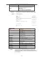
What’s the difference between ATM based
DSLAM and IP based DSLAM?
Fig 0-1 & Fig 0-2 display the differences between traditional ATM-based
DSLAM and DAS-3248 in PPPoE application sample.
Figure 0-1 PPPoE application in Traditional ATM-based ADSL
Network
As Fig 0-1 displays, in traditional ATM-based ADSL network, the user
application information is encapsulated by ADSL CPE into ATM cells in
pre-defined VC(Virtual Channel, PVC), and then
upstream the ATM cells
to DSLAM via ADSL link. (In this example, the user information (PPPoE
encapsulated) is encapsulated by ATU-R using RFC-1483 Bridge-mode
encapsulation format.)
All the ATM cells belong to the specified VC is concentrated by the DSLAM,
and switched in the ATM network clouds, to the defined destination (ISPs
or Offices), at there the ATM cells and PPPoE frames is resolved by the
Broadband Access Server, and the user application information is
serviced.
3
D-Link DAS-3248 IP DSLAM
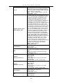
Figure 0-2 PPPoE application in DAS-3248 with Ethernet-All-The-Way Network
In addition to traditional ATM-based ADSL network. As Fig 0-2 displays,
the user application information is still encapsulated by ADSL CPE into
ATM cells in pre-defined VC (Virtual Channel, PVC), and then upstream
the ATM cells to DSLAM via ADSL link.
In the DAS-3248, all the ATM cells belong to the specified VC are
decapsulated back to the original PPPoE encapsulated Ethernet packet (if
VLAN-mode of the specified ADSL port is disabled), or mapped to the
pre-defined Ethernet-VLAN packets (if VLAN-mode of the specified ADSL
port is enabled). DAS-3248 concentrates all Ethernet-with/without
VLAN-tag packets from 48/24 ports’ ADSL and uplinks to ISP’s
Ethernet-All-The-Way network. The PPPoE frames will be resolved at
Broadband Access Server (BAS), and the user application information was
serviced.
The DAS-3248 supports ADSL CPE Bridge-mode. For future FW upgrade,
the DAS-3248 can act as BRAS to process user application information
directly.
DAS-3248 provides Ethernet-with/without VLAN tag to ATM-PVC mapping
feature for the ISP to isolate user’s data with security and to provide lots of
service enhancement capabilities. DAS-3248 supports 8 ATM PVC links
4
D-Link DAS-3248 IP DSLAM
for each ADSL/ADSL2/2+ CPE.
5
D-Link DAS-3248 IP DSLAM
1
Introduction
1.1 General
This chapter will help you understand the function and application of your
DAS-3248. It covers
DAS-3248 Overview
This section describes the overview of your DAS-3248. The DAS-3248 is
cost effective solution for you to complete immediate implementation of
multiple of services in private and public networks.
DAS-3248 Application
DAS-3248 can be applied in MTU/MDU/MHU and Ethernet-all-the-way
application.
DAS-3248 Features
This section describes the features of DAS-3248 and its specification.
6
D-Link DAS-3248 IP DSLAM
1.2 DAS-3248 Overview
Using the latest ADSL technology, DAS-3248 offers service providers a
very cost-effective solution for immediate implementation of multiple
services in private and public networks.
DAS-3248 is one product of DAS-3248 series, it acts as a standalone
IP-based DSLAM, which can concentrate and manage up to 48
ADSL/ADSL2/2+ lines. User can use local RS-232 CID and/or remote
TELNET/SNMP to manage the DAS-3248 directly
Since the ATM backbone coverage is not so general in the real broadband
network environment. Instead of traditional DSLAM system provides ATM
uplink interface, the DAS-3248 concentrates 48 ports of the ATM over
ADSL traffic which is encapsulated by ADSL CPEs, and maps each user’s
ata encapsulated in ATM-PVC to Ethernet-with/without VLAN-tag packet
(depends on the VLAN was enabled or not for the specified ATM ports),
and then uplink to Telco or ISP directly, User can enable VLAN-PVC
mapping capability for each ADSL/ADSL2/2+ port independently. The
DAS-3248 acts as bridge for the ADSL/ADSL2/2+ ports without enabling
the VLAN-PVC mapping feature. DAS-3248 provides both Ethernet-VLAN
and non-VLAN to ATM-PVC mapping feature and bridge mode for the ISP
to isolate user’s data with security and to provide lots of service
enhancement capabilities. DAS-3248 supports 8 ATM PVC links for each
ADSL/ADSL2/2+ CPE.
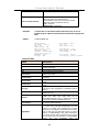
CID
Fast
Ethernet
uplink
The LED
Identification
of DAS-3248
Figure 1-1 DAS-3248 Front View
As Fig 1-1 displays, in the front view of DAS-3248, there are several LEDs
to indicate current system and link status and one replaceable
uplink/downlink module with three Giga TX/LX Ethernet interfaces for
7
D-Link DAS-3248 IP DSLAM
uplink, downlink, and local management.
Through the uplink Ethernet, the DAS-3248 can be stacked and managed
via SNMP as one entity.
As Fig 1-3 displays, in the rear-panel, there is one power adaptor, both
-42V ~ -56V DC or 90V ~ 240V AC power module can be selected. For
DAS-3248, There are two sets of DSL & POTS 50-pin Centronic
connectors. Each set provides 24-port with built-in POTS-splitter
ADSL/ADSL2/2+ module, totally 48 ADSL/ADSL2/2+ CPE users can be
supported in one DAS-3248.
4 fans in
the right
side
AC power
module
24-port ADSL
module with built-in
POTS splitter
Figure 1-2 DAS-3248 Rear View
Fig 1-3 displays the LED identification of DAS-3248, and Table-1
describes its color definition and status description.
Figure 1-3 DAS-3248 LED Identification
Table 1-1 DAS-3248 LED Description
<LED ID>
Color
POWER
MAINT
ALARM
MASTER
Green
Yellow
Red
Green
100/Act
Green/
Blinking
Green/
Blinking
Green/
Blinking
Green/
1000/ACT
GIGA
ACT
Description
Lit when power on.
Lit when maintance commands were issued.
Lit when MJ/MN events happen.
Lit when system was acted as management master
for stacking application (future feature).
Blink when information is transmitted through
100Mbps MGNT Ethernet interface.
Blink when information is transmitted through 1000
Mbps uplink Ethernet interface.
Blink when information is transmitted through
1000FX uplink Ethernet interface.
Giga uplink is activated.
8
D-Link DAS-3248 IP DSLAM
ADSL1 –
ADSL48
Blinking
Green/
Orange/
No Light
Red
Lit Solid Green when ADSL link is in active state;
when the specified ADSL link is in connection
training state;
LED off when ADSL link is not in service
Lit Red when loss of signal occurs.
Note: Do not power off your DAS-3248 when LEDs “MAINT”,
“ALARM” and “FAULT” are blinking simultaneously.
The replaceable 10/100/1000BaseT or FX uplink/subtend module design
provides the flexibility of the network implementation. Up to 8 IP DSLAMs
can be cascaded and managed as one unit
LAN Side (Uplink or Extension Side)
1*1000BaseT-MGNT + 2*1000BaseT
1*1000BaseT-MGNT+1*1000BaseT+
1*1000Fx(SX/LX)
9
D-Link DAS-3248 IP DSLAM
1.3 DAS-3248 Application
As the following figure shown, DAS-3248 provides 48 ADSL/ADSL2/2+
ports with built-in POTS splitters so that it provides broadband data service
over existing copper wires without affecting the conventional voice service.
DAS-3248, therefore, is a perfect solution for both central office co-location
and MTU/MHU markets.
10
D-Link DAS-3248 IP DSLAM
1.4 DAS-3248 Features
1.4.1 Cost Saving Solution for SMB
48/24 ports ADSL/ADSL2/ADSL2+ Subscriber Interface
10/100/1000BaseT or Fx Uplink/Subtend Interface (module selectable)
Build in POTS Splitter
Subtending capability allows up to 8 units to be cascaded and managed as
one unit
1.4.2 Excellent Management with Security
Microsoft NT/SNMP-based GUI EMS
Local RS-232 CLI, and Ethernet SNMP/TELNET management
Remote in-band SNMP/TELNET management
3-level user priviledge for system management
SNMP v1, v2c, v3
Firmware upload/download via FTP or TFTP
1.4.3 Advanced Function for Broadband Service Offering
IGMP snooping
Support up to 8 VCs, 128 MAC address per xDSL ports
Support up to 64*128 MAC address & 2K Multicast MAC address per
DAS-3248 system
Support 512 VLAN(any value in 4096)
11
D-Link DAS-3248 IP DSLAM
Support Static VLAN and Port-based VLAN
Configurable packet size (64 to 1536)
Security : VLAN filtering, MAC Filtering, IP Filtering, Access Control List by
MAC and IP address
Spanning Tree (802.1d) compliant
Traffic prioritization (802.1p)
Rate limiting by MAC and IP address
uplink Aggregation (802.3ad)
Future(SW upgrade) BRAS support 802.1x, DHCP Server & Relay,
PPPoE,
MPLS, VLAN-based VPN,
12
L3 router feature, L2TP
D-Link DAS-3248 IP DSLAM
1.5 DAS-3248 Specifications
System Architecture
ADSL/ADSL2/ADSL2+ Interface
48 (DAS-3248) ports
ADSL/ADSL2/ADS2+/SHDSL subscriber
interface with built-in POTS Splitter
One 1000BaseT MGNT+ Two 1000BaseT
or one Giga LX Uplink/Subtend Interface
(module selectable)
Subtending capability allows up to 8 units to
be cascaded and managed as one unit
Telco-50 pin Centronic connector for
ADSL+POTS IN and POTS OUT
Downstream DMT data rate from 32
kb/s up to 25 Mb/s; Upstream DMT
data rate from 32 kb/s to 1 Mb/s
Comply with ITU G.992.1 (G.DMT),;
G.DMT.bis; ITU G.992.2 (G.Lite); ANSI
T1.413 issue 2; ITU G.994.1
(G.handshake) for ADSL, G.992.3 for
ADSL2, and G.992.5 for ADSL2+
Extended power management
capabilities to optimize power
consumption for each application
Maximum reach exceeding
20Kft(6.1Km)
Protocol Handling Capability
Management
8 VCs per xDSL ports
128 MAC address per xDSL ports
64*128 MAC address
2K Multicast MAC address
512 VLAN(any value in 4096) support
Configurable packet size (64 to 1542)
Microsoft NT/SNMP-based GUI
EMS
Local RS-232 CLI, and Ethernet
SNMP/TELNET management
Remote in-band SNMP/TELNET
management
Firmware upload/download via FTP
or TFTP
SNMP v1, v2c, v3
LAN Side (Uplink or Extension Side)
1* 1000BaseT-MGNT + 2*1000BaseT
1*1000BaseT-MGNT+1*1000BaseT+
1*1000Fx(SX/LX/LH/ZX)
ATM MIBs
Private MIBs
RFC 1514, 2515 DEFINITIONS OF
MANAGED OBJECTS FOR ATM
MANAGEMENT
ANY SPECIFIC PRIVATE TRAPS
Physical condition
Protocol
Dimension:
400mm(D)x440mm(W)x44mm(H)
Weight: 6.8kg
STP; IGMP snooping; GMRP;
GVRP; LACP; LACP marker;
SNMP/UDP/IP/MAC/Ethernet
Power
Operating Environment
AC Power: auto ranging 90~240 VAC,
50-60 Hz, IEC connector
DC Power: -42~-56 VDC
Power Consumption: 150 watts
Operating Temperature: 0°~50 °C,
32°~122 °F
Storage Temperature: -30c°~70 °C,
-22°~158 °F
Humidity: 5% to 90% RH
non-condensing
Ordering information
Main
Product
Modules
DAS-3248
48 port IP DSLAM
DAS-32MGS
DAS-32MGL
1000BaseSX Module
1000BaseLX Module
13
D-Link DAS-3248 IP DSLAM
DAS-32MGT
1000BaseT Module
14
D-Link DAS-3248 IP DSLAM
2
2.1
Getting Started
General
This chapter provides the installation instruction for the hardware
installation and system configuration of your DAS-3248 so that you can
start up quickly. It includes the following sections:
Unpacking your DAS-3248
This section describes how to unpacking your DAS-3248, and part number
explanation.
Hardware Installation
This section describes the power connection, loop connection and CID
connection.
Ways of management connection
This section describes how to engage in management connection by CLI
and Telnet.
15
D-Link DAS-3248 IP DSLAM
2.2 Unpacking your DAS-3248
This section describes how to unpack your DAS-3248. For a box of
DAS-3248, there may contain the following materials:
1. DAS-3248
2. Mounting bracket package
3. RJ-45 Ethernet cable
4. Power cord (AC power module only)
5. RS 232 cable to facilitate the connection between CID and PC
6. CD including user manaul and Quick Start Guide
7. A copy of Quick Start Guide
8. Accessory package
Any other accessories requested at time of ordering.
Check the contents of the package and inspect the unit for any signs of
damage. Report any defect to vendor’s customer service representative.
Retain all packing materials for future shipment.
16
D-Link DAS-3248 IP DSLAM
2.3 Hardware Installation
The DAS-3248 can be installed in a standard 19-inch rack, by using the
mounting brackets provided.
Mount the shelf on the rack using the large screws provided.
Follows the following procedures to connect and wire the system.
2.3.1 Safety Instruction
The following is the safety instructions for DAS-3248 before installation:
1. Read and follows all warning notices and instructions of this user
manual.
2. The maximum recommended operating temperature for the DAS-3248
is 50ºC. Care must be taken to allow sufficient air circulation or space
between units when the DAS-3248 is installed inside a closed rack
assembly and racks should safely support the combined weight of all
DAS-3248.
3. The connections and equipment that supply power to the DAS-3248
should be capable of operating safely with the maximum power
requirements of the DAS-3248. In the event of a power overload, the
supply circuits and supply wiring should not become hazardous.
4. The AC adapter must plug in to the right supply voltage. Make sure that
the supplied AC voltage is correct and stable. If the input AC voltage is
over 10% lower than the standard may cause the DAS-3248 to
malfunction.
5. Do not allow anything to rest on the power cord of the AC adapter, and
do not locate the product where anyone can walk on the power cord.
6. Generally, when installed after the final configuration, the product must
comply with the applicable safety standards and regulatory
requirements of the country in which it is installed. If necessary, consult
17
D-Link DAS-3248 IP DSLAM
for technical support.
7. A rare condition can create a voltage potential between the earth
grounds of two or more buildings. If products installed in separate
building are interconnected, the voltage potential can cause a
hazardous condition. Consult a qualified electrical consultant to
determine whether or not this phenomenon exists and, if necessary,
implement corrective action before interconnecting the products. If the
equipment is to be used with telecommunications circuit, take the
following precautions:
Never install telephone wiring during a lightning storm.
Never install telephone jacks in wet location unless the jack is
specially designed for wet location.
Never touch uninsulated telephone wires or terminals unless
the telephone line has been disconnected at the network interface.
Use caution when installing or modifying telephone lines
(other than a cordless telephone) during an electrical storm. There
is a remote risk of electric shock from lightning.
Do not use a telephone or other equipment connected to
telephone lines to report a gas leak in the vicinity of the leak.
2.3.2 DAS-3248 Rear Panel Connection
The following figure shows the rear panel connection of DAS-3248:
18
D-Link DAS-3248 IP DSLAM
Figure 2-1 DAS-3248 Rear Panel Connection
Step 1: Ground the DAS-3248 by connecting a grounded wire
Step 2: Connect the ADSL line connector, a 50-pin centronic connector, of
DAS-3248 to CPE by using telco cable. Each line connector supports 24
ports of ADSL/ADSL2/2+ for Data path from MDF(Main Distribution
Frame).
Step 3: Connect the phone connector, a 50-pin centronic connector, of
DAS-3248 to Exchange/PBX by using telco cable. phone connector is an
optional module supporting Voice path to Exchange/PBX; it must be along
with Line Connector.
Step 4: Connect the power adapter and plug it into an outlet.
2.3.3 DAS-3248 Front Panel Connection
Connect the uplink port of DAS-3248 to internet or downlink to the other
DAS-3248 for stacking by using the RJ-45 cable. Furthermore, connect
the CID port to the management station’s CID port by using the RS-232
cable or connect the MGT port to the management station’s Ethernet
port by using RJ-45 in order to administer your DAS-3248 through CLI or
GUI EMS.
19
D-Link DAS-3248 IP DSLAM
Connect to another DAS-3248
Management
Station
Figure 2-2 DAS-3248 Front Panel Connections
Note: Please refer to Appendix A: pin assignment of telco cable, RJ-45
and RS-232 cable for those connectors’ pin assignment.
2.4 Ways of Management Connection
This section will tell you how to connect and manage your DAS-3248
through CLI and EMS.
2.4.1 EMS(Element Management System)
The Element Management System (EMS) is more user- friendly than CLI
for your configuring DAS-3248. The HTML files embedded in DAS-3248
are dynamically linked to the system’s functional command sets. You can
access a specified DAS-3248 through EMS.
Perform initial configuration procedures as follows:
1.
Click the EMS icon on the screen of autorun to install EMS into your
PC.
2.
Before you start to connect to EMS, it is necessary that your PC’s IP
and DAS-3248’s IP are in the same group. Note: DAS-3248’s default
MGNT IP is 10.90.91.91.
3.
Create management IPs into the DAS-3248 so that the authorized IP
20
D-Link DAS-3248 IP DSLAM
agent can manage DAS-3248 through EMS. Connect to DAS-3248
with RS-232 or Ethernet cable, and then write the IPs into DAS-3248
by telnet or CLI. Input the following commands sequentially:
a. create snmp comm community public
b. create snmp host ip 10.90.91. xxx community public, where
10.90.91.xxx is the IP of your PC.
c. create snmp traphost ip 10.90.91.xxx community public version v1,
where 10.90.91.xxx is the IP of your PC.
Note: if to use CLI, bits per second, data bits, parity, and flow control
should be set as 9600, 8, none and 1 respectively.
4.
Launch the EMS and then log in with the “Admin” for both user name
to enter the EMS system. Log in as
and password. Click on
usual. (User account: Admin; Password: Admin)
2.4.2 Command Line Interface (CLI)
The Command Line Interface is the most primary character based
configuration interface. Some of configurations not provided in Baliff can
be configured through CLI. You can access CLI from the terminal
emulation software.
The procedure of connecting to the CLI is as follows:
1.
Start up the terminal emulation software on the management
station.
2.
If necessary, reconfigure the terminal-emulation software to match
the switch console port settings.
Bits per second
Data bits
Parity
Stop bits
Flow control
3.
9600
8
None
1
None
Enter Admin when prompted for a user name and password. The
21
D-Link DAS-3248 IP DSLAM
DAS-3248 prompt appears when you have logged in to the
management interface successfully.
2.4.3 Telnet Client
DAS-3248 supports only one Telnet client that you can use to connect
with. Telnet provides a simple terminal emulation that allows you to see
and interact with the CLI of DAS-3248. As with any remote connection, the
network interface IP address for the DAS-3248 must be established.
22
D-Link DAS-3248 IP DSLAM
3
EMS Configuration
This Chapter describes how to install and set up the environment of EMS.
Once you finish it, a specified DAS-3248 can be managed remotely. Next
chapter will introduce how to manage the DAS-3248 through EMS.
.
3.1 EMS Functions
EMS is divided into the task-oriented functional groups as follows, which
are further described in subsequent sections.
Session: Allow you to start and to terminate a session as well as to
shutdown the system.
Logout: Allow you to terminate current session without shutting down
the system.
Exit: Allow you to shut down the system.
Tools:
Allow you to perform the following tools.
Evionmental options: alow you to define SNMP, Desktop and
Surveilance.
Territory Manager: Used to define the territory.
Agent Manager: Used to define agent IP addresses.
Telnet: alow you to login the CID screen of a specific agent IP
address.
User manager: Allow you to define a user profile, including login ID
and security level.
Windows: allow users to manage daughter windows in the EMS.
Cascade: allow users to cadcade Windows.
23
D-Link DAS-3248 IP DSLAM
Next Window: alow users to switch to next window.
Previous Window: alow users to switch to previous window.
Arrang Icons: those minimized icons will be locatd in the bottom of
EMS.
3.1.1 Installation
Hardware and Software Requirements
The following checklist provides the minimum hardware and software
required to operate EMS.
Windows NT/2000/XP
Autorun CD
133 MHz or higher CPU
2GB Hard disk with a minimum of 650 MB of free space
64 megabytes(MB) of RAM recommended minimum, more
memory generally improves responsiveness
An ethernet card.
Super VGA (800 x 600 resolution) or higher with 256 colors
CD-ROM drive
24
D-Link DAS-3248 IP DSLAM
Installing NetBailiff
1. Insert Autorun CD into CD –ROM Drive.
2. From the autorun screen, double click the EMS icon to start the
installation process.
3. The welcome window of EMS Setup appears. Click on
to
continue.
4. When the user information input window appears, enter your name and
company name respectively, and then click on
to
continue.
Note: please uninstall previous version of EMS if you want to install a new
version.
25
D-Link DAS-3248 IP DSLAM
5. When the Destination Location window appears, click the Browse button
to change the installation destination directory or simply use the default
setting “C:\Program Files\D-Link\EMS-SD1.
Then, click on
to continue,
6. When the Select Program Folder window appears, you may either
choose the default program folder, “D-Link\EMS-SD1”, or enter the
26
D-Link DAS-3248 IP DSLAM
name you prefer.
Then, click on
to continue,
7. When the Start Copying Files window appears, you can confirm your
current settings, if you are satisfied with the settings, click on
to start copying files.
8. When Setup Process Status window appears, the installation process is
27
D-Link DAS-3248 IP DSLAM
now in progress. This window displays a bar indicating the percentage
of completion for the current installation. In addition, the names of the
files being installed appear above the bar until the installation is
complete.
9. At the end of the installation process, the following “FINISH” window
presents. Simply click on
to complete setup. Now the
installation of EMS software is completed.
28
D-Link DAS-3248 IP DSLAM
10. After finishing the installation process, a shortcut of EMS is displayed
on the desktop. Click on
to activate EMS directly.
3.1.2 Un-installation of NetBailiff
1. Double click the Add/Remove Programs icon in Control Panel to run
29
D-Link DAS-3248 IP DSLAM
the un-installation procedure.
2. In Add/Remove Programs Properties dialogue box, selecting the
“EMS-SD1” folder and then click on
3. After your clicking on
to remove EMS.
, the following dialogue box then
prompts to you for confirmation. Click on
30
to continue the
D-Link DAS-3248 IP DSLAM
removal process.
4. The following window, “un-installation completion status” appears. Click
to complete the removal process when
become enable, indicating that the process is completed.
3.1.3 Starting the System
Users can activate the EMS either from Promgrame manger or clicking the
shortcut icon on the desktop. From Program Manager, choose the “D-Link”
program group in the Program Manager window. Then, choose the “EMS”
program item to launch the program.
31
D-Link DAS-3248 IP DSLAM
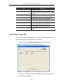
3.1.4 Logging into the System
1. Once the system is started, the Login window then prompts as follows.
2. Simply enter your user account ID and password respectively, and then
click on
to login.
If it is the very first time login as the network administrator, “Admin”
automatically presents in the “Account” field and “Password” field is
blank.
For the security concern, it is very important for you to change
your
password afterwards.
To terminate the login, simply click on
.
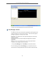
3. After launching EMS and logging in with a valid username and
password, the main window, D-Link EMS then prompts as shown in the
32
D-Link DAS-3248 IP DSLAM
following figure.
3.1.5 Terminating the System
To terminate the system at any time, simply choose the Exit command
from Session Menu. The system then terminates.
3.1.6 Logging out the Current Session
To terminate the current session, choose Logout command from Session
Menu. The user account, then, is logged out and Login window prompts for
a new login. Normally, this is used when a user wants to re-login in order to
gain a higher level of authority for certain operations.
3.2 Windows Arrangement
Users may open many daughter windows in the EMS. To benefit user’s
viewing every Window, Commands of the Windows manu is designed to
arrange daughter windows. Those commands will be inroduced
seperately.
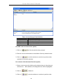
3.2.1 Cascade
Choose Cascade from Windows manu in the EMS manu bar.The cascade
33
D-Link DAS-3248 IP DSLAM
command can cascade those opened windows as follows. User can select
a window to perform operations or view status simpliy by clicking on the
title of a certain window.
3.2.2 Next Window
Next Window helps user to view next window so that it will bring the
window in the second layer to front.
3.2.3 Previous Window
Previous Window command can help user to bring the previous window to
front.
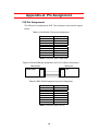
3.2.4 Arrange Icons
By slecting Arrange Icons of Windows Manu in the manu bar, it will locate
those minimized daughter windows in the bottom left of EMS window as
the following figure shown. User can select a required icon to perform EMS
management.
34
D-Link DAS-3248 IP DSLAM
3.3 Tools Menu Introduction
This chapter describes how to use tools in the EMS, including
Environmental options, Territory manager, Agent manager, user nanager
and Telnet, which are detailed in the following sections.
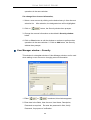
3.3.1 Environmental Options
Choose Environmental Options from Tools Menu, this Environment
daughter window then appears. By this function, user can config SNMP,
Desktop and Surveillance respectively.
SNMP Configuration
The SNMP Time-out Period and Retransmission times can be configured
as shown in the following steps:
1. Click on the TabControl (SNMP/Desktop/Surveillance) of SNMP that
will bring SNMP dialogue box to front.
2. Click on
or
to change the Time-out Period seconds and
Retransmission times.
3. Click on
to submit your changes.
35
D-Link DAS-3248 IP DSLAM
Desktop configuration
The desktop is user for setting the map of a required territory.
1. Click on the tab of Desktop that will bring Desktop dialogue box to
front, as shown in the following figure.
to quick start territory manager in which
2. Click on
users can define a dersired territory. Please refer to page 39 for more
details.
3. Click on
to load the map of a territory or click on
36
D-Link DAS-3248 IP DSLAM
to clear a loaded map. Note: the format of map is limited to
*.bmp, *.emf and *.wmf.
to submit your setting, and then the map will apply
4. Click on
to the Mounted Agent.
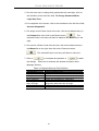
Surveillance configuration
1. Click on the tab of Surveillance that will bring the Surveillance
dialogue box to front, as shown in the following figure.
2. Click on
or
to change the mornitoring period.
3. Select the checkbox of Save expired records to save surveillance
archive, which can be browsed by clicking on the tab of Archieved
in the Event Log window as shown in the following figure:
37
D-Link DAS-3248 IP DSLAM
4.
Clicking on
to choose the directory to record
surveillance data and press
5. Click on
or
to define expired period.
to submit your settings.
38
D-Link DAS-3248 IP DSLAM
3.3.2 Territory manager configuration
Territoy manager help users to build up mornitoring territories and agents
could be categorized into different territories by users. That benefits users
to mornitor the status of PAMSPAN-2000 systems by territory. Territory
manager can be activated either from manu bar or from envoronmental
options.
Territory Manager window
Choose Territory Manager via Tools Menu, or Environmental option, and
then the Territory Management window appears.
If to add a territory to the system,
1. Click on
, the Territory Name fields then cleared to blank
for entering the data.
2. Enter Territory Name and
3. Click on
then become enable.
to apply the territoy to the system. After that,
39
D-Link DAS-3248 IP DSLAM
you can proceed to group management by Territory Management
dialog box.
4. As the following figure shown, the agent, 192.168.100.176 is
available in the territory named ALL on the left. Users can shift the
mornitoring territory from ALL to Taipei simply by selecting Taipei in
the Drop-down list on the right.
5. Choose the agent, 192.168.100.176 on the left and then click
on
. The agent IP will appear on the right and will be
mornitored under the territory, Taipei.
40
D-Link DAS-3248 IP DSLAM
6. Corresspondently, the Agent Desktop displays that Agent IP
192.168.100.176 has been moritored under the territroy, Taipei.
7. If users want to move the agent IP from Taipei to other territory,
select a desired agent IP and click on
8. Click on
to shift it to the left.
to exit the window or continue to perform
other operations in the same window.
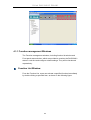
3.3.3 Agent Manager Configuration
All of the DAS-3248 agents that are to be managed by the EMS must be
“registered” to the system.
The “registeration” process is to make the
system aware of agent’s IP address and alias name.
Once an agent is
registered, it is put into the “demount” agent pool, which is still “inactive” for
the network monitor. You then have to activate it if you want it to be
monitored. An active agent can also be deactivated from the monitor for
certain operational purpose when necessary. Agent Manager is designed
for you to perform these operations.
41
D-Link DAS-3248 IP DSLAM
Agent Manager window
Choose Agent Manager from Tools Menu, this window then appears.
As mentioned above, Agent Manager is used to define the DAS-3248
agent’s IP address and community string that are to be used in the system,
and to activate the system’s monitoring of an agent; to deactivate an agent
from the system’s monitoring.
If to add an agent to the system,
1. Select a territory that a new agent belongs to. Users can click on
to activate territory manager.
2. Click on
, the data fields then cleared to blank for entering
the data. Enter values in fields, IP Address, Alias Name and
Description. The Apply buttons to the left of these fields then become
enable.
3. Click on
to apply the agent to the system.
4. If to activate (so-called “Mount”) the system’s monitoring of an agent,
click on the required agent entry in the Demount agent list, then click
42
D-Link DAS-3248 IP DSLAM
on
. The agent will appear on the Mount agent list on the
right.
5. Click on
to exit the window or continue to perform other
operations in the same window.
If to remove an agent from the system,
1. Click the required agent in the Demount agent list, and then click
on
. The agent will disappear.
2. Click on
to exit the window or continue to perform other
operations in the same window.
If to change the information of an agent,
1. Select the required agent in the Demount agent list. The information of
the selected agent will then presented on the data fields.
2. Click on
then
to Change IP, Alias Name, and Description and
becomes enable.
3. Click on
to apply the change to the system.
4. Click on
to exit the window.
Note: user can only change alias and description of the agent in the Mount
agent list and changing IP is prohibited.
If to activate the system’s monitoring of an agent,
1. Select the required agent in the Demount agent list, and then click on
the Mount button
2. Click on
. The agent will appear on the Mount agent list.
to exit the window or continue to perform other
operations in the same window.
If to de-activate the system’s monitoring of an agent,
43
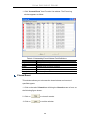
D-Link DAS-3248 IP DSLAM
1. Select the required agent in the Mount agent list, and then click on the
Demount button
. The agent will then disappears from the Mount
agent list and appears on the Demount agent list on the left.
2. Click on
to exit the window.
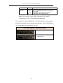
Table 3-1 Agent Management Field Definition
Field
Definition
IP Address
***.***.***.***
Alias name
Name of DAS-3248
Description
Note
Agent Desktop (Network Monitor)
Agent Desktop (see below) is the main window for the network
administrators in performing their day-to-day network monitoring jobs.
Like the standard desktop of MS Windows, Agent Desktop appears at all
time once the system is started.
First appears on the Agent Desktop is
the status of agents by an array of colors.
By which you may monitor the
status of agents, and judge if they are normal or in situations of alarms.
You may then double click on the required agent IP to activate the event
log window. Similarly, the Mounted Agents Desktop can be started up by
double clicking on the icon of territory.
to refresh the status of all agents.
In the Agents Desktop, press
44
D-Link DAS-3248 IP DSLAM
Overall status
of territory by
priority
Overall status
of Agents by
priority
Legends
Gray icon indicates that the agent is disconnected.
Green icon indicates that the agent is in normal condition.
Red icon indicates that “Major Alarm” is occurred to the agent and
requires network administrator’s attention. Network administrator
pays attention to alarms by looking into the alarms using Event
Log –
Outstanding.
Yellow icon: The red icon will turn into a yellow icon after the
network administrator has looked into the alarms. However, this
does not
mean the situation is released. If any new alarm happen, yellow
will
turn red.
Black icon indicated that the agent is demounted.
Note: the priority of colors: Gray>red>yellow>green>black
45
D-Link DAS-3248 IP DSLAM
3.3.4 Mounted Agent Desktop
Mounted agent desktop provides users with flexibity in viewing your
network using graphical presentation of network elements. Mounted agent
desktop can be easily activated by double clicking the icon of territory in
the agent desktop and apprears promptly as shown in the the following
figure. By the mounted agent desktop, the location of agents and overall
network status of a specific territory is presented.
Legends:
: This icon can be moved to where the agent is located in the map.
In addition, its color also changes with the status of the agent. For example,
the icon in red means that alarm is occurred to the agent and requires
network administrator’s attention.
3.3.5 Telnet
Users can use the Telnet to connect to a specific DAS-3248, and then
monitor and interact with the system.
46
D-Link DAS-3248 IP DSLAM
How to activate Telnet from Agent Desktop?
1. Select an agent IP in the Agent desktop.
2. Click on the right bottun of mouse and then select Telnet or
3. Choose Telnet from tool manu in the EMS window’s manu bar. Then
Telnet screen will come up immdeiately.
47
D-Link DAS-3248 IP DSLAM
4. Enter user name and password to access the CID screen.
User Manager window
The EMS for D-Link uses user accounts, password as well as power level
(system privileges) to control access and log in. There are three types of
privileges, Supervisor, Constructor and Tester.
Supervisor: The highest level. User with this privilige can access ANY
functions and data;
Constructor: User can set and modify the configuration of network
equipments.
Tester: user can run maintenance test, such as loop back function.
To perform user manager, proceed as follows,
1. Choose User Manager from Tools Menu to access this window.
From the following window, User Manager, you can add and remove
users as well as change passwords, which are used to control the login.
48
D-Link DAS-3248 IP DSLAM
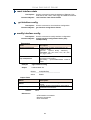
Table 3-2 User Manager Field Definition
Field
Definition
User Account
an ID to be used for login
User Name
The full name of a user
Description
Remarks for note purpose
Power Level
Privileges; Administrator and tester
If to add a user account to the system,
1. Click on
, the Security window then prompts.
2. Enter the account information as described in Security window below.
3. Click on
to exit the window or continue to perform other
operations in the same window.
If to remove a User Account from the system,
1. Select a user account by clicking on the desired entry in User Account
selection list.
After selection, the designated one will be highlighted.
2. Click on
to delete it.
3. Click on
to exit the window or continue to perform other
49
D-Link DAS-3248 IP DSLAM
operations in the same window.
If to change User Account Information,
1. Select a user account by clicking on the desired entry in User Account
selection list.
After selection, the designated one will be highlighted.
2. Click on
button, the Security window then prompts.
3. Change the account information as described in Security window
below.
4. Click on Close button to exit the window or continue to perform other
operations in the same window. 2. Click on Add button, the Security
window then prompts.
User Manager window -- Security
This window is a daughter window of User Manager window, and is used
when adding a user account or changing account information.
1. Either
or
is selected, this window appears.
2. Enter data in the fields, User Account, User Name, Description,
Password as required.
Re-enter the password in field, Verify
Password, for purpose of verification.
50
D-Link DAS-3248 IP DSLAM
3. If to force the user to change their password at the next login, click on
the checkbox to the left of the field, To Change Password When
Login Next Time.
4. If to suspend a user account, click on the checkbox to the left of the field,
Account Suspended.
5. If to assign a new Power Level to the user, click on the desired entry in
the Demount list, then click on the Mount button,
.
The
selected Power Level entry will then be added to the Mount list on the
right.
6. If to remove a Power Level from the user, click on the desired entry in
the Mount list on the right, then click on the Demount button,
.
The selected Power Level entry will then be removed.
to complete the operation or
7. Click on
the change.
to abort
Either one is selected; the window is exited to User
Manager Window.
Table 3-3 Register-Security Field Definition
Field
User Account
User Name
Description
Password
Verify Password
To change password
when next login
Account Suspended
Power Level
Definition
An ID to be used for login
The full name of a user
Remark for note purpose
Any character string, including blank
Re-enter the password as a confirmation
If this is checked, the associated user needs to
change their password at the next login.
Suspend the account.
Privileges; Administrator and tester
51
D-Link DAS-3248 IP DSLAM
4
Manage the DAS-3248
After successfully setting up the environment of EMS, you can manage
different DAS-3248 via your EMS remotely. This chapter will tell you how
to interact with a specified DAS-3248.
4.1 Activate Function Management Windows
Via EMS, users can remotely morniter the current status of a specified
DAS-3216, and then proceed advanced configuration. To activate the
function management windows, choose a specified agent that you want to
manage, and then double click the agnet, or click the right button of the
mouse to select Function List, as shown in the following figure.,
After that, the function management windows, including Function List
window and Front panel status window, will prompt as shown in the
following figure.
52
D-Link DAS-3248 IP DSLAM
4.1.1 Function management Windows
The Function management windows, including function list window and
Front panel ststus window, which are provided to mornitor the DAS-3248’s
status in real time and configure related settings. They will be introduced
repectatively.
Function List Window:
From the Function List, users can activate a specified function immediately
by double clicking a specified item, as shown in the following figure.
53
D-Link DAS-3248 IP DSLAM
Front Panel Status Window
After choosing a speicified agent, the Freont Panel Status Window,
together with the Function List Winddow, will come out immediately to
present the current status of front panel of the DAS-3248. As to the
identification of front panel, refer to page 6 to get more information.
4.2 Default Setting
This section describes how to get the information of the default setting of
the DAS-3248.
1. Click on “Default Setting” from the Function List window.
The Default Setting window appears as follows:
54
D-Link DAS-3248 IP DSLAM
In the default setting window, the status of, IP, System, VCC connection,
DSL line profile and Alarm profile are displayed clearly. How to modify
them will be introduced in the following sections.
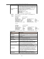
4.3 System Information
This section describes how to get and input the information of the
DAS-3248.
1. Double Click on “System Information” from the Function List Window.
The System Information window appears as follows:
2.
Input necessary information on those fields.
55
D-Link DAS-3248 IP DSLAM
Table 4-1 Sysinfo field definition
Field
Name
Location
Contact
Vendor
Object ID
DST
UpTime
HwVersion
CPSwVersion
Log Threshold
Time Zone
Definition
Alias name of the DAS-3248
Location of the DAS-3248
The contact person of the DAS-3248
The vendor of the DAS-3248
Vendor ID
This specifies if the Daylight Savings Time has been
enabled or not.
True:on
False: off
System up time
Hardware version of the DAS-3248.
Control plant version
This specifies the severity level of the trap equal to or
lower than that shall be logged. 0 represents log
threshold is diable. 1 is the lowest and represents
critical traps.
Valid values: 0-4
Time zone
Valid values: Given below, are the valid values,
followed by their descriptions.
IDLW - International Date Line West
NT - Nome
HST - Hawaii Standard
CAT - Central Alaska
AHST- Alaska-Hawaii Standard
YST - Yukon Standard
PST- US Pacific Standard
MST- US Mountain Standard
CST- US Central Standard
EST- US Eastern Standard
AST- Atlantic Standard
NFST- Newfoundland Standard
NFT- Newfoundland
BRST-Brazil Standard
AT- Azores
WAT - West Africa
GMT - Greenwich Mean
UTC - Universal (Coordinated)
WET - Western European
CET - Central European
FWT - French Winter
MET - Middle European
MEWT - Middle European Winter
SWT - Swedish Winter
EET - Eastern Europe, Russia Zone 1
IST - Israeli Standard
BT - Baghdad, Russia Zone 2
IT - Iran
ZP4 - "Russia Zone 3"
ZP5 - "Russia Zone 4"
INST - "Indian Standard"
ZP6 - "Russia Zone 5"
NST - "North Sumatra"
WAST - West Australian Standard
SSMT - South Sumatra, Russia Zone 6
JT- Java
56
D-Link DAS-3248 IP DSLAM
CCT - China Coast, Russia Zone 7
ROK - Korean Standard
KST - Korean Standard
JST - Japan Standard, Russia Zone 8
CAST - Central Australian Standard
EAST - Eastern Australian Standard
GST - Guam Standard, Russia Zone 9
IDLE - International Date Line East
NZST - New Zealand Standard
NZT - New Zealand
Example: IDLW , that stands for International Date
Line West
3. Click on
to submit your settings or
to close the
window.
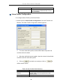
4.4 Current Event
Describes the facility for the network administrators to track and trace the
history of events happened and released. Current Event window can be
activated from Function list window.
There are three daughter windows provided to accomplish above tasks:
Outstanding Event: Allow you to view the outstanding events or status
and system information.
Closed Event: Allow you to trace events or status that are already
closed and are still within the surveillance period as defined in
Environment Options. It also allows you to view the system
information.
Archived: Allow you to browse the expired records.
Legends
Icons
The grade of
alarm indicated
Major Alarm
Minor Alarm
Abbreviation
Icons after the alarm has
been viewed.
MJ
MN
Outstanding Event
This window allows you to view the outstanding events of specific agents.
If to view the event log of a specific agent,
57
D-Link DAS-3248 IP DSLAM
1. Click “Current Event” from Function List window. The Event Log
window appears as follow:
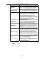
Table 4-2 Outstanding Event Window Field Definitions
Field
Description
Happen time
The date/time when the event is occurred.
Agent
The IP address of the agent associated
Grade
Severity level of event or status.
DSL
DSL Port
Site
Down stream or upstream
Description
The description of the event or status.
Closed Event
This window allows you to browse the closed alarms and events of
specified agents.
1. Click on the tab of Closed that will bring the Closed screen to front, as
the following figure shown:
2. Click on
to clear all records.
3. Click on
to exit the window.
58
D-Link DAS-3248 IP DSLAM
Table 4-3 Closed Event Window Field Definition
Field
Release Time
Others
Description
The date/time when the event is closed.
Rest of the fields is as same as described in “Outstanding
Events”.
Archived
This window allows you to browse the expired records, which can be
configured in the Evironment window.
1. Click on the tab of Archived that will bring the Archived screen to front
as follows:
59
D-Link DAS-3248 IP DSLAM
2. Click on
to clear all records.
3. Click on
to exit the window.
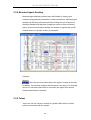
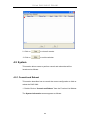
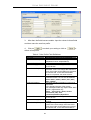
4.5 System
This section allows users to perform commit and reboot that will be
introduced as follows:
4.5.1 Commit and Reboot
This section describes how to commit the current configuration to falsh or
reboot the DAS-3248.
1. Double Click on “Commit and Reboot” from the Function List Window.
The System Information screen appears as follows:
60
D-Link DAS-3248 IP DSLAM
2. If to commit the active configuration to the flash, click on
.
3. If to reboot the system and to set the boot configuration, click on
.
4. Click on
to close the System Configuration window.
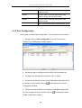
4.6 Configuration
This section describes how to configure the DAS-3248 by selecting
Configuration from Function List window. This section will cover those
functions:
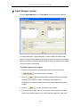
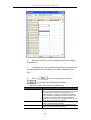
4.6.1 VLAN Configuration
Allow user to view and modify VLAN configuration. To configure VLAN,
proceed as follows:
1. Double Click on “VLAN configuration” from the Function List Window.
The VLAN configuration window appears as follows:
61
D-Link DAS-3248 IP DSLAM
2.
Select the VLAN to view or modify by using the VLAN ID
drop-down list.
3.
Use Egress PVC and Unatagged PVC drop-down list to set
the specified DSL port’s Egress PVC and Untagged PVC.
4.
to submit your settings or click on
Click on
to close the VLAN Configuration window.
Table 4-4 VLAN Configuration Field Definitions
Field
Definition
The VLAN id for this VLAN. In devices supporting "Shared
VLAN ID
Vlan for multicast" capability, the information for a multicast
mac addr is shared across vlans hence vlan id is an
optional parameter. In devices supporting "Independent
Vlan for multicast" capability each vlan can have its own
information for a multicast mac addr hence vlanid is a
mandatory parameter in all the commands other than - get.
For No Vlan case vlan id is not required.
VLAN Name
Egress PVC
Untagged PVC
Name of the VLAN
The set of ports, which are permanently assigned to the
egress list for this VLAN by management.
The set of ports, which should transmit egress packets for
this VLAN, as untagged.
62
D-Link DAS-3248 IP DSLAM
4.6.2 Ethernet Configuration
Allow user to view and modify Etherent configuration. To view or configure
Ethernet, proceed as follows:
1. Double Click on “Ethernet configuration” from the Function List
Window. The Ethernet Configuration window appears.
2. To view the Ethernet Configuration of UPLINK1 or UPLINK2 by using
the Slect Ethernet drop-down list.
3. If to modify the Ethernet Configuration, click on
first and
then proceed advanced configurations as shown in the following figure.
to submit your settings or click on
4. Click on
close the Ethernet Configuration window.
Table 4-5 Ethernet Configuration Field Definitions
Field
DHCP
Type
Definition
DHCP client enabled or disabled
Upstream or downstream
63
to
D-Link DAS-3248 IP DSLAM
Admin Status
Operation Status
IP address
Mask
Gateway
Mgmt Vlan Index
The desired state of UPLINK (enable/disable)
System is enabled or not.
IP address of the UPLINK
This specifies the network mask configured for the
UPLINK.
Gateway IP
VLAN for management traffic on this interface.
Nonzero value of this field is valid only if either 'ip'
field is non-zero or 'usedhcp' field is true. If no
Management Vlanid is specified (in the create
operation) or its value is set to zero (either in create
or modify operation) then the system shall use the
value of 'portvlanid' associated with the bridge port
created on this interface as the Management Vlan
Index. In case the management vlan (i.e.
'mgmtvlanid' or the associated 'portvlanid', if
'mgmtvlanid' is zero) doesn't exist on the system then
management shall not happen on this interface till the
corresponding VLAN is created with the Net side port
as its member.
4.6.3 Static Multicast Configuration
Allow user to view and modify Static Multicast configuration. To view or
modify Static Multicast configuration, proceed as follows:
1. Double Click on “Ethernet configuration” from the Function List
Window. The Static Multicast Configuration window appears.
64
D-Link DAS-3248 IP DSLAM
2.
Select the VLAN ID to view or modify by using the VLAN ID
drop-down list.
3.
Use Egress PVC and Forbidden Egress PVC drop-down list to
set the specified DSL port’s Egress PVC and Forbidden Egress
PVC.
4.
to submit your settings or click on
Click on
to close the VLAN Configuration window.
Table 4-6 VLAN Configuration Field Definitions
Field
Definition
The VLAN id for this VLAN. In devices supporting "Shared
VLAN ID
Vlan for multicast" capability, the information for a multicast
mac addr is shared across vlans hence vlan id is an
optional parameter. In devices supporting "Independent
Vlan for multicast" capability each vlan can have its own
information for a multicast mac addr hence vlanid is a
mandatory parameter in all the commands other than - get.
For No Vlan case vlan id is not required.
Multicast address
A multicast address is an address that designates a
group of entities within a domain.
Egress PVC
The set of ports, which are permanently assigned to the
egress list for this VLAN by managemen.
65
D-Link DAS-3248 IP DSLAM
Forbidden Egress PVC The set of ports, which should transmit egress packets for
this VLAN, as untagged.
4.7 DSL
This section describes how to configure DSL settings by selecting DSL
from Function List window. This section will cover those functions:
4.7.1 Profile Configuration
Allow users to configure Line Profile and alarm profile.
Line Profile Configuration
If to configure Line Profile, proceed as follows.
1. Double Click on “Line Profile configuration” from the Function List
Window. The Line Profile configuration window appears.
2.
To creat up a new line profile, click the DSL Name drop-down list
and then select the blank.
66
D-Link DAS-3248 IP DSLAM
3.
After that, the fields become enable. Input the values in those fields
and then name the new line profile.
4.
Click on
to submit your setting or click on
to
deliete a line profile.
Table 4-7 Line Profile Field Definitions
Field
Line Type
Transmit Rate Adaption
Definition
The ADSL line type, Fast or Interleaved
Defines what form of transmitting rate to be
adaptated, fixed or adaptAtStartup
Target Signal / Noise Margin.(0-310)
The minimum transmitting rate of ATU-C side
or ATU-R side.
Configured Signal/ Noise Margin for rate
downshift. If the noise margin falls below this
level, the modem should attempt to decrease
its transmit rate. In the case that RADSL
mode is not present, the value will be 0.
Sets the correction time for the upstream
interleaved buffer. RS can also be disabled.
Value:125us | 250us | 500us |1ms | 2ms |
4ms | disable
Preferred standard compliance. Outcome is
dependent
upon standard support of the remote
unit.GlobespanVirata High Speed ADSL DMT
(ADSL+) applications only
Value: t1413 |gLite | gDmt | alctl14
|multimode | adi | alctl
|t1413Auto|adslPlus|GspanPlus
The maximum transmitting rate of ATU-C side
or ATU-R side.
The value of Interleave Delay for this
channel.
Configured Signal/ Noise Margin for rate
upshift. If the noise margin rises above this
level, the modem should attempt to increase
its transmit rate. In the case that RADSL is
Target SNR (dB/10)
Min Tx Rate(bps)
Down Shift SNR (dB/10)
IntCorrectionUP
Preferred Standard
Maximum Transmit Rate
Interleave Delay (ms)
UP Shift SNR (dB/10)
67
D-Link DAS-3248 IP DSLAM
not present, the value will be 0.
This parameter sets the correction time for
the downstream interleaved buffer. RS can
also be disabled.
IntCorrectionDown
Alarm Profile Configuration
If to configure Alarm Profile, proceed as follows.
1. Double Click on “Alarm Profile Configuration” from the Function List
Window. The Alarm Profile Configuration window appears.
2.
To creat a new alarm profile, click the DSL Name drop-down list
and then select the blank.
3.
After that, the fields become enable. Input the values in those fields
and then name the new alarm profile.
4.
Click on
to submit your setting or click on
deliete a alarm profile.
Table 4-8 Alarm Profile Field Definitions
Field
Loss of frame within 15
minutes
Loss of signal within 15
Definition
The threshold of the number of “Loss of Frame
Seconds” within 15 minutes performance data
collection period.
The threshold of the number of “Loss of Signal
68
to
D-Link DAS-3248 IP DSLAM
minutes
Loss of link within 15
minutes
Loss of power within 15
minutes
Errored seconds
Seconds” within 15 minutes performance data
collection period.
The threshold of the number of “Loss of Link
Seconds” within 15 minutes performance data
collection period. (But only ATU-C side)
The threshold of the number of “Loss of Power
Seconds” within 15 minutes performance data
collection period.
The threshold of the number of “Errored Seconds”
within 15 minutes performance data collection period.
4.7.2 Port Configuration
Allow users to proceed port configuration. The procedures are as follows:
1. Double Click on “Port Configuration” from the Function List
Window. The fmBridgeport window appears.
2. Choose the port to configure from the DSL Port drop-down list.
3. Configure the Administration status as “Up” or “Down”.
4. Choose a Line Profile from the Line Profile Name drop-down list. If
to configure a Line Profile, Click on
to activate the Line Profile
Configuration window.
5. Choose an Alarm Profile from the Alarm Profile Name drop-down
list. If to configure an Alarm Profile, Click on
Profile Configuration window.
69
to activate the Alarm
D-Link DAS-3248 IP DSLAM
6. If necessary, modify values of a specified PVC, including VPI, VCI,
Admin Status, Learning Status, Sticky Status, Pvid, Accepted Frame
Type and Ingress Filter, and prioriy.
7. Click on
to submit your settings or click on
to close the fmBridgeport window.
Table 4-9 Port Configuration Field Definitions
Field
DSL Port
VPI
VCI
Learning Status
Sticky Status
Pvid
Accepted Frame Type
Ingress Filter
Priority
Definition
Port No. of the DAS-3248
Virtual Path Identifier
Virtual Channel Identifier
The state of learning on this bridge port. The value
enable (1) indicates that unicast Mac address
learning is enabled and the value disable indicates
that unicast Mac address learning is disabled on this
bridge port.
Indicates if the port has been set as sticky. The value
enable (1) indicates that the entries learned on this
port will not be aged out. It also indicates that the
entries learned on this port shall not be learned on
any other port. The entries learned on this port can
only be removed by management action or by
making the value as disable (2), so that the entries
can be aged out.
Port VID
Used to up/down connection.
When this is true, the device will discard incoming
frames for VLANs, which do not include this Port in its
Member set. When false, the port will accept all
incoming frames.
Optional Connection priority. No VLAN tag, no
priority.
4.8 DSL Performance Management
This section describes how to ultilize DSL Performance Management by
selecting DSL Performance Management from Function List window.
This section will cover those functions:
4.8.1 Physical Layer Info
Allow users to view the physical layer information of a specified DSL port
from the DAS-3248. The procedures are as follows:
1. Double Click on “Physical Layer Info” from the Function List
70
D-Link DAS-3248 IP DSLAM
Window. The Physical Layer Info window appears.
2. Select the port ID from the DSL Port drop-down list to view a
specified DSL’s physical Layer Info.
3. Click on
to close the window.
Table 4-10 Physical Layer Info Field Definitions
Field
SNR margin
Attenuation
Status
output power
attainable rate
ActualStandard
Bert Error
TxAtm CellCt
RxAtm CellCt
Start Progress
Definition
Noise margin value. (dB)
Difference in the total power transmitted and the total
power received by the peer atu. (db)
Current status of the ATU line. The possible values
displayed are as follows:
No defect: there are no defect on the line
los: atu-r failure due to not receiving signal
lpr: atu-r failure due to loss of signal
Total output power transmitted by atu. (dBm)
The maximum currently attainable data rate by the
atu. (kbps)
Actual standard used for connection, based on the
outcome of the negotiation with the Remote Unit.
Provides the number of bit errors detected during
BERT.
Provides Tx ATM cell counter.
Provides Rx ATM cell counter.
Defines the current detailed start up state of Xcvr.
0x0 – startup not in progress; 0x0 – 0x0FFF
Handshake/Training/ Profile Management/ Fast
Retrain in progress; 0x8000 – 0x8FFF DSP firmware
71
D-Link DAS-3248 IP DSLAM
Idle Bert Error
Idle Bert Cells
Bert Sync
Select Information Valid
Select Loop Length
Select Loop End
Select Loop Gauge
Down- Load in progress; 0xF000 – 0xFFFF illegal
Parameter
Number of bit errors.
Number of idle cells.
Indicates whether the Signal is in Sync or not.
Indicates the information validity for the SELT
operation conducted on the Xcvr.
Indicates the LOOP Length in Feet once when the
SELT information is valid on the Xcvr.
Indicates whether the loop is short or open once
when the SELT information is valid on the Xcvr.
Indicates the LOOP wire gauge information once,
when the SELT information is valid on the Xcvr.
4.8.2 Channel Layer Info
Allow users to view the Channel layer information of a specified DSL port
from the DAS-3248. The procedures are as follows:
1. Double Click on “Channel Layer Info” from the Function List
Window. The Channel Layer Info window appears.
2. Select the port ID from the DSL Port drop-down listo view a
specified DSL’s channel Layer Info.
3. Click on
to close the window.
Table 4-11 Channel Layer Information Field Definitions
Field
Interleave delay
Previous TX rate
Definition
Interleave delay for this channel. (milli-seconds)
Previous actual transmit rate on this channel if ADSL
72
D-Link DAS-3248 IP DSLAM
Current TX rate
CRC block length
Current Atm Status
Rs Symbols
Rs Depth
Rs Redundency
loop retain. (kbps)
Actual transmit rate on this channel. (kbps)
The length of the channel data-block on which the CRC
operates.
Indicates the current ATM Status.
Indicates the number of DMT symbols per
Reed-Solomon code word (S), in the downstream
direction.
Indicates interleaving depth (D), in the downstream
direction.
Indicates the number of redundant bytes (R), per
Reed-Solomon code in the downstream direction
4.8.3 Physical Layer PM
Allow users to view the Pysical layer performance of a specified DSL port
from the DAS-3248. The procedures are as follows:
1. Double Click on “Pysical Layer PM” from the Function List
Window. The Physical Layer PM window appears.
2. Press Co or RT tab to view the Pysical Layer Performance data at
down stream or up stream.
3. Click on Current to activated Current page in which users can
select Port No. to view 15 minutes and 1 Day ES, SES and UAS record.
If to retrieve the latest data, press
73
.
D-Link DAS-3248 IP DSLAM
4. Click on Previous to activate previous 15 minutes and 1 day
performance data page in which Period and Port No. are selectable.
Note: refresh button is disable in this page.
5. Click on
to clear the physical layer data.
6. Click on
to close the window.
Table 4-12 Current Phy-Layer PM Information Field Definitions
Field
Definition
CO
down stream
RT
up stream
Lofs
Number of lof failures since reset.
Loss
Number of los failures since reset.
Lols
Number of lol failures since reset.
Lprs
Number of lpr failures since reset.
Ess
Number of error seconds since reset.
Inits
Number of initialization attempts since reset. It
includes both successful and failed attempts.
Current 15-min lofs
Number of seconds in the current 15-minute
interval during which lof was detected.
Current 15-min loss
Number of seconds in the current 15-minute
interval during which los was detected.
Current 15-min lols
Number of seconds in the current 15-minute
interval during which lol was detected.
Current 15-min lprs
Number of seconds in the current 15-minute
interval during which lpr was detected.
Current 15-min ess
Number of error seconds in the current
74
D-Link DAS-3248 IP DSLAM
Field
Definition
15-minute interval.
Number of inits in the current 15-minute
interval. It includes both successful and failed
attempts.
Current 1-day time elapsed Number of seconds that have elapsed since
the beginning of the current 1-day interval.
Current 1-day lofs
Number of seconds in the current 1 day
interval during which lof was detected.
Current 1-day loss
Number of seconds in the current 1 day
interval during which los was detected.
Current 1-day lols
Number of seconds in the current 1 day
interval during which lol was detected.
Current 1-day lprs
Number of seconds in the current 1 day
interval during which lpr was detected.
Current 1-day ess
Number of error seconds in the current 1 day
interval.
Current 15-min inits
4.8.4 Channel Layer PM
Allow users to view the Channellayer performance of a specified DSL port
from the DAS-3248. The procedures are as follows:
1. Double Click on “Channel Layer PM” from the Function List
Window. The Channel Layer PM window appears.
2. Press Co or RT tab to view the Channel Layer Performance data at
down stream or up stream.
75
D-Link DAS-3248 IP DSLAM
3. Click on Current to activated Current page in which users can
select Port No. to view 15 minutes and 1 Day ES, SES and UAS record.
If to retrieve the latest data, press
.
4. Click on Previous to activate previous 15 minutes and 1 day
performance data page in which Period and Port No. are selectable.
Note: refresh button is disable in this page.
5. Click on
to clear the channel layer data.
6. Click on
to close the window.
Table 4-13 Current Channel-Layer PM Information Field Definitions
Field
Definition
CO
RT
Received blocks
down stream
up stream
The total number of blocks of data received since the
last agent reset.
Transmitted blocks
The total number of blocks of data transmitted since
the last agent reset.
Corrected blocks
Number of corrected blocks of data transmitted since
the last agent reset.
Uncorrected blocks
Number of corrected blocks of data transmitted since
the last agent reset.
Current 15-min received Number of blocks of data received during the current
blocks
15-minute interval.
Current 15-min
Number of blocks of data transmitted during the current
Transmitted blocks
15-minute interval.
Current 15-min corrected Number of corrected blocks of data transmitted during
blocks
the current 15-minute interval.
Current 15-min
Number of uncorrected blocks of data transmitted
76
D-Link DAS-3248 IP DSLAM
Field
Uncorrected blocks
current 1-day time
elapsed
Current 1-day received
blocks
Current 1-day transmitted
blocks
Current 1-day corrected
blocks
Current 1-day uncorrected
blocks
Definition
during the current 15-minute interval.
Number of seconds that have elapsed since the start of
the current day interval.
Number of blocks of data received during the current
day interval.
Number of blocks of data transmitted during the current
day interval.
Number of corrected blocks of data transmitted during
the current day interval.
Number of uncorrected blocks of data transmitted
during the current day interval.
77
D-Link DAS-3248 IP DSLAM
5
System Administration with CLI
Command Line Interface (CLI) is the primary user interface to Administrate
the system. CLI can be accessed either from the CID port or telnet session.
All CLI commands are simple strings designed for the Administrator to
manage your DAS-3248 easily.
5.1 Notation Conventions
• Keywords in a command that you must enter exactly as shown are
presented in bold italics.
User specified values in a command are presented in regular typeface,
i.e., not bold or italic.
Parameter values enclosed in < > must be specified.
Parameters enclosed in [ ] are optional. All modify parameters are
shown as optional in CLI commands even if there exists only a single
parameter.
Parameter values are separated by a vertical bar ì|î only when one of
the specified values can be used.
Parameter values are enclosed in { } when you must use one of the
values specified.
Parameters are enclosed in [ ]+ when you can specify the parameter
one or more times, in the command line.
5.2 Command Structure
There are three-level command structure used in the system. All
commands have the following general format:
<Action><Group><Sub group><Sub sub group> <tag1 value1>Ö<tagN
78
D-Link DAS-3248 IP DSLAM
valueN>
Action
This is the first keyword of a CLI command. It indicates the
type of operation to be performed.
<Group>.
"create" is an example of this keyword.
This is the second keyword of a CLI command. It indicates
the group of a CLI command.
<Sub group>.
"bridge" is an example of this keyword.
This is the third keyword of a CLI command. It indicates the
sub group of a CLI command.
"port" is an example of this keyword
<Sub sub group>. This is the fourth keyword of a CLI command. It indicates the
sub group of a CLI command.
<tag1 value1>
<tagN valueN>.
"intf" is an example of this keyword.
These are <tag value> pairs and can vary from 0 to N. They
indicate the parameter values passed to a CLI command.
"ifname aal5- 0", "portid 20", are examples of tag value pairs.
5.3 Glossary of Terms and Acronyms
Abbreviation
AAL5
ACL
ADSL
Attribute
ATM
CLI
CP
DHCP
DP
DSL
EOA
GARP
GMRP
GVRP
GARP
IGMP
Index
identifies
IP
IRL
IVL
IVM
LACP
LAN
ME
Description
ATM Adaptation Layer 5
Access Control list
Asymmetric Digital Subscriber Line
An element of an MO
Asynchronous Transmission Mode
Command Line Interface
Control Plane
Dynamic Host Configuration Protocol
Data Plane
Digital Subscriber Line
Ethernet over ATM
Generic Attribute Registration Protocol
GARP Multicast Registration Protocol
GARP VLAN Regenration Protocol
VLAN Regenration Protocol
InternetGroup Management Protocol
An element of a tabular MO that uniquely
an entry
Internet protocol
Input Rate Limiting
Individual VLAN Learning
Individual VLAN for Multicast
Link Aggregation Control Protocol
Local Area Network
Management Entity The entity, modified, controlled and
monitored through MOs.
79
D-Link DAS-3248 IP DSLAM
MO Identifier A unique number that identifies an MO.
Interpretation of the information passed to GenAg for an MO
depends upon this identifier
Managed Object Logical unit of manageable information. It is
MO
similar to a MIB. An ME is visible to the outside world in the
form of one or more MOs that constitute it.
GAG supports five operations - Create, Delete, Modify, Get,
Operations
Get-Next
ORL
Output Rate Limiting
OAM
Operations Administration and Management
RMON
Remote Monitoring
STP
Spanning Tree Protocol
SNTP
Simple Network Time Protocol
SVL
Shared VLAN Learning
SVM
Shared VLAN for Multicast
Specific Agent Entities that use GenAg interfaces to manage the system
TEA
Target Engine Agent
VC
Virtual Channel
VLAN
Virtual LAN
MO ID
5.4 CLI Command Brief Description
<action>
get
reset
modify
Create
delete
help
reset
reboot
save
logout
commit
passwd
apply
download
list
remove
upgrade
alias
unalias
prompt
Table 4-1 CLI Command - Action List
Description
Used to view information of the selected identifier and
parameters.
Used to reset a port of system.
Used to set or modify existing configuration of objects
corresponding to the identifier and parameters.
Used to create configuration of objects corresponding to the
identifier and parameters.
Used to delete configuration of objects corresponding to the
identifier and parameters. If the delete action is confirmed, the
configuration of objects will no longer exist.
Used to view the detailed usage of CLI commands.
Used to reset a port of system.
Used to restart the system.
Used to save the configuration to Flash RAM.
Used to terminate the CLI.
Used to commit the active configuration to the flash.
Used to change the password associated with a user login.
Used to apply a configuration file stored on the system
Used to download a binary, configuration or user specific file
from theremote host.
Used to list the Configuration or binary files stored on the unit
Used to remove a configuration or binary file stored on the unit
Used to upgrade a configuration or binary file stored on the
system.
Used to create an alias for any CLI command.
Used to delete an alias.
Used to set the new CLI prompt.
80
D-Link DAS-3248 IP DSLAM
<action>
traceroute
verbose
Description
Used to trace the route to the specified destination.
Using this command, a user can view the status of entries before
and after the execution of a command (create, delete, modify,
get).
5.4.1 Calling Commands
To recall commands from the history buffer, perform one of these tasks.
Command
The up arrow key
The down arrow key
Task
Recall commands in the history buffer, beginning
with the most recent command. Repeat the key
sequence to recall successively older commands.
Return to more recent commands in the history
buffer after recalling commands with “the up arrow
key”. Repeat the key sequence to recall
successively more recent commands.
81
D-Link DAS-3248 IP DSLAM
5.5 Commands Group Description
5.5.1 Interface Commands
get interface stats
Description:
Command Syntax:
Use this command to view statistics for one interface or all
the interfaces.
get interface stats [ifname interface-name ]
Parameters
Name
Description
Ifname interface-name
trap enable|disable
Example
Output
Interface name, for which configuration is to be
modified or viewed.
Type: Get
-Optional Modify - Mandatory
Valid values : eth-*,atm-*,aal5-*, eoa-*, dsl-*, dslf-*,
dsli-*, aggr-*, ehdlc-*.
Indicates whether linkUp/linkDown traps should be
generated for this interface.
Type: Modify – Optional Valid values : enable Or
disable
$ get interface stats ifname eth-0
Verbose Mode On
Output Fields
Field
Interface
Description
Type
Mtu
Bandwidth
Phy Addr
Admin Status
Description
This uniquely identifies the interface, for which information is being displayed. It may be: eth-0, eth-1,
atm- *, aal5-*, eoa-*, dsl-*, dslf-*, dsli-*, aggr-*, ehdlc-*.
This is general information about the interface
The type of interface, distinguished according the
physical/link/network protocol, immediately below
the IP layer. It may be: ATM, ETHERNET, AAL5,
EOA, DSL, FAST, INTERLEAVED, AGGR. EHDLC.
The size (in bytes) of the largest packet, which can
be sent/received on this interface in octets.
The current bandwidth of the interface, in bps.
Interface's address, at its protocol sublayer.
This is the desired state of the interface. It may be:
Up, Down.
82
D-Link DAS-3248 IP DSLAM
Operational Status
Last Change
Unknown Prot Pkts
In Octets
Out Octets
In Discards
Out Discards
In Errors
Out Errors
In Ucast Pkts
Out Ucast Pkts
HC In Octets
HC OutOctets
In Mcast Pkts
Out Mcast Pkts
In Bcast Pkts
Out Bcast Pkts
LinkUpDnTrapEnable
Promiscous Mode
Connector Present
CounterDiscontTime
This is the current operational state of the interface.
It may be: Up, Down.
Value of System UpTime (in seconds) at the time
the interface entered its current operational state.
The number of packets received via the interface,
which were discarded because of an unknown or
unsupported protocol.
The total number of octets received on the interface,
including the framing characters. For Ethernet interfaces, this will have the lower 32 bits of HC in octets.
Valid for atm-*, eoa-*, aal5-*, eth-0, eth-1, dsl-*,
dslf*, dsli-*, aggr-*.
The total number of octets transmitted out of the interface, including framing characters. For Ethernet
interfaces, this will have the lower 32 bits of HC Out
octets.
Valid for atm-*, eoa-*, aal5-*, eth-0, eth-1, dsl-*,
dslf*, dsli-*, aggr-*.
The number of inbound packets, which were
discarded, though no errors were detected.
The number of outbound packets chosen to be
discarded even though there were no errors.
The number of inbound packets, which were not
delivered to upper layers because of errors.
The number of outbound packets chosen to be
discarded because there were errors.
The number of unicast packets delivered to a higher
layer protocol.
The total number of packets requested to be sent to
unicast addresses, by upper layer protocols.
The total number of octets received on the interface,
including framing characters. This object is a
64-bit version of ifInOctets.
Valid for eth-*.
The total number of octets transmitted out of the
interface, including framing characters. This
object is a 64-bit version of ifOutOctets.
Valid for eth-*.
The number of multicast packets delivered to a
higher layer protocol.
The total number of packets requested to be sent to
multicast addresses, by upper layer protocols.
The number of broadcast packets delivered to a
higher layer protocol.
The total number of packets requested to be sent to
broadcast addresses, by upper layer protocols.
Indicates whether linkUp/ linkDown traps should be
generated for this interface.
This object has a value of false if this interface only
accepts packets/frames that are addressed to this
station. This object has a value of true when the
station accepts all packets/frames transmitted on
the media. The value true is legal only for Ethernet
interfaces. The value of PromiscuousMode does
not affect the reception of broadcast and multicast
pack-ets/frames by the interface.
This indicates whether the interface sublayer has a
physical connector or not. This is true only for physical Ethernet interfaces.
The value of sysUpTime on the most recent occasion, at which any one or more of this interface's
counters suffered a discontinuity.
83
D-Link DAS-3248 IP DSLAM
reset interface stats
Description:
Command Syntax:
Use this command to reset the statistics of Ethernet, EoA,
ATM, AAL5, DSL, DSLF, DSLI, Aggr and EHDLC interfaces.
reset interface stats ifname ifname
get interface config
Description:
Command Syntax:
Use this command to view Interface Configuration.
get interface config ifname ifname
modify interface config
Description:
Command Syntax:
Use this command to modify interface configuration.
modify interface config ifname ifname [trap
enable|disable]
Parameters
Name
Description
Ifname interface-name
Interface name, for which configuration is to be
modified or viewed.
Type: Get
-Optional Modify - Mandatory
Valid values : eth-*,atm-*,aal5-*, eoa-*, dsl-*, dslf-*,
dsli-*, aggr-*, ehdlc-*.
Indicates whether linkUp/linkDown traps should be
generated for this interface.
Type: Modify – Optional Valid values : enable Or
disable
trap enable|disable
Example
$ get interface config
Output
Verbose Mode On
IfName
LinkUp/DnTrap
---------------------------------------------------------aal5-0
Enable
Output Fields
FIELD
Description
Interface name, for which configuration is to be
viewed.
Indicates whether linkUp/linkDown traps shall be
generated for this interface.
IfName
LinkUp/DnTrap
Caution
None
References •
• ATM Interface commands
• Ethernet commands
• EoA commands
84
D-Link DAS-3248 IP DSLAM
5.5.2 ATM Interface Commands
create atm port
Description:
Command Syntax:
Use this command to create an ATM Port.
create atm port ifname interface-name lowif
dsl-portinterface-name [enable | disable] [Maxvpibits
maxvpibits][Maxvcibits maxvcibits] [Orl Orl]
delete atm port
Description:
Command Syntax:
This command is used to delete an ATM port.
delete atm port ifname interface-name
get atm port
Description:
Command Syntax:
Use this command to get information about a specific or all
ATM ports.
get atm port [ifname interface-name]
modify atm port
Description:
Command Syntax:
Parametersame
ifname interface-name
maxvc max-num-vccs
Maxvpibits max-vpi-bits
maxvcibits max-vci-bits
enable|disable
lowif dsl-portinterface-name
Use this command to enable or disable the administrative
status of ATM port.
modify atm port ifname interface-name [enable | disable]
[maxvcs maxvcs] [Maxvpibits maxvpibits]
[Maxvcibitsmaxvcibits][Orl Orl]
Description
This specifies the name of the ATM port
Type: Create - Mandatory
Delete -Mandatory
Get
- Optional
Modify -Mandatory
Valid values : atm-0 - *
This specifies the maximum number of VCCs
(PVCCs), supported at this ATM interface.
Type : Optional
Valid values :
1 -GS_CFG_MAX_ATM_VC_PER_PORT
Default Value :
GS_CFG_DEF_ATM_VC_PER_PORT
Maximum number of VPI bits configured for use at
this ATM interface.
Type : Optional
Valid values : 1 to 8.
Default Value :
Maximum number of VCI bits configured for use at
this ATM interface.
Type : Optional
Valid values : 1 to 16.
Default Value: 16.
Administrative status of the ATM port
Type : Optional
Valid values : enable or disable
Default Value: enable
This identifies the lower DSL interface, on which
this ATM interface is configured.
Type : Mandatory.
85
D-Link DAS-3248 IP DSLAM
Valid values : dsl-*
This parameter specifies the output rate limiting
val-ue in Kbps to be applied on this interface.
Type: create – Optional
Valid values :
GS_CFG_MIN_ORL_ATM_RATE_KBPS –
GS_CFG_MAX_ORL_ATM_RATE_KBPS
Orl orl
Example:
Output
$ create atm port ifname atm-0 lowif dsl-0 maxvc 4 utput
Verbose Mode On
IfName : atm-0
LowIfName :
dsl-0
MaxVccs : 4
MaxConfVccs : 0
MaxVpiBits : 9
MaxVciBits : 10
OAMSrc : 0xffffffffffffffffffffffffffffffff
ORL (kbps) : 640
Class0thrshld :
2
Class2thrshld : 2
RowStatus :
Active
UnknownVPI : 2ProfileName : gold
Class1thrshld :
3
UnknownVCI : 3
Class3thrshld : 3
Oper Status : Up
Up
Admin Status :
Output Fields
FIELD
IfName
LowIfName
Max Vccs
MaxConfVccs
MaxVpiBits
MaxVciBits
Oper Status
Admin Status
Orl (kbps)
RowStatus
UnknownVPI
UnknownVCI
Caution
Description
This specifies the name of the ATM port. It can be:
atm-0, atm-1, etc.
This specifies the name of the lower interface. It can
be: dsl-0, dsl-1 etc,.
The maximum number of VCCs (PVCCs) supported
at this ATM interface.
This specifies the current number of VCCs
configured on this port. It may be : 0 - Value
defined in MaxVccs
The maximum number of active VPI bits configured
for use at the ATM interface.
This specifies the maximum number of active VCI
bits configured for use at this ATM interface.
The actual/current state of the interface. It can be
either Up or Down
The desired state of the interface. It may either be
Up or Down
This parameter specifies the output rate limiting
value in Kbps to be applied on this interface.
This defines the row-status of the interface entry.
This parameter specifies the last seen unknown
VPI on this ATM interface.
This parameter specifies the last seen unknown
VCI on this ATM interface.
The specified lower interface should already be created. If the
parameter maxvcperport in nbsize command is modified, please
ensure that MaxConfVccs in atm port command is less than or equal
to maxvcperport.
86
D-Link DAS-3248 IP DSLAM
References
.
.
• ATM VC commands
• ATM statistics commands
• DSL commands.
5.5.3 ATM VC Commands
create atm vc intf
Description:
Command Syntax:
Use this command to create a new ATM Virtual Circuit (VC).
create atm vc intf ifname interface-name vpi vpi vci vci
lowif atm-port-interface-name [enable | disable] [aal5]
[a5txsize aal5-cpcs-tx-sdu-size] [a5rxsize
aal5-cpcs-rx-sdu-size] [vcmux | llcmux] [pvc] [channel
fast|interleaved] [ mgmtmode data|mgmt|DataAndMgmt|
raw]
delete atm vc intf
Description:
Command Syntax:
Use this command to delete an existing ATM Virtual Circuit
(VC).
delete atm vc intf ifname interface-name
get atm vc intf
Description:
Command Syntax:
Use this command to display information corresponding to a
single VC, or for all VCs.
get atm vc intf [ifname interface-name]
modify atm vc intf
Description:
Command Syntax:
Use this command to modify ATM VC parameters.
modify atm vc intf ifname interface-name [vpi vpi] [vci vci]
{enable | disable} [a5txsize aal5-cpcs-tx-sdu-size]
[a5rxsize aal5-cpcs-rx-sdu-size] [ mgmtmode data | mgmt|
DataAndMgmt | raw]
Parameters
Name
ifname interface-name
lowif
atm-port-interface-name
vpi vpi
Description
This specifies name of VC Interface.
Type: Create – Mandatory
Delete –
Mandatory
Get
– Optional
Modify – Mandatory
Valid values : aal5-0 - *
Interface Index of the ATM port, on which this VC
is getting configured.
Type : Mandatory
Valid values : atm-0 - *
Virtual Path Identifier. In order to modify, the VPI
value shall be the new VPI value and the admin
status of VC interface shall be disabled. Also, the
VPI and VCI valaue cannot be modified along with
admin status in one command.
Type : Create – Mandatory Modify – Optional
Valid values : 0-2^8
87
D-Link DAS-3248 IP DSLAM
vci vci
mgmtmode Data | Mgmt |
DataAndMgmt | Raw
enable|disable
aal5
a5txsize
aal5-cpcs-tx-sdu-size
a5rxsize
aal5-cpcs-rx-sdu-size
vcmux|llcmux
Pvc
Virtual Circuit Identifier. In order to modify, the VCI
value shall be the new VCI value and the admin
status of VC interface shall be disabled. Also, the
VPI and VCI valaue cannot be modified along with
admin status in one command.
Type : Create – Mandatory Modify – Optional
Valid values : 1-2^16
It denotes the Management Mode of the ATM VC.
If it is Data, then only data transmission can take
place. If it is Mgmt, then management of remote
CPE device can happen on that ATM VC and
packets on that ATM VC shall start coming to
Control Plane. In DataAndMgmt mode, data
transmission as well as remote CPE management
can happen on the same ATM VC interface. In
DataAndMgmt mode, the only acceptable value for
atmVCCAAL5EncapType is llc. In Mgmt mode,
EoA interface cannot be created on the ATM VC
and both Ethernet as well as non-ethernet packets
on that ATM VC shall be received at the Control
Plane. In DataAndMgmt mode, if EoA is created,
then only non-ethernet packets on that ATM VC
shall be received at the Control Plane. However, if
EoA is not created then all the packets on that
ATM VC shall be received at the Control Plane.
However, to configure ATM VC in DataAndMgmt
mode, a good practice is to to create ATM VC in
disable mode till EoA is created on it, to prevent
flooding at Control Plane. In order to run STP, the
mode has to be DataAndMgmt. If the mode is
RawATM(4), ATM cells are given to Control
Plane. In this mode, EoA interface can ot be
created on the ATM VC. If EoA interface is already
created on the ATM VC, its mode cannot be
changed to either Mgmt(2) or RawATM(4).
Type : Create Optional
Default value: Data
This specifies the Admin Status of the VC.
Type : Optional
Default Value: enable
This specifies the AAL type in use for this VC. The
only type of AAL supported in Columbia Packet is
AAL5.
Type: The only value to be supported is aal5.
Default value : aal5
This specifies the maximum transmit CPCS SDU
size to be used.
Type : Optional
Valid values :
1-GS_CFG_ATM_VC_MAX_RX_PDU_SIZE
Default Value:
GS_CFG_ATM_VC_DEF_TX_PDU_SIZE
This specifies the maximum receive CPCS SDU
size to be used
Type : Optional
Valid values :
1-GS_CFG_ATM_VC_MAX_TX_PDU_SIZE
Default Value:
GS_CFG_ATM_VC_DEF_TX_PDU_SIZE
This specifies the data multiplexing method to be
used over the AAL5 SSCS layer.
Type : Optional
Default Value: llcmux
This specifies the type of VC. The only value
supported is PVC.
Type : Optional
88
D-Link DAS-3248 IP DSLAM
Default Value: pvc
channel fast|interleaved
This extension specifies the type of channel, on
which the ATM VC's cells have to be
transmitted/re-ceived. 'fast' means fast channel
and 'inter' means interleaved channel.
Type : Optional
Default Value: Interleaved
Example
$ create atm vc intf ifname aal5-0 lowif atm-0 vpi 10 vci 10
enable aal5 pvc a5txsize 1536 a5rxsize 1536 llcmux mgmtmode
data
Output
Verbose Mode On
Entry Created
VC IfName : aal5-0
VPI : 10
Admin Status : Up
Aal5 Tx Size : 1536
AAL Type : AAL5
channel : Interleaved
18/06/2002::09:10:23
MgmtMode : Data
VC Type : PVC
Low IfName : atm-0
VCI : 10
Oper Status : Up
Aal5 Rx Size : 1536
AAL5 Encap : LLC Mux
Last Change :
Row Status : active
VC Topology : Point to Point
Output Fields
FIELD
Description
VC IfName
VC Interface Name. It can be : aal5-0 - *
Interface Index of the ATM port, on which this VC is
getting configured.
It is the Virtual Path Identifier.
It is the Virtual Circuit Identifier.
The actual/current state of the interface. It can be
either Up or Down
The desired state of the interface. It may be either
Up/Down.
This specifies the transmit CPCS SDU size to be
used.
This specifies the receive CPCS SDU size to be
used.
This specifies the AAL type in use for this VC. The
only type of AAL supported in Columbia Packet is
AAL5.
This specifies the data multiplexing method to be
used on the VC.
This extension specifies the type of channel, on
which the ATM VC's cells have to be
transmitted/received. ‘fast (1)' means fast channel
and 'inter(2)' means interleaved channel.
The value of sysUpTime at the time this VC entered
its current operational state.
It denotes the Management Mode of the ATM VC. If
it is Data, then only data transmission can take
place. If it is Mgmt, then management of remote
CPE device can happen on that ATM VC and packets on that ATM VC shall start coming to Control
Plane. In DataAndMgmt mode, data transmission
as well as remote CPE management can happen
on the same ATM VC interface. In DataAndMgmt
mode,
the
only
acceptable
value
for
Low IfName
VPI
VCI
Oper Status
Admin Status
Aal5 Tx Size
Aal5 Rx Size
Aal Type
Aal5 Encap
channel
Last Change
MgmtMode
89
D-Link DAS-3248 IP DSLAM
atmVCCAAL5EncapType is llc. In Mgmt mode, EoA
interface cannot be created on the ATM VC and
both Ethernet as well as non-ethernet packets on
that ATM VC shall be received at the Control Plane.
In DataAndMgmt mode, if EoA is created, then only
non-ethernet packets on that ATM VC shall be received at the Control Plane. However, if EoA is not
created then all the packets on that ATM VC shall
be received at the Control Plane. However, to
configure ATM VC in DataAndMgmt mode, a good
practice is to to create ATM VC in disable mode till
EoA is created on it, to prevent flooding at Control
Plane. In order to run STP, the mode has to be
DataAndMgmt. If the mode is RawATM(4), ATM
cells are given to Control Plane. In this mode, EoA
interface can ot be created on the ATM VC. If EoA
interface is already created on the ATM VC, its
mode cannot be changed to either Mgmt(2) or
RawATM(4).
This defines the row-status of the interface entry
This field specifies whether VC type is PVC or SVC.
This field specifies the VC connection topology
type.
RowStatus
VC Type
VC Topology
Caution
The specified lower interface should exist. Please refer to the
create atm port command.
References
.
.
.
• ATM interface commands
• ATM statistics commands
• ATM OAM commands
• ATM VC statistics commands.
5.5.4 AAL5 VC Statistics Commands
get atm aal5 stats
Description:
Command Syntax:
Use this command to get AAL5 VC statistics.
get atm aal5 stats [ifname interface-name]
Parameters
Name
Description
ifname
interface-name
This parameter specifies the interface for which information
is desired
Type: Get
-Optional
Valid values : aal5-0 - *
Example
$ get atm aal5 stats ifname aal5-0
Output
Low IfName : atm-0 VC
VPI : 0 VCI : 1
Tx Frames count : 100
Tx Bytes count : 1535
CRC Errors count : 0
IfName : aal5-0
Rx Frames count : 85
Rx Bytes count : 1200
Oversized SDU : 0
Output Fields
FIELD
Description
VC IfName
The name of the aal5 (aal5-0 etc) interface, for
90
D-Link DAS-3248 IP DSLAM
which statistics needs to be retrieved.
This specifies the ATM port name. It can be :
atm-0
This is the Virtual Port Identifier.
This is the Virtual Circuit Identifier.
The number of AAL5 CPCS PDUs transmitted
on this AAL5 VCC.
The number of AAL5 CPCS PDUs received on
this AAL5 VCC.
The number of octets contained in AAL5
CPCS PDUs received on this AAL5 VCC.
The number of octets contained in AAL5
CPCS PDUs received on this AAL5 VCC.
This specifies the number of CRC errors
encountered.
This specifies the number of oversized SDUs
received.
Low IfName
VPI
VCI
Tx Frames count
Rx Frames count
Tx Bytes count
Rx Bytes count
CRC Errors count
Oversized SDU
Caution
None.
References
• atm vc related commands
• atm port and statistics related commands
• atm vc statistics commands.
.
5.5.5 ATM VC Statistics Commands
get atm vc stats
Description:
Command Syntax:
Use this command to get statistical information about a
specific or all ATM virtual circuits.
get atm vc stats [ifname interface-name]
Parameters
Name
Description
ifname interface-name
This specifies the Virtual Circuit. If this is not specified,
then information for all VCs is displayed.
Type: Get
-Optional
Valid values : aal5-0 - *
Example
$ get atm vc stats ifname aal5-0
Output
Low IfName : atm-0 VC
VPI : 1
Total Tx Cells count : 250
CLPI 0 Rx Cells count : 10
IfName : aal5-0
VCI : 1
Total Rx Cells count : 20
Rx Pkts Rejected count : 0
Output Fields
FIELD
Description
LowIf
VPI
VCI
This specifies the ATM port name. It can be : atm-0
It is the Virtual Port Identifier.
It is the Virtual Circuit Identifier.
The name of the aal5 (aal5-0 etc) interface, for
which statistics needs to be retrieved.
The total number of valid ATM cells transmitted by
VC IfName
Total Tx Cells count
91
D-Link DAS-3248 IP DSLAM
this interface.
The total number of valid ATM cells received by this
interface.
The number of valid ATM cells received by this interface with CLP=0.
The total number of valid ATM cells discarded by
the interface.
Total Rx Cells count
CLPI 0 Rx Cells
Rx Pkts Rejected count
Caution
None
References
• Other atm vc related commands
• oam lpbk command
• atm port related commands
5.5.6 Ethernet Commands
create ethernet intf
Use this command to create a physical Ethernet
interface.
create ethernet intf ifname interface-name [ip
ip-address][mask net-mask][usedhcp true|false]
[speed{auto|100BT|1000BT}] [type
uplink|downlink][enable | disable][pkttype
Mcast|Bcast|UnknownUcast|All|None]
[orldecvalue][duplex half| full|auto][mgmtvlanid
mgmtvlanid] [priority priority]
Description:
Command Syntax:
delete ethernet intf
Use this command to delete a physical Ethernet
interface.
delete ethernet intf ifname interface-name
Description:
Command Syntax:
get ethernet intf
Description:
Use this command to get information about a particular
physical Ethernet interface, or about all the interfaces.
get ethernet intf [ifname interface-name]
Command Syntax:
Modify ethernet intf
Description:
Command Syntax:
Use this command to modify physical Ethernet interface
configuration.
modify ethernet intf ifname interface-name [enable |
disable][pkttype
Mcast|Bcast|UnknownUcast|All|None] [ip
ip-address][mask net-mask][usedhcp
true|false][speed{auto|100BT|1000BT}] [orl decvalue]
[duplex half|full|auto] [mgmtvlanid mgmtvlanid]
[priority priority]
92
D-Link DAS-3248 IP DSLAM
Parameters
Name
Description
ifname interface-name
ip ip-address
Mask net-mask
usedhcp true | false
speed {auto
1000BT}+
|100
BT|
This specifies the interface index used for the
Ethernet type of interfaces.
Type : Create – Mandatory
Delete – Mandatory
Get – Optional
Modify – Mandatory
Valid values : eth-0 - *
This specifies the network mask configured for the
interface. This is given in conjunction with IP Address configured and shall be given only if IP address has been given. This shall be removed
whenever IP Address is removed. Modify of
network mask for an Ethernet interface shall be
supported only if some IP address is configured on
the interface or 'UseDhcp' was configured to
"GS_TRUE" previously. If Usedhcp is GS_TRUE
and modify is done for this field then Usedhcp field
shall be set to GS_FALSE. Both Usedhcp and this
field shall not be specified together
Type : Create - Optional.
Modify - Optional
Valid Values: Any valid class A/B/C / Classless IP
address.
Default Value: None
This specifies the network mask configured for the
interface. This is given in conjunction with IP Address configured and shall be given only if IP address has been specified. This shall be removed
whenever IP Address is removed. Modifying network mask for an Ethernet interface shall be supported only if some IP address is configured on the
interface or 'etherUseDhcp' was configured to
"GS_TRUE" previously. If Usedhcp is GS_TRUE
and modify is done for this field then Usedhcp field
shall be set to GS_FALSE. Both Usedhcp and this
field shall not be specified together.
Type: This field is not allowed when a physical interface is specified and IP is 0.0.0.0. In all other
cases the field is mandatory.
Valid Values : 255.0.0.0 - 255.255.255.255
Default Value: None
This specifies whether a DHCP client is to be triggered to obtain an IP address for this interface. If
this is configured as GS_FALSE and IP address is
not configured, then management IP traffic will not
flow through the interface. If an IP address is
configured and modify is done for this field, then IP
address and net mask fields shall be set to Zero
(0.0.0.0). Both Usedhcp and IP address shall not
be specified together. If Iftype is slave then this
field cannot be set to GS_TRUE.
Type : Optional
Valid value : true or false
Default value: false
This specifies the port speed for the net side interfaces. Auto specifies that the interface will
deter-mine the line speed using auto-negotiation.
Type: Optional.
Valid Values: auto, 100BT, 1000BT. Default
Value: auto.
93
D-Link DAS-3248 IP DSLAM
type uplink|downink
enable|disable
Duplex auto|half|full
Pkttype
Mcast|Bcast|UnknownUcast
| All|None
Orl decvalue
mgmtvlanid mgmtvlanid
priority priority
Example
Output
This specifies the type of the Ethernet interfaces.
The uplink is towards the NET side (2 at most) and
downlink is towards the physical interface connected to the slave device. For uplink type, ip address
not be null, if usedhcp is false.
Type: Optional.
Valid Values: uplink, downlink.
Default Value: uplink.
Administrative status of the Ethernet interface.
Type : Modify - Mandatory
Valid values : enable or disable
Default value: enable
This defines the duplex mode to be used.
Type : optional
Valid values: auto, half, full
Default value: auto
This defines the packet type supported by the
interface.
etherPktTypeSupported
shall
be
configured for every Ethernet interface. By default,
all packets will be transmitted. The interface shall
not transmit any other packet type than configured.
Type: Create - optional
Modify - optional
Valid values : Mcast, Ucast, UnknownUcast, All
Default Value: All
This parameter specifies the output rate limiting
val-ue to be applied on this Interface. The unit for
the same is in Mbits/sec.
Type: Create - Optional Modify – Optional
Valid Values:
GS_CFG_MIN_ORL_ETH_RATE_MBPS
-GS_CFG_MAX_ORL_ETH_RATE_MBPS
Default Value:
GS_CFG_DEF_ORL_ETH_RATE_MBPS
VLAN for management traffic on this interface.
Nonzero value of this field is valid only if either 'ip'
field is non-zero or 'usedhcp' field is true. If no
Management Vlanid is specified (in the create
operation) or it's value is set to zero (either in
create or modify operation) then the system shall
use the value of 'portvlanid' associated with the
bridge port created on this interface as the
Management Vlan Index. In case the management
vlan (i.e. 'mgmtvlanid' or the associated 'portvlanid',
if 'mgmtvlanid' is zero) does not exist on the system
then IP based management on this management
VLAN shall not happen on the interface till the
corresponding VLAN is created with the Net side
port as its member.
Type : Create - optional Modify - optional
Valid values:
0 -GS_CFG_MAX_VLAN_ID
Priority to be set in Tagged Ethernet PDUs sent on
Management VLAN over this interface. This field is
valid only if either 'ip' field is non-zero or 'usedhcp'
field is true.
Type: Create - optional Modify - optional
Valid values: 0 -GS_CFG_MAX_MGMT_PRIO
create ethernet intf ifname eth-0 ip 192.168.1.1
mask255.255.255.0 speed 100bt class0thrshld 1 class1thrshld
2class2thrshld 1 class3thrshld 2 class4thrshld 1
class5thrshld2 class6thrshld 1 class7thrshld 2 profilename
sprofilemgmtvlanid 2 priority 2
Verbose Mode On
94
D-Link DAS-3248 IP DSLAM
Entry Created
Interface : eth-0
Type : Uplink UseDhcp : False
IP Address : 192.168.1.1 Mask :
Pkt Type : Mcast
Orl(mbps) : 100
Configured Duplex : Auto Duplex
Configured Speed : Auto
Class0thrshld : 1 Class1thrshld
Class2thrshld : 1 Class3thrshld
Class4thrshld : 1 Class5thrshld
Class6thrshld : 1 Class7thrshld
Profile Name : SPPROFILE
Mgmt VLAN Index : 2
Tagged Mgmt PDU Prio: 2
Speed : Operational Status : Down Admin
255.255.0.0
: None
:
:
:
:
2
2
2
2
Status : Up
Output Fields
FIELD
Description
If-Name
Type
The name of the interface, which has been created.
The type of Ethernet interface - uplink or downlink.
This specifies whether a DHCP client is to be
triggered to obtain an IP address for this interface. If
this is configured as GS_FALSE and etherIfIpAd
dress is not configured, then management IP traffic
will not flow through the interface. If an IP address
is configured and modify is done for this field then
tEtherIfIpAddress and tAggrIfNetMask field shall be
set to Zero (0.0.0.0). Both Usedhcp and tEtherIf Ip
Address shall not be specified together. If Iftype is
slave then this field cannot be set to GS_TRUE.
This specifies the network mask configured for the
interface. This is given in conjunction with IP
Address configured and shall be given only if IP
address has been given. This shall be removed
whenever IP Address is removed. Modify of
network mask for an Ethernet interface shall be
supported only if some IP address is configured on
the interface or 'UseDhcp' was configured to
"GS_TRUE" previously. If Usedhcp is GS_TRUE
and modify is done for this field then Usedhcp field
shall be set to GS_FALSE. Both Usedhcp and this
field shall not be specified together
This specifies the network mask configured for the
interface. This is given in conjunction with IP
Address configured and shall be given only if IP
address has been given. This shall be removed
whenever IP Address is removed.Modify of network
mask for an Ethernet interface shall be supported
only if some IP address is configured on the
interface or 'etherUseDhcp' was configured to
"GS_TRUE" previously. If Usedhcp is GS_TRUE
and modify is done for this field then Usedhcp field
shall be set to GS_FALSE. Both Usedhcp and this
field shall not be specified together.
This defines the packet type supported by the
interface. etherPktTypeSupported shall be
configured for every Ethernet interface. By default,
all packets will be transmitted. The interface shall
not transmit any other packet type than configured.
This parameter specifies the output rate limiting
value to be applied on this Interface.The units for
the same is in Mbits/sec
UseDhcp
Ip Address
Mask
pkttype
Orl
95
D-Link DAS-3248 IP DSLAM
Configured Duplex
The duplex mode to be used by the interface, as
configured by the user.
Duplex
The duplex mode used by the interface.
Configured Speed
The configured speed of the interface.
VLAN for management traffic on this interface.
Nonzero value of this field is valid only if either 'ip'
field is non-zero or 'usedhcp' field is true. If no
Management Vlanid is specified (in the create
operation) or it's value is set to zero (either in create
or modify operation) then the system shall use the
value of 'portvlanid' associated with the bridge port
created on this interface as the Management Vlan
Index. In case the management vlan (i.e.
'mgmtvlanid' or the associated 'portvlanid', if
'mgmtvlanid' is zero) does not exist on the system
then IP based management on this management
VLAN shall not happen on the interface till the
corresponding VLAN is created with the Net side
port as its member.
Priority to be set in Tagged Ethernet PDUs sent on
Management VLAN over this interface. This field is
valid only if either 'ip' field is non-zero or 'usedhcp'
field is true.
The actual speed of the interface.
The operational status of the interface.
The administrative status of the interface.
Mgmt VLAN Index
Tagged Mgmt PDU
Prio
Speed
Operational Status
Admin Status
5.5.7 EOA Commands
create eoa intf
Description:
Command Syntax:
Use this command to create an EoA interface towards the
CPE side.
create eoa intf ifname interface-name lowif
low-interfacename[pkttype {multicast |broadcast
|unknown-unicast}+ | all][fcs false |
true][enable|disable]
delete eoa intf
Description:
Command Syntax:
Use this command to delete an EoA interface.
delete eoa intf ifname interface-name
get eoa intf
Description:
Command Syntax:
Use this command to get information on a particular EoA
interface, or on all the EoAinterfaces.
get eoa intf [ifname interface-name]
modify eoa intf
.Description: Use this command to modify the properties of an eoa
Command Syntax:
interface.
modify eoa intf ifname interface-name [pkttype
{multicast|broadcast |unknown-unicast}+ | all| none]
[fcs false |true][enable|disable]
96
D-Link DAS-3248 IP DSLAM
Parameters
Name
Description
ifname interface-name
lowif
low-interface-name
pkttype
{multicast|broadcast
|unknownunicast}+|
all|none
fcs false | true
Enable|disable
Example
Output
This parameter specifies the name assigned to this interface.
Type : Create – Mandatory
Delete – Mandatory
Get – Optional
Modify – Mandatory
Valid values: eoa-0,eoa-1….
This parameter specifies the lower interface of an EoA
interface.
Type : Mandatory
Valid Values : aal5-0 - *
This defines the packet type supported by the interface.
EoAPktTypeSupported shall be configured for every CPE-side
Ethernet interface. By default, the option taken is 'ALL' and it
means that all packets will be transmitted. The value 'None'
means that normal UCast packets will be transmitted. The
interface shall not transmit any other packet type than
configured.
Type: Optional.
Valid Values : {multicast |broadcast |unknown-unicast}+| all
Default Value : all.
This specifies whether Ethernet FCS needs to be computed.
Currently only false is supported.
Type : Optional
Valid Values : false or true
Default Value: false.
Administrative status of the interface
Type : Optional
Valid values : enable or disable
Default Values: enable
$create eoa intf ifname eoa-0 lowif aal5-0 enable fcs false
Verbose Mode On
Entry Created
IfName : eoa-0 LowIfName : aal5-0
FCS : False
Pkt Type : ALL
Oper Status : Down Admin Status :
Up
Output Fields
Name
Description
IfName
LowIfName
FCS
The name of the interface that has been created.
Specifies the lower interface.
Whether FCS is true or false.
This defines the packet type supported by the interface. EoAPktTypeSupported shall be configured for
every CPE-side Ethernet interface. By default, the
option taken is 'ALL' and it means that all packets
will be transmitted. The value 'None' means that
normal UCast packets will be transmitted. The
interface shall not transmit any other packet type
than that configured.
The desired state of the interface. It may be either
Up or Down
The actual/current state of the interface. It can be
Pkt Type
Admin Status
Oper Status
97
D-Link DAS-3248 IP DSLAM
either up or down.
Caution
References
None
• Ethernet commands
• Ethernet Stats commands.
5.5.8 GVRP Port Info Commands
get gvrp port info
Description:
Command Syntax:
Use this command to get.
get gvrp port info [ portid portid ]
modify gvrp port info
Description:
Command Syntax:
Use this command to modify.
modify gvrp port info portid portid [ portvlanid portvlanid ]
[ acceptframetypes all | tagged ] [ ingressfiltering true|false ]
[ gvrpstatus enable | disable ] [ restrictedvlanreg true|false ]
Parameter
Name
portid portid
portvlanid portvlanid
acceptframetypes all | tagged
ingressfiltering true|false
gvrpstatus enable | disable
restrictedvlanreg
restrictedvlanregtrue|fa lse
Description
The bridge port id.
Type :Optional for all commands
Valid values: 1 -GS_CFG_MAX_BRIDGE_PORTS
The VLAN Identifier.
Type :Optional for all commands
Valid values: 1 - GS_CFG_MAX_VLANID
When this is Tagged, the device will discard
un-tagged frames or Priority-Tagged frames
received on this port. When this is All, untagged
frames or Priority-Tagged frames received on this
port will be accepted and assigned to the PVID for
this port.
Type:Optional for all commands
When this is true, the device will discard incoming
frames for VLANs, which do not include this Port in
its Member set. When false, the port will accept
all incoming frames.
Type : Optional for all commands
Valid values: true or false
The state of GVRP operation on this port.
Type:Optional for all commands
The state of Restricted VLAN Registration on this
port. If the value of this control is true(1), then creation of a new dynamic VLAN entry is permitted
only if there is a Static VLAN Registration Entry for
the VLAN concerned, in which, the Registrar
Administrative Control value for this port is, Normal
Registration.
Type :Optional for all commands
Valid values: true or false
98
D-Link DAS-3248 IP DSLAM
Example
Output
$ get gvrp port info
Verbose Mode On:
Output Fields
Field
Description
Port Id
Port VLAN Index
The bridge port id.
The VLAN Identifier.
When this is Tagged, the device will discard
un-tagged frames or Priority-Tagged frames
received on this port. When All, untagged frames or
Priority-Tagged frames received on this port will be
accepted and assigned to the PVID for this port.
When this is true, the device will discard incoming
frames for VLANs, which do not include this Port in
its Member set. When false, the port will accept
all incoming frames.
The state of GVRP operation on this port.
The total number of failed GVRP registrations, for
any reason, on this port.
The Source MAC Address of the last GVRP
message received on this port.
The state of Restricted VLAN Registration on this
port. If the value of this control is true(1), then
creation of a new dynamic VLAN entry is permitted
only if there is a Static VLAN Registration Entry for
the VLAN concerned, in which, the Registrar
Administrative Control value for this port is, Normal
Registration.
Accept Frame Types
Ingress Filtering
Gvrp Status
Failed Registrations
Last Pdu Origin
Restricted Vlan
Registration
Caution
References
None
• GVRP Commands
5.5.9 VLAN Static Commands
create vlan static
Description:
Command Syntax:
Use this command to create.
create vlan static vlanname vlanname vlanid vlanid
[egressports egressports|none ][ forbidegressports
forbidegressports|none ] [ untaggedports
untaggedports|none ][ bridgingmode bridgingmode]
[floodsupport enable|disable][bcastsupport
enable|disable]
modify vlan static
Description:
Command Syntax:
Use this command to modify.
modify vlan static ( vlanname vlanname | vlanid
vlanid )[egressports egressports|none ]
[forbidegressportsforbidegressports|none ]
[ untaggedports untaggedports|none ][ bridgingmode
99
D-Link DAS-3248 IP DSLAM
bridgingmode] [floodsupport
enable|disable][bcastsupport enable|disable]
delete vlan static
Description:
Command Syntax:
Use this command to delete.
delete vlan static ( vlanname vlanname | vlanid
vlanid )get vlan static
get vlan static
Description:
Command Syntax:
Use this command to delete.
get vlan static [ vlanname vlanname | vlanid vlanid ]
5.5.10 Vlan curr info Commands
get vlan curr info
Description:
Command Syntax:
Use this command to get.
get vlan curr info [ vlanid vlanid ]
Parameters
Name
Description
The VLAN identifier
vlanid vlanid
Type:
Get --Optional
Valid values: 1 - GS_CFG_MAX_VLAN_ID
Example
Output
$ get vlan curr info vlanid 45
VLAN Index
VLAN Status
Egress Ports
Untagged Ports
Bridging Mode
Flood support Status
Broadcast support Status
: 45
:1
: 24
: 24
: Residential
: enable
: enable
Output field description
Field
Description
VLAN Index
The VLAN identifier
This value indicates the status of the VLAN Port
cor-responding to this entry. other(1) - the entry is
for the default VLAN created for the system.
permanent(2) - this entry, corresponding to an entry
in dot1qVlanStaticTable, is currently in use and will
re-main so after the next reset of the device. The
port lists for this entry include ports from the
equivalent dot1qVlanStaticTable entry and ports
learnt dynam-ically. dynamic (3) - this entry is
currently in use and will remain so until removed by
GVRP. There is no static entry for this VLAN and it
will be removed when the last port leaves the
VLAN.
The set of ports, which are transmitting traffic for
this VLAN, as either tagged or untagged frames.
VLAN Status
Egress Ports
100
D-Link DAS-3248 IP DSLAM
The set of ports, which are transmitting traffic for
this VLAN as untagged frames.
The VLAN identifier
This value indicates the status of the VLAN Port
corresponding to this entry. other(1) - the entry is
for the default VLAN created for the system.
permanent(2) - this entry, corresponding to an entry
in dot1qVlanStaticTable, is currently in use and will
remain so after the next reset of the device. The
port lists for this entry include ports from the
equivalent dot1qVlanStaticTable entry and ports
learnt dynamically. dynamic(3) - this entry is
currently in use and will remain so until removed by
GVRP. There is no static entry for this VLAN and
it will be removed when the last port leaves the
VLAN.
The set of ports, which are transmitting traffic for
this VLAN, as either tagged or untagged frames.
The set of ports, which are transmitting traffic for
this VLAN as untagged frames.
This specifies the state of full bridging for the Vlan.
There can be 3 values associated with this based
on global fullBridgingStatus. These values can be
restricted bridging, unrestricted full bridging and
resi-dential bridging. The user can specify the
bridging mode for the vlan at the time of VLAN
creation or modification as one of these values;
otherwise the vlan inherits the globally set bridging
mode. The bridging modes are defined as
GS_CFG_RSTRCD_BRIDGING,
GS_CFG_UNRSTRCD_BRIDGING and
GS_CFG_RSDNTL_BRIDGING.
This tells if the flooding shall be done for unknown
unicast packets for this vlan or not. The unknown
unicast packets shall be flooded to all ports for a
vlan if global value (present in Dot1dTpInfo) is
enabled or throttle and the value per vlan is also
enabled else dropped.
Untagged Ports
VLAN Index
VLAN Status
Egress Ports
Untagged Ports
Bridging Mode
Flood support Status
Broadcast support Status
Caution
References
This tells if the broadcast shall be done for this vlan
or not. The broadcast packets shall be broadcasted
on all ports for a vlan if global value (present in
Dot1dTpInfo) and the value per vlan are both enabled else dropped.
None.
None.
5.5.11 VLAN Port Stats Commands
get vlan port stats
Description:
Command Syntax:
Use this command to get.
get vlan port stats [portid portid] [vlanid vlanid]
reset vlan port stats
Description:
Command Syntax:
Use this command to reset.
reset vlan port stats portid portid vlanid vlanid
101
D-Link DAS-3248 IP DSLAM
Parameters
Name
Description
Index of the Bridge Port
Type : Get – Optional Reset - Mandatory
Valid values:
1 -GS_CFG_MAX_BRIDGE_PORTS
The VLAN identifier.
Type : Get – Optional Reset - Mandatory
Valid values: 1 - GS_CFG_MAX_VLAN_ID
portid portid
vlanid vlanid
Output Fields
Field
Description
PortId
VLAN Index
Vlan In Frames
Vlan Out Frames
Vlan In Discards
Vlan In Overflow
Vlan Out Overflow
Index of the Bridge Port.
The VLAN identifier.
Number of valid frames received by this port.
Number of valid frames transmitted by this port.
Number of valid frames discarded by this port.
Count of Inframes counter overflow.
Count of Outframes counter overflow.
Caution
None
References
•
VLAN Commands.
5.5.12 Transparent Bridging Table Commands
modify bridge tbg info
Description:
Command Syntax:
Use this command to modify.
modify bridge tbg info [aging aging-timeout ]
[slaveaging aging-timeout][netaging aging-timeout]
[ floodsupport enable | disable | throttle] [bcastsupport
enable | disable] [mcastsupport enable | disable]
[mcastdrop enable | disable][throttlingrate
throttlingrate ] [ pollinterval pollinterval]][ dropiffdbfull
dropiffdbfull ] [ resnetlearning resnetlearning ]
get bridge tbg info
Description:
Command Syntax:
Use this command to get bridging related global
information.
get bridge tbg info
102
D-Link DAS-3248 IP DSLAM
Parameters
Name
Description
The timeout period, in seconds, for aging out dynamically
learned forwarding information from CPEs. The value 0 can be
configured when aging is to be stopped.
Optional
Type: Modify
Valid values:
Aging aging-timeout
GS_CFG_MIN_AGING_TIME –GS_CFG_MAX_AGING
_TIME
slaveaging
timeout
netaging
timeout
aging
aging
–
–
The timeout period, in seconds, for aging out dynamically
learned forwarding information learned from the slave device.
The recommended value for this is more than or equal to the
value for dot1dTpAgingTimeOut. The value 0 can be
configured when aging is to be stopped.
The timeout period, in seconds, for aging out dynamically
learned forwarding information from NET side port. This is
used only for full bridge configuration. The recommended value
of net aging timeout should be greater than that of the ìAgingî
parameter. The value 0 can be configured when aging is to be
stopped.
floodsupport
enable|disable|throttle
This is used to specify whether the unknown unicast packets
are to be flooded or not. The value ‘throttle’ specifies that
throttling using the ‘throttling rate’ and ‘polling interval’
parameters, configured by the user, shall control the flooding.
The fields ‘throttleRate’ and ‘pollInterval’ are valid only when
the floodsupport is set to ‘throttle’.The value for this is used
along with per vlan configuration for flood support , to determine if flooding has to be done for unknown unicast packet.
bcastsupport
enable|disable
This is used to specify whether the broadcasting is supported
or not. The value for this is used along with per vlan
configuration broadcast support, to determine if broadcasting
has to be done for the broadcast packet.
mcastsupport
enable|disable
mcastdrop
enable|disable
throttlingrate
throttlingrate
pollinterval
pollinterval
dropiffdbfull
edisable
nable|
Used to specify whether the multicast is supported or not.
Type : Optional
Valid Values: enable| disable
Used to specify whether the multicast packets are to be
dropped, or to be forwarded, if multicast is not supported. This
is only valid if dot1dTpMcastSupport is false.
Type : Optional
Valid Values: enable|disable
Defines the throttling Rate i.e. maximum number of
FDB lookup failures resulting in flooding per second, beyond
which, the flooding shall be throttled in the system. The value
of this field is valid only if the ìfloodsupportî parameter in the
system is set to value Throttle.
This indicates, in milliseconds, the polling interval.
User can modify the polling interval at run time. The polling
interval is defined in milliseconds with granularity of 100 ms.
This interval allows user to have finer granularity and control
over flooding in the system. The value of this field is valid only
if the floodsupport parameter is set to value Throttle.
This specifies if the frame for which learning could not be done
because of forwarding table limit being reached, is to be
dropped. If this is enabled the frame for which learning could
not be done because of limit exceeded shall be dropped, else
forwarded based on bridge forwarding logic.This being enabled
shall reduce flooding, as when a response to such a frame
from whcih learning could not be done shall come the frame
shall be flooded, as the entry for that unicast address, shall not
be found in forwarding table.
Type : Optional
Valid Values: enable or disable
Default value: GS_CFG_DEF_BRIDGE_IFFDBFULLDROP
103
D-Link DAS-3248 IP DSLAM
resnetlearning enable
| disable
This specifies if learning can be done over net side port for
residential bridging. Learning shall be done on Net port in case
of vlan with residential bridging if 'dot1dPortGsLearningStatus'
and 'dot1dTpGsResidentialNetLearning'is enabled. In case of
vlan with 'unrestricted' or 'restricted' bridging the learning is
governed only by per port configuration i.e.
'dot1dBasePortTable'. Currently the modification of this
parameter is not supported.
Type : Optional
Valid Values: enable or disable
Default value:
GS_CFG_DEF_NET_LEARNING_RSDNTL
Output Fields
Field
MacAddress
No. of Ports
Base Type
Aging TimeOut
Slaveaging TimeOut
Floodsupport
Bcastsupport
Description
The MAC address used by this bridge, when it must be
referred to, in a unique fashion. It is the address of one of
the Ethernet ports.
The maximum number of ports that can be controlled by
this bridge.
Indicates what type of bridging this bridge can perform. It is
always Transparent Bridging or STP.
The timeout period, in seconds, for aging out dynamically
learned for warding information from CPEs. The value 0
can be configured when aging is to be stopped.
The timeout period, in seconds, for aging out dynamically
learned forwarding information learned from the slave
device. The recommended value for this is more than or
equal to the value for dot1dTpAgingTimeOut. The value 0
can be configuredwhen aging is to be stopped.
This is used to specify whether the unknown unicast
packets are to be flooded or not. The value ‘throttle’
specifies that throttling using the ‘throttling rate’ and ‘polling
interval’ parameters, configured by the user, shall control
the flooding. The fields ‘throttleRate’ and ‘pollInterval’ are
valid only when the floodsupport is set to ‘throttle’.The
value for this is used along with per vlan configuration for
flood support , to determine if flooding has to be done for
unknown unicast packet.
This is used to specify whether the broadcasting is
supported or not. The value for this is used along with per
vlan configuration broadcast support, to determine if
104
D-Link DAS-3248 IP DSLAM
Mcastsupport
Mcastdrop
NetAgingTimeout
Bridging Mode
Throttling rate
Polling Interval
(milliseconds)
Drop If FDB full status
ResidentialNetLearning
broadcasting has to be done for the broadcast packet.
Used to specify whether the multicast is supported or not.
Used to specify whether the multicast packets are to be
dropped, or to be forwarded, if multicast is not supported.
This is only valid if dot1dTpMcastSupport is false.
The timeout period, in seconds, for aging out dynamically
learned for warding information from NET side port. This is
used only for full bridge configuration. The recommended
value of net aging timeout should be greater than that of
dot1dTpAgingTimeOut.
This specifies the current state of full bridging on the
bridge. The bridge can be set to residential bridging,
restricted full bridging or unrestricted full bridging. In
residential bridging, all packets from a CPE side port are
sent to Net side port without doing a lookup in the
forwarding table. In restricted full bridging there is a lookup
and a packet coming from a CPE port destined for another
CPE port is dropped. Hence CPE-CPE switching is not
permitted. In unrestricted full bridging, all traffic is
forwarded based on lookup.
Defines the throttling Rate i.e. maximum number of FDB
lookup failures resulting in flooding per second, beyond
which, the flooding shall be throttled in the system. The
value of this field is valid only if the ìflood supportî
parameter in the system is set to value Throttle.
This indicates, in milliseconds the polling interval. User can
modify the polling interval at run time. The polling interval is
defined in milliseconds with granularity of 100 ms. This
interval allows user to have finer granularity and control
over flooding in the system. The value of this field is valid
only if the ìfloodsupportî parameter is set to value Throttle.
This specifies if the frame for which learning could not be
done because of forwarding table limit being reached, is to
be dropped. If this is enabled the frame for which learning
could not be done because of limit exceeded shall be
dropped, else forwarded based on bridge forwarding
logic.This being enabled shall reduce flooding, as when a
response to such a frame from whcih learning could not be
done shall come the frame shall be flooded, as the entry for
that unicast address, shall not be found in forwarding table.
This specifies if learning can be done over net side port for
residential bridging. Learning shall be done on Net port in
case of vlan with residential bridging if
'dot1dPortGsLearningStatus' and
'dot1dTpGsResidentialNetLearning'is enabled. In case of
vlan with 'unrestricted' or 'restricted' bridging the learning is
governed only by per port configuration i.e.
'dot1dBasePortTable'. Currently the modification of this
parameter is not supported.
Caution
None
References
• Bridge Port commands
• Bridge Port stats commands
• Ethernet commands.
105
D-Link DAS-3248 IP DSLAM
5.5.13 IP Route Table Commands
create ip route
Description:
Command Syntax:
Use this command to create a routing table entry.
create ip route ip dest-ip-address gwyip
gwy-ip-address mask net-mask
delete ip route
Description:
Command Syntax:
Use this command to create a routing table entry.
create ip route ip dest-ip-address gwyip
gwy-ip-address mask net-mask
get ip route
Description:
Command Syntax:
Use this command to create a routing table entry.
create ip route ip dest-ip-address gwyip
gwy-ip-address mask net-mask
5.5.14 IP Net to Media Table Commands
create arp
Description:
Command Syntax:
Use this command to create a static entry in the ARP
Table.
create arp ip ip-address macaddr mac-address
delete arp
Description:
Command Syntax:
Use this command to delete an entry from the ARP table.
delete arp ip ip-address
get arp
Description:
Command Syntax:
Use this command to display either the full ARP table or a
single entry.
get arp [ip ip-address]
Parameters
Name
ip ip-address
macaddr mac-address
Description
IP address corresponding to the media-dependent
ìphysicalî address
Type: Mandatory
Valid values: Any valid class A/B/C IP address
The media-dependent ìphysicalî address
Type: Mandatory
Valid values: 0:0:0:0:0:1 - ff:ff:ff:ff:ff:fe
106
D-Link DAS-3248 IP DSLAM
Output Fields
FIELD
Description
This specifies the physical interface for the media. It may
be: eth-0 - *. This entry contains bridge management
information.
This defines the type of mapping in use. The value
Invalid has the effect that this entry is not used. It may
be: Static, Dynamic, Other
The media-dependent ìphysicalî address
IP address corresponding to the media-dependent
ìphysicalî address
If Name
Type
Mac Address
Ip Address
Caution
The specified interface should pre-exist. Please refer to the create
ethernet intf command.
References
• delete arp command
• get arp command
• create ethernet intf command
• ip route related commands.
5.5.15 Bridge Mode Commands
get bridge mode
Description:
Command Syntax:
Use this command to get the current bridging mode.
get bridge mode
107
D-Link DAS-3248 IP DSLAM
5.5.16 DHCP Client Commands
get dhcp client info
Description:
Command Syntax:
Use this command to get DHCP client information for clients,
on the specified interface, or for all the interfaces.
get dhcp client info [ifname interface-name]
Parameters
Name
Description
Ifname interface-namef
This specifies the interface name on which DHCP is
running. If this is not specified, then information for
clients on all such interfaces will be displayed.
Type : Optional
Valid values : eth-*, aggr-*
Output Fields
FIELD
Description
This is an interface on which DHCP is running: It can
be : eth-*, aggr-*
This specifies the address of the DHCP server with
whom the client has obtained the IP address and other
configuratio.s
This specifies the current state of the client. It may be:
Init, Selecting, Bound, Requesting, Renew or Bind.
If-Name
Server
Status
This signifies the date on which the DHCP server leased
out the IP address to the client.
Lease Start Date
Lease Time
Caution
References
This specifies the time period, (in seconds), for which an
IP address was leased out by the server.
The client is expected to renew the lease before the
expiry of this timer or release the IP Address.
None.
• dhcp client stats related commands
get dhcp client stats
Description:
Command Syntax:
Use this command to get DHCP client statistics on an
interface on which the DHCP client is running, or on all
such interfaces.
get dhcp client stats [ifname interface-name]
Parameters
FIELD
Ifname interface-name
This specifies the interface name on which DHCP is running.
If this is not specified then information for clients on all such
interfaces will be displayed.
108
D-Link DAS-3248 IP DSLAM
Type: Optional
Valid values : eth-0- *
Output Fields
FIELD
If-Name
Msgs Sent
Msgs Rcvd
Decline Sent
Offer Msgs Rcvd
Discover Msgs Sent
Req Sent
Acks Rcvd
Rel Sent
Nacks Rcvd
Inform Sent
Invalid Rcvd
Caution
References
Description
This is an interface on which DHCP is running: It
can be : eth-0
This specifies number of DHCP messages received
sent on this interface.
This specifies number of DHCP messages sent
received on this interface.
This specifies number of DHCP decline messages
sent on this interface.
This specifies number of DHCP offer messages
received on this interface.
This specifies number of DHCP discover messages
sent on this interface.
This specifies number of DHCP request messages
sent on this interface.
This specifies number of DHCP acks received on
this interface.
This specifies number of DHCP release messages
sent on this interface.
This specifies number of DHCP nacks received on
this interface.
This specifies number of DHCP inform messages
sent on this interface.
This specifies number of invalid dhcp messages
received on this interface.
None
• dhcp client info related commands
5.5.17 Multicast Forwarding Table Commands
get bridge mcast forwarding
Description:
Command Syntax:
Use this command to get.
get bridge mcast forwarding [vlanid vlanid]
[macaddressmacaddress]
Parameters
Name
Description
109
D-Link DAS-3248 IP DSLAM
vlanid vlanid
macaddress
macaddress
The VLAN id for this VLAN. In devices supporting
"Shared Vlan for multicast" capability, the information for a multicast MAC address is shared across
vlans. Hence vlan id is an optional parameter. In
de-vices supporting "Independent Vlan for
multicast" capability, each vlan can have its own
information for a multicast MAC address. Hence
vlanid is a mandatory parameter in all the
commands other than - get. For No Vlan case, vlan
id is not required.
Type: Optional
Valid values: 0 - GS_CFG_MAX_VLAN_ID
The destination Group MAC address in a frame to
which this entry's filtering information applies. Bit 0
of the first octet of mac addr indicates a group
(multicast) mac addr if the bit is SET.Eg
01:00:00:00:00:00, 03: FF: FF: FF: FF.
Type: Optional Valid values:
Output Fields
Field
Vlan Index
Mac Address
Egress Ports
Group Learnt
Caution
References
Description
The VLAN id for this VLAN. In devices supporting "Shared Vlan for
mul-ticast" capability, the information for a multicast MAC address is
shared across vlans. Hence vlan id is an optional parameter. In devices
supporting "Independent Vlan for multicast" capability, each vlan can
have its own information for a multicast MAC address. Hence vlanid is
a mandatory parameter in all the commands other than - get. For No
Vlan case, vlan id is not required.
The destination Group MAC address in a frame, to which this entry's
filtering information, applies.
The complete set of bridge ports, in this VLAN, to which frames
destined for this Group MAC address are currently being explicitly
forwarded. This does not include ports for which this address is only
implicitly forwarded, in the dot1qForwardAllPorts list.
The subset of bridge ports in EgressPorts, which were learned by
GMRP or some other dynamic mechanism, in this Filtering database.
None
• bridge static multicast
5.5.18 Bridge Static Unicast Commands
create bridge static ucast
Description: This command is used to create.
Command Syntax: create bridge static ucast [vlanid vlanid] ucastaddr
ucastaddr [portid portid]
delete bridge static ucast
Description: This command is used to delete.
Command Syntax: delete bridge static ucast [vlanid vlanid] ucastaddr
ucastaddr
110
D-Link DAS-3248 IP DSLAM
get bridge static ucast
Description: This command is used to get.
Command Syntax: get bridge static ucast [ vlanid vlanid ] [ ucastaddr
ucastaddr ]
modify bridge static ucast
Description: This command is used to modify.
Command Syntax: modify bridge static ucast [vlanid vlanid]
ucastaddrucastaddr [ portid portid ]
Parameter
Name
vlanid vlanid
ucastaddr ucastaddr
portid portid
Description
The VLAN id for this VLAN. . For No Vlan case, vlan
id is not required.
Type : Optional
Valid values: 1-GS_CFG_MAX_VLAN_ID
The Destination unicast Mac Address, to which
filtering info applies
Type: Mandatory
Valid values:
Type : Optional
Valid values: 1- GS_CFG_MAX_BRIDGE_PORT
5.5.19 Bridge Static Multicast Commands
create bridge static mcast
Description: Use this command is used to create.
Command Syntax: create bridge static mcast [vlanid vlanid] mcastaddr
mcastaddr [ egressports egressports ]
[ forbidegressports forbidegressports ]
delete bridge static mcast
Description: Use this command is used to delete.
Command Syntax: delete bridge static mcast [vlanid vlanid] mcastaddr
mcastaddr
get bridge static mcast
Description: Use this command is used to get.
Command Syntax: get bridge static mcast [ vlanid vlanid ] [ mcastaddr
mcastaddr ]
modify bridge static mcast
Description: Use this command is used to modify
Command Syntax: modify bridge static mcast [vlanid vlanid] mcastaddr
mcastaddr [ egressports egressports ]
[ forbidegressports forbidegressports ]
111
D-Link DAS-3248 IP DSLAM
Parameter
Name
Vlanid vlanid
mcastaddr
mcastaddr
egressports
egressports|none
forbidegressports
forbidegressports|
none
Description
The VLAN id for this VLAN. In devices supporting
"Shared Vlan for multicast" capability, the information
for a multicast MAC address is shared across vlans.
Hence vlan id is an optional parameter. In de-vices
supporting "Independent Vlan for multicast" capability,
each vlan can have its own information for a multicast
MAC address. Hence vlanid is a mandatory parameter
in all the commands other than - get. For No Vlan case,
vlan id is not required.
Type
:Optional for all commands
Valid values: 0 - GS_CFG_MAX_VLAN_ID
Default value:
The destination multicast MAC address in a frame, to
which this entry's filtering information applies. Bit 0 of
the first octet of the MAC address indicates a group
(multicast) MAC address, if the bit is SET. For example,
01:00:00:00:00:00,03:FF:FF:FF:FF. Addresses in the
range 01:80:C2:00:00:00 - 01:80:C2:00:00:0f and
01:80:C2:00:00:20 - 01:80:C2:00:00:2f have been
blocked as value of this index, as these are reserved
GARP addresses.
Type
: Create -- Mandatory
Modify --Mandatory
Delete -- Mandatory
Get - Optional
Default value:
The set of ports, to which frames received from a
specific port and destined for a specific Multicast MAC
address must be forwarded. A port may not be added in
this set, if it is already a member of the set of ports in
ForbidEgressPorts. More than one val-ue can be
given, separated by spaces.
Type
:Optional for all commands
Valid values: 1 – GS_CFG_MAX_BRIDGE_PORTS
Default value: none
The set of ports, to which frames received from a
specific port and destined for a specific Multicast
MACaddress must not be forwarded, regardless of any
dynamic information. A port may not be added in this
set if it is already a member of the set of ports in
EgressPorts.
Type
:Optional for all commands
Valid values : 1 – GS_CFG_MAX_BRIDGE_PORTS
Default value: none
Example
$ create bridge static mcast vlanid 7
mcastaddr 01:00:5e:00:00:01 egressports 10
forbidegressports 20
Output
Verbose Mode On:
112
D-Link DAS-3248 IP DSLAM
Output Fields
Field
Description
VLan Index
Mcast Address
Egress ports
Forbidden
Egress ports
Caution
The VLAN id for this VLAN. In devices supporting
"Shared Vlan for multicast" capability, the information for a multicast MAC address is shared across
vlans. Hence vlan id is an optional parameter. In
de-vices supporting "Independent Vlan for
multicast" capability, each vlan can have its own
information for a multicast MAC address. Hence
vlanid is a mandatory parameter in all the
commands other than - get. For No Vlan case, vlan
id is not required.
The destination multicastcast MAC address in a
frame, to which the filtering information of this entry
applies.
The set of ports, to which frames received from a
specific port and destined for a specific Multicast
MAC address must be forwarded. A port may not
be added in this set if it is already a member of the
set of ports in ForbiddenEgressPorts.
The set of ports, to which frames received from a
specific port and destined for a specific Multicast
MAC address must not be forwarded, regardless of
any dynamic information. A port may not be
added in this set if it is already a member of the set
of ports in EgressPorts.
None
5.5.20 Bridge mcast fwdunreg commands
get bridge mcast fwdunreg
Description: Use this command to get.
Command Syntax: get bridge mcast fwdunreg [ vlanid vlanid ]
modify bridge mcast fwdunreg
Description: Use this command to create.
Command Syntax: modify bridge mcast fwdunreg vlanid vlanid [egressports
egressports|none][forbidegressports forbidegressports
|none]
113
D-Link DAS-3248 IP DSLAM
Parameters
Name
Description
vlanid vlanid
The VLAN id for this VLAN. In devices supporting "Shared
Vlan for multicast" capability, the information for a
multicast MAC address is shared across VLANs. Hence,
VLAN id is an optional parameter. In devices supporting
"Independent Vlan for multicast" capability, each VLAN
can have its own information for a multicast MAC address.
Hence, VLAN id is a mandatory parameter in all the
commands other than - get. For No Vlan case, vlan id is
not required.
Type
:Modify – Optional
Get -- Optional
Valid values :0 - GS_CFG_MAX_VLAN_ID
Default value :
The set of ports configured by management,in this VLAN,
to which multicast group-addressed frames for which
there is no more specific forwarding information, are to be
forwarded. More than one value can begiven, separated
by spaces.
Type
: Modify -- Optional
Valid values: 1-386
The setofports configured bymanagementin this VLAN for
which the Service Requirement attribute Forward
Unregistered Multicast Groups may not be dynamically
registered by GMRP. More than one value can be given
separated by spaces.
Type
: Modify -- Optional
Valid values: 1-386
Egressports
egressports|none
forbidegressports
forbidegressports
|none
Example
Output
$ modify bridge mcast fwdunreg
egressports 34 forbidegressports 345
Verbose Mode On
114
vlanid
1
D-Link DAS-3248 IP DSLAM
Output Fields
Field
Description
VLAN Index
Forward
Unregistered Ports
Forward
Unregistered Static
Ports
Forward
Unregistered
Forbidden Ports
Caution
The VLAN id for this VLAN. In devices supporting
"Shared Vlan for multicast" capability, the information
for a multicast MAC address is shared across VLANs.
Hence, VLAN id is an optional parameter. In devices
supporting "Independent Vlan for multicast" capability,
each VLAN can have its own information for a
multicast MAC address. Hence, VLAN id is a
mandatory parameter in all the commands other than get. For No Vlan case, vlan id is not required
The complete set of ports in this VLAN, to which
multicast group-addressed frames for which there is
no more specific forwarding information, will be
forwarded. This includes ports, for which this need has
been determined dynamically by GMRP, or configured
statically by management.
The set of ports, configured by management, in this
VLAN, to which multicast group-addressed frames for
which there is no more specific forwarding information,
are to be forwarded. More than one value can be
given, separated by spaces.
The set of ports, configured by management in this
VLAN, for which the Service Requirement attribute
Forward Unregistered Multicast Groups, may not
be dynamically registered by GMRP. More than one
value can be given, separated by spaces.
None
5.5.21 ridge tbg traps Commands
get bridge tbg traps
Description: Use this command to get.
Command Syntax: get bridge tbg traps
modify bridge tbg traps
Description: Use this command to modify.
Command Syntax: modify bridge tbg traps [ bindingstatus enable | disable ]
Parameters
Name
Description
bindingstatus enable |disable
This allows the user to enable or disable the
generation of 'binding status changed' trap.
Type: Modify ---Optional
Example $ get bridge tbg traps
Output
Binding Status Changed Trap : enable
115
D-Link DAS-3248 IP DSLAM
Output Fields
FIELD
Description
Binding Status Changed
Trap
This allows the user to enable or disable the
generation of 'binding status changed' trap.
Caution None
5.5.22 Bridge Port Table Commands
create bridge port intf
Description: Use this command to create a new bridge port.
Command Syntax: create bridge port intf portid portid [maxucast
max-ucast-addresses ] [learning enable|disable][status
enable|disable] [stickystatus enable | disable]
[ aclglbdenyapply Enable | Disable ] [ aclglbtrackapply
Enable | Disable ]
delete bridge port intf
Description: This command is used to delete an existing bridge port.
Command Syntax: delete bridge port intf portid portid
get bridge port intf
Description: Use this command to get the information about a specific
bridge port or for all the ports.
Command Syntax: get bridge port intf [ portid portid ]
modify bridge port intf
Description: Use this command to modify bridge port extension attributes
Command Syntax: modify bridge port intf portid portid [maxucast
max-ucast-addresses ] [learning enable|disable][status
enable|disable] [stickystatus enable |
disable][ aclglbdenyapply Enable |
Disable ][ aclglbtrackapply Enable | Disable ]
Parameters
Name
portid portid
Ifname <name>
Description
The bridge port id
Type: Create --Optional
Delete --Mandatory
Modify --Mandatory
Get -- Optional
Valid values: 1 -GS_CFG_MAX_BRIDGE_PORTS
The interface name associated with the given port.
Type
: Create --Mandatory
Valid values: 1 -GS_CFG_MAX_BRIDGE_PORTS
116
D-Link DAS-3248 IP DSLAM
maxucast
max-ucast-addresses
learning
enable|disable
status enable|disable
stickystatus enable |
disable
This specifies the maximum number of unicast addresses,
which can be learned from this port. This can be modified
when the admin status of bridge port is disabled. Max of
number of unicast entries that can be learned/configured
on a bridge port on CPE side is
GS_CFG_MAX_NUM_CPE_PORT_UCAST_MAC
_ENTRIES. The default value for number of unicast
entries that can be learned or configured on a bridge port
is GS_CFG_DEF_NUM_CPE_PORT_UCAST_MAC
_ENTRIES. Max of number of unicast entries that can be
learned/configured on a bridge port on NET side is
GS_CFG_MAX_NUM_NET_PORT_UCAST_MAC
_ENTRIES. The default value for number of unicast
entries that can be learned or configured on a bridge port
is GS_CFG_DEF_NUM_NET_PORT_UCAST_MAC_
ENTRIES. Max of number of unicast entries that can be
learned/configured on a bridge port on downlink side is
GS_CFG_MAX_NUM_DNLINK_PORT_UCAST_M
AC_ENTRIES. The default value for number of unicast
entries that can be learned or configured on a bridge port
is GS_CFG_DEF_NUM_DNLINK_PORT_UCAST_M
AC_ENTRIES.
Type
: Create -- Optional
Modify -- Optional
Default value: 256
The State of Learning on this bridge port. The value
enable (1) indicates that unicast Mac address learning is
enabled and the value disable indicates that unicast Mac
address learning is disabled on this bridge port. The
default value of learning status for CPE/Downlink side
bridge ports shall be
GS_CFG_DEF_PORT_LEARNING_STATUS and for NET
side bridge port default value shall be
GS_CFG_DEF_NET_PORT_LEARNING_STATUS
Type
: Create --Optional
Modify -- Optional
Valid Values: enable or disable
Default value: Enable
The desired state of the bridge port. On creation, the
bridge port shall be created in enabled AdminStatus by
default.
Type
: Create --Optional
Modify -- Optional
Valid Values: enable or disable
Default value: disable
Indicates if the port has been set as sticky. The value
enable (1) indicates that the entries learnt on this port will
not be aged out. It also indicates that the entries learnt on
this port shall not be learnt on any other port. The entries
learnt on this port can only be removed by management
action or by making the value as disable (2) so that the
entries can be aged out.
Type : Create --Optional
Modify -- Optional
Valid Values: enable or disable
Default value: enable
117
D-Link DAS-3248 IP DSLAM
aclglbdenyapply
Enable | Disable
aclglbtrackapply
Enable | Disable
Example
This specifies whether the global acl macentry deny list
represented by MO AclGlobalMacList is to be applied to
this port or not. The default value of this parameter shall
depend on the port type. For Net side ports, the default
value shall be
GS_CFG_DEF_NET_PORT_ACL_GLB_DENY_S TATUS
and for the cpe side ports the default value shall be
GS_CFG_DEF_CPE_PORT_ACL_GLB_DENY_STATUS.
Type: Modify --Optional
This specifies whether the global acl macentry track list
represented by MO AclGlobalMacList is to be applied to
this port or not. The default value of this parameter shall
depend on the port type. For Net side ports, the default
value shall be GS_CFG_DEF_NET_PORT_ACL_GLB
_TRACK_STATUS and for the cpe side ports the default
value shall be GS_CFG_DEF_CPE_PORT_ACL_GLB_
TRACK_STATUS.
Type: Modify --Optional
$ create bridge port intf ifname eth-0 portid 10 maxucast 200
learning enable stickystatus enable enable aclglbdenyapply
Disable aclglbtrackapply Disable
Output
Entry Created
Set Done
Port Id
: 10
eth-0
Max Unicast Addresses : 200
Enable
Port Oper Status
: Disable
Disable
Sticky Status
: Enable
Disable
Acl Global Deny Apply : Disable
Acl Global Track Apply : Disable
IfName
:
Learning Status
:
Port Admin Status :
FDB Modify
Output Fields
FIELD
Description
Port Id
If Name
The bridge port identifier
The interface name associated with the given port.
118
:
D-Link DAS-3248 IP DSLAM
Max Unicast
Addresses
Learning status
Port oper status
Port admin status
Sticky Status
Acl Global Deny
Apply
This specifies the maximum number of unicast
addresses, which can be learned from this port. This
can be modified when the admin status of bridge port
is disabled. Maximum number of unicast entries that
can be learned/configured on a bridge port on CPE
side is
GS_CFG_MAX_NUM_CPE_PORT_UCAST_MAC
_ENTRIES. The default value for number of unicast
entries that can be learned or configured on a bridge
port is
GS_CFG_DEF_NUM_CPE_PORT_UCAST_MAC
_ENTRIES. Maximum number of unicast entries that
can be learned/configured on a bridge port on NET
side is
GS_CFG_MAX_NUM_NET_PORT_UCAST_MAC
_ENTRIES. The default value for number of unicast
entries that can be learned or configured on a bridge
port is
GS_CFG_DEF_NUM_NET_PORT_UCAST_MAC_
ENTRIES. Maximum number of unicast entries that
can be learned/configured on a bridge port on downlink side is
GS_CFG_MAX_NUM_DNLINK_PORT_UCAST_M
AC_ENTRIES. The default value for number of
uni-cast entries that can be learned or configured on a
bridge port is
GS_CFG_DEF_NUM_DNLINK_PORT_UCAST_M
AC_ENTRIES.
The state of learning on this bridge port. The value
enable (1) indicates that unicast Mac address learning
is enabled and the value disable indicates that unicast
Mac address learning is disabled on this bridge port.
The default value of learning status for CPE/Downlink
side bridge ports shall be
GS_CFG_DEF_PORT_LEARNING_STATUS and for
NET side bridge port default value shall be
GS_CFG_DEF_NET_PORT_LEARNING_STATU S.
The current operational state of the bridge port. If
AdminStatus of the bridge port is disable (2) then
OperStatus of the port should be disable (2). If AdminStatus of the bridge port is changed to enable(1)
then OperStatus of port should change to enable(1) if
the bridge port is ready to transmit and receive
network traffic.
The desired state of the bridge port. On creation the
bridge port shall be created in enabled AdminStatus by
default.
Indicates if the port has been set as sticky. The value
enable (1) indicates that the entries learned on this
port will not be aged out. It also indicates that the
entries learned on this port shall not be learned on any
other port. The entries learned on this port can only be
removed by management action or by making the
value as disable (2), so that the entries can be aged
out.
This specifies whether the global acl macentry deny
list represented by MO AclGlobalMacList is to be
applied to this port or not. The default value of this
parameter shall depend on the port type. For Net side
ports, the default value shall be
119
D-Link DAS-3248 IP DSLAM
GS_CFG_DEF_NET_PORT_ACL_GLB_DENY_S
TATUS and for the cpe side ports the default value
shall be
GS_CFG_DEF_CPE_PORT_ACL_GLB_DENY_S
TATUS.
This specifies whether the global acl macentry track
list represented by MO AclGlobalMacList is to be
applied to this port or not. The default value of this
parameter shall depend on the port type. For Net side
ports, the default value shall be
GS_CFG_DEF_NET_PORT_ACL_GLB
_TRACK_STATUS and for the cpe side ports the
default value shall be
GS_CFG_DEF_CPE_PORT_ACL_GLB_
TRACK_STATUS.
Acl Global Track
Apply
5.5.23 Bridge Port Stats Table Commands
get bridge port stats
Description: Use this command to get the statistics of a single port, or all
the ports.
Command Syntax: get bridge port stats [portid portid]
reset bridge port stats
Description: Use this command to reset bridge port statistics.
Command Syntax: reset bridge port stats portid portid
Parameters
Name
Description
portid portid
This is the bridge port identifier. If this is not
specified in the get command, then information for
all ports is displayed.
Type
: Get – Optional
Reset -- Mandatory
Valid values :
1-GS_CFG_MAX_BRIDGE_PORTS
Example
$ get bridge port stats portid 1
Output
Verbose Mode On
PortId
:1
Max Info Size : 1500
Out Frames
: 138
In Frames
: 129
In Discards
:3
HC In Frames : 300
HC Out Frames : 350
HC In Discards : 400
120
D-Link DAS-3248 IP DSLAM
Output Fields
FIELD
Description
PortId
Max Info Size
Out Frames
In Frames
In Discards
HC In Frames
HC Out Frames
HC In Discards
This is the bridge port identifier.
It can be : 1- GS_CFG_MAX_BRIDGE_PORTS
The maximum size of the INFO (non-MAC) field
that this port will receive or transmit.
The number of frames that have been transmitted
by this port to its segment.
The number of frames that have been received by
this port from its segment.
Count of valid frames received, which were
discarded (i.e., filtered) by the Forwarding
Process.
Number of frames that have been received by this
port from its segment. This is valid only for
Ethernet interfaces.
Number of frames that have been transmitted by
this port to its segment. This is valid only for
Ethernet interfaces.
Count of valid frames received and discarded (i.e
filtered) by the Forwarding Process. This is valid
only for Ethernet interfaces.
5.5.24 Bridge Port Cap Commands
get bridge port cap
Description: Use this command is used to get.
Command Syntax: get bridge port cap [ portid portid ] Parameter
Parameters
Name
Description
portid portid
The index of base port
Type
:Optional
Valid values:
1 –GS_CFG_MAX_BRIDGE_PORTS
Default value: None
Mode
Super-User, User
Example get bridge port cap
Output
portid : 45 Port Capabilites : Tagging Frame Types
Output Fields
Field
Description
portid
The index of base port.
Port Capabilites
Capabilities that are allowed on a per-port basis.
Caution
References
None
None
121
D-Link DAS-3248 IP DSLAM
5.5.25 Ping Commands
ping
Description: This command is used to send one or more ICMP messages
to another host for a reply.
Command Syntax: ping {ip-address | domain-name} [-t | -n number] [-i
time-to-live] [-w seconds] [-s size]
Parameters
Name
Description
ip-address | domain-name
-t
-n number
-w seconds
-I time-to-live
-s size
Example
This specifies the Destination address to be
pinged.
Type
: Mandatory
Valid values : Any Valid IP Address (0.0.0.0 –
255.255.255.255) or Domain Name - String of
Max 63 characters (‘a’-‘z’, ’A’-‘Z’, ’0’-‘9’,
’-‘, ’_’and ‘.‘)
This indicates continuous ping to host, until the
user interrupts.
Type: Optional
This specifies the number of pings to send to
host.
Type
: Optional
Valid values : 1-65535
Default Value: 4
This specifies the time interval between
successive ping requests
Type
: Optional
Valid values : 0-65535
Default Value : 2
This specifies the time-to-live, to be filled in the
ping request
Type
: Optional
Valid values : 0 – 255
Default Value : 64
This specifies the size of payload for ping.
Type
: Optional
Valid values : 4-1500
Default Value : 64
$ ping 192.168.1.13
Output
$ ping 192.168.1.13
64 bytes of data from 192.168.1.13, seq=0 ttl=64 rtt=0.000 msec
64 bytes of data from 192.168.1.13, seq=1 ttl=64 rtt=0.000 msec
64 bytes of data from 192.168.1.13, seq=2 ttl=64 rtt=0.000 msec
64 bytes of data from 192.168.1.13, seq=3 ttl=64 rtt=0.000 msec
--------------------Ping Statistics -------------------4 packets transmitted, 4 packets received, 0 percent packet loss
122
D-Link DAS-3248 IP DSLAM
Output Fields
FIELD
64 bytes of...
Seq
Ttl
Rtt
Description
This denotes the number of bytes in the ping
packet and the source IP Address.
This denotes the ping attempt counter value.
This is the Time to live for the packet.
This denotes the Round trip Time for the
packet. A value less than 10ms is shown as 0.
5.5.26 ADSL Line Profile Commands
get adsl line profile
Description: Use this command to get.
Command Syntax: get adsl line profile [ifname ifname]
modify adsl line profile
Description: Use this command to modify.
Command Syntax: modify adsl line profile ifname ifname
[ atucrateadaptation fixed | adaptAtStartup |
adaptAtRuntime ] [ gsparamtestinputfile
gsparamtestinputfile ] [ atuctargetsnr atuctargetsnr ]
[ atucmaxsnrmargin atucmaxsnrmargin ]
[ atucgsrsintcorrectionup 125us | 250us | 500us | 1ms |
2ms | 4ms | disable ] [ atucdnshiftsnrmargin
atucdnshiftsnrmargin ] [ atucupshiftsnrmargin
atucupshiftsnrmargin ] [ atucminupshifttime
atucminupshifttime ] [ atucmindnshifttime
atucmindnshifttime ] [ atucfastmintxrate
atucfastmintxrate ] [ atucintlmintxrate atucintlmintxrate ]
[ atucfastmaxtxrate atucfastmaxtxrate ]
[ atucintlmaxtxrate atucintlmaxtxrate ] [ atucmaxintldelay
atucmaxintldelay ] [ type noChannel | fastOnly |
interleavedOnly | fastOrInterleaved | fastAndInterleaved ]
[ atucgstxendbin atucgstxendbin ] [ atucgstxstartbin
atucgstxstartbin ] [ atucgsmaxbitsperbin
atucgsmaxbitsperbin ] [ atucgsrxstartbin
atucgsrxstartbin ] [ atucgsrxendbin atucgsrxendbin ]
[ atucgsrxbinadjust disable ] [ atucgsltriggermode
disable | {locCrc | rmtCrc | snrInc | snrDec}+ ]
[ atucgsadi2x standard ] [ atucgsstandard t1413 | gLite |
gDmt | alctl14 | multimode | adi | alctl | t1413Auto |
adslPlus| GspanPlus] [ atucgsinitiate waitPn | ctone |
initiatePn ] [ atucgstxpoweratten0|.1|.2|.3|.4|.5 |.6 | .7
| .8|.9 | 1 |2| 3|4 |5 |6| 7|8 |9 |10 | 11 | 12 ]
[ atucgscodinggain Auto | 0 | 1 | 2 | 3 | 4 | 5 |
6|7][ atucgsrsfastovrhddn 50 | 25 | 12 |6|3|1| Disable ]
[ atucgsrsintcorrectiondn 125Us | 250Us | 500Us | 1Ms |
2Ms | 4Ms | Disable ] [ atucgsrsfastovrhdup 50 | 25 | 12
|6|3 | 1 | Disable ] [ atucgsdrstby Disable | Enable ]
[ atucgsexpexch Expanded | Short ]
[ atucgsescfastretrain Enable | Disable ]
[ atucgsfastretrain Enable | Disable ] [ atucgsbitswap
Disable | Enable ] [ atucgsntr LocalOcs | Refck8K ]
123
D-Link DAS-3248 IP DSLAM
[ atucgsannextype AnnexA | AnnexB | HighSpeed|
GspanPlus | V1010] [ atucgsalctlusver Unknown ]
[ atucgsusecustombin Enable | Disable ]
[ atucgsdnbinusage atucgsdnbinusage ] [ atucgsmaxdco
64 | 128 | 256 ] [ atucgsfullretrain Enable | Disable ]
[ atucgsadvcap disable | {annexa | annexb | adslplus|
gspanplus}+ ] [ atucgspsdmasktype Adsl | HsadslM1 |
HsadslM2 ] [ dmtconfmode ecMode | fdmMode ]
[ atucgseraseprofs enable | disable ]
[ atucgsextrsmemory present | notpresent ]
[ paramhybridlossteststart paramhybridlossteststart ]
[ paramhybridlosstestend paramhybridlosstestend ]
[ dmttrellis on | off ] [ aturtargetsnrmargin
aturtargetsnrmargin ] [aturdnshiftsnrmargin
aturdnshiftsnrmargin ] [aturupshiftsnrmargin
aturupshiftsnrmargin ] [aturminupshifttime
aturminupshifttime ]
[ aturmindnshifttimeaturmindnshifttime ]
[ aturfastmintxrate aturfastmintxrate ][ aturintlmintxrate
aturintlmintxrate ] [ aturfastmaxtxrateaturfastmaxtxrate ]
[ aturintlmaxtxrate aturintlmaxtxrate ] [aturmaxintldelay
aturmaxintldelay ][ databoost
Enable|Disable][ upstreampsd Extended|Standard ]
Parameters
Name
ifname ifname
atucrateadaptation fixed |
adaptAtStartup |
adaptAtRuntime
gsparamtestinputfile
gsparamtestinputfile
atuctargetsnr
atuctargetsnr
atucmaxsnrmargin
atucmaxsnrmargin
atucgsrsintcorrectionup
125us | 250us | 500us | 1ms
| 2ms | 4ms | disable
Description
The ADSL line interface name, whose profile is to
be modified or viewed
Type
: Modify - Mandatory
Get Optional
Valid values: dsl-0 - dsl-*
Defines what form of transmit rate adaptation is
con
figured, on this modem. Refer to ADSL Forum
TR- 005 for more information.
Type : Modify Optional
Indicates Name of the Input file, which contains
the
Mask Array Size, lower and upper mask Array.
Null string means no file is specified.
Type : Modify -- Optional
Configured Target Signal/Noise Margin. This is
the Noise Margin the modem must achieve with a
BER of 10 to the power 7, or better, to
successfully complete initialization.
Type
: Modify -- Optional
Valid values: 0 - 310
Configured Maximum acceptable Signal/Noise
Margin. If the Noise Margin is above this, the
modem should attempt to reduce its power
output to optimize its operation.
Type
: Modify -- Optional
Valid values: 0 - 310
Sets the correction time for the upstream
interleaved buffer. RS can also be disabled.
Type : Modify -- Optional
124
D-Link DAS-3248 IP DSLAM
atucdnshiftsnrmargin
atucdnshiftsnrmargin
atucupshiftsnrmargin
atucupshiftsnrmargin
atucminupshifttime
atucminupshifttime
atucmindnshifttime
atucmindnshifttime
atucfastmintxrate
atucfastmintxrate
atucintlmintxrate
atucintlmintxrate
atucfastmaxtxrate
atucfastmaxtxrate
atucintlmaxtxrate
atucintlmaxtxrate
Configured Signal/Noise Margin for rate
downshift. If the noise margin falls below this
level, the modem should attempt to decrease its
transmit rate. In the case that RADSL mode is
not present, the value will be 0.
Type
: Modify -- Optional
Valid values: 0 - 310
Configured Signal/Noise Margin for rate upshift. If
the noise margin rises above this level, the
modem should attempt to increase its transmit
rate. In the case that RADSL is not present, the
value will be 0.
Type
: Modify -- Optional
Valid values: 0 - 310
Minimum time that the current margin is above
UpshiftSnrMgn, before an upshift occurs. In the
case that RADSL is not present, the value will be
0.
Type
: Modify -- Optional
Valid values: 0 - 16383
Minimum time that the current margin is below
DownshiftSnrMgn, before a downshift occurs. In
the case that RADSL is not present, the value will
be 0.
Type
: Modify -- Optional
Get -- Optional
Valid values: 0 - 16383
Configured Minimum Transmit rate for 'Fast'
channels, in bps. Also refer to
'adslAtucConfRateChanRatio' for information
regarding RADSL mode. Refer to ATU-R transmit
rate for ATU-C receive rates.
Type
: Modify -- Optional
Valid values: 0 - 0xffffffff
Configured Minimum Transmit rate for
'Interleave' channels, in bps. Also refer to
'adslAtucConfRate-ChanRatio' for information
regarding RADSL mode and refer to ATU-R
transmit rate for ATU-C receive rates.
Type
: Modify --Optional
Valid values: 0 - 0xffffffff
Configured Maximum Transmit rate for 'Fast'
channels, in bps. Also refer to
'adslAtucConfRateChanRatio' for information
regarding RADSL mode. Refer to ATU-R transmit
rate for ATU-C receive rates.
Type
: Modify -- Optional
Valid values: 0 - 0xffffffff
Configured Maximum Transmit rate for
'Interleave' channels, in bps. Also refer to
'adslAtucConfRateChanRatio' for information
regarding RADSL mode and ATU-R transmit rate
for ATU-C receive rates.
Type
: Modify -- Optional
Valid values: 0 - 0xffffffff
125
D-Link DAS-3248 IP DSLAM
atucmaxintldelay
atucmaxintldelay
Configured maximum Interleave Delay for this
channel. Interleave delay applies only to the
interleave channel and defines the mapping
(relative spacing) between subsequent input
bytes at the interleaver input and their placement
in the bit stream at the interleaver output. Larger
numbers provide greater separation between
consecutive input bytes in the output bit stream,
allowing for improved impulse noise immunity at
the expense of payload latency.
Type
: Modify -- Optional
Valid values: 0 - 255
type noChannel | fastOnly |
interleavedOnly |
fastOrInterleaved |
fastAndInterleaved
This object is used to configure the ADSL
physical line mode
Type : Modify --Optional
atucgstxendbin
atucgstxendbin
atucgstxstartbin
atucgstxstartbin
atucgsmaxbitsperbin
atucgsmaxbitsperbin
atucgsrxstartbin
atucgsrxstartbin
atucgsrxendbin
atucgsrxendbin
atucgsrxbinadjust disable
atucgsltriggermode
disable | {locCrc | rmtCrc |
snrInc | snrDec}+
atucgsadi2x standard
atucgsstandard t1413 |
gLite | gDmt | alctl14 |
multimode | adi | alctl |
t1413Auto|adslPlus|
GspanPlus
atucgsinitiate waitPn |
ctone | initiatePn
The highest bin number allowed for Tx signal.
Type
: Modify -- Optional
Valid values:
0x06 - GS_CFG_MAX_ATUC_TX_END_BIN
The lowest bin number allowed for Tx signal.
Type : Modify – Optional
Valid values:
0x06 - GS_CFG_MAX_ATUC_TX_START_BIN
The maximum Rx number of bits per bin.
Type : Modify Optional
Valid values: 0 - 15
The lowest bin number allowed for Rx signal.
Type : Modify -- Optional
Valid values: 0x01 GS_CFG_MAX_ATUC_RX_START_BIN
The highest bin number allowed for Rx signal.
Type : Modify - Optional
Valid values: 0x06 GS_CFG_MAX_ATUC_RX_END_BIN
This parameter employs Rx Start/End bin
settings
Type : Modify -- Optional
The type of event that triggers a fast retrain
Type: Modify --Optional
For non-standard compliant ADI CPE
Type: Modify --Optional
Preferred standard compliance. Outcome is
dependent upon standard support of the remote
unit.GlobespanVirata High Speed ADSL DMT
(ADSL+)applications only
Type: Modify --Optional
Specifies which end initiates startup. It is also
used to send a C-tone to the remote unit.
Type: Modify --Optional
atucgstxpoweratten0|.1 |.2
| .3 |.4 | .5 |.6 |.7| .8|.9| 1|2| 3|
4|5 |6| 7| 8|9 |10|11|12
The value in dB of Tx power attenuation
Type: Modify --Optional
atucgscodinggain Auto | 0
|1 |2|3|4 |5|6|7
Sets the coding gain in dB increments
Type: Modify --Optional
126
D-Link DAS-3248 IP DSLAM
atucgsrsfastovrhddn 50 |
25|12|6| 3|1| Disable
atucgsrsintcorrectiondn
125Us | 250Us | 500Us |
1Ms | 2Ms | 4Ms | Disable
atucgsrsfastovrhdup 50 |
25|12|6| 3|1| Disable
atucgsdrstby Disable |
Enable
atucgsexpexch Expanded |
Short
atucgsescfastretrain
Enable | Disable
atucgsfastretrain Enable |
Disable
atucgsbitswap Disable |
Enable
atucgsntr LocalOcs |
Refck8K
atucgsannextype AnnexA |
AnnexB | HighSpeed |
GspanPlus | V1010
atucgsalctlusver Unknown
This parameter sets the percentage overhead for
the downstream fast buffer. RS can also be
disabled.
Type: Modify --Optional
This parameter sets the correction time for the
downstream interleaved buffer. RS can also be
disabled.
Type: Modify --Optional
This parameter sets the percentage overhead for
the upstream fast buffer. RS can also be
disabled.
Type: Modify --Optional
This parameter provides the ability to disable
power
to the line driver
Type: Modify --Optional
T1.413 parameter that Enables/Disables EES
Type: Modify --Optional
This parameter enables/disables escape to
the fast retrain capability
Type: Modify --Optional
This parameter enables/disables the fast retrain
capability. Currently supported only in G.lite
mode.
Type: Modify --Optional
This parameter enables/disables bit swapping
Type: Modify --Optional
This parameter enables/disables NTR on a per
chip basis
Type: Modify --Optional
This parameter is set as per annex compliance of
the code release. GlobespanVirata High Speed
ADSL DMT (ADSL+) applications only
Type: Modify --Optional
For T1.413 demo purposes only
Type: Modify --Optional
127
D-Link DAS-3248 IP DSLAM
tucgsusecustombin Enable |
Disable
atucgsdnbinusage
atucgsdnbinusage
atucgsmaxdco 64 | 128 |256
atucgsfullretrain Enable
| Disable
atucgsadvcap disable |
{annexa | annexb | adslplus |
gspanplus}+
atucgspsdmasktype Adsl |
HsadslM1 | HsadslM2
dmtconfmode ecMode |
fdmMode
This parameter enables/disables user
selection of any of the 511 bins that will be
enabled for upstream and downstream
transmission.
Type: Modify --Optional
'1' in bit position indicates usage of
corresponding bin. '0' disables usage of
corresponding bin.
Type: Modify --Optional
Maximum interleaving depth supported by the
customer's hardware
Type: Modify --Optional
Indicates enable/disable of auto retrain
capability
Type: Modify --Optional
This parameter controls if the CO will attempt
to startup using alternate standards if the CPE
does not support ADSL+.
Type: Modify --Optional
This parameter selects the PSD mask option
to be used
Type: Modify --Optional
Indicates whether there is overlap or no
overlap of bins
Type: Modify --Optional
atucgseraseprofs enable |
disable
This parameter enables/disables the ability
to erase all fast retrain profiles at startup
Type: Modify --Optional
atucgsextrsmemory present |
notpresent
Indicates whether customer's Hardware uses
external RS RAM
Type: Modify --Optional
paramhybridlossteststart
paramhybridlossteststart
paramhybridlosstestend
paramhybridlosstestend
dmttrellis on | off
aturtargetsnrmargin
aturtargetsnrmargin
Start bin for range of bins to be measured
Type
: Modify -- Optional
Valid values: 0x0 GS_CFG_MAX_ATUC_HYBRID_TEST_STA
RT_B
IN
End bin for range of bins to be measured
Type
: Modify -- Optional
Valid values: 0x0 GS_CFG_MAX_ATUC_HYBRID_TEST_END
_BIN
This parameter enables/disables trellis
coding.
Trellis coding should always be enabled for its
clear performance advantage.
Type : Modify -- Optional
Configured Target Signal/Noise Margin. This is
the Noise Margin the modem must achieve
with a BER of 10to the power 7 or better, to
successfully complete initialization.
Type
: Modify -- Optional
Valid values: 0 - 310
128
D-Link DAS-3248 IP DSLAM
aturdnshiftsnrmargin
aturdnshiftsnrmargin
aturupshiftsnrmargin
aturupshiftsnrmargin
aturminupshifttime
aturminupshifttime
aturmindnshifttime
aturmindnshifttime
aturfastmintxrate
aturfastmintxrate
aturintlmintxrate
aturintlmintxrate
Configured Signal/Noise Margin for rate
downshift.
If the noise margin falls below this level, the
modem should attempt to decrease its transmit
rate. In the case that RADSL mode is not
present, the value will be 0.
Type
: Modify -- Optional
Valid values: 0 - 310
Configured Signal/ Noise Margin for rate
upshift. If the noise margin rises above this
level, the modem should attempt to increase its
transmit rate. In the case that RADSL is not
present, the value will be 0.
Type
: Modify -- Optional
Valid values: 0 - 310
Minimum time that the current margin is above
Up shiftSnrMgn before an upshift occurs. In the
case that RADSL is not present, the value will
be 0.
Type
: Modify -- Optional
Valid values: 0 - 16383
Minimum time that the current margin is below
DownshiftSnrMgn before a downshift occurs.
In the case that RADSL mode is not present,
the value will be 0.
Type
: Modify -- Optional
Valid values: 0 - 16383
Configured Minimum Transmit rate for 'Fast'
channels, in bps. Also refer to
'adslAturConfRateChan-Ratio' for information
regarding RADSL mode and ATU-C transmit
rate for ATU-R receive rates.
Type
: Modify -- Optional
Valid values: 0 - 0xffff
Configured Minimum Transmit rate for
'Interleave' channels, in bps. Also refer to
'adslAturConfRate-ChanRatio' for information
regarding RADSL mode and refer to ATU-C
transmit rate for ATUR receive rates.
Type
: Modify -- Optional
Valid values: 0 - 0xffff
aturfastmaxtxrate
aturfastmaxtxrate
Configured Maximum Transmit rate for 'Fast'
channels, in bps. Also refer to
'adslAturConfRateChan-Ratio' for information
regarding RADSL mode and refer to ATU-C
transmit rate for ATUR receive rates.
Type
: Modify -- Optional
Valid values: 0 - 0xffff
aturintlmaxtxrate
aturintlmaxtxrate
Configured Maximum Transmit rate for
'Interleave' channels, in bps. Also refer to
'adslAturConfRate-ChanRatio' for information
regarding RADSL mode and ATU-C transmit
rate for ATU-R receive rates.
Type
: Modify -- Optional
Valid values: 0 - 0xffff
129
D-Link DAS-3248 IP DSLAM
aturmaxintldelay
aturmaxintldelay
Configured maximum Interleave Delay for this
channel. Interleave delay applies only to the
interleave channel and defines the mapping
(relative spacing) between subsequent input
bytes at the interleaver input and their
placement in the bit stream at the interleaver
output. Larger numbers provide greater
separation between consecutive input bytes in
the output bit stream, allowing for improved
impulse noise immunity at the expense of
payload latency.
Type
: Modify -- Optional
Valid values: 0 - 255
databoost Enable|Disable
GlobespanVirata parameter that
enables/disables DataBoost option
Type
: Modify -- Optional
Valid values: Enable|Disable
GlobespanVirata parameter that sets the
upstream PSD to be either extended or
standard. Used for GSpan Plus only
Type
: Modify -- Optional
Valid values: Extended|Standard
upstreampsd
Extended|Standard
Example
$ get adsl line profile ifname dsl-0
Output
Verbose Mode On
IfName
: dsl-0
ADSL ATUC Configuration :
--------------------------------------Rate Adaptation
: fixed
Target Snr Margin(dB/10) : 20
GsRsIntCorrectionUp
: 1ms
Upshift SnrMargin(dB/10) : 50
Min Dnshift Time(sec)
: 10
Intl Min Tx Rate(bps)
: 0x40
Intl Max Tx Rate(bps)
: 0x60
GsTxStartBin
: 0x20
GsRxStartBin
: 0x06
GsMaxBitsPerBin
: 15
GsRxBinAdjust
: enable
GsAdi2x
: standard
GsInitiate
: waitPn
GsCodingGain
: Auto
GsRsIntCorrectionDown
: 125Us
GsDrStby
: Disable
GsEscapeFastRetrain
: Enable
LocalOcs
GsBitSwap
: Enable
Unknown
GsAnnexType
: AnnexA
GsUseCustomBin
: Enable
ecMode
GsPsdMaskType
: Adsl
GsExtRsMemory
: ExtRsMemory
GsParamHybridLossTestEnd : 0x23
GslTriggerMode
: rmtCrc
Type
: noChannel
GsDnBinUsage
: 0xff
ParametricTestInputFile
: TestFile
Data Boost
: Enable
PSD
: Standard
ADSL ATUR Configuration :
130
Max Snr Margin(dB/10)
Dnshift SnrMargin(dB/10)
Min Upshift Time(sec)
Fast Min Tx Rate(bps)
Fast Max Tx Rate(bps)
Max Intl Delay(ms)
GsTxEndBin
GsRxEndBin
GsMaxDCo
GsEraseProfiles
GsStandard
GsTxPowerAtten
GsRsFastOvrhdDown
GsRsFastOvrhdUp
GsExpandedExchange
GsFastRetrain
GsNtr
: 40
: 35
: 70
: 0x20
: 0x50
: 10
: 0x06
: 0x1f
: 64
: enable
: t1413
: .6
:1
: 50
: Short
: Enable
:
GsAlctlUsVer
:
GsFullRetrain
DmtConfMode
: Enable
:
GsParamHybridLossTestStart : 0x10
GsDmtTrellis
: on
Upstream
D-Link DAS-3248 IP DSLAM
---------------------------------------Target Snr Margin(dB/10)
: 20
SnrMargin(dB/10) : 35
Upshift SnrMargin(dB/10)
: 50
Time(sec)
: 70
Min Dnshift Time(sec)
: 10
Rate(bps)
: 0x20
Intl Min Tx Rate(bps)
: 0x10
Rate(bps)
: 0x40
Intl Max Tx Rate(bps)
: 0x60
Delay(ms)
: 10
Dnshift
Min Upshift
Fast Min Tx
Fast Max Tx
Max Intl
Output Fields
Field
Description
IfName
The ADSL line interface name, whose profile is to be
modified or viewed.
Rate Adaptation
Defines what form of transmit rate adaptation is configured
on this modem. Refer to ADSL Forum TR-005 for more
information.
Target Snr Margin(dB/10)
Configured Target Signal/Noise Margin. This is the Noise
Margin the modem must achieve with a BER of 10 to the
power -7 or better to successfully complete initialization.
Max Snr Margin(dB/10)
GsRsIntCorrectionUp
Dnshift SnrMargin(dB/10)
Upshift SnrMargin(dB/10)
Configured Maximum acceptable Signal/Noise Margin. If
the Noise Margin is above this, the modem should attempt
to reduce its power output to optimize its operation.
Sets the correction time for the upstream interleaved
buffer. RS can also be disabled.
Configured Signal/Noise Margin for rate downshift. If the
noise margin falls below this level, the modem should
attempt to decrease its transmit rate. In the case that
RADSL mode is not present, the value will be 0.
Configured Signal/Noise Margin for rate upshift. If the
noise margin rises above this level, the modem should
attempt to increase its transmit rate. In the case that
RADSL is not present, the value will be 0.
Min Upshift Time(sec)
Minimum time that the current margin is above UpshiftSnrMgn before an upshift occurs. In the case that
RADSL is not present, the value will be 0.
Min Dnshift Time(sec)
Minimum time that the current margin is below
DownshiftSnrMgn before a downshift occurs. In the case
that RADSL is not present, the value will be 0.
Intl Min Tx Rate(bps)
Fast Max Tx Rate(bps)
Intl Max Tx Rate(bps)
Max Intl Delay(ms)
Configured Minimum Transmit rate for 'Interleave'
channels, in bps. Also refer to
'adslAtucConfRate-ChanRatio' for information regarding
RADSL mode and refer to ATU-R transmit rate for ATU-C
receive rates.
Configured Maximum Transmit rate for 'Fast' chan
nels, in bps. Also refer to 'adslAtucConfRateChan-Ratio'
for information regarding RADSL mode and ATU-R
transmit rate for ATU-C receive rates.
Configured Maximum Transmit rate for 'Interleave'
channels, in bps. Also refer to
'adslAtucConfRateChanRatio' for information regarding
RADSL mode and ATU-R transmit rate for ATU-C receive
rates.
Configured maximum Interleave Delay for this channel.
Interleave delay applies only to the interleave channel and
defines the mapping (relative spacing) between
subsequent input bytes at the interleaver input and their
placement in the bit stream at the interleaver output.
Larger numbers provide greater separation between
consecutive input bytes in the output bit stream, allowing
131
D-Link DAS-3248 IP DSLAM
for improved impulse noise immunity at the expense of
payload latency.
GsTxStartBin
The lowest bin number allowed for Tx signal.
GsTxEndBin
The highest bin number allowed for Tx signal.
GsRxStartBin
The lowest bin number allowed for Rx signal.
GsRxEndBin
The highest bin number allowed for Rx signal.
GsMaxBitsPerBin
The maximum Rx number of bits per bin.
GsMaxDCo
Maximum interleaving depth supported by the customer's
hardware.
GsRxBinAdjust
This parameter employs Rx Start/End bin settings.
GsEraseProfiles
This parameter enables/disables the ability to erase all fast
retrain profiles at startup.
GsAdi2x
For non-standard compliant ADI CPE.
GsStandard
GsInitiate
Preferred standard compliance. Outcome is dependent
upon standard support of the remote unit.
GlobespanVirata High Speed ADSL DMT
(ADSL+)applications only.
Specifies which end initiates startup. It is also used to send
a C-tone to the remote unit.
GsTxPowerAtten
The value in dB of Tx power attenuation.
GsCodingGain
Sets the coding gain in dB increments.
GsRsFastOvrhdDown
GsRsIntCorrectionDown
GsRsFastOvrhdUp
GsDrStby
GsExpandedExchange
GsEscapeFastRetrain
This parameters sets the percentage overhead for the
downstream fast buffer. RS can also be disabled.
This parameter sets the correction time for the
downstream interleaved buffer. RS can also be disabled.
This parameter sets the percentage overhead for the
upstream fast buffer. RS can also be disabled.
This parameter provides the ability to disable power to the
line driver.
T1.413 parameter that Enables/Disables EES.
This parameter enables/disables escape to the fast retrain
capability.
GsBitSwap
This parameter enables/disables the fast retrain capability.
Currently supported only in G.lite mode.
This parameter enables/disables bit swapping.
GsNtr
This parameter enables/disables NTR on a per chip basis.
GsFastRetrain
GsAnnexType
GsAlctlUsVer
GsUseCustomBin
This parameter is set as per Annex compliance of the
code release. GlobespanVirata High Speed ADSL DMT
(ADSL+) applications only
For T1.413 demo purposes only.
This parameter enables/disables user selection of some of
those 511 bins that will be enabled for upstream and
downstream transmission.
GsFullRetrain
Indicates enable/disable of auto retrain capability.
GsPsdMaskType
This parameter selects the PSD mask option to be
used
DmtConfMode
Indicates whether there is overlap or no overlap of bins.
GsExtRsMemory
Indicates whether customer's Hardware uses external RS
RAM.
132
D-Link DAS-3248 IP DSLAM
GsParamHybridLossTest
Sta rt
GsParamHybridLossTest
End
Start bin for range of bins to be measured.
End bin for range of bins to be measured.
GsDmtTrellis
This parameter enables/disables trellis coding. Trellis
coding should always be enabled for its clear performance
advantage.
GsAdvertisedCapabilities
This parameter controls if the CO will attempt to startup
using alternate standards if the CPE does not support
ADSL+.
GslTriggerMode
The type of event that triggers a fast retrain.
Type
This object is used to configure the ADSL physical line
mode.
GsDnBinUsage
'1' in bit position indicates usage of corresponding bin,
whereas a '0' disables usage of corresponding bin.
ParametricTestInputFile
Indicates Name of the Input file that contains the Mask
Array Size, lower and upper mask Array. Null string means
no file is specified.
Target Snr Margin(dB/10)
Configured Target Signal/Noise Margin. This is the Noise
Margin the modem must achieve with a BER of 10 to the
power -7, or better, to successfully complete initialization.
Upshift SnrMargin(dB/10)
Configured Signal/ Noise Margin for rate upshift. If the
noise margin rises above this level, the modem should
attempt to increase its transmit rate. In the case that
RADSL is not present, the value will be 0.
Min Upshift Time(sec)
Minimum time that the current margin is above UpshiftSnrMgn, before an upshift occurs. In the case that
RADSL is not present, the value will be 0.
Min Dnshift Time(sec)
Minimum time that the current margin is below
DownshiftSnrMgn, before a downshift occurs. In the case
that RADSL mode is not present, the value will be 0.
Fast Min Tx Rate(bps)
Intl Min Tx Rate(bps)
Fast Max Tx Rate(bps)
Intl Max Tx Rate(bps)
Max Intl Delay(ms)
Data Boost
Configured Minimum Transmit rate for 'Fast' channels, in
bps. Also refer to 'adslAturConfRateChanRatio' for
information regarding RADSL mode and ATU-C transmit
rate for ATU-R receive rates.
Configured Minimum Transmit rate for 'Interleave'
channels, in bps. Also refer to
'adslAturConfRateChanRatio' for information regarding
RADSL mode and to ATU-C transmit rate for ATUR
receive rates.
Configured Maximum Transmit rate for 'Fast' channels, in
bps. Also refer to 'adslAturConfRateChan-Ratio' for
information regarding RADSL mode and to ATU-C
transmit rate for ATUR receive rates.
Configured Maximum Transmit rate for 'Interleave'
channels, in bps. Also refer to
'adslAturConfRateChanRatio' for information regarding
RADSL mode and to ATU-C transmit rate for ATU-R
receive rates.
Configured maximum Interleave Delay for this chan
nel. Interleave delay applies only to the interleave channel
and defines the mapping (relative spacing)
between subsequent input bytes at the interleaver
input and their placement in the bit stream at the interleaver output. Larger numbers provide greater
separation between consecutive input bytes in the
output bit stream, allowing for improved impulse noise
immunity at the expense of payload latency.
GlobespanVirata parameter that enables/disables
133
D-Link DAS-3248 IP DSLAM
DataBoost option
Upstream PSD
GlobespanVirata parameter that sets the upstream PSD to
be either extended or standard. Used for GSpan Plus only
5.5.27 ADSL Line Intf Commands
get adsl line intf
Description: Use this command to view ADSL line configuration.
Command Syntax: get adsl line intf [ ifname ifname ]
modify adsl line intf
Description: Use this command to modify ADSL line configuration.
Command Syntax: modify adsl line intf ifname ifname [ lineconfgsaction
startup| spectrumReverb | analogLb | digitalLb | atmLp
|spectrumMedley | spectrumPilot | spectrumCMtpr
|spectrumRMtpr | hybridLossTest | rcvLinearityTest
|rcvFilterTest | rcvPowerPerBinTest |
idleNoisePerBinTest |totalIdleNoiseTest|selt] [enable |
disable]
Parameters
Name
Description
ifname ifname
The Interface name of DSL port.
Type : Modify – Mandatory
Get - Optional
Valid values: dsl-*
lineconfgsaction startup |
spectrumReverb | analogLb
| digitalLb | atmLp |
spectrumMedley |
spectrumPilot |
spectrumCMtpr |
spectrumRMtpr |
hybridLossTest |
rcvLinearityTest |
rcvFilterTest |
rcvPowerPerBinTest |
idleNoisePerBinTest |
totalIdleNoiseTest|selt
Allows action on per-line basis.
Type : Optional
Enable|disable
Administrative Status of the interface.
Type : Optional
Valid values: enable or disable
Example
$ get adsl line intf ifname dsl-0
Output
Verbose Mode On
134
D-Link DAS-3248 IP DSLAM
Output Fields
Field
Description
IfName
Line Type
Coding Type
GsUtopia L2TxAddr
GsUtopia L2RxAddr
Gs Clock Type
Gs Action
Admin Status
Oper Status
Trans Atuc Cap
Trans Atuc Actual
The interface name of the DSL port.
Line type used by the DSL port.
Line coding type used by the port.
UTOPIA Level 2 Tx address for a line.
UTOPIA Level 2 Rx address.
Indicates use of crystal or oscillator.
Allows action on per-line basis.
Administrative Status of the interface.
Operational Status of the interface.
Transmission modes that ATU-C is capable of.
Transmission modes
Indicates whether trellis coding has been enabled
or not.
The transmission modes that the ATU-R is capable
of supporting. The modes available are limited by
the design of the equipment (length = 4 bytes).
GsDmtTrellis
Trans Atur Cap
Caution
References
.
.
None
• modify adsl line profile
• modify adsl alarm profile
• get adsl line profile
• get adsl alarm profile.
5.5.28 DSL System Commands
get dsl system
Description: Use this command to view DSL system sizing information
Command Syntax: get dsl system
create dsl system
Description: Use this command to create.
Command create dsl system [ dsltype Adsl | Sdsl | Shdsl ]
Syntax: [ linecodingOther|Dmt|Cap|Qam ] [ txcfg {ansit1413 | etsi
|q9921PotsNonOverlapped | q9921PotsOverlapped
|q9921IsdnNonOverlapped |
q9921IsdnOverlapped|q9921TcmIsdnNonOverlapped |
q9921TcmIsdnOverlapped |q9922PotsNonOverlapped |
q9922PotsOverlapped |q9922TcmIsdnNonOverlapped
|q9922TcmIsdnOverlapped |q9921TcmIsdnSymmetric |
adslPlusPotsNonOverlapped
|q9921GspanPlusPotsNonOverlapped|q9921GspanPlusPotsOve
135
D-Link DAS-3248 IP DSLAM
rlapped | vdslNonOverlapped |vdslOverlapped }+ ]
Parameters
Name
Description
Identifies the firmware to be downloaded.
Type :Optional for all commands
Default value: adsl
ADSL line code type.
Type :Optional for all commands
Default value: Dmt
dsltype Adsl | Sdsl |
linecoding Other | Dmt |
Cap | Qam
txcfg {ansit1413 | etsi |
q9921PotsNonOverlapped |
q9921PotsOverlapped |
q9921IsdnNonOverlapped |
q9921IsdnOverlapped |
q9921TcmIsdnNonOverlapped|
q9921TcmIsdnOverlapped |
q9922PotsNonOverlapped |
q9922PotsOverlapped |
q9922TcmIsdnNonOverlappe d|
q9922TcmIsdnOverlapped
|q9921TcmIsdnSymmetric |
q9921GspanPlusPotsNonOve
rlapped |
q9921GspanPlusPotsOverla
pped | vdslNonOverlapped |
vdslOverlapped }+
adslPlusPotsNonOverlappe d}+
Transmission capabilities with which the DSL
system is configured.
Type : Optional for all commands
Default value: q9921PotsNonOverlapped |
q9921PotsOverlapped
Example
$ create dsl system txcfg q9921potsNonOverlapped
Output
Verbose Mode On
DSL Type : Adsl Line coding : Dmt
Tx Config : q9921potsNonOverlapped
Output Fields
Field
Description
DSL Type
Identifies the firmware to be downloaded.
Line coding
ADSL line code type.
Tx Config
Transmission capabilities with which the DSL
sys tem is configured.
Caution None.
5.5.29 ADSL Cap Commands
get adsl cap
Description: Use this command to view DSL transmission capability.
Command Syntax: get adsl cap
136
D-Link DAS-3248 IP DSLAM
Parameters
Example
Output
None
$ get adsl cap
Verbose Mode On
Tx Capability : q9921potsOverlapped
q9921potsNonOverlapped
Output Fields
Field
Description
Tx Capability
Transmission capabilities of the DSL system.
Caution
References
None
• create dsl system
• get dsl system.
5.5.30 ADSL Alarm Profile Commands
get adsl alarm profile
Description: Use this command to view ADSL alarm profile, corresponding to
an ADSL interface.
Command Syntax: get adsl alarm profile [ ifname ifname ]
modify adsl alarm profile
Description: Use this command to modify ADSL alarm profile, corresponding
to an ADSL interface.
Command Syntax: modify adsl alarm profile ifname ifname
[ atucthresh15minlofs atucthresh15minlofs ]
[ atucthresh15minloss atucthresh15minloss ]
[atucthresh15minlols atucthresh15minlols ]
[ atucthresh15minlprs atucthresh15minlprs ]
[ atucthresh15minessatucthresh15miness ]
[atucthreshfastrateup atucthreshfastrateup ]
[ atucthreshintlrateupatucthreshintlrateup ]
[ atucthreshfastratedn atucthreshfastratedn ]
[atucthreshintlratedn atucthreshintlratedn ] [ atucinitfailtrap
atucinitfailtrap][atucoptrapenable atucoptrapenable ]
[ aturthresh15minlofs
aturthresh15minlofs ][ aturthresh15minloss
aturthresh15minloss ]
[ aturthresh15minlprsaturthresh15minlprs ]
[ aturthresh15miness aturthresh15miness ]
[aturthreshfastrateup aturthreshfastrateup ]
[ aturthreshintlrateupaturthreshintlrateup ]
[ aturthreshfastratedn aturthreshfastratedn ]
[aturthreshintlratedn aturthreshintlratedn ]
Parameters
Name
Description
ifname ifname
The ADSL alarm interface name, whose profile is to
be modified or viewed
Type : Modify -- Mandatory Get
Optional
Valid values: dsl-0 - dsl-*
137
D-Link DAS-3248 IP DSLAM
atucthresh15minlofs
atucthresh15minlofs
The number of Loss of Frame Seconds
encountered by an ADSL interface within any given
15 minutes performance data collection period,
which causes the SNMP agent to send an
'adslAtucPerfLofsThreshTrap'
Type : Modify -- Optional
Valid values: 0 - 900
atucthresh15minloss
atucthresh15minloss
The number of Loss of Signal Seconds
encountered by an ADSL interfac, within any given
15 minutes performance data collection period,
which causes the SNMP agent to send an
'adslAtucPerfLossThreshTrap'
Type : Modify -- Optional
Valid values: 0 - 900
atucthresh15minlols
atucthresh15minlols
atucthresh15minlprs
atucthresh15minlprs
atucthresh15miness
atucthresh15miness
atucthreshfastrateup
atucthreshfastrateup
atucthreshintlrateup
atucthreshintlrateup
atucthreshfastratedn
atucthreshfastratedn
atucthreshintlratedn
atucthreshintlratedn
The number of Loss of Link Seconds encountered
by an ADSL interface, within any given 15 minutes
performance data collection period, which causes
the SNMP agent to send an
'adslAtucPerfLolsThreshTrap'.
Type : Modify - Optional
Valid values: 0 - 900
The number of Loss of Power Seconds
encountered by an ADSL interface, within any given
15 minutes performance data collection period,
which causes the SNMP agent to send an
'adslAtucPerfLprsThreshTrap'.
Type : Modify - Optional
Valid values: 0 - 900
The number of Errored Seconds encountered by an
ADSL interface, within any given 15 minutes
performance data collection period, which causes
the SNMP agent to send an
'adslAtucPerfESsThreshTrap'.
Type : Modify - Optional
Valid values: 0 - 900
Applies to 'Fast' channels only. Configured change
in rate causing an adslAtucRateChangeTrap. A trap
is produced when, ChanCurrTxRate >= ChanPrevTxRate plus the value of this object
Type : Modify – Optional
Valid values: 0 - 0xffff
Applies to 'Interleave' channels only. Configured
change in rate causing an
adslAtucRateChangeTrap. A trap is produced
when, ChanCurrTxRate >= ChanPrevTxRate plus
the value of this object.
Type : Modify -- Optional
Valid values: 0 - 0xffff
Applies to 'Fast' channels only. Configured change
in rate causing an adslAtucRateChangeTrap. A trap
is produced when, ChanCurrTxRate <=
ChanPrevTxRate minus the value of this object.
Type : Modify -- Optional
Valid values: 0 - 0xffff
Applies to 'Interleave' channels only. Configured
change in rate causing an
adslAtucRateChangeTrap. A trap is produced
when, ChanCurrTxRate <= ChanPrevTxRate minus
the value of this object.
Type : Modify -- Optional
Valid values: 0 - 0xffff
138
D-Link DAS-3248 IP DSLAM
atucinitfailtrap
atucinitfailtrap
atucoptrapenable
atucoptrapenable
aturthresh15minlofs
aturthresh15minlofs
aturthresh15minloss
aturthresh15minloss
aturthresh15minlprs
aturthresh15minlprs
aturthresh15miness
aturthresh15miness
aturthreshfastrateup
aturthreshfastrateup
aturthreshintlrateup
aturthreshintlrateup
aturthreshfastratedn
aturthreshfastratedn
aturthreshintlratedn
aturthreshintlratedn
Example
Output
Enables and disables the InitFailureTrap. This object is defaulted disable.
Type : Modify -- Optional
Valid values: true, false
Enables/disables the OpStateChangeTrap.
Type : Modify - Optional
Valid values: true, false
The number of Loss of Frame Seconds
encountered by an ADSL interface, within any given
15 minutes performance data collection period,
which causes the SNMP agent to send an
'adslAturPerfLofsThreshTrap'.
Type : Modify -- Optional
Valid values: 0 - 900
The number of Loss of Signal Seconds
encountered by an ADSL interface, within any given
15 minutes performance data collection period,
which causes the SNMP agent to send an
'adslAturPerfLossThreshTrap'.
Type : Modify -- Optional
Valid values: 0 - 900
The number of Loss of Power Seconds
encountered by an ADSL interface, within any given
15 minutes performance data collection period,
which causes the SNMP agent to send an
'adslAturPerfLprsThreshTrap'.
Type : Modify -- Optional
Valid values: 0 - 900
The number of Errored Seconds encountered by an
ADSL interface, within any given 15 minutes
performance data collection period, which causes
the SNMP agent to send an
'adslAturPerfESsThreshTrap'.
Type : Modify -- Optional
Valid values: 0 - 900
Applies to 'Fast' channels only. Configured change
in rate causing an adslAturRateChangeTrap. A trap
is produced when, ChanCurrTxRate >
ChanPrevTxRate plus the value of this object.
Type : Modify -- Optional
Valid values: 0 - 900
Applies to 'Interleave' channels only. Configured
change in rate causing an
adslAturRateChangeTrap. A trap is produced
when, ChanCurrTxRate > ChanPrevTxRate plus
the value of this object.
Type : Modify -- Optional
Valid values: 0 - 900
Applies to 'Fast' channels only. Configured change
in rate causing an adslAturRateChangeTrap. A trap
is produced when, ChanCurrTxRate <
ChanPrevTxRate minus the value of this object.
Type : Modify -- Optional
Valid values: 0 - 900
Applies to 'Interleave' channels only. Configured
change in rate causing an
adslAturRateChangeTrap. A trap is produced
when, ChanCurrTxRate < ChanPrevTxRate minus
the value of this object.
Type : Modify -- Optional
Valid values: 0 - 900
$ get adsl alarm profile ifname dsl-0
Verbose Mode On
139
D-Link DAS-3248 IP DSLAM
IfName : dsl-0
ADSL ATUC Configuration :
-------------------------Thresh 15Min Lofs(sec) : 10
Thresh 15Min Loss(sec) : 20
Thresh 15Min Lols(sec) : 30
Thresh 15Min Lprs(sec) : 50
Thresh 15Min Ess(sec) : 40
Thresh Fast Rate Up(bps) : 70
Thresh Intl Rate Up(bps) : 30
Thresh Fast Rate Down(bps) :
10
Thresh Intl Rate Down(bps) : 30 Init Fail Trap : true
OpStateTrapEnable : false
ADSL ATUR Configuration :
-------------------------Thresh 15Min Lofs(sec) : 10
Thresh 15Min Loss(sec) : 10
Thresh 15Min Lprs(sec) : 10
Thresh 15Min Ess(sec) : 10
Thresh Fast Rate Up(bps) : 10
Thresh Intl Rate Up(bps) :
10
Thresh Fast Rate Down(bps) : 10 Thresh Intl Rate Down(bps) :
10
Output Fields
Field
IfName
Thresh 15Min
Lofs(sec)
Thresh 15Min
Loss(sec)
Thresh 15Min
Lols(sec)
Thresh 15Min
Lprs(sec)
Thresh 15Min
Ess(sec)
Thresh Fast Rate
Up(bps)
Thresh Intl Rate
Up(bps)
Thresh Fast Rate
Down(bps)
Thresh Intl Rate
Down(bps)
Init Fail Trap
Description
The ADSL alarm interface name, whose profile is to
be modified or viewed.
The number of Loss of Frame Seconds
encountered by an ADSL interface, within any given
15 minutes performance data collection period,
which causes the SNMP agent to send an
'adslAtucPerfLofsThreshTrap'.
The number of Loss of Signal Seconds
encountered by an ADSL interface, within any given
15 minutes performance data collection period,
which causes the SNMP agent to send an
'adslAtucPerfLossThreshTrap'.
The number of Loss of Link Seconds encountered
by an ADSL interface, within any given 15 minutes
performance data collection period, which causes
the SNMP agent to send an
'adslAtucPerfLol-sThreshTrap'.
The number of Loss of Power Seconds
encountered by an ADSL interface, within any given
15 minutes performance data collection period,
which causes the SNMP agent to send an
'adslAtucPerfLprsThreshTrap'.
The number of Errored Seconds encountered by an
ADSL interfac,e within any given 15 minutes
performance data collection period, which causes
the SNMP agent to send an
'adslAtucPerfESsThresh-Trap'.
Applies to 'Fast' channels only. Configured change
in rate causing an adslAtucRateChangeTrap. A trap
is produced when, ChanCurrTxRate >=
ChanPrevTxRate plus the value of this object.
Applies to 'Interleave' channels only. Configured
change in rate causing an
adslAtucRateChangeTrap. A trap is produced
when, ChanCurrTxRate >= ChanPrevTxRate plus
the value of this object.
Applies to 'Fast' channels only. Configured change
in rate causing an adslAtucRateChangeTrap. A trap
is produced when, ChanCurrTxRate <= ChanPrevTxRate minus the value of this object.
Applies to 'Interleave' channels only. Configured
change in rate causing an
adslAtucRateChange-Trap. A trap is produced
when, ChanCurrTxRate <= ChanPrevTxRate minus
the value of this object.
Enables and disables the InitFailureTrap. This
140
D-Link DAS-3248 IP DSLAM
OpStateTrapEnable
Thresh 15Min
Lofs(sec)
Thresh 15Min
Loss(sec)
Thresh 15Min
Lprs(sec)
Thresh 15Min
Ess(sec)
Thresh Fast Rate
Up(bps)
Thresh Intl Rate
Up(bps)
Thresh Fast Rate
Down(bps)
Thresh Intl Rate
Down(bps)
object is, by default disable.
Enables/disables the OpStateChangeTrap.
The number of Loss of Frame Seconds
encountered by an ADSL interface, within any given
15 minutes performance data collection period,
which causes the SNMP agent to send an
'adslAturPerfLofsThreshTrap'.
The number of Loss of Signal Seconds
encountered by an ADSL interface, within any given
15 minutes performance data collection period,
which causes the SNMP agent to send an
'adslAturPerfLossThreshTrap'.
The number of Loss of Power Seconds
encountered by an ADSL interface, within any given
15 minutes performance data collection period,
which causes the SNMP agent to send an
'adslAturPerfLprsThreshTrap'.
The number of Errored Seconds encountered by an
ADSL interface, within any given 15 minutes
performance data collection period, which causes
the SNMP agent to send an
'adslAturPerfESsThreshTrap'.
Applies to 'Fast' channels only. Configured change
in rate causing an adslAturRateChangeTrap A trap
is produced when, ChanCurrTxRate >
ChanPrevTxRate plus the value of this object.
Applies to 'Interleave' channels only. Configured
change in rate causing an
adslAturRateChangeTrap. A trap is produced
when, ChanCurrTxRate > ChanPrevTxRate plus
the value of this object.
Applies to 'Fast' channels only. Configured change
in rate causing an adslAturRateChangeTrap. A trap
is produced when, ChanCurrTxRate <
ChanPrevTxRate minus the value of this object.
Applies to 'Interleave' channels only. Configured
change in rate causing an
adslAturRateChange-Trap A trap is produced
when, ChanCurrTxRate < ChanPrevTxRate minus
the value of this object.
Caution
None
References
• ADSL commands.
5.5.31 ADSL ATUR Trapsext Commands
get adsl atur trapsext
Description: This command is used to get.
Command Syntax: get adsl atur trapsext [ ifname ifname ]
Example
$ get adsl atur trapsext ifname dsl-0
Output
Ifname : dsl-0
SesL Thresh 15Min Trap : 1 UasL Thresh 15Min Trap : 0
Lofs Thresh 1Day Trap : 1 Loss Thresh 1Day Trap : 0
Lprs Thresh 1Day Trap : 1 ESs Thresh 1Day Trap : 1
SesL Thresh 1Day Trap : 1 UasL Thresh 1Day Trap : 0
Output field description
141
D-Link DAS-3248 IP DSLAM
Field
Description
Ifname
SesL Thresh 15Min
Trap
UasL Thresh 15Min
Trap
Lofs Thresh 1Day
Trap
Loss Thresh 1Day
Trap
Lprs Thresh 1Day
Trap
ESs Thresh 1Day
Trap
SesL Thresh 1Day
Trap
UasL Thresh 1Day
Trap
The ADSL Interface Name
Severely Errored Seconds 15-minute interval
threshold reached
Unavailable Errored Seconds 15-minute interval
threshold reached
Caution
References
Loss of Frames 1-day interval threshold reached
Loss of Signal 1-day interval threshold reached
Loss of Power 1-day interval threshold reached
Errored Seconds 1-day interval threshold reached
Severely Errored Seconds 1-day interval threshold
reached
Unavailable Errored Seconds 1-day interval
threshold reached
• None
• ADSL Commands
5.5.32 ADSL ATUC Trapsext Commands
get adsl atuc trapsext
Use this command to get.
get adsl atuc trapsext [ ifname ifname ]
Description:
Command Syntax:
Example
Output
$ get adsl atuc trapsext ifname dsl-0
Ifname : dsl-0
Failed FastR Thresh 15Min Trap : 1 SesL Thresh 15Min Trap :
1
UasL
Loss
Lprs
SesL
Thresh
Thresh
Thresh
Thresh
15Min Trap : 1 Lofs Thresh 1Day Trap : 0
1Day Trap : 1 Lols Thresh 1Day Trap : 1
1Day Trap : 1 ESs Thresh 1Day Trap : 0
1Day Trap : 0 UasL Thresh 1Day Trap : 1
Output field description
Field
Description
Ifname
Failed FastR Thresh
15Min Trap
SesL Thresh 15Min
Trap
UasL Thresh 15Min
Trap
Lofs Thresh 1Day Trap
Loss Thresh 1Day
Trap
Lols Thresh 1Day Trap
Lprs Thresh 1Day Trap
ESs Thresh 1Day Trap
SesL Thresh 1Day
Trap
UasL Thresh 1Day
Trap
The IfIndex of DSL port.
Failed retrains 15-minute interval threshold reached
Severely Errored Seconds 15-minute interval
threshold reached
Unavailable Errored Seconds 15-minute interval
threshold reached
Loss of Frames 1-day interval threshold reached
Loss of Signal 1-day interval threshold reached
Loss of Link 1-day interval threshold reached
Loss of Power 1-day interval threshold reached
Errored Seconds 1-day interval threshold reached
Severely Errored Seconds 1-day interval threshold
reached
Unavailable Errored Seconds 1-day interval
threshold reached
142
D-Link DAS-3248 IP DSLAM
Caution None.
5.5.33 ADSL Alarm Profilext Commands
get adsl alarm profilext
Description: This command is used to get.
Command Syntax: get adsl alarm profilext [ ifname ifname ]
5.5.34 ADSL ATUC Physical Commands
get adsl atuc physical
Description: Use this command to get ATUC physical interfaces.
Command Syntax: get adsl atuc physical [ifname interface-name]
Parameters
Example
Output
$ get adsl atuc physical ifname dsl-0
Verbose Mode On
143
D-Link DAS-3248 IP DSLAM
Output Fields
FIELD
Description
Ifname
The ADSL ATUC physical interface name.
Serial Number
The vendor specific string that identifies the
vendor equipment.
Vendor ID
Version Number
Vendor ID code.
The vendor specific version number sent by this
ATU as part of the initialization messages.
Curr Status
Indicates current state of the ATUC line. This is
a bit-map of possible conditions.
Curr Snr Margin(dB/10)
Noise Margin as seen by this ATU with respect
to its received signal in tenth dB.
Curr Atn(dB/10)
CurrAttainable Rate(bps)
Curr Output Pwr(dB/10)
GsOpState
GsActualStandard
GsTxAtmCellCounter
GsRxAtmCellCounter
Measured difference in the total power
transmitted by the peer ATU and the total power
received by this ATU.
Indicates the maximum currently attainable data
rate by the ATU. This value will be equal to, or
greater than the current line rate.
Measured total output power transmitted by this
ATU. This is the measurement that was
reported during the last activation sequence.
Operational state of the Xcvr.
Actual standard used for connection, based on
the outcome of the negotiation with the Remote
Unit.
Provides Tx ATM cell counter.
Provides Rx ATM cell counter.
144
D-Link DAS-3248 IP DSLAM
GsStartProgress
GsBertError
Bin Number
Number of bits/bin
GsIdleBertError
GsIdleBertCell
GsBertSync
GsParametricTestResult
GsSeltInfoValid
GsSeltLoopLen (in Feet)
GsSeltLoopEnd
GsSeltLoopGauge
GsSeltUpShannonCap
(in bps)
GsSeltDownShannonCap
(in bps)
Data Boost Status
Parametric Info
Caution
References
Defines the current detailed start up state of
Xcvr. 0x0 – startup not in progress; 0x0 –
0x0FFF Handshake/ Training/ Profile
Management/ Fast Retrain in progress;
0x8000 – 0x8FFF DSP firmware Down-Load in
progress; 0xF000 – 0xFFFF illegal Parameter
Provides the number of bit errors detected
during BERT.
Bin index.
Number of bits/ bin for the bin indexed by this
element of the string. The 0th element contains
the number of bits per bin for 0, through the 31st
element, which contains the number bits for bin
31.
Number of bit errors.
Number of idle cells.
Indicates whether the Signal is in Sync or not.
Indicates the Result of the Parametric Test
conducted on the Xcvr.
Indicates the information validity for the SELT
operation conducted on the Xcvr.
Indicates the LOOP Length in Feet once when
the SELT information is valid on the Xcvr.
Indicates whether the loop is short or open once
when the SELT information is valid on the Xcvr.
Indicates the LOOP wire gauge information
once, when the SELT information is valid on the
Xcvr.
Indicates the upstream shannon capacity once,
when the SELT information is valid on the Xcvr.
Indicates the downstream shannon capacity
once, when the SELT information is valid on the
Xcvr.
GlobespanVirata parameter that indicates
whether DataBoost is utilized for the
connection.
GlobespanVirata parameter that indicates the
Parametric Test Array.
None
• ADSL commands.
5.5.35 ADSL ATUC Channel Commands
get adsl atuc channel
Description:
Command Syntax:
Example
Output
Use this command to get ADSL ATUC channels.
get adsl atuc channel [ifname interface-name]
$ get adsl atuc channel ifname dsli-0
Verbose Mode On
Ifname : dsli-0
Interleave Delay(ms): 20 Curr Tx Rate(bps) : 80
Prev Tx Rate(bps) : 40 Crc Block Length(byte) : 90
Gs Curr Atm Status : OK GsSymbolsPerRsWord : 10
GsRsDepth : 20 GsRedundantBytesPerRsCode : 100
145
D-Link DAS-3248 IP DSLAM
Output Fields
FIELD
Description
Ifname
Interleave Delay(ms)
Curr Tx Rate(bps)
The ADSL ATUC channel interface name.
Interleave delay for this channel.
Actual transmit rate on this channel.
The rate at the time of the last
adslAtucRateChangeTrap event.
Indicates the length of the channel
data-block, on which the CRC operates.
Indicates the current ATM Status.
Indicates the number of DMT symbols per
Reed-Solomon code word (S), in the
downstream direction.
Indicates interleaving depth (D), in the
downstream direction.
Indicates the number of redundant bytes
(R), per
Reed-Solomon code in the downstream
direction
Prev Tx Rate(bps)
Crc Block Length(byte)
Gs Curr Atm Status
GsSymbolsPerRsWord
GsRsDepth
GsRedundantBytesPerRsCode
Caution
References
None
• ADSL commands.
get adsl atuc chanperf
Description: This command is used to get.
Command Syntax: get adsl atuc chanperf [ifname interface-name] Parameters
Example
Output
$ get adsl atuc chanperf ifname dsli-0
Verbose Mode On
Ifname : dsli-0
Perf Valid Intervals : 20
Perf Invalid Intervals : 30
PerfData Curr15Min Curr1Day Prev1Day
Time Elapsed/Monitored(sec) 15 10 20 45
Rx Blocks 10 45 30 89
Tx Blocks 20 65 70 48
Corrected Blocks 25 35 35 25
Uncorrected Blocks 30 95 80 30
NCD Count 90 86 35 20
OCD Count 60 42 15 20
HEC Count 45 21 75 35
Output Fields
FIELD
Description
Ifname
The ADSL ATUC channel interface name.
Number of previous 15-minute intervals, for which
the data was collected.
Number of previous 15-min intervals for which no
data is available
Total elapsed seconds in the intervals – Curr15Min,
Curr1Day and Monitored seconds in Prev1Day.
Performance Data: Count of all encoded blocks
received on this channel since agent was reset.
Curr15Min/Curr1Day/Prev1Day: Count of all
encoded blocks received on this channel in the
current 15 minute/ current 1 day/ previous 1 day
interval.
Perf Valid Intervals
Perf Invalid Intervals
Time Elapsed/
Monitored(sec)
Rx Blocks
146
D-Link DAS-3248 IP DSLAM
Tx Blocks
Corrected Blocks
Uncorrected Blocks
NCD Count
OCD Count
HEC Count
Caution
References
Performance Data : Count of all encoded blocks
transmitted on this channel since agent reset.
Curr15Min/Curr1Day/Prev1Day: Count of all
encoded blocks transmitted on this channel in the
current 15-minute/ current 1-day/ previous 1-day
interval.
Performance Data: Count of all encoded blocks
received with corrected errors on this channel since
agent reset. Curr15Min/Curr1Day/Prev1Day: Count
of all encoded blocks received with corrected errors
on this channel, in the current 15 minute/ current 1
day/ previous 1 day interval.
Performance Data: Count of all encoded blocks
received with uncorrected errors on this channel
since agent wasreset.
Curr15Min/Curr1Day/Prev1Day: Count of all
encoded blocks received with uncorrected errors on
this channel in the current 15 minute/ current 1 day/
previous 1 day interval.
Performance Data : Number of packets with NCD
(No Cell Delineation) error.
Curr15Min/Curr1Day/Prev1Day: Number of packets
with NCD error received in the current 15-minute/
current 1-day/ previous 1-day interval.
Performance Data : Number of packets with OCD
(Out of Cell Delineation) error.
Curr15Min/Curr1Day/Prev1Day: Number of packets
with OCD error received in the current 15-minute/
current 1-day/ previous 1-day interval.
Performance Data : Number of packets with HEC
error. Curr15Min/Curr1Day/Prev1Day : Number of
packets with HEC error received in the current 15
minute/ current 1 day/ previous 1 day interval.
None
• ADSL Commands.
5.5.36 ADSL ATUC Channel Interval Commands
get adsl atuc chanintrvl
Description: This command is used to get.
Command Syntax: get adsl atuc chanintrvl ifname interface-name [sintrvl
start-interval-number] [nintrvl num-of-intervals]
Parameters
Name
ifname
interface-name
sintrvl
start-interval-number
nintrvl
num-of-intervals
Description
The ADSL atuc channel interface name whose
performance data collection interval is to be viewed
Type: Get
– Mandatory
Valid values : dsli-0 - *, dslf-0 - *
Start interval number
Type: Get
– Optional
Valid values : 1- 96
Default Value : 1
Number of intervals.
Type: Get
– Optional
Valid values : 1- 96
147
D-Link DAS-3248 IP DSLAM
Default Value : 12
Example
Output
$ get adsl atuc chanintrvl ifname dsli-0 sintrvl 1 nintrvl 1
Ifname : dsli-0 IntervalNumber : 1
Rx Blocks : 10 Tx Blocks : 45
Corrected Blocks : 20 Uncorrected Blocks : 1
Gs Time Elapsed(sec) : 30 Valid Data : true
GsNoCellDelineation : 20 GsHeaderErrorCheck : 10
GsOutOfCellDelineation :50
Output Fields
FIELD
Description
Ifname
IntervalNumber
The ADSL ATUC channel interface name.
Performance Data Interval number.
Count of all encoded blocks received on this
channel during this interval.
Count of all encoded blocks transmitted on this
channel during this interval.
Count of all encoded blocks received with errors
that were corrected on this channel during this
interval.
Count of all encoded blocks received with
uncorrected errors on this channel during this
interval.
Total time elapsed (in seconds) in this interval.
Indicates if the data for this interval is valid.
Count of no cell delineation on this channel for this
interval.
Header error check counter on this channel during
this interval.
Count of out cell delineation on this channel for this
interval.
Rx Blocks
Tx Blocks
Corrected Blocks
Uncorrected Blocks
Gs Time Elapsed(sec)
Valid Data
GsNoCellDelineation
GsHeaderErrorCheck
GsOutOfCellDelineation
Caution
References
None
• ADSL Commands.
5.5.37 ADSL ATUC Trap Commands
get adsl atuc traps
Description: This command is used to get.
Command Syntax: get adsl atuc traps [ifname interface-name]
Example
Output
$ get adsl atuc traps ifname dsl-0
Verbose Mode On
Ifname : dsl-0
Lofs Thresh Trap : 0 Loss Thresh Trap : 1
Lols Thresh Trap : 0 Lprs Thresh Trap : 1
ESs Thresh Trap : 1 Init Failure Trap : 1
Rate Change Trap : 0 Gs OpState Trap : 1
Output Fields
FIELD
Description
148
D-Link DAS-3248 IP DSLAM
Ifname
Lofs Thresh Trap
Loss Thresh Trap
Lols Thresh Trap
Lprs Thresh Trap
ESs Thresh Trap
Init Failure Trap
Rate Change Trap
Gs OpState Trap
Caution
The ADSL interface name.
Loss of Framing 15 minute threshold reached.
Loss of Signal 15 minute threshold reached.
Loss of Link 15 minute threshold reached.
Loss of Power 15 minute threshold reached.
Errored Second 15 minute threshold reached.
ATUC initialization failed.
ATUC transmit rate has changed.
Op State change of Line.
None
References
• ADSL commands.
5.5.38 ADSL ATUC Perf Commands
get adsl atuc perf
Description: This command is used to get.
Command Syntax: get adsl atur physical [ifname ifname]
Parameters
Name
ifname ifname
Description
The ADSL Interface Name
Type : Get -- Optional
Valid values: dsl-0 - dsl-*
5.5.39 ADSL ATUC Interval Commands
get adsl atuc interval
Description: This command is used to get.
Command Syntax: get adsl atuc interval ifname interface-name [sintrvl
start-interval-number] [nintrvl num-of-intervals]
Parameters
Name
Description
The ADSL ATUC channel interface name, for which performance
data collection interval is to be viewed.
Type : Get – Mandatory
Valid values : dsl-0, dsl-*
Start interval number.
Type : Get – Optional
Sintrvl
start-interval-number
Valid values : 1- 96
Default Value : 1
Number of intervals.
Type : Get – Optional
Nintrvl num-of-intervals
Valid values : 1- 96
Default Value : 12
ifname interface-name
149
D-Link DAS-3248 IP DSLAM
5.5.40 ADSL ATUR Physical Commands
get adsl atur physical
Description: This command is used to get.
Command Syntax: get adsl atur physical [ifname ifname]
Parameters
Name
ifname ifname
Description
The ADSL Interface Name
Type : Get -- Optional
Valid values: dsl-0 - dsl-*
5.5.41 ADSL ATUR Channel Commands
get adsl atur channel
Description: This command is used to get.
Command Syntax: get adsl atur channel [ifname ifname]
Parameters
Name
ifname ifname
Description
The ADSL Interface Name
Type : Get -- Optional
Valid values: dsli-0 - dsli-* ,dslf-0 - dslf-*
5.5.42 ADSL ATUR Trap Commands
get adsl atur traps
Description: This command is used to get.
Command Syntax: get adsl atur traps [ifname ifname]
Parameters
Name
ifname ifname
Description
The ADSL Interface Name
Type :Get -- Optional
Valid values: dsl-0 - dsl-*
5.5.43 ADSL ATUR Perf Commands
get adsl atur perf
Description: This command is used to get.
Command Syntax: get adsl atur perf [ifname ifname]
Parameters
150
D-Link DAS-3248 IP DSLAM
Name
Description
The ADSL Interface Name
Type :Get -- Optional
Valid values: dsl-0 - dsl-*
ifname ifname
5.5.44 ADSL ATUR Interval Commands
get adsl atur interval
Description: This command is used to get.
Command Syntax: get adsl atur interval ifname ifname [sintrvl sintrvl] [ nintrvl
nintrvl]
Parameters
Name
Description
The ADSL interface name.
Type : Get – Mandatory
Valid values: dsl-0 – dsl-*.
Start interval number. Performance Data Interval
number 1 is the most recent previous interval;
interval 96 is 24 hours ago.
Type : Get – Optional Valid values : 1- 96
Default Value : 1
Number of 15 minutes intervals.
Type : Get Optional
Valid values: 1 - 96
Default value: 12
ifname ifname
sintrvl sintrvl
nintrvl nintrvl
Example
Output
$ get adsl atur interval ifname dsl-0 sintrvl 1 nintrvl 1
Verbose Mode On
Ifname : dsl-0
IntervalNumber : 1 IntervalValidData : true
IntervalLofs(sec) : 10 IntervalLoss(sec) : 10
IntervalLprs(sec) : 10 IntervalESs(sec) : 10
IntervalSesl(sec) : 10 IntervalUasL(sec) : 10
Output Fields
FIELD
Description
Ifname
IntervalNumber
The ADSL interface name.
Count from 1 through 96, of 15 minute intervals.
This indicates if the data for this interval is valid.
Count of seconds in the interval when there was
Loss of Framing.
Count of seconds in the interval when there was
Loss of Signal.
Count of seconds in the interval when there was
Loss of Power.
Count of Errored Seconds in the interval. The
errored second parameter is a count of one-second
intervals containing one or more crc anomalies, or
one or more los or sef defects.
Count of seconds in the interval when there was
severely errored seconds.
Count of seconds in the interval when there was
IntervalValidData
IntervalLofs(sec)
IntervalLoss(sec)
IntervalLprs(sec)
IntervalESs(sec)
IntervalSesl(sec)
IntervalUasL(sec)
151
D-Link DAS-3248 IP DSLAM
unavailable errored seconds.
Caution
None
References
• ADSL commands
5.5.45 ADSL ATUR Chanperf Commands
get adsl atur chanperf
Description: This command is used to get.
Command Syntax: get adsl atur chanperf [ ifname ifname ]
Example
Output
$ get adsl atur chanperf ifname dsli-0
Verbose Mode On
Ifname : dsli-0
Perf Valid Intervals : 20
Perf Invalid Intervals : 30
PerfData Curr15Min Curr1Day Prev1Day
Time Elapsed/Monitored(sec) - 10 20 45
Rx Blocks 10 45 30 89
Tx Blocks 20 65 70 48
Corrected Blocks 25 35 35 25
Uncorrected Blocks 30 95 80 30
NCD Count 90 86 35 20
HEC Count 45 21 75 35
Output Fields
FIELD
Description
Ifname
The ADSL interface name.
Number of previous 15-minute intervals, for which
the data was collected.
Number of previous 15- minute intervals, for which
no data is available.
Total elapsed seconds in the intervals – Curr15Min,
Curr1Day and Monitored seconds in Prev1Day.
Performance Data: Count of all encoded blocks
received on this channel, since agent was reset.
Curr15Min/Curr1Day/Prev1Day : Count of all
encoded blocks received on this channel in the
current 15 minute/ current 1 day/ previous 1 day
interval.
Performance Data: Count of all encoded blocks
transmitted on this Channel, since agent reset.
Curr15Min/Curr1Day/Prev1Day: Count of all
encoded blocks transmitted on this channel in the
current 15-minute/ current 1-day/ previous 1-day
interval.
Performance Data: Count of all encoded blocks
received with corrected errors on this channel,
since agent reset.
Curr15Min/Curr1Day/Prev1Day: Count of all
encoded blocks received with corrected errors on
this channel, in the current 15 minute/ current 1
day/ previous 1 day interval.
Performance Data: Count of all encoded blocks
received with uncorrected errors on this channel,
since agent was reset.
Perf Valid Intervals
Perf Invalid Intervals
Time Elapsed/
Monitored(sec)
Rx Blocks
Tx Blocks
Corrected Blocks
Uncorrected Blocks
152
D-Link DAS-3248 IP DSLAM
NCD Count
HEC Count
Caution
References
Curr15Min/Curr1Day/Prev1Day : Count of all
encoded blocks received with uncorrected errors on
this channel, in the current 15 minute/ current 1
day/ previous 1 day interval.
Performance Data: Number of packets with NCD
(No Cell Delineation) errors.
Curr15Min/Curr1Day/Prev1Day: Number of packets
with NCD error, received in the current 15-minute/
current 1-day/ previous 1-day interval.
Performance Data: Number of packets with HEC
error. Curr15Min/Curr1Day/Prev1Day: Number of
packets with HEC error received in the current 15
minute/ current 1 day/ previous 1 day interval.
None
• ADSL commands
5.5.46 ADSL ATUR Chanintrvl Commands
get adsl atur chanintrvl
Description: This command is used to get.
Command Syntax: get adsl atur chanintrvl ifname ifname [sintrvl sintrvl]
[nintrvl nintrvl]
Parameters
Name
ifname ifname
sintrvl sintrvl
nintrvl nintrvl
Description
The ADSL interface name.
Type : Get – Mandatory
Valid values: dsli-0 – dsli-*, dslj-0 – dslj- *.
Start interval number. Performance Data Interval number 1 is the
most recent previous interval; interval 96 is 24 hours ago.
Type : Get – Optional
Valid values : 1- 96
Default Value : 1
Number of 15 minutes intervals.
Type : Get -- Optional
Valid values: 1 - 96
Default value: 12
5.5.47 System Configuration Save And Restore Commands
commit
Description: Use this command to commit the active configuration to the
flash.
Command Syntax: commit
Parameters
None
153
D-Link DAS-3248 IP DSLAM
reboot
Description: Use this command to reboot the system and to set the boot
configuration.
Command Syntax: reboot [control <nvram|network>] [dataplane
<nvram|network>] [config <network | default | last |
backup | clean | minimum >]
Parameters
Name
Description
This specifies whether the control plane binaries are to be fetched
from the network or the binaries already present in NVRAM are to be
control
used.
<nvram|network>
Type : Optional
Default value: Binary present in NVRAM.
This specifies whether the data plane binaries are to be fetched from
the network or the binaries already present in NVRAM are to be
dataplane
used.
<nvram|network>
Type: Optional
Default value: Binaries present in NVRAM.
This specifies the boot configuration – the
<last|backup|clean|minimum> source, from which to boot up. The
boot configuration is set to last automatically, whenever a commit
command is given. The boot configuration being an optional
parameter, if it is not specified, it retains the previous value. So
giving reboot after a commit will result in a reboot from the committed
configuration.
Default: Use Default factory configuration while booting up.
Backup: Use the Backup configuration to boot the system.
config
Last: Use last committed configuration to boot the system.
<network|default|
Minimum: Use a configuration in which:
last|backup|clean|mini • the size command is executed.
mum>
• the user (login name and password as root) is created.
• an Ethernet interface with IP address 192.168.1.1 mask
255.255.0.0 is created.
Clean: The system comes up with nothing configured.
Network: The system fetches the default configuration file from the
remote host and system comes up with this default configuration.
Type : Optional
Default value: If a reboot is being given for the first time, then the
default value is default. Otherwise, the default value is the same as
what was given the last time.
5.5.48 System Control Table Commands
create user
Description:
Command Syntax:
Use this command to create a user account. A maximum
two accounts can exist.
create user name user-name passwd password
[root/user]
delete user
Description:
Command Syntax:
Use this command to delete a user login.
delete user name user-name
154
D-Link DAS-3248 IP DSLAM
get user
Description:
Command Syntax:
Use this command to display information of all the users.
Password information isnot displayed.
get user
Parameters
Name
Description
This specifies the User Name to be created.
Type: Mandatory
Valid values: String of up to 64 characters ( ‘A’- ‘Z’,
‘a’-‘z’, ‘0’-‘9’,’-‘,’_’) and any combination of printable
characters excluding “;”
This specifies the password required by this user to
login to the unit.
Type : Mandatory
Valid values: String of up to 64 characters ( ‘A’- ‘Z’,
‘a’-‘z’, ‘0’-‘9’,’-‘,’_’) and any combination of printable
characters excluding “;”.
Name user-name
passwd password
This indicates the privilege level of the user.
Type : Optional
Default value: user
Root|user
Example
$ create user name user1 passwd temp1 user
Output
Verbose Mode On
Entry Created
Privilege UserName
---------------------user user1
Verbose Mode Off
Entry Created
Output Fields
FIELD
Description
UserName
This shows the new user login, which has been created.
This represents the privilege level associated with the
user name shown. It may be: user, root
Privilege
passwd
Description:
Command Syntax:
Use this command to change the password associated
with a user login. An ordinary user may change the
password for another user if he knows the old
password. However, the root does not need to know a
user’s existing password before changing it. The
passwords are not echoed on to the screen.
passwd [user-id]
Parameters
Name
Description
155
D-Link DAS-3248 IP DSLAM
The id of the user whose password is to be changed. If not
specified then the current user is assumed.
Type: Mandatory, if user is logged in through serial port and
user authentication is disabled through serial port.
Otherwise, Optional.
Valid values: String of up to 64 characters (All printable
characters except ‘;‘)
User-id
Example
Normal Usage
$passwd
Old Password:
New Password:
Confirm New Password:
Set Done.
Super User (for ordinary user)
$passwd User1
New Password:
Confirm New Password:
Set Done.
5.5.49 System Info Commands
get system info
Description:
Command Syntax:
This command to get system parameters.
get system info
modify system info
Description:
Command Syntax:
Use this command to modify the system parameters.
modify system info [contact sys-contact ] [name
sys-name ][location sys-location ] [vendor
sys-vendor-info ] [logthreshsys-log-threshold ] [systime
systime ] [dst <on |off>] [timezone <timezone> ]
Parameters
Name
contact sys-contact
name sys-name
Location sys-location
vendor sys-vendor-info
logthresh
sys-log-threshold
Description:
This contains the textual identification of the contact
person for this modem, together with information on
how to contact this person
Type : Optional
Valid values: String of up to 63 ASCII Characters
This specifies the name of the modem
Type : Optional
Valid values: String of up to 63 ASCII Characters
This specifies the physical location of this modem
Type : Optional
Valid values: String of up to 63 ASCII Characters
This contains the vendor-specific information
Type : Optional
Valid values: String of up to 63 ASCII Characters
This specifies the severity level of the trap equal to
or lower than that shall be logged. 1 is the lowest
and represents critical traps.
Type: Optional
Valid values: 1-4
156
D-Link DAS-3248 IP DSLAM
Systime systime
dst <on | off>
This specifies the current system time.
Type: Optional
Valid values: System Time String in format. The to
tal string length must be 20 characters. Single digits
should be prepended with a `0', e.g. `1' should be
given as `01' mon dd hh:mm:ss year e.g. "Feb 01
21:20:10 2001"
This specifies if the Daylight Savings Time has
been enabled or not.
Type: Optional
Valid values: on|off
Example
$ get system info
Output
Verbose Mode On
Crash Id : 1 Crash IU : 0
Time of Crash : Thu Jan 01 00:00:25 1970
Crash Cause : CP crashed after DP Init
PSR Reg : 0x940060de Wim Reg : 0x0
PC : 0x474204c nPC : 0x4742050
Y Reg MSW : 0x0 Y Reg LSW : 0x491f699
Trap Num : 0x92 Trap Base Reg : 0x4602920
Fault Status Reg : 0x14 Double Fault Reg : 0x9e0
IER : 0x2000
Alternate Window # 0x1f
Reg#:Local : In |Reg#:Local : In |
0 : 0x1 : 0x0 | 1 : 0x2 : 0x0
2 : 0x3 : 0x0 | 3 : 0x4 : 0x0
4 : 0x5 : 0x0 | 5 : 0x6 : 0x0
6 : 0x7 : 0x0 | 7 : 0x7 : 0x0
.....
Alternate Window # 0x18
Reg#:Local : In |Reg#:Local : In |
0 : 0x0 : 0x0 | 1 : 0x0 : 0x0
2 : 0x0 : 0x0 | 3 : 0x0 : 0x0
4 : 0x0 : 0x0 | 5 : 0x0 : 0x0
6 : 0x0 : 0x0 | 7 : 0x0 : 0x0
Current Standard Window Dump
Registers : Global : Out : Local : In
0 : 0x0 : 0x5848940 : 0x5844e34 : 0x5848940
1 : 0x940060e9 : 0x4d13d7a : 0x3b1a : 0x4d13d78
2 : 0x7 : 0x4741fd4 : 0x3800 : 0x2000000
3 : 0x18 : 0x8 : 0x3b18 : 0x4d13d78
4 : 0x0 : 0x4d13d80 : 0x5844e34 : 0x4d13d80
5 : 0x2050044c : 0x3b17 : 0x5854d0d : 0x3b14
6 : 0x58f3c00 : 0x4d13c18 : 0x1 : 0x4d13c90
7 : 0x0 : 0x471073c : 0x3b1c : 0x4700f28
CCP Register Dump
CCSR Register : 0x1a2a4021 CCCRC Register : 0x1ffffbbd
CCPR Register : 0xa2aabdfc
CCIR Register : 0xbabfbfe1 CCIBR Register : 0x3fd1ed7f
CCOBR Register : 0x44208200 CCOR Register : 0x9bb2eecc
Stack at the time of the Crash
StackDepth : CallAddress : Return Address: Frame Ptr : StackPtr
8 : 0x48ea65c : 0x471073c :0x4d13c18 : 0x4951e60
7 : 0x471073c : 0x4700f28 :0x4d13c90 : 0x4d13c18
6 : 0x4700f28 : 0x46eab20 :0x4d13d10 : 0x4d13c90
5 : 0x46eab20 : 0x46ea25c :0x4d14360 : 0x4d13d10
4 : 0x46ea25c : 0x46e9d20 :0x4d143e8 : 0x4d14360
3 : 0x46e9d20 : 0x48e356c :0x4d144f0 : 0x4d143e8
Output Fields
Field
Description
Crash Id
Crash Number
Crash IU
Internal processor Number
Time of Crash
This specifies the time at which the crash occurred.
157
D-Link DAS-3248 IP DSLAM
Crash Cause
PSR Reg
Wim Reg
PC
NPC
Y Reg MSW
Y Reg LSW
Trap Num
Trap Base Reg
Fault Status Reg
Double Fault Reg
IER
Alternate Window
Capture
Current Standard
Window Dump
CCP Register Dump
Stack at the time of
the Crash
This specifies crash cause. Following are the
possi-blecauses: - Ctrl Transfer To CP Failed Crash in CP self processing - DP Init Failure - CP
crashed after DP Init - DP crashed after DP Init - DP
internal Failure - System in Loop - Crash in DP
Processing
This specifies the value of Processor state
registerat the time of crash.
Window Invalid Mask register
This specifies the value of Program counter at the
time of crash.
This specifies the value of next Program Counter at
the time of crash.
This specifies the value of MSW of Y Register at the
time of crash.
This specifies the value of LSW of Y Register at the
time of crash.
This specifies number of trap that caused the crash.
This specifies the value of Trap Base register at the
time of crash.
This specifies the value of Fault Status Register at
the time of crash.
This specifies the value of Double Fault Register at
the time of crash.
This specifies the value of Implementation Exten
sionRegister at the time of crash.
For crashes involving Alternate Windows, This
Capture specifies of all local and input register
capture for Alternate Windows # 0x1f to 0x18.
This specifies all global, input, local and output
registers of standard window at the time of capture.
This specifies proprietary CCP register dump
This specifies the stack trace at the time of the
crash. Display contains Return address and the
caller function addreses, along with the Stack and
the Frame pointer values.
Caution None
References • Get/modify nbsize
get rmon idletime
Description:
Command Syntax:
Use this command to display a list of idle time records.
get rmon idletime [numentries numentries]
Parameter
.
Name
Description
Numentries numentries
This specifies last numentries idle time records to
be displayed
Type: Optional
Valid values : 1 to
GS_CFG_MAX_IDLE_TIME_RECORDS
Default : 10
Example
$ get rmon idletime numentries 1
Output
$get rmon idletime numentries 1
Start Time
End Time
158
Total Idle Util %
D-Link DAS-3248 IP DSLAM
Time Time
---------------------------------------------------------------Thu Jan 1 12:34:51 1970 Thu Jan 1 12:35:00 1970 10s 7s
30
Output Fields
FIELD
Description
This specifies the starting time of the period for
which the idle time was recorded
This specifies the end time of the period for which
the idle time was recorded
This specifies the total time (in seconds) elapsed in
this period.
This specifies the time (in seconds) for which the
system was idle during this period.
This specifies the Utilization (in percentage) of the
system during this period
Start Time
End Time
Total Time
Idle Time
Util %
Caution
None.
References
None
5.5.50 System manuf info Commands
get system manuf info
Description:
Command Syntax:
Example
Output
This command is used to display manufacturing text
information in the system.
get system manuf info
$ get system manuf info
$get system manuf info
CpeUtopiaMode : Tx 16 Bit Rx 8 Bit
NetUtopiaMode : Tx 16 Bit Rx 8 Bit
CpeUtopiaMaster : True NetUtopiaMaster : False
MaxEthMacPhy : 2 ColumbiaIdSel : 18
CpeUtopiaFreq : 40 MHz
Eth Speed : 100 Mbps
S.No | SelfMacAddr | EthPortIdSel | EthType
--------------------------------------------------1 | 00:BB:CC:DD:EE:FF | 16 | Data Mgmt
2 | 00:BB:CC:DD:EE:FE | 17 | Data Mgmt
Dsl manuf Text Info
--------------------Num of LBRams : 2 Num of Chips : 2
Num of Ports : 24 Interface Type : Host Bus
Chip Type : G24
Serial Number : <co-0123456>
Vendor Id : FFBSGSPN
Version Number : Z3219
Chip No Base Addr LBRam
------------------------------1 0x84a00000 0
2 0x84a00c00 1
Logical To Physical Port Mapping
-------------------------------[ 0-7 ] 0 1 2 3 4 5 6 7
[ 8 -15 ] 8 9 10 11 12 13 14 15
[16 -23 ] 16 17 18 19 20 21 22 23
[24 -31 ] 24 25 26 27 28 29 30 31
[32 -39 ] 32 33 34 35 36 37 38 39
[40 -47 ] 40 41 42 43 44 45 46 47
UART manuf Text Info
--------------------Num of UARTs : 1
159
D-Link DAS-3248 IP DSLAM
HSSL Port Id : 1 Baud Rate : 9600
Data Bits : 8 Stop Bit : 2
Parity : Even U ART Mode : Polling
Application Type : Console
$
$
Output Fields
FIELD
Description
CpeUtopiaMode
NetUtopiaMode
Mode of operation of CPE side Utopia interface
Mode of operation of NET side Utopia interface
This specifies whether CPE side Utopia interface is
master
This specifies whether NET side Utopia interface is
master
This specifies the maximum number of MACs that
can be configured
Specifies the address bit in the PCI bus, which is
connected to IDSEL pin of the Columbia
CPE Frequency for Utopia Interface
This specifies the speed of operation. Supported
speeds are – 10 Mbps, 100 Mbps, and 1000 Mbps.
It is a bitmask.
This specifies the self MAC address
This specifies the address bit in the PCI bus, which
is connected to IDSEL pin of the Ethernet device
This specifies the Defines the ethernet types – data
, mgmt, or both. It is a bitmask.
This specifies the number of LBRams in the
system.
This specifies the number of Chips in the system.
This specifies the number of Ports per Chip in the
system.
This specifies the InterfaceType. Following are the
values it can take – Host Bus, PCI, Utopia
This specifies the Type of Chip – G24, G16, and
octane.
This specifies the vendor specific string that
identifies the vendor equipment.
This specifies the binary vendor identification field.
This specifies the vendor specific version number
sent by this ATU as part of the initialization
message
This specifies the base address of the chip.
This specifies the LBRam associated with the chip
This specifies the Logical To Physical Port
Mapping.
This specifies the number of UARTs configured.
This specifies the HSSL port to be used for UART.
This specifies the Baud Rate of the port
This specifies the number of data bits to be used
This specifies the stop bits used on HSSL – 1, 2,
1.5
This specifies the parity used on HSSL – even, odd,
none
This specifies the UART Mode – polling, interrupt
based
This specifies the application name using this
UART.
CpeUtopiaMaster
NetUtopiaMaster
MaxEthMacPhy
ColumbiaIdSel
CpeUtopiaFreq
Eth Speed
SelfMacAddr
EthPortIdSel
EthType
Num of LBRams
Num of Chips
Num of Ports
Interface Type
Chip Type
Serial Number
Vendor Id
Version Number
Base Addr
LBRam
Logical To Physical
Port Mapping
No of UARTs
HSSL Port Id
Baud Rate
Data Bits
Stop Bit
Parity
UART Mode
Application Type
160
D-Link DAS-3248 IP DSLAM
get system version
Description:
Command Syntax:
Example
Output
This command is used to get the information of the
versions with which the system has come up.
get system version
$ get system version
Verbose Mode On
Control Plane Binary : COL 2.6.0.0.040217
Data Plane Binary : DP_B02_06_19
Output Fields
FIELD
Description
Control Plane Binary
This tells about the version of the control plane
binary with which the system has come up.
Data Plane Binary
This tells about the version of the data plane binary
with which the system has come up.
5.5.51 System reboot info command
get system reboot info
Description:
Command Syntax:
This command is used for displaying a list of reboot
failures that were encountered when the system was
trying to come up.
get system reboot info [numentries]
Example
$ get system reboot info numentries 1
Output
Verbose Mode On
CP Bin Version : 1.6
DP Bin Version : 1.8
Time of Reboot : Thu Jan 2 12:34:56 1970
Reboot Failure Cause : DP Init Failure
Reboot Type : Secondary CFG
Output Fields
FIELD
Control Plane Version
Data Plane Version
Time of Reboot
Type of Reboot
Description
The control Plane Version with which the system
could not come up.
The data Plane Version with which the system
could not come up.
Time at which the reboot failure occured.
This tells the type of reboot with which the system is
trying to come up. The various possible values
are :
Last, Back Up, Default, Minimum, Clean.
161
D-Link DAS-3248 IP DSLAM
Failure Cause
This tells the various causes of failure that system
encountered while rebooting. It can be :Sdram CP Decompress failed
Nvram CP Decompress failed
Sdram DP Decompress failed
Nvram DP Decompress failed
DP Init Failure
Nvm CP Nvm DP CI Mismatch
Nvm CP Sdram DP CI Mismatch
Sdram CP Nvm DP CI Mismatch #
Sdram CP Sdram DP CI Mismatch
Sdram CP All DP CI Mismatch
Nvm CP All DP CI Mismatch
Applying Last cfg failed
Applying BackUp cfg failed
Applying Min cfg failed
Applying Nvm FD failed
Applying Sdram FD failed
Nvm CP Last CFG CI Mismatch
Nvm CP Backup CFG CI Mismatch
Sdram CP Last CFG CI Mismatch
Sdram CP Backup CFG CI Mismatch
NVRAM CP had invalid sign
SDRAM CP had invalid sign
Control Plane wrongly linked
CP mem req exceeds limit
Applying Clean cfg Failed
5.5.52 System Size Commands
get nbsize
Description:
Command Syntax:
Use this command to view System Sizing parameters
available on next boot.
get nbsize
modify nbsize
Description:
Command Syntax:
Use this command to modify System Sizing parameters
available on next boot.
modify nbsize [maxatmport max-atm-port]
[maxvcperport maxvcper-port] [maxvc max-vc]
[maxatmoam max-atm-oamactivities][maxrmon
max-rmon] [maxnumethprioQsmaxnumethprioQs]
[maxmulticast max-multicast][maxmac maxmac]
[maxhashbuck max-hash-bucket] [ maxnumvlan
max-numvlans][maxvlanidval
maxvlanidval ][maxnumacentrymaxnummacentry]
[devcap devcap]
[maxnumeoaprioQsmaxnumeoaprioQs] [bridgingmode
bridgingmode ][maxhpriotreenodes maxhpriotreenodes]
[maxlpriotreenodesmaxlpriotreenodes] [ maxClfrTrees
maxClfrTrees ][maxClfrProfiles
maxClfrProfiles ][maxinrules maxinrules] [maxoutrules
maxoutrules][maxinhpriosubrules maxinhpriosubrules]
[maxinlpriosubrulesmaxinlpriosubrules]
[maxouthpriosubrulesmaxouthpriosubrules]
[maxoutlpriosubrulesmaxoutlpriosubrules] [mcastcap
ivmcapable | svmcapable |none]
162
D-Link DAS-3248 IP DSLAM
Parameters
Name
maxatmport
max-atm-port
maxvcperport
max-vc-per-port
maxvc max-vc
maxatmoam
max-atm-oam-activities
maxrmon max-rmon
MaxnumethprioQs
maxnumethprioQs
maxmulticast
max-multicast
maxmac max-mac
maxhashbuck
max-hash-bucket
maxnumvlan
max-num-vlans
maxvlanidval
max-vlan-id-val
maxnumacentry
max-num-mac-entry
devcap devcap
Description
Maximum number of ATM ports.
Type: Modify – Optional
Valid values: 1- GS_CFG_MAX_ATM_PORT.
Maximum number of VCs possible per ATM port.
Type: Modify – Optional
Valid values:
1-GS_CFG_MAX_ATM_VC_PER_PORT.
Maximum number of VCs possible in the system.
Type: Modify – Optional
Valid values : 1 – (GS_CFG_MAX_ATM_PORT *
GS_CFG_MAX_ATM_VC_PER_PORT)
Maximum number of OAM activities that can be
active at a time.
Type: Modify – Optional
Valid values : 1 – GS_CFG_MAX_OAM_ACT
Maximum number RMON probes that can be applied
simultaneously in the system.
Type: Modify – Optional
Valid values :
1 -GS_CFG_MAX_RMON_PROBES
This specifies the max number of priority
queues that can be configured on a bridge port
created over an ethernet interface.
Type: Modify – Optional
Valid values : 1 – GS_CFG_MAX_ETH_PRIO
Maximum number of multicast groups that can be
configured in the system.
Type: Modify – Optional
Valid values :
1 – GS_CFG_MAX_MCAST_GROUPS
Maximum number of MAC addresses that can be
learned by the system. This should be multiples of
32.
Type: Modify – Optional
Valid values : 1 – GS_CFG_MAX_MAC_ADDRS
Maximum number of hash buckets for the
Forwarding table. This value should be a power of 2.
(1, 2, 4, 8 ,...)
Type: Modify – Optional
Valid values : 1 - GS_CFG_MAX_HASH_BKTS
This specifies the maximum number of Vlans
Supported.
Type: Modify – Optional
Valid values : 1 - GS_CFG_MAX_VLAN
This specifies the maximum value of Vlan Id that a
bridge can support.
Type: Modify – Optional
Valid values : 1 - GS_CFG_MAX_VLAN_ID
This specifies the maximum number of Static Ucast
Entries Supported.
Type: Modify – Optional
Valid values :
1 – GS_CFG_MAX_STATIC_ENTRIES
This specifies the capabilities of the device.
Type: Modify – Optional
Valid values : IVL, SVL, none
163
D-Link DAS-3248 IP DSLAM
maxnumeoaprioQs
maxnumeoaprioQs
bridgingmode
bridgingmode
maxhpriotreenodes
maxhpriotreenodes
maxlpriotreenodes
maxlpriotreenodes
maxClfrTrees
maxClfrTrees
maxClfrProfiles
maxClfrProfiles
maxinrules maxinrules
maxoutrules
maxoutrules
maxinhpriosubrules
maxinhpriosubrules
maxinlpriosubrules
maxinlpriosubrules
maxouthpriosubrules
maxouthpriosubrules
This specifies the max number of priority queues that
can be configured on a bridge port created on EOA
interface
Type: Modify – Optional
Valid values :
1 – GS_CFG_MAX_EOA_PRIO_QUEUES
This specifies the state of full bridging on the bridge.
Value residential specifies that packets coming from
CPE side would be forwarded to the net side port
without a lookup. In case of restricted bridging, the
packets would undergo a lookup and if the destination is another CPE port, the packet would be
dropped, i.e. CPE to CPE traffic is not allowed. Unrestricted bridging is forwarding based on lookup in
all cases.
Type: Modify – Optional
Valid values : residential, restricted, unrestricted
Maximum number of classifier tree nodes of high access priority that can be created.
Type : Modify - Optional
Valid values :
1-GS_CFG_MAX_CLFR_TREE_NODE_MPRIO
Maximum number of classifier tree nodes of low ac
cess priority that can be created.
Type : Modify - Optional
Valid values : 1GS_CFG_MAX_CLFR_TREE_NODE_LPRI
Maximum number of classifier trees that can be cre
ated
Type: Modify – Optional
Valid values : 1 – GS_CFG_MAX_CLFR_TREE
Maximum number of classifier profiles that can be
created
Type: Modify – Optional
Valid values :
1 – GS_CFG_MAX_CLFR_PROFILES
Maximum number of generic filter ingress rules that
can be created.
Type: Modify - Optional
Valid values :
1-GS_CFG_MAX_GFLTR_RULES_INGRESS
Maximum number of generic filter egress rules that
can be created.
Type: Modify - Optional
Valid values : 1GS_CFG_MAX_GFLTR_RULES_EGRESS
Maximum number of generic filter ingress subrules of
high access priority that can be created.
Type: Modify - Optional
Valid values :
1-GS_CFG_MAX_GFLTR_SUBRULES_INGRESS_
MPRIO
Maximum number of generic filter ingress subrules of
low access priority that can be created.
Type: Modify - Optional
Valid values : 1GS_CFG_MAX_GFLTR_SUBRULES_INGRESS_
LPRIO
Maximum number of generic filter egress subrules of
high access priority that can be created.
Type: Modify - Optional
Valid values :
1-GS_CFG_MAX_GFLTR_SUBRULES_EGRESS_
MPRIO
164
D-Link DAS-3248 IP DSLAM
maxoutlpriosubrules
maxoutlpriosubrules
mcastcap ivmcapable |
svmcapable | none
Example
Maximum number of generic filter egress subrules of
low access priority that can be created.
Type: Modify - Optional
Valid values :
1-GS_CFG_MAX_GFLTR_SUBRULES_EGRESS_L
PRIO
It denotes the Multicast Device Capability
Type: Modify – Optional
Valid values : ivmcapable, svmcapable
$ get nbsize
Output
Verbose Mode On
Max ATM Ports : 80 Max VC per Port : 2
Max VCs : 200 Max OAM activities : 5
Max RMON probes : 30 Bridging Mode : Residential
Max Multicast groups : 50 Max MAC addresses : 256
Max Hash buckets : 40 Max VLANs : 10
Max VlanId Value : 10 Max Num Static Mac Entries : 5
Dev Capabilities : IVL
Max Num EOA Prio Qs : 1 Max Num Eth Prio Qs : 2
Max Tree Nodes : 2 Max Tree Branches : 3
Max Clfr Trees : 2 Max Tree Trees : 3
Mcast Capabilities : Svmcapable
Output Fields
FIELD
Description
Max ATM Ports
Max VC per Port
Max VCs
Maximum number of ATM ports.
Maximum number of VCs possible per ATM port
Maximum number of VCs possible in the system.
Maximum number of OAM activities that are active
at a time.
Maximum number RMON probes that can be
applied simultaneously in the system.
Maximum number of multicast groups that are
configured in the system.
Maximum number of MAC addresses that are
learned by the system.
Maximum number of hash buckets for the
Forwarding table. This value should be a power of
2. (1, 2, 4, 8 ,...)
Maximum number of Vlans Supported.
Maximum value of VLANID that the bridge can
support.
Max OAM activities
Max RMON probes
Max Multicast groups
Max MAC addresses
Max Hash buckets
Max VLANs
Max VlanId Value
Max Num Static Mac
Entries
Dev Capabilities
Max Num Eth Prio Qs
Max Num EOA Prio
Qs
Bridging Mode
Max Tree Nodes
Maximum number of static Unicast entries.
Device Capabilities of the bridge.
This specifies the max number of priority queues
that can be configured on a bridge port created over
an ethernet interface.
This specifies the max number of priority queues
that can be configured on a bridge port created on
EOA interface
This specifies the state of full bridging on the
bridge. Value residential specifies that packets
coming from CPE side would be forwarded to the
net side port without a lookup. In case of restricted
bridging, the packets would undergo a lookup and if
the destination is another CPE port, the packet
would be dropped, i.e. CPE to CPE traffic is not
allowed. Unrestricted bridging is forwarding based
on lookup in all cases.
Maximum number of classifier tree nodes that can
be created
165
D-Link DAS-3248 IP DSLAM
Maximum number of classifier tree branches that
can be created
Maximum number of classifier trees that can be
created
It denotes the Multicast Device Capability
Max Tree Branches
Max Clfr Trees
Mcast Capabilities
Caution
None
References
• get/modify system info
• get system stats.
5.5.53 System Stats Commands
get system stats
Description:
Command Syntax:
Use this command to view System Statistics.
get system stats
reset system stats
Description:
Command Syntax:
Example
Output
Use this command to reset System Statistics.
reset system stats
$ get system stats
Verbose Mode On
CPE Ucast Addr Count : 10 DnLink Ucast Addr Count : 80
NET Ucast Addr Count : 20 CPE Learn Entry Discards : 90
DnLink Learn Entry Discards : 30 NET Learn Entry Discards :
100
Dyn Addr Conflicts Static
Ucast Lookup Fail Count :
Tx Ctl Pkts Count : 60 Rx
Ctl Pkts Discards Count :
: 40 Moved Dyn Addrs Count : 110
50 Mcast Lookup Fail Count : 120
Ctl Pkts Count : 130
70
Output Fields
FIELD
CPE Ucast Addr Count
DnLink Ucast Addr Count
Learn Entry Discards
DnLink Learn Entry
Discards
Dyn Addr Conflicts Static
Moved Dyn Addrs Count
Ucast Lookup Fail Count
Mcast Lookup Fail Count
Tx Ctl Pkts Count
Description
Number of unicast addresses, which were
learned from the CPE ports.
Number of unicast addresse,s which were
learned from the Downlink port.
Number of addresses which, were not
learned from the CPE ports, due to lack of
space in the forwarding table.
Number of addresses which, were not
learned from the Downlink port, due to lack
of space in the forwarding table.
Number of times a learned address
conflicted with a static address.
Number of times a learned address moved
from one port to another.
Number of times Unicast address lookup
failed.
Number of times Multicast address lookup
failed.
Number of packets sent to the Control
166
D-Link DAS-3248 IP DSLAM
module.
Number of packets received from Control
module.
Number Control module packets discarded.
Rx Ctl Pkts Count
Ctl Pkts Discards Count
NumNetUcastAddrCount
NumNetLearnEntryDiscards
Number of unicast addresses which
were learned from the Net ports.
Number of addresses, which were not
learned from the Net ports, due to lack
of space in the forwarding table.
Caution
None
References
• get/modify system info
• get/modify nbsize
5.5.54 System Traps Commands
reset traps
Description:
Command Syntax:
Use this command to delete all trap logs.
reset traps
Example
$ reset traps
Set Done
Output
Output Fields None
Caution
None.
References • get traps command.
5.5.55 ACL Global Macentry Commands
get acl global macentry
Description:
Command Syntax:
Use this command to get.
get acl global macentry [ macaddr macaddr ]
create acl global macentry
Description:
Command Syntax:
Use this command to create.
create acl global macentry macaddr macaddr [ deny
disable |enable ] [ track disable | enable ]
modify acl global macentry
Description:
Command Syntax:
Use this command to modify.
modify acl global macentry macaddr macaddr [ deny
disable | enable ] [ track disable | enable ]
167
D-Link DAS-3248 IP DSLAM
Parameters
Name
Description
macaddr macaddr
Unicast Source MAC Address, which needs to be
tracked/denied access
Type: Create --Mandatory Delete --Mandatory
Modify Mandatory Get
Optional
deny disable | enable
track disable | enable
This flag specifies if the MAC address is to be
denied access.
Type: Create --Optional Modify Optional
Default value: enable
This flag specifies if the MAC address is to be
tracked accross different ports. A trap is raised
when packet from the address comes over a port
for the first time and when it changes the port.
Type: Create --Optional Modify Optional
Default value: disable
Example
$ create acl global macentry macaddr 00:01:34:a0:d1:34
deny enable track enable
Output
Verbose Mode On
Entry Created
Mac Address : 00:01:34:a0:d1:34
Deny : enable Track : enable
Number of times Port changed : 2
Verbose Mode Off
Entry Created
Output field description
Field
Description
Mac Address
Unicast Source MAC Address, which needs to be
tracked/denied access
Deny
This flag specifies if the MAC address is to be
denied access.
Track
This flag specifies if the MAC address is to be
tracked accross different ports. A trap is raised in
case packet from the address comes over a port for
the first time and when it changes the port.
Number of times Port
changed
This specifies the number of times port has been
changed by the MAC address.
Caution
None
References
None
168
D-Link DAS-3248 IP DSLAM
5.5.56 ACL Port Macentry Commands
get acl port macentry
Description:
Command Syntax:
Use this command to get.
get acl port macentry [ portid portid ] [ macaddr
macaddr ]
create acl port macentry
Description:
Command Syntax:
Use this command to create.
create acl port macentry portid portid macaddr macaddr
delete acl port macentry
Description:
Command Syntax:
Use this command to delete.
delete acl port macentry portid portid macaddr macaddr
Parameter
Name
Description
portid portid
Bridge Port Id, for which the port MAC Address
entry is created
Type: Create --Mandatory Delete --Mandatory
Get
Optional
Valid values: 1 -GS_CFG_MAX_BRIDGE_PORTS
macaddr macaddr
Unicast Source MAC Address, which is to be
allowed access over the particular port.
Type: Create --Mandatory Delete --Mandatory
Get
Optional
Example
$ create acl port macentry portId 2 macaddr 00:01:34:a0:d1:34
Output
Verbose Mode On
Entry Created
PortId : 2
Mac Address : 00:01:34:a0:d1:34
Verbose Mode Off
Entry Created
Output field description
Field
Description
PortId
Bridge Port Id, for which the port MAC Address
entry is created
Mac Address
Unicast Source MAC Address, which is to be
allowed access over the particular port.
Caution None
References None
169
D-Link DAS-3248 IP DSLAM
5.5.57 SNTP Cfg Commands
get sntp cfg
Description:
Command Syntax:
Use this command to get.
get sntp cfg
modify sntp cfg
Description:
Command Syntax:
Use this command to modify.
modify sntp cfg [ enable | disable ]
Parameter
Name
Description
enable|disable
This specifies whether the SNTP service is enabled
or disabled. True means that SNTP is enabled and
False means that SNTP is disabled.
Type: Modify -- Optional
Valid values: enable, disable
Example
$ modify sntp cfg enable
Output
Verbose Mode On/Off
Status : Enable
Output field description
Name
Description
Status
This specifies whether the SNTP service is enabled
or disabled. True means that SNTP is enabled and
False means that SNTP is disab
Caution
References
None.
None.
5.5.58 SNTP Stats Commands
get sntp stats
Description:
Command Syntax:
Use this command to get.
get sntp stats
reset sntp stats
Description:
Command Syntax:
Example
Output
Use this command to reset.
reset sntp stats
$ get sntp stats
Verbose Mode On/Off
Status : Enable
Output field
170
D-Link DAS-3248 IP DSLAM
Field
Description
This specifies the number of requests sent to SNTP
Server.
This specifies the Number of responses received
from SNTP Server.
This specifies the Number of invalid responses
received from SNTP Server.
This specifies the number of responses which do
not come within time limit.
This specifies time at which the local clock was last
set or corrected. The display format shall be
mm/dd/ yyyy:hr:min:sec.
Requests count
Responses count
Invalid Responses
count
Lost Responses
count
Last Time Stamp
[MM/DD/
YYYY::HH:MM:SS]
Caution
None.
References
None.
5.5.59 SNTP servaddr Commands
get sntp servaddr
Description:
Use this command to get.
get sntp servaddr
Command Syntax:
create sntp servaddr
Description:
Command Syntax:
Use this command to create.
create sntp servaddr
Example
$ create sntp servaddr 172.23.3.45
Output
Verbose Mode On
Entry Created
Server Addr : 172.23.3.45 Status : Standby
Verbose Mode Off
Entry Created
Output field description
Field
Description
Server Addr
This specifies the IP Address of the SNTP Server.
Server is in Use. OR Server is in standby mode i.e.
not in use.
Status
Caution
None.
References
None.
171
D-Link DAS-3248 IP DSLAM
5.5.60 SNMP Comm Commands
get snmp comm
Use this command to get.
get snmp comm [ community community ]
Description:
Command Syntax:
create snmp comm
Description:
Command Syntax:
Use this command to create.
create snmp comm community community [ access
ro | rw ]
delete snmp comm
Use this command to delete.
delete snmp comm community community
Description:
Command Syntax:
Parameter
Name
Description
This specifies the Community name.
Type: Create --Mandatory Delete --Mandatory
Get
Optional
This specifies the access permissions given to
managers with this community name. ro implies
Read Only permissions and rw implies Read-Write
permissions.
Type: Create --Optional
Default value: ro
community
community
access ro | rw
Example
$ create snmp comm community public
Output
Verbose Mode On
Entry Created
Access community
ro public
Verbose Mode Off:
Entry Created
Output field description
Field
Description
community
This specifies the Community name.
This specifies the access permissions given to
managers with this community name.ro implies
Read Only permissions and rw implies Read-Write
permissions.
Access
Caution
References
None.
• SNMP commands
172
D-Link DAS-3248 IP DSLAM
5.5.61 SNMP Host Commands
get snmp host
Description:
Command Syntax:
Use this command to get.
get snmp host [ ip ip ] [ community community ]
create snmp host
Description:
Command Syntax:
Use this command to create.
create snmp host ip ip community community
delete snmp host
Description:
Command Syntax:
Use this command to delete.
delete snmp host ip ip community community
Parameter
Name
Description
ip ip
This specifies the IP address of the manager that
has access permissions.
Type: Create --Mandatory Delete --Mandatory
Get
Optional
community
community
This specifies the Community name. This must be a
valid community in the snmp community table.
Type: Create --Mandatory Delete –Mandatory
Get
Optional
Example
$ create snmp host ip 172.25.34.34 community
public
Output
Verbose Mode On
Output field description
Field
Description
Ip Address
This specifies the IP address of the manager that
has access permissions.
Community
This specifies the Community name. This must be a
valid community in the snmp community table.
Caution
References
None.
• SNMP commands
173
D-Link DAS-3248 IP DSLAM
5.5.62 SNMP Stats Commands
snmp stats
Description:
Command Syntax:
Use this command to get.
get snmp stats
modify snmp stats
Description:
Command Syntax:
Use this command to modify.
modify snmp stats [ authentraps enable | disable ]
Parameter
Name
Description
authentraps enable
|disable
Indicates whether the SNMP agent process is
permitted to generate authentication-failure traps.
The value of this object overrides any configuration
information; as such, it provides a means whereby
all authentication-failure traps may be disabled.
Type: Modify -- Optional
Default value: disable
Example
Output
$ get snmp stats
InPkts : 100 OutPkts : 100
InBadVersions : 0 InBadCommunityNames : 0
InBadCommunityUses : 0 InASNParseErrs : 0
InTooBigs : 0 InNoSuchNames : 0
InBadValues : 0 InReadOnlys : 0
InGenErrs : 0 InTotalReqVars : 200
InTotalSetVars : 0 InGetRequests : 100
InGetNexts : 0 InSetRequests : 0
InGetResponses : 0 InTraps : 0
OutTooBigs : 0 OutNoSuchNames : 0
OutBadValues : 0 OutGenErrs : 0
OutGetRequests : 0 OutGetNexts : 0
OutSetRequests : 0 OutGetResponses : 100
OutTraps : 0 AuthenTraps : disable
SilentDrops : 0 ProxyDrops : 0
Output field description
Field
InPkts
OutPkts
InBadVersions
InBadCommunityNames
InBadCommunityUses
InASNParseErrs
Description
The total number of Messages delivered to the
SNMP entity from the transport service.
The total number of SNMP Messages which
were passed from the SNMP protocol entity to
the transport service.
The total number of SNMP Messages which
were delivered to the SNMP protocol entity and
were for an unsupported SNMP version.
The total number of SNMP Messages delivered
to the SNMP protocol entity which used a SNMP
community name not known to say entity.
The total number of SNMP Messages delivered
to the SNMP protocol entity which represented
an SNMP operation which was not allowed by
the SNMP community named in the Message.
The total number of ASN.1 or BER errors
encountered by the SNMP protocol entity when
decoding received SNMP Messages.
174
D-Link DAS-3248 IP DSLAM
InTooBigs
InNoSuchNames
InBadValues
InReadOnlys
InGenErrs
InTotalReqVars
InTotalSetVars
InGetRequests
InGetNexts
InSetRequests
InGetResponses
InTraps
OutTooBigs
OutNoSuchNames
OutBadValues
OutGenErrs
OutGetRequests
The total number of SNMP PDUs which were
delivered to the SNMP protocol entity and for
which the value of the error-status field is
'tooBig'.
The total number of SNMP PDUs which were
delivered to the SNMP protocol entity and for
which the value of the error-status field is
'noSuchName'.
The total number of SNMP PDUs which were
delivered to the SNMP protocol entity and for
which the value of the error-status field is
'badValue'.
The total number valid SNMP PDUs which were
delivered to the SNMP protocol entity and for
which the value of the error-status field is
`readOnly'. It should be noted that it is a protocol
error to generate an SNMP PDU which contains
the value 'readOnly' in the error-status field, as
this object is provided as a means of detecting
incorrect implementations of the SNMP.
The total number of SNMP PDUs which were
delivered to the SNMP protocol entity and for
which the value of the error-status field is
'genErr'.
The total number of MIB objects which have
been retrieved successfully by the SNMP
protocol entity as the result of receiving valid
SNMP Get-Request and Get-Next PDUs.
The total number of MIB objects which have
been altered successfully by the SNMP protocol
entity as the result of receiving valid SNMP
Set-Request PDUs.
The total number of SNMP Get-Request PDUs
which have been accepted and processed by
the SNMP protocol entity.
The total number of SNMP Get-Next PDUs
which have been accepted and processed by
the SNMP protocol entity.
The total number of SNMP Set-Request PDUs
which have been accepted and processed by
the SNMP protocol entity.
The total number of SNMP Get-Response PDUs
which have been accepted and processed by
the SNMP protocol entity.
The total number of SNMP Trap PDUs which
have been accepted and processed by the
SNMP protocol entity.
The total number of SNMP PDUs which were
generated by the SNMP protocol entity and for
which the value of the error-status field is
'tooBig'.
The total number of SNMP PDUs which were
generated by the SNMP protocol entity and for
which the value of the error-status is
'noSuchName'.
The total number of SNMP PDUs which were
generated by the SNMP protocol entity and for
which the value of the error-status field is
'badValue'.
The total number of SNMP PDUs which were
generated by the SNMP protocol entity and for
which the value of the error-status field is
'genErr'.
The total number of SNMP Get-Request PDUs
which have been generated by the SNMP
protocol entity.
175
D-Link DAS-3248 IP DSLAM
The total number of SNMP Get-Next PDUs
which have been generated by the SNMP
protocol entity.
The total number of SNMP Set-Request PDUs
which have been generated by the SNMP
protocol entity.
The total number of SNMP Get-Response PDUs
which have been generated by the SNMP
protocol entity.
The total number of SNMP Trap PDUs which
have been generated by the SNMP protocol
entity.
Indicates whether the SNMP agent process is
permitted to generate authentication-failure
traps. The value of this object overrides any
configuration information; as such, it provides a
means whereby all authentication-failure traps
may be disabled.
The total number of GetRequest-PDUs,
GetNextRequest-PDUs,
GetBulkRequest-PDUs, SetRe-quest-PDUs,
and InformRequest-PDUs delivered to the
SNMP entity which were silently dropped because the size of a reply containing an alternate
Re-sponse-PDU with an empty
variable-bindings field, was greater than, either
a local constraint, or the maximum message
size associated with the originator of the
request.
The total number of GetRequest-PDUs,
GetNex-tRequest-PDUs,
GetBulkRequest-PDUs, SetRequest-PDUs, and
InformRequest-PDUs delivered to the SNMP
entity, which were silently dropped, because the
transmission of the (possibly translated)
message to a proxy target failed in a manner
(other than a time-out) such that no
Response-PDU could be returned.
OutGetNexts
OutSetRequests
OutGetResponses
OutTraps
AuthenTraps
SilentDrops
ProxyDrops
Caution
None.
References • SNMP commands.
5.5.63 SNMP Traphost Commands
get snmp traphost
Description:
Command Syntax:
Use this command to get.
get snmp traphost [ ip ip ] [port port]
create snmp traphost
Description:
Command Syntax:
Use this command to create.
create snmp traphost ip ip community community
[ port port ][ version v1 | v2c ]
delete snmp traphost
Description:
Use this command to delete.
176
D-Link DAS-3248 IP DSLAM
Command Syntax:
delete snmp traphost ip ip [port port]
modify snmp traphost
Description:
Command Syntax:
Use this command to modify
modify snmp traphost ip ip [port port] [ version v1 |
v2c ]
Parameter
Name
Description
port port
This specifies the Port at which the trap is to be
sent.
Type: Create --Optional Get
Optional Modify –
Optional Delete -- Optional
Default value: 162
version v1 | v2c
This specifies the Trap version to be sent to the
Manager.
Type: Create --Optional Get
Optional
Modify -- Optional
Default value: v2c
Example
Output
$ create snmp traphost ip 172.25.34.34 community public
Verbose Mode On
Entry Created
Ip Address : 172.25.34.34
Community : public
Port : 162 Version : v2c
Verbose Mode Off:
Entry Created
Output field description
Field
Description
This specifies the IP address of the manager where
trap is to be sent.
This specifies the Community name used in the
trap.
This specifies the Port at which the trap is to be
sent.
This specifies the Trap version to be sent to the
Manager.
Ip Address
Community
Port
Version
Caution
References
None.
• SNMP commands
5.5.64 File Commands
apply
Description:
Command Syntax:
Use this command to apply a configuration file stored on the
system
Apply fname file-name [version version]
[bestefforttrue|false]
Parameters
Name
Description
177
D-Link DAS-3248 IP DSLAM
fname file-name
version version
besteffort true|false
This specifies the name of the configuration file (the
extension of the file shall be .cfg) to be applied. The
file shall contain valid CLI commands. The user
shall specify the filename for files present in the
system as directories. The directories are
/nvram/cfg/ factorydef/, /nvram/user/, /sdram/cfg,
/sdram/user.
Type: mandatory
Valid values: string of up to 128 characters: (‘A’-’Z’,
‘a’-‘z’, ‘0’-‘9’, ’-‘,’_’)
This specifies the version of the file that needs to be
applied.
Type: Optional
Default Value: Incase of multiple version files the
active copy gets applied. Not valid for single version
file.
If the besteffort flag is false, command execution
(as specified in "file-name"file) stops immediately
after a command returns an error. If the besteffort
flag is true, command execution (as specified in
"file-name"file) continues even if a command
returns an error.
Type : Optional
Default value : false
178
D-Link DAS-3248 IP DSLAM
download
Description:
Command Syntax:
Use this command to download a binary, configuration or
user specific file from the remote host.
download src src-filename dest dest-filename ip
ip-address [mode tftp|ftp]
Parameters
Name
src src-filename
dest dest-filename
ip ip-address
Description
This specifies the name of the binary, configuration or
user specific file to be downloaded from a remote
host.
The filename contains the complete path on the host.
The filename extension can be .cfg or .bin or any
other user specified extension. A cfg file can contain
only valid CLI commands. A .bin file must bea valid
image file.
Type: Mandatory
Valid values: String of up to 128 characters ( all
characters except ‘;’, ‘ ‘, ‘?’)
This specifies the name of the binary, configuration or
user specific file on the system. The user shall specify
the filename for files present in the system, as
directories.
The directories are /nvram/bin/control/ - This
directory contains control plane zipped image. There
can be multiple versions of images. The name of the
image file shall be as specified in the configuration file
of createfi tool.
The files are stored in NVRAM.
/nvram/bin/dataplane/ - This directory contains data
plane zipped image. There can be multiple versions of
images. The name of the image file shall be as
specified in the configuration file of createfi tool. The
files are stored in NVRAM.
/nvram/bin/decompressor/ - This directory contains
decompressor image. There can be multiple versions
of images. The name of the image file shall be as
specified in the configuration file of createfi tool. The
files are stored in NVRAM.
/nvram/bin/dslphy/ - This directory contains DSL
physical layer image. Only one version of image is
possible. The name of the image file shall be as
specified in the configuration file of createfi tool. The
files are stored in NVRAM.
/nvram/cfg/factorydef/ - This directory contains
factory default configuration files. There can be
multiple versions of files. The name of the file shall be
as specified in the configuration file of createfi tool.
The files are stored in NVRAM.
/nvram/user/ - This directory contains user specific
files. There can be multiple versions of files. The
files are stored in NVRAM.
/sdram/cfg/ - This directory contains user specific
Configuration files with .cfg extension. The files are
stored in SDRAM
/sdram/user/ - This directory contains user specific
files. The files are stored in SDRAM.
Type: Mandatory
Valid values: String of up to 128 characters ( all
Characters except ‘;’, ‘ ‘, ‘?’)
This specifies the IP address of the remote host from
which the file is to be downloaded.
Type: Mandatory
179
D-Link DAS-3248 IP DSLAM
Valid values: Any valid IP address.
This specifies the protocol to be used for downloading
the file. Currently only TFTP is supported.
Type: Optional
mode tftp | ftp
Default Value : TFTP
list
Description:
Command Syntax:
This command is used to list the Configuration or binary
files stored on the unit
list fname [/nvram | /sdram]
Parameters
Name
Description
fname [/nvram | /sdram]
This specifies whether the files of NVRAM or SDRAM are to
be listed.
/nvram – This lists all directories and files stored in NVRAM.
/sdram - This lists all directories and files stored in SDRAM.
Type: Optional.
Default Value : All the files present in the NVRAM or SDRAM
will be displayed.
180
D-Link DAS-3248 IP DSLAM
Output Fields
FIELD
Description
The name of the file present in the directory. Name
starting with ì/î indicates directory name.
This specifies the version of the file.
Time at which the file got created. This is displayed
in Day Mon DD HH:MM:SS YEAR format.
The size of the file in bytes.
The access of the file. It can be read only, read
write or write only.
The state of the file. It can be active, inactive, tried,
latest.
Name
Version
Time
Size
Access
State
Caution None
References • upgrade command
• remove command
• apply command
• download command.
remove
Description:
Command Syntax:
Use this command to remove a configuration or binary file
stored on the unit
remove fname file-name [version version]
Parameters
Name
Description
fname file-name
This specifies the file name, which needs to be
removed. The user shall specify the filename
for files present in the system, as directories.
The directories are /nvram/bin/control/,
/nvram/bin/control/, /nvram/bin/dataplane/,
/nvram/bin/dslphy, /nvram/cfg/factorydef/,
/nvram/user/,/sdram/cfg, /sdram/user.
Type : Mandatory
Valid values: string of upto 128 characters
181
D-Link DAS-3248 IP DSLAM
('A'-'Z', 'a'-'z', '0'-'9', '-', '_')
version version
This specifies the version of the file that need to be
removed.
Type: Optional for single version file. Mandatory
for multiple version file. Default Value:
upgrade
Description:
Command Syntax:
Use this command to upgrade a configuration or binary file
stored on the system.
upgrade fname file-name version version
Parameters
Name
Description
fname file-name
This specifies the file name, which needs to be upgraded. The specified file becomes Active and the
present active file is made inactive.The user shall
specify the filename for files present in Columbia,
as directories. The directories are
/nvram/bin/control/, /nvram/bin/dataplane/,
/nvram/bin/decompressor, /nvram/bin/dslphy,
/nvram/cfg/factorydef/, /nvram/ user/, Type :
Mandatory Valid values: string of upto 128
characters (‘A’-’Z’, ‘a’-‘z’, ‘0’-‘9’, ’-‘, ’_’)
version version
This specifies the version of the file that needs to be
upgraded
Type : Mandatory Valid values: Decimal number
5.5.65 Other Commands
alias
Description:
Command Syntax:
Use this command to create an alias for any CLI
command. You can later call this command by using the
alias-string along with any additional parameters, which
you need to specify. It will display a list of all the aliases
currently defined if no parameter is given.
alias [alias-string = aliased-command]
Parameters
Name
Description
alias-string
aliased-command
Mode
The string, which you will use to refer to the aliased
command, henceforth. It should not match any CLI
keyword.
Type: Optional
Valid values: string of up to 14 characters (‘A’-’Z’,
‘a’-‘z’, ‘0’-‘9’, ’-‘, ’_’)
This is the total CLI command length (512
characters).
Type: Mandatory
Valid values: Any string (all printable characters
except ‘;’) as long as the total CLI Command length
is not exceeded.
Super-User, User
182
D-Link DAS-3248 IP DSLAM
Output With Parameters
Output Fields
FIELD
Description
Alias
This is the new abbreviated command, which you
may use in place of the string specified in
Command.
The command string which has been aliased.
Command
unalias
Description:
Command Syntax:
Use this command to delete an alias. Either a particular
alias or all aliases can be removed using this command.
unalias [all | <name>]
Parameters
Name
Description
Using this option all the aliases defined in the
system will be removed.
Type: Optional
Valid values: String ìALL.î
Name of the alias defined for a command.
Type: Optional.
Valid values: Any valid alias defined in the system.
all
Name
help
Description:
Command Syntax:
Use this command for a listing of all the user inputs
permissible at the point. In case Help is asked for, as a
parameter of any incomplete command, then it displays a
list of all the pending/Extra parameters input by the user. In
all other cases, the next set of permissible keywords
required in order to shortlist a command, is displayed. The
Incomplete Command keyed in by the user is made
available again, after help is dispalyed.
help | ?
logout
Description:
Command Syntax:
Use this command to exit from the CLI shell.
logout | quit | exit
prompt
Description:
Command Syntax:
Use this command to set the new CLI prompt.
prompt new-prompt
Parameters
183
D-Link DAS-3248 IP DSLAM
Name
Description
prompt
new-prompt
The new prompt string.
Type: Mandatory
Valid values: String of up to 19 characters ( All
characters except ‘;’, ‘ ‘, ‘?’)
traceroute
Description:
Command Syntax:
This command is used to trace the route to the specified
destination.
traceroute {ip-address | dname domain-name} {ping | udp}
[ -m num-of-hops] [-w wait-time] [-p udp-port-number] [-q
numof-probes]
Parameters
Name
Description
ip-address | dname
domain-name
Ping | udp
-m num-of-hops
-w wait-time
-p udp-port-number
-q num-of-probes
Example
Output
This specifies the Destination address to be pinged.
Type: Mandatory
Valid values : Any Valid IP Address (0.0.0.0 –
255.255.255.255) or Domain Name (String of Max
63 characters (‘a’-‘z’, ’A’- ‘Z’, ’0’-‘9’, ’-‘, ’_’and ‘.‘)
Traceroute probe message type
Type: Mandatory
Maximum number of hops to search for ip-address
Type: Optional Valid Values: 0-255
Default Value : 30
This specifies the timeout in seconds
Type: Optional
Valid values : 0-65535
Default Value : 5
Destination UDP port to be used, only when Probe
is Udp
Type: Optional.
Valid Values: 0-65535
Default Value : 32768
Number of probes to be sent for each TTL value
Type: Optional
Valid Values: 0-255
Default Value : 3
$ traceroute 192.168.1.13 ping
Tracing route to [192.168.1.13]
Over a maximum of 30 hops
1 0.000000 ms 0.000000 ms 0.000000 ms 192.168.1.13
Trace complete.
Output Fields
FIELD
Description
1
This denotes the hop counter value.
These are the Round trip timings of the 3 probe
packets sent. A * denotes that this probe was
missed.
This is the ip address of the
intermediate/destination node.
2-4
5
Caution
References
None.
• ping command.
184
D-Link DAS-3248 IP DSLAM
verbose
Description:
Command Syntax:
Using this command, a user can view the status of
entries before and after the execution of a command
(create, delete, modify,get). However if this mode is
turned off, then display only shows the final result of
execution of command, i.e. whether it was successful or
failure.
Verbose [on | off ]
Parameters
Name
On
Off
Description
Used for switching on the verbose mode.
Type: Optional
Valid values: On.
Used for switching off the verbose mode.
Type: Optional.
Valid values: Off
185
Appendix-A: Pin Assignment
CID Pin Assignment
The CID port is configured as DCE. The connection for such link is given
below:
Table A-1 DAS-3248 CID port pin assignment
Pin no.
1
2
3
4
5
6
7
8
9
Usage
---------TD
RD
------------------------------------CTS
----------
Note: Connector type is DB9 male
Table A-2 RS-232 DB9 pin assignment (for PC to CID port connection)
DB9 female
DAS-3248
DB9 male
2
3
5
2
3
5
PC
Table A-3 DAS-3248 management port pin assignment
Pin no.
1
2
3
4
5
6
7
8
Usage
RX+
RXTX+
----------------TX------------------
Note: Connector type is RJ-45
186
Table A-4 Uplink and downlink port (Xn) pin assignment
Pin no.
1
2
3
4
5
6
7
8
Note:
Usage
RX+
RXTX+
----------------TX------------------
(1) Ports are straight.
(2) Connector type is RJ 45.
Transceiver connector pin assignment
Table A-5 24 ports ADSL LINE Connector pin assignment
PIN #
usage
PIN#
usage
1
ADSL loop#24-T
26
ADSL loop#24-R
2
ADSL loop#23-T
27
ADSL loop#23-R
3
ADSL loop#22-T
28
ADSL loop#22-R
4
ADSL loop#21-T
29
ADSL loop#21-R
5
ADSL loop#20-T
30
ADSL loop#20-R
6
ADSL loop#19-T
31
ADSL loop#19-R
7
ADSL loop#18-T
32
ADSL loop#18-R
8
ADSL loop#17-T
33
ADSL loop#17-R
9
ADSL loop#16-T
34
ADSL loop#16-R
10
ADSL loop#15-T
35
ADSL loop#15-R
11
ADSL loop#14-T
36
ADSL loop#14-R
12
ADSL loop#13-T
37
ADSL loop#13-R
13
ADSL loop#12-T
38
ADSL loop#12-R
14
ADSL loop#11-T
39
ADSL loop#11-R
15
ADSL loop#10-T
40
ADSL loop#10-R
16
ADSL loop#9-T
41
ADSL loop#9-R
17
ADSL loop#8-T
42
ADSL loop#8-R
18
ADSL loop#7-T
43
ADSL loop#7-R
19
ADSL loop#6-T
44
ADSL loop#6-R
20
ADSL loop#5-T
45
ADSL loop#5-R
21
ADSL loop#4-T
46
ADSL loop#4-R
22
ADSL loop#3-T
47
ADSL loop#3-R
23
ADSL loop#2-T
48
ADSL loop#2-R
24
ADSL loop#1-T
49
ADSL loop#1-R
25
NOT USED
50
NOT USED
Note: Connector type is 50 pin teleco-champ female
187
Table A-6 24 ports POTS splitter PHONE Connector pin assignment
PIN #
usage
PIN#
usage
1
PHONE#24-T
26
PHONE#24-R
2
PHONE#23-T
27
PHONE#23-R
3
PHONE#22-T
28
PHONE#22-R
4
PHONE#21-T
29
PHONE#21-R
5
PHONE#20-T
30
PHONE#20-R
6
PHONE#19-T
31
PHONE#19-R
7
PHONE#18-T
32
PHONE#18-R
8
PHONE#17-T
33
PHONE#17-R
9
PHONE#16-T
34
PHONE#16-R
10
PHONE#15-T
35
PHONE#15-R
11
PHONE#14-T
36
PHONE#14-R
12
PHONE#13-T
37
PHONE#13-R
13
PHONE#12-T
38
PHONE#12-R
14
PHONE#11-T
39
PHONE#11-R
15
PHONE#10-T
40
PHONE#10-R
16
PHONE#9-T
41
PHONE#9-R
17
PHONE#8-T
42
PHONE#8-R
18
PHONE#7-T
43
PHONE#7-R
19
PHONE#6-T
44
PHONE#6-R
20
PHONE#5-T
45
PHONE#5-R
21
PHONE#4-T
46
PHONE#4-R
22
PHONE#3-T
47
PHONE#3-R
23
PHONE#2-T
48
PHONE#2-R
24
PHONE#1-T
49
PHONE#1-R
25
NOT USED
50
NOT USED
Note: Connector type is 50 pin teleco-champ female
188