1
AN1004
Brushless AC Motor Commutation
Table of Contents
First a little history................................................................................................................................ 3
Sine Commutation basics .................................................................................................................... 4
PMC’s Sine Commutation Solution ...................................................................................................... 6
System Requirements ......................................................................................................................... 8
Defining the commutation parameters ............................................................................................... 13
Initialize the commutation and start closed loop motion ..................................................................... 18
Index ................................................................................................................................................. 20
List of Figures
Figure 1: Simple brushless motor ......................................................................................................4
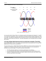
Figure 2: Sine Commutation waveforms ............................................................................................5
Figure 3: DCX-AT300 motion Control Motherboard ...........................................................................6
Figure 4: DCX-MC320 sine commutation servo control module.........................................................6
Figure 5: DCX-BF320 interconnect card ............................................................................................6
Figure 6: Typical system interconnect diagram ..................................................................................7
Figure 7: WinControl – MCCL command user interface .....................................................................9
Figure 8: Example commutation angle / output voltage.....................................................................10
Figure 9: Linear motor diagram.........................................................................................................12
Figure 10: Commutation circuit block diagram ..................................................................................17
Figure 11: Servo Tuning program .....................................................................................................19
Precision MicroControl Corp.
2