1
Installation
KMD-7101/7101C Direct Digital Controller Installation & Operation Guide
Board Installation
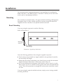
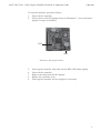
Carefully position the controller board in the provided mounting tracks.
Input Connections
Universal Inputs
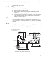
Inputs are connected to the I/O terminal block using connections IN1–IN4.
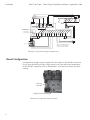
Observe the following guidelines. (Refer to Illustration 2.)
◆
Connect device inputs to the input terminal connections for inputs IN1–IN4.
◆
Connect all grounds to the common GND reference terminal.
◆
If no input pull-ups are required, (i.e. the controller does not souurce the +5
VDC to the device) refer to “Configuration” later in this section.
RS-485 Inputs
Make connections to a network using the A, B and GND terminals on the I/O
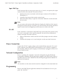
terminal block. If the Controller is at the End-of-Line, refer to “Configuration”
after connections are completed.
Detail
The End-of-Line connection will have only one wire attached to the A and B
terminals.
◆
For reliable operation, use Belden cable model #82760 or equivalent (18 gauge,
twisted, shielded, 50 picofarads or less) for all network terminal block connections.
◆
Connect the nodes of the network in a daisy-chain arrangement. This means:
Connect the A terminal in parallel with all other A terminals.
Connect the B terminal in parallel with all other B terminals.
◆
Connect the shields of the cable together at each controller.
◆
Connect the shields to an earth ground (if available) or chassis ground only at
one end of the segment; tape back the shield ground at the other end.
Connecting Outputs
The Controller provides different combinations of outputs depending on the
model:
7101/01C - Three mechanical relays for staging fan speeds, two Triac relays for
operating heating and cooling valves and three LED outputs.
7102/02C - Three mechanical relays for staging fan speeds, one mechanical relay
for an auxiliary heating element, two Triac relays for operating heating and
cooling valves and three LED outputs.
4