1
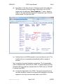
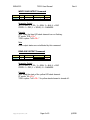
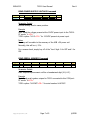
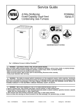
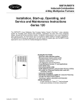
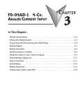
MAN-4312
T4510 User Manual
Rev A
User Manual
T4510
Relay Controller for Lightstack Application
[email protected]
Page 1 of 9
©EE2X
MAN-4312
1.
T4510 User Manual
Rev A
Theory of Operation
The T4510 Relay Controller is intended for connection between a personal
computer (PC) USB port and a 5-element LED-based light stack with
red/yellow/green/blue LED lights and an audible alarm buzzer element.
The T4510 includes a USB drive chip which allows the device to function
as a serial communication (COM) port from the PC’s perspective. When
controlled by application software or a communications port terminal
application (e.g. HyperTerminal) using the instructions described in this
manual, the T4510 allows individual output of flashing, solid, or off states
to each of the five light stack elements.
2.
Installation Procedure
This sections details the driver software installation and connections
required to setup the module for software control. A Windows-based
installation is presumed. Contact [email protected] for if installation is
required for a different operating system (OS).
First, install the Virtual COM Port Driver on the PC to which the T4510 will
be connected as described in following steps.
IMPORTANT:
Virtual COM Port driver software installation
MUST be accomplished BEFORE USB hardware
cable is connected between the host PC and the
T4510.
(a) Go to this URL: http://www.ftdichip.com/Drivers/VCP.htm
[email protected]
Page 2 of 9
©EE2X
MAN-4312
T4510 User Manual
Rev A
(b) Scroll down to the area (shown in following screen shot) under the
VCP Drivers section of the web page. Right-click on the 2.08.02
(setup.exe) link and select “Save Target As…” option. Specify a
folder on the local hard drive to which a temporary copy of this file
maybe stored. It is less than 2MB.
(c)
Double-click on the EXE file saved on your hard drive to run it. The
installer will run to completion automatically within a couple of
minutes.
Next, complete all required hardware connections. The recommended
order is detailed below. Note that the 12VDC, 1A power supply and USB
(standard A-B type) cable are included with the T4510 when a T4510KIT
is ordered from EE2X.
(d) Connect the light stack to the T4510. The signal wires/colors from
the stack should be routed to the wires/colors indicated on the label
adjacent to the 9-pin screw terminal block on the T4510.
[email protected]
Page 3 of 9
©EE2X
MAN-4312
T4510 User Manual
Rev A
(e) Connect the USB cable between the host PC (“A” end) and the T4510
(“B” end).
(f)
Connect the 12VDC power supply to the T4510 (2.1mm jack).
IMPORTANT:
The AC power input for the 12VDC power module
needs to come from the same mains circuit as
that which is powering the host PC.
(g) Connect the 12VDC power supply to the AC power supply.
3.
Command Reference
The T4510 uses an ASCII command set. Each command includes a string
of printable ASCII characters followed by a termination character <CR>.
The commands do not have any restrictions as far as maximum character
delays, etc. The commands will be assembled and interpreted as they are
received. This allows for the creation of either an automated interface
using compiler tools (for example Microsoft Visual C++, Microsoft Visual
Basic, LabVIEW, LabWindows/CVI) which access built in COM port
function of the OS or for the use of a high-level direct command interface
like HyperTerminal.
COM Port Configuration
You may obtain/control the COM port number to which the T4510 device
is assigned using the Windows Device Manager. If the driver software and
device were installed correctly as described in the previous section, the
device will appear under the port list in the device manager as COM3 (for
example). You will need this COM port index to access and control the
device programmatically or with HyperTerminal. In addition to the COM
port index, you will need to be aware of the following settings required to
communicate with the T4510 through the COM port on the host PC.
Baud Rate
Data Bits
Stop Bits
Parity
Handshaking
[email protected]
115200
8
1
None
None
Page 4 of 9
©EE2X
MAN-4312
T4510 User Manual
Rev A
WRITE ALL OUTPUTS Command
Xmitter
PC
T4510
CMD
A
a
RED param
0 – 2
0 – 2
YEL param
0 – 2
0 – 2
GRN param
0 – 2
0 – 2
BLU Param
0 – 2
0 – 2
BUZ param
0 – 2
0 – 2
TERM
<CR>
<CR>
Parameter Details
0 = OFF; 1 = SOLID; 2 = FLASHING for each of the 5 parameters
Example
Goal: Set the green output on solid, yellow flashing, and all others off.
PC sends: “A02100<CR>”
T4510 replies: “a02100<CR>”
READ ALL OUTPUTS Command
Xmitter
PC
T4510
CMD
a
a
RED param
YEL param
GRN param
BLU Param
BUZ param
0 – 2
0 – 2
0 – 2
0 – 2
0 – 2
TERM
<CR>
<CR>
Parameter Details
0 = OFF; 1 = SOLID; 2 = FLASHING for each of 5 return parameters
Example
Goal: Read all output states.
PC sends: “a<CR>”
T4510 replies: “a10021<CR>” for red/buzzer solid on, blue flashing, and
yellow and green turned off.
[email protected]
Page 5 of 9
©EE2X
MAN-4312
T4510 User Manual
Rev A
WRITE ONE OUTPUT Command
Xmitter
PC
T4510
CMD
B
b
ID param
0 – 4
0 – 4
STATE param
0 – 2
0 – 2
TERM
<CR>
<CR>
Parameter Details
ID: 0 = RED; 1 = YEL; 2 = GRN; 3 = BLU; 4 = BUZ
STATE: 0 = OFF; 1 = SOLID; 2 = FLASHING
Example
Goal: Make the blue LED stack element turn on flashing.
PC sends: “B32<CR>”
T4510 replies: “b32<CR>”
Note
Other output states are not affected by this command.
READ ONE OUTPUT Command
Xmitter
PC
T4510
CMD
b
b
ID param
0 – 4
0 – 4
STATE param
0 – 2
TERM
<CR>
<CR>
Parameter Details
ID: 0 = RED; 1 = YEL; 2 = GRN; 3 = BLU; 4 = BUZ
STATE: 0 = OFF; 1 = SOLID; 2 = FLASHING
Example
Goal: Read the state of the yellow LED stack element.
PC sends: “b1<CR>”
T4510 replies: “b10<CR>” for yellow stack element is turned off.
[email protected]
Page 6 of 9
©EE2X
MAN-4312
T4510 User Manual
Rev A
READ POWER SUPPLY VOLTAGE Command
Xmitter
PC
T4510
CMD
c
c
Tens
Ones
Decimal
Tenths
0 - 9
0 - 9
.
0 - 9
TERM
<CR>
<CR>
Parameter Details
Decimal always fixed in same position.
Example
Goal: Read the voltage present at the 12VDC power input to the T4510.
PC sends: “c<CR>”
T4510 replies: “c12.3<CR>” for 12.3VDC present at power input.
Notes
Accuracy will correlate to the accuracy of the USB +5V power rail.
Normally, this will be +/- 5%.
For a coarse check, simply key off of the “tens” digit. 0 for OFF and 1 for
ON.
READ SERIAL NUMBER Command
Xmitter
PC
T4510
CMD
d
d
AlphNum1
AlphNum2
AlphNum3
AlphNum4
AlphNum5
AlphNum6
0-9, A-F
0-9, A-F
0-9, A-F
0-9, A-F
0-9, A-F
0-9, A-F
TERM
<CR>
<CR>
Parameter Details
Each response alphanumeric will be a hexadecimal digit (0-9, A-F).
Example
Goal: Read serial number unique for T4510 connected to this COM port.
PC sends: “d<CR>”
T4510 replies: “d147ACF<CR>” for serial number 0x147ACF.
[email protected]
Page 7 of 9
©EE2X
MAN-4312
T4510 User Manual
Rev A
CONFIGURE EXTRA LINEFEEDS Command
Xmitter
PC
T4510
CMD
E
e
Leading
0 – 1
0 – 1
Trailing
0 - 1
0 - 1
TERM
<CR>
<CR>
Parameter Details
Leading: 0 = No leading linefeed; 1 = Prefix response with linefeed
Trailing: 0 = No trailing linefeed; 1 = Append linefeed to response
Example
Goal: Turn on leading and trailing linefeeds.
PC sends: “E11<CR>”
T4510 replies: “<LF>e11<CR><LF>”
Notes
New linefeed settings are applied immediately to the response of this
command.
This feature might be beneficial for making a HyperTerminal session more
readable.
It is presumed that the linefeeds will typically not be used. By default,
leading and trailing linefeeds are both turned OFF at power up (i.e. when
the USB connection to the device is made).
[email protected]
Page 8 of 9
©EE2X
MAN-4312
4.
T4510 User Manual
Rev A
Additional Notes
Serial Communication Buffer
Serial communication to the T4510 will fill a 10-character buffer. If more
than 10 characters are transmitted to the device by the PC, the first 9
characters will be stored and the last character will be continuously
overwritten by each additional character received. No response will ever
be generated by the T4510 until the <CR> termination character is
received. When the termination character is received, the buffer is parsed
and a response is generated. If the buffer does not contain a valid
formatted command (including <CR>) beginning with the first character
in the buffer upon receipt of the termination character, the response will
always be “?<CR>” After the termination character is received, the buffer
will be emptied and it may be possible to queue up to one additional
command before the response of the first command is completely
transmitted.
Output Delay
To ensure that the relays are not abused by rapid cycling and to avoid
unexpected operational overlap of competing output relays, a minimum
one-second delay will always be enforced when a relay state transitions to
either the SOLID or FLASHING output state. However, transition to the
OFF state will be applied as quickly as possible and transitions back and
forth between the SOLID and FLASHING states will always pass through
the OFF state first.
But it is important to note that commanded output states are always
recognized immediately. That is, if a relay is OFF and then commanded to
the SOLID state and then immediately polled 50 milliseconds later, it will
report the state which it has been commanded (i.e. SOLID) rather than
the state in which it is currently delayed (i.e. OFF).
Power-Up Default Conditions
When 12V is powered to the device and the USB connection is missing,
the red, yellow, green, and blue outputs will all turn on flashing and the
buzzer will remain off.
When the USB connection is made to the device with or without 12V
power supplied, all outputs will be turned off within approximately one
second.
Optional extra linefeed padding characters for T4510 response strings are
always initialized off when USB is connected to the T4510.
[email protected]
Page 9 of 9
©EE2X