1
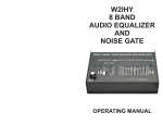
W2IHY
AUDIO EQUALIZER
AND
NOISE GATE
OPERATING MANUAL
W2IHY AUDIO EQUALIZER
AND NOISE GATE
OPERATING MANUAL
MIC OUT & POWER CABLE WIRING
Japan Radio
JST-135
JST-245
Yaesu
FT990/ft992
FT1000MP/M-V
Ft2000 Ft9000
FLEX 5000
Kenwood
TS130/140
TS430/440
TS850/TS870
TS930/940/950
SG2020
K2,K3
+ Mic
8 Pin Mic Connector Pin 8
- Mic
8 Pin Mic Connector Pin 7
PTT
Gnd
8 Pin Mic Connector Pin 6
Shield of Cable
+ Mic
8 Pin Mic Connector Pin 1
- Mic
8 Pin Mic Connector Pin 7
PTT
Gnd
8 Pin Mic Connector Pin 2
Shield of Cable
+ Mic
December, 2004
Yaesu
FT102
FT747/757/767
FT847
FT1000/1000D
PTT
GND
+ Mic
8 Pin Mic Connector Pin 6
Shield of Cable
E-mail: Julius @ W2IHY.COM
Rev 4
Home Page: http:// www.w2ihy.com
c 1995 W2IHY, ALL RIGHTS RESERVED
-2-
PTT
GND
ICOM
735
745/746
756/756 PRO
775
781
7600 7700
ICOM BALANCED
MODULATOR
746
756 / 756 PRO
775
781
910H
7600 7700
8 Pin Mic Connector Pin 3
Shield of Cable
+ Mic
- Mic
8 Pin Mic Connector Pin 7
8 Pin Mic Connector Pin 5
Shield of Cable
+ Mic
8 Pin Mic Connector Pin 6
8 Pin DIN Connector Pin 4
- Mic
PTT
GND
8 Pin Mic Connector Pin 1
8 Pin Mic Connector Pin 1
PTT
Gnd
8 Pin Mic Connector Pin 7
8 Pin Mic Connector Pin 2
- Mic
W2IHY
19 Vanessa Lane
Staatsburg, N.Y. (12580)
(845) 889-4253
8 Pin Mic Connector Pin 8
8 Pin Mic Connector Pin 8
- Mic
KACHINA
8 Pin Mic Connector Pin 5
8 Pin DIN Connector Pin 3
Shield of Cable
8 Pin DIN Connector Pin 2
DIN connectors shown on the side to be soldered
DO NOT SOLDER TO SHIELD OF DIN
-19-
MIC OUT & POWER CABLE WIRING
+ Audio
4 Pin Mic Connector Pin 1
- Audio
DRAKE TR7
Introduction ...........................5
PTT
4 Pin Mic Connector Pin 2
Shield of Cable
GND
4 Pin Mic Connector Pin 3
+ Audio
4 Pin Mic Connector Pin 1
- Audio
4 PIN TEN TEC
EXCEPT ORION
PTT
4 Pin Mic Connector Pin 3
Shield of Cable
GND
4 Pin Mic Connector Pin 2
+ Audio
4 Pin Mic Connector Pin 1
- Audio
TEN TEC
ORION
4 Pin Mic Connector Pin 2
PTT
4 Pin Mic Connector Pin 3
Shield of Cable
GND
4 Pin Mic Connector metal shell
+ Audio
4 Pin Mic Connector Pin 1
- Audio
Kenwood
TS520/TS530
TS820/TS830
4 Pin Mic Connector Pin 4
PTT
GND
4 Pin Mic Connector Pin 2
Shield of Cable
+ Audio
Yaesu
FT101E
FT901DM
Galaxy
4 Pin Mic Connector Pin 3
4 Pin Mic Connector Pin 2
- Audio
PTT
GND
TABLE OF CONTENTS
Front Panel Controls
- Pictorial ............................ 6
- Power On/Off ................... 6
- Power On LED ................. 6
- Equalizer On/Off .............. 6
- Equalizer Bass ................. 7
- Equalizer Treble ............... 7
- Noise Gate On/Off Switch.7
- Noise Gate LED ................ 7
- Noise Gate Level .............. 7
- Noise Gate Delay ..............8
- Mic Gain LED ................... 8
4 Pin Mic Connector Pin 3
Shield of Cable
4 Pin Mic Connector Pin 1
DIN connectors shown on the side to be soldered
DO NOT SOLDER TO SHIELD OF DIN
-18-
Schematic..........................10,11
PC Board and Parts............. 16
Internal Wiring ...................... 17
Mic Out & Pwr. Cable Wiring.18
-3-
INTERNAL WIRING
TABLE OF CONTENTS
Rear Panel Controls
- Pictorial .................... 9
- Mic Select ................. 9
- Mic Input ................... 9
- Mic Input (RCA) ........ 12
- PTT Input (RCA) ....... 12
- Mic Output ................ 12
- Power ........................ 12
J2
J1-9
Bla
ck
13
C uf
.1
MIC IN
Bla
ck
MIC IN
MIC OUT
+ 7 to 14VDC J4
J3
bare wire
Bl
ac
k
S4
PTT
C7
.1 uf
10"- Route between R18 and R17
bare wire
LED1
21"- Route between R18 and R17
J1-11
Shortest
Lead
LED3
R17
100K
J1-7
S2
J1-1
J1-16
J1-14
J1-13
J1-2
Shortest
Lead
R26
R18
25K
25K
J1-12
J1-5
R15
2.2K J1-6
Red - Red - Red
S3
>
>
J1-4
R16
25K
J1-10
J1-15
J1-3
Shortest
Lead
> LED2
15"
Bottom Panel Controls
- Pictorial .................... 13
- Mic In Gain ............... 13
- Mic Output Level ..... 13
J6
POWER
PIN 1
PIN 7
J5
S1
Black
Getting Started Tutorial.. 14,15
- Adjusting Mic In Level
- Adjusting Mic Out Level
- Adjusting Noise Gate Level
- Adjusting Noise Gate Delay
- Adjusting the Equalizer
-4-
15"
Black
Bl
ac
k
Black
RE
Shield not D
Connected
FIGURE 1
-17-
PC BOARD LAYOUT AND PARTS
INTRODUCTION
W2IHY AUDIO EQUALIZER
AND
NOISE GATE
No part installed in parts filled in GREY (C5,R23,R24)
C1-C3,C6, C14 -- 4.7 uf Miniature Radial Electrolytic 50V
C5 -- not used
C8 -- 22 uf Minature Electrolytic 16 V
C9-C12,C15 --100uf Miniature Radial Electrolytic 50V
C7,C13,C16-C17 -- .1 uf monolithic or Disc Ceramic 50V
C18, C19 -- .1 uf Mylar Capacitor
C20, C21 - -.01 uf Mylar Capacitor
C26 - C29 - -.001 uf Mylar Capacitor
C22 -- .033 uf Mylar Capacitor
C4 -- 120 pf Ceramic Disc
C25 -- 560 pf Ceramic Disc
C23-C24 -- 470 uf Miniature Radial Electrolytic 16V
D1-D2 -- 1N914 or 1N4148 Switching Diodes
D3 -- 1N4001
JMPR -- 2 Pin Strip Line Plug (.100") and Shorting Block
J1 -- 16 Pin IDC DIP Flat Ribbon Cable
J2 -- 8 Pin Male Microphone Connector
J3 -- 5 Pin Female DIN Socket
J4-J5 -- RCA Chassis Mounted Phono Jack
J6 -- 5 Female Din Socket (with 2 Pins removed)
LED1 -- Panel Mount 5mm Green LED
LED2 -- Panel Mount 5mm Red LED
LED3 -- Panel Mounted 5mm Orange (or yellow) LED
Q1 -- 2N3417 Switching Transistor
REG1 --7805 +5V Linear Regulator in T220 Case (Use Heat Sink)
RFC1- RFC3 -- 470 uh Miniature (Epoxy Coated) R.F. Choke
R1-R2 -- 10K ohm 10 Pin, 5 Resistor SIP Network
R3 -- 100 ohm 10 Pin, 5 Resistor SIP Network
R4 -- 1K ohm 10 Pin, 5 Resistor SIP Network
R5-R6 -- 10 ohm 1/4 Watt 5 % Resistor
R25 -- 1K ohm 1/4 Watt 5% Resistor
R7, R19 -- 6.8K ohm 1/4 Watt 5% Resistor
R20 -- 10K ohm 1/4 Watt 5% Resistor
R8 -- 5.6K ohm 1/4 Watt 5% Resistor
R9-R10 -- 47K ohm 1/4 Watt 5% Resistor
R11,R21, R26 -- 2.2K ohm 1/4 Watt 5% Resistor
R23, R24 -- not used
R22 -- 3.8M 1/4 Watt 5% Resistor
R12*, R13 -- 100K ohm Horizontal Mounted P.C. Trimmer
R14 -- 0K ohm 1/4 Watt 5 % Resistor
R15 R16, R18 -- 25K ohm Slide Potentiometer
R17-- 100K ohm Slide Potentiometer
S1-S3 -- SPST Miniature Toggle Switch
S4 -- 4 Pole 3 Position (non-shorting) Rotary Switch
U1 -- TL074 or JRC2060D
U2 -- 74HC00
U3 -- 74LS123
U4 -- 74HC4053
T1 -- 600 ohms Primary: 600 ohms Secandary audio transformer
BOLD printed parts mounted in case not on P.C. board
-16-
* Parts mounted on Pin side of P.C. board
Analog and digital technology have for many years been used in the
audio industry to do audio equalization and noise reduction. Many
amateurs have purchased audio equalizers and other equipment with
the hope of improving their transmitted audio signal. The amateurs who
have succeeded have in many cases had to pay premium prices for
audio equipment that not only required modifiing, to properly
interface with their amateur stations, but also had to be hardened to
tolerate R.F.
The W2IHY Audio Equalizer and Noise Gate solves two basic
problems many hams experience. The Audio Equalizer allows the
user to change the transmitted audio frequency response without
changing microphones or microphone cartridges. Transmitted audio,
that has a significant amount of high frequencies present, can be
used to work DX or communicate in band conditions where there is a
significant amount of noise. A balanced frequency response may
be more desirable in strong signal, full noise quieting environments.
Many amateur operators transmit audio in high ambient noise
environments. Typical high noise sources include linear amplifier
fans, dehumidifiers, room air conditioners, road and wind noise during
mobile operation,... The Noise Gate eliminates the aforementioned
noise from being transmitted. On the air tests in high ambient noise
conditions have shown the Noise Gate to be very effective. The
removal of moderate to very high levels of ambient noise, from the
transmitted audio signal, results in audio with increased clarity and
presence.
Extensive testing was done of the Noise Gate and Equalizer. The unit
has been designed to work in high RF environments. We feel so
confident that you will be delighted with the unit we offer a 30 day
money back , no questions asked, guarantee. The W2IHY Audio
Equalizer and Noise Gate represents affordable audio technology
designed for amateur radio use.
-5-
FRONT PANEL CONTROLS
10
7
2
1
8
9
GETTING STARTED TUTORIAL
6
3
4
5
This section describes each of the controls on the front panel. You
can read through this section now. Some of the descriptions
will be more meaningful after you first work through the getting
started tutorial.
(1) Power On/Off Switch (S1)
This switch turns the unit's power on and off.
(2) Power on LED (LED3)
This LED goes on when power is on in the unit.
(3) Equalizer On/Off Switch (S3)
The Noise Gate Delay control sets the decay time of the trailing
edge of the Mic Out Audio, when the noise gate turns off. This
circuitry exponentially reduces the audio output when there is no
audio present in the Mic In. (The delay circuitry helps to make the
transitions of gating and not gating of audio smooth and more
pleasing to the ear.) The duration of the exponential decay
is dependent on the setting of the Noise Gate Delay control. The
delay control set at a minimum value (the slide pot all the way
down) will exponentially decay the audio in about 100 milliseconds.
The delay control set at a maximum value will allow the audio to
decay over several seconds. On the air tests show the mid part
of the Noise Gate Delay range gives very pleasing audio transitions.
(decay time of about .3 to .8 second). You can experiment on your
own to find the best setting for you.
If you have medium-to-high levels of ambient noise present when
you are transmitting, with the Noise Gate Switch in the off
position, when you stop talking your power meter will indicate R.F.
still being transmitted. (set power meter on avg. power to do this
experiment). When the noise gate is turned on and properly
adjusted when you stop talking the power output will drop to the
bottom of the scale (no power output). People who listen to your
signal will be able to hear the difference and they will wonder where
the noise went.
Adjusting The Audio Equalizer
Turn the Equalizer Switch on. Pushing the Treble control up will
increase the amount of high frequencies present in the Mic Out
audio. Pushing the Bass control up will increase the amount of low
frequencies present in the Mic Out audio. On the air experimentation
will be required to find the optimal settings based upon band
conditions.
This switch turns the equalizer on and off. When the equalizer is
off adjusting the equalizer's bass and treble controls has no
effect on the output audio.
-6-
-15-
GETTING STARTED TUTORIAL
Before plugging the power transformer into the wall preset the
following controls as indicated:
Power, Equalizer and Noise Gate switches all off.
Mic Select to select microphone you will be using.
Connect your microphone into the Mic In rear connector. Plug the
power transformer (module) into the wall and into the Power
connector of the unit. Attach the microphone cable between your
transceiver/transmitter and the Mic Out of the unit. If the microphone
being used is an electret mic (ICOM HM12, SM6,...) and requires
D.C. on the mic line plug the shorting jumper supplied onto the MIC
Jumper pins at the bottom of the case otherwise leave it off. Turn
the Power switch on. The orange Power on LED should go on.
Adjusting the Mic Levels
While talking into the microphone, using a screwdriver, turn the
Mic In Level Control (located at the bottom of the unit) clockwise
until the Mic LED just goes on. The LED should go on 1 or 2
times in a sentence.
While talking into the microphone, using a screwdriver, turn the
Mic Out Level control clockwise until the audio level, as shown by
your transceiver's/ transmitters metering is at the proper level. If
you are using push to talk on your transceiver you will have to
push the PTT switch on your microphone while making this
adjustment.
Noise Gate Adjustments
Turn the Noise Gate Switch on. (Please note that when the
Noise Gate Switch is off the Noise Gate LED should always go
on indicating audio is being sent / gated to the Mic Out. When the
Noise Gate Switch is turned on the Noise Gate LED may be on
or off depending on the position of the Noise Gate Level control
and the Mic In audio level.) Adjust the Noise Gate Level control until
the Noise Gate LED just goes off. This adjustment should be made
with the level of ambient noise that will be present when you will
be talking into the microphone. (If audio is coming from your
transceiver's/ receiver's speaker you should turn off the audio.)
When you now talk into your microphone the Noise Gate LED
should go on indicating audio is being sent to the Mic Out. When
you stop talking the Mic Out LED should turn off indicating
that audio is not being sent and background noise is not being
sent / gated to the Mic Out.
-14-
FRONT PANEL CONTROLS
(4) Equalizer Bass (R15)
This slide potentiometer works only when the equalizer is on.
Pushing the control up increases the amount of bass boost.
Pushing this controldown decreases the amount of bass boost.
(5) Equalizer Treble (R16)
This slide potentiometer works only when the equalizer is on.
Pushing this control up increases the amount of treble boost
Pushing this control down decreases the amount of treble
boost.
(6) Noise Gate On / Off Switch (S2)
This switch turns the noise gate on and off. When the noise
gate is off the changing the gate delay or level controls has
no effect on the audio. When the noise gate is off audio is
always being gated through the noise gate / equalized to the
output.
(7) Noise Gate LED (LED1)
This LED is used to help properly adjust the noise gate level
control and to indicate when audio is being sent (gated) to the
output. The LED being on (green) indicates that audio is being
gated through the unit to the output. The LED being off indicates
that audio is not being gated through to the output. When the
noise gate switch is in the off position (6) the noise gate LED
is on.
(8) Noise Gate Level (R18)
This slide pot. works only when the noise gate is on. This
control sets the level at which background noise will be not
gated to the audio output. Pushing this control up will make the unit
less sensitive to higher background (ambient) noise. Pushing
this control down will make the unit more sensitive to background
noise.
-7-
FRONT PANEL CONTROLS
BOTTOM PANEL CONTROLS
(9) Noise Gate Delay (R17)
This control adjusts the length of time audio will be gated to the
output after the noise gate has automatically turned off (Noise gate
LED off). Pushing the delay slide pot. up increases the delay
(decay) time. Pushing the pot. down decreases the delay time.
(10) Mic Gain LED (LED2)
This LED is used to help adjust the MIC In Gain pot. When the
LED goes on this indicates that the Mic gain is set near the
maximum recommended setting.
19
17
18
(17) Mic Jumper
Plugging shorting block in puts +5V on the mic In line of the
microphone's cartridge (12 & 13). Required for mic's like HM12,
Hm36, SM6 and Heil HM-i and electret microphones.
(18) Mic In Gain (R12)
Changes the microphone amplifier's gain. Gain is increased,
while speaking into microphone until Mic LED (10) just
barely goes on (LED should turn on 1 or 2 times in a sentence.)
(Clockwise rotation increases gain.) Microphone cartridges
with very low output (Like a Heil HC4 or Heil HC5) may
require the Mic In Gain Control to be adjusted to maximum
gain.
(19) Mic Output Level (R13)
Changes the unit's audio output. (Clockwise rotation increases
output.) This input is also low impedance (600 ohms).
-8-
-13-
REAR PANEL CONTROLS
REAR PANEL CONTROLS
(13) Mic Input (J5)
RCA female connector for auxiliary microphone input. This
connector works independently of the mic select switch and
may be used for another audio source or microphone. This
input is also low impedance. Do not use if mic is connected
to J2
(14) PTT INPUT (J4)
RCA female connector for auxiliary push to talk control. A foot
switch or other control may be connected to this connector.
Grounding the center jack of the connector grounds the push
to talk line on the Mic Out.
(15) Mic Output (J3)
5 Pin female DIN connector that has noise gate / equalizer audio
plus push to talk outputted. The audio output is transformer
driven and designed to connect to a low impedance (600 ohms).
16
14
11
13
15
12
(11) Mic Select (S4)
Three position switch that selects the ICOM,KENWOOD or
YAESU microphone plugged into the Mic Input.
+ Mic
MIC OUT
5 Pin Male DIN
- Mic
PTT
Din connectors shown
on side to be soldered
Gnd
(16) Power
5 Pin Din connector. 7 - 14 VDC input at 100 ma.
GND
Power
5 Pin Male DIN
Din connectors shown
on side to be soldered
-12-
+7 to 14V
(12) Mic Input (J2)
8 Pin microphone male connector. Low impedance microphone
(600 ohms) plugs into here.
J2
Pin Icom Ken Yaesu
1 +Mic +Mic
2 +5V PTT +5V
5 PTT +5V PTTGnd
PTT
6 PTTGnd
7 Gnd - Mic Gnd
Gnd +Mic
8
-9-