1
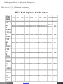
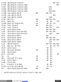
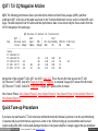
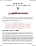
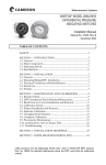
NW2M Presents:
The Yaesu FT-101 HF Transceiver Home Page
Purpose
The purpose of this page is to capture and document the Yaesu FT-101 series radios during the 1970's. It has taken
me 12 years to collect a transceiver and every accessory to make a "complete station". I encourage your feedback,
corrections, and additions. I am not an Electrical Engineer, so I cannot help with specific repair or substitution
problems. I simply don't have access to this type of material or equipment. My objective is to document the Yaesu
FT-101 era and to provide a detailed understanding so that the value of this equipment can be realized.
Thanks, Al-NW2M
FT-101 Web Page
Advertised
open in browser PRO version
Are you a developer? Try out the HTML to PDF API
pdfcrowd.com
FT-101 History
FT-101 Model Numbers
Physical Construction
Advertised
Features
General
Specifications
A "Complete" Station
Station Accessories
Tune-up
Procedures
Known Modifications
6JS6C Tubes
Basic Alignment Points
QST / 73 / CQ
AM Operation
Weights and Shipping
Repair Facilities
Original Prices
Mobile Operations
Fox-Tango
Newsletters
Comments/Corrections
Credits
About the Author - NW2M
A Brief History of the FT-101 Transceiver
The FT-101 series of transceivers first appeared internationally in 1970 and then domestically inside the United
States in January 1971. It gained overnight approval of amateur radio operators for its quality of signal, flexibility and
for professional attention to workmanship and design. The modular design of 10 solid state circuit boards on a
common chassis with a tube amplifier caught the eye of discriminating hams worldwide.
It was a strong performer. Although far from perfect, the first FT-101's suffered from intermod when strong signals
were present during receive and generated spurs on transmit. Hams began to investigate these problems and offer
improvements to existing circuit design. The factory responded with a major modification which significantly
improved the receiver of the early FT-101's. The serial number revealed which transceiver was "early" and "late". So
that the "early" FT-101 hams would not feel obsolete, Yaesu offered the entire modification which made an "early"
into a "late" and sold it as a kit along with a 25 page instruction guide. Problems began as many hams lacked the
proper test equipment and the know-how needed to make such an upgrade. After months of fighting with customers,
Yaesu withdrew the kit (MIR-1 Modification Kit) and would only install it at their factory. Adding to the confusion was
the fact that there were five (5) different sub-models within the "early" FT-101 series, the last being the FT-101 "late"
model. The situation arose where identical FT-101 radios sat side by side with the only indication of the internal
layout was by the serial number.
open in browser PRO version
Are you a developer? Try out the HTML to PDF API
pdfcrowd.com
Additional improvements were made and with the addition of the 160 meter band, the FT-101B was released. Yet
more improvements and the addition of a real "RF" speech processor led to the release of the FT-101E model. The
"E" model was fully refined with all of the previous problems having been worked out. This was the most popular and
the most produced model by Yaesu in the FT-101 series. Three models of the "E" were released. The "E" model
with all options, an "EE" (economy) model lacking the speech processor, and the "EX" (extreme economy) model
lacking speech processor, 160M crystal, DC options, and microphone. Last in the series was the "F" model which
contained all of the modifications, improvements and options throughout the series. Only a few of the "F" models
were made which also included an "FE" (economy) and "FX" (extreme economy) model. With fierce competition in
the HF market, WARC bands on the horizon, IF shift, AF Notch/Peak, and digital readouts, the FT-101 series moved
quickly to the analog "Z" model and then to the digital "ZD" models. The original FT-101 series lasted for 6 years,
beginning in early 1971 and lasting through 1977. It was an exciting time for the FT-101 radios and their owners.
There were no "A", "C", or "D" models produced.
The FT-101 first appeared in the January 1971 issue of QST (page 147) sponsored by Spectronics. It would
become a familiar full-page advertisement that would be used several times by Spectronics Inc as part of their global
ad campaign. It set into motion a new wave of radios and ushered in an exciting time for amateurs worldwide! Each
was hand-made by skilled workers with the utmost of pride. Each was unique.
A publication called the Fox-Tango Newsletter captured the "diary" of the FT-101s for all time. Ten publications per
year offered thousands of FT-101 owners the opportunity to share problems, solutions, and performance data. The
Fox-Tango Newsletters lasted for 14 years. It is the largest collection of user data and factory support information for
any radio at any time. It has been preserved and full copies are still available today. Truly a testament to the era and
popularity of these radios, even today. Here is a link to the Fox-Tango Newsletter page.
!Safety!
Before we go any further, it is paramount that you understand that high voltages exist within these radios, cables, and
accessories. Safety is first and foremost! The FT-101 radios and accessories have voltages which include: 100V,
open in browser PRO version
Are you a developer? Try out the HTML to PDF API
pdfcrowd.com
117V, 240V, +150V, +300V, and +600V. These voltages exit the radio and appear on interface cables. There are
no warnings! Within the high power FL2100 amplifier, there is a +2,600 Volt power supply! Within the YO-100
oscilloscope is a +1,300 Volt power supply and a cathode ray tube (CRT). Special tools are required when working
on these radios, accessories, and interface cables. Professional repair and service are highly recommended. The
following information is presented solely for informational purposes and historical reference.
What's in the Name ?
There are many models which proudly display the FT-101 logo. Please be sure that you know which model you have,
know its operating capabilities, and limitations. Normally, the longer the model number is, the less capabilities it has
for that model. The last 5 digits represent the serial number. Any serial number prefix is for factory control and
routing. Buyers and sellers of the original models needed to know the serial number to finalize any deal. Here is the
complete list:
FT-101 - "Early" model
1971, first offering in United States.
Serial numbers below 25,000.
Known for strong receiver overload, TX spurs, and audio problems.
80-10 meter transceiver.
FT-101 - "Late" Model
Serial numbers above 25,000.
Major modifications to receiver, Regulator, IF and audio boards.
80-10 meter transceiver.
There were five FT-101 sub-models known: (based upon MK-160 160 Meter kit information)
Mark 0: Serial numbers 06000 and below. First "Early" models during 1970.
Mark 0A: Serial numbers 06001 to 07991. Transitional.
Mark I: Serial numbers 08001 to 23999. Most common "Early" model.
open in browser PRO version
Are you a developer? Try out the HTML to PDF API
pdfcrowd.com
Mark II: Serial numbers 24000 to 24999. Transitional models with 160M tank circuit.
Mark IIA: Serial numbers 25000 and up. First "Late" Models.
Beware: Early and Late model circuit boards may not be fully interchangeable!
FT-101B - "Early" Model
Serial numbers below 6,000.
Improved IF (PB1183B) and Audio (PB1315), and Blanker (PB1292) boards.
160-10 meter transceiver.
FT-101B - "Late" Model
Serial numbers 6,001 and up.
Improved Regulator (PB1314A), IF (PB1180B), and Audio (PB1315A) boards.
160-10 meter transceiver.
FT-101BS
Special FT-101B model for Japan Market.
Single 6JS6C tube, 50 watt output.
FT-101E
160-10 meter transceiver.
RF Speech Processor.
Three sub-models:
"Early" - S/N 15,000 and lower. (PB1494) Processor
"Mid" - S/N 15,001-20,500. (PB1534) Processor
"Late" - S/N 20,501 and up. (PB1534A) Processor, (PB1547A) Regulator, (PB1183C) IF, (PB1315B)
Audio, (PB1582) Blanker.
FT-101EE
Economy FT-101E model.
open in browser PRO version
Are you a developer? Try out the HTML to PDF API
pdfcrowd.com
All FT-101E specifications except,
No Speech processor (available as an option).
FT-101EX
Extreme Economy FT-101E model.
All FT-101E specifications except,
No Speech Processor (available as an option).
No DC Converter for Mobile use (available as an option).
No Microphone, DC cord, or 160M crystal, 10A crystal only.
FT-101ES
Special FT-101E model for Japan Market.
Single 6JS6C tube, 50 watt output.
FT-101F
Latest in the FT-101 series. All updates applied.
160-10 meter transceiver. 11 meters as AUX position.
Improved (PB1582) Noise Blanker.
Speech Processor and DC Converter.
FT-101FE
Economy FT-101F model.
All FT-101F specifications except,
No Speech Processor (available as an option).
FT-101FX
Extreme Economy FT-101F Model.
All FT-101F specifications except,
No Speech Processor (available as an option).
No DC Converter for Mobile use (available as an option).
open in browser PRO version
Are you a developer? Try out the HTML to PDF API
pdfcrowd.com
No Microphone, DC cord, or 160M crystal, 10A crystal only.
There were no "A", "C", or "D" models ever produced.
FT-101 Board Complement by Model Number
FT-101
Version
VFO
REG
HF/IF
LO/IF
AUDIO
RF
MOD
RECT
BLANKER PROCESS
FT-101
Part of
(Early)
PB1056 PB1079A PB1084C PB1080A PB1081C PB1077B PB1078A PB1076A
PB1080A
S/N
25,000&Down
None
FT-101 (Late)
S/N
PB1056 PB1185
25,001&Up
PB1180
PB1189 PB1181A PB1184 PB1076B
PB1182
None
FT-101B
(Early)
PB1056 PB1185
S/N
6,000&Down
PB1180 PB1183B PB1315 PB1181B PB1184A PB1076B
PB1292
None
PB1056 PB1314A PB1180B PB1183B PB1315A PB1181B PB1184A PB1076B
PB1292
None
FT101E/EE/EX
PB1056 PB1314A PB1180B PB1183B PB1315A PB1181B PB1184A PB1076B
(Early)
S/N
15,000&Down
PB1292
PB1494
FT101E/EE/EX
PB1056 PB1314A PB1180B PB1183B PB1315A PB1181B PB1184A PB1076B
(Mid)
S/N 15,00020,000
PB1292
PB1534
FT-101B
(Late)
S/N
6,000&Up
open in browser PRO version
PB1183
Are you a developer? Try out the HTML to PDF API
pdfcrowd.com
FT101E/EE/EX
PB1056 PB1314A PB1180B PB1183C PB1315A PB1181B PB1184A PB1076B
(Late)
S/N
20,001&Up
FT101F/FE/FX
(All)
S/N All
Numbers
PB1582
PB1056 PB1547 PB1180B PB1183 PB1315B PB1181B PB1184A PB1076B PB1582B
PB1534A
PB1534A
Why so many sub-models?
FLASHBACK - In 1971, there were 250,000 licenses hams, First Class stamps were 8 cents; Minimum Wage was
1.60 per hour; 8-Track tapes were at their sales peak; Bill Gates was a junior in high school; the original IBM PC was
still 10 years away; Linus Torvalds (Creator of Linux) was 2 years old; a new Chevy Corvette cost $5,500 dollars;
gas prices were 36 cents per gallon; and Atari was 10 months away from releasing "Pong". $500-$550 was a lot of
money for a new ham radio. Numerically, the FT-101 was 1/10th the price of a 1971 Corvette! The Consumer Price
Index (CPI) was 40, today it is 340. Today's equivalent value of a $550 radio is $4,700. Additionally, Novices only
had CW privileges on certain bands- so a microphone, the Speach Processor, 160M crystal and the 10B/C/D
crystals, etc were simply excess cost drivers on an expensive radio. As the Novice upgraded, these could be
purchased to match the operating capabilities permitted by their license class. In 1972, the FCC allowed Novices to
operate a transmitter controlled by a VFO. Ironically, a Novice could not operate a FT-101 with the VFO. Fixed
crystals were needed! How times have changed!
Construction
The FT-101 is a hybrid radio that employs a solid state transmitter, receiver, and a two-tube power amplifier. The
solid state features of the radio offer high-performance, low-noise, and low-current characteristics, while the tube
power amplifier provides a nearly "bullet-proof" transmitter and tuner stage.
The tube amplifier consists of a 12BY7A pre-driver stage that feeds a pair of 6JS6C tubes providing a nominal
open in browser PRO version
Are you a developer? Try out the HTML to PDF API
pdfcrowd.com
output power of 130 watts PEP SSB, 90 watts CW, 30 watts AM. The 6JS6C tubes are matched to 50 Ohms
through a conventional pi-output network. The pi-network transforms the 5500 ohm output impedance of the tubes to
a 50 Ohm feed system, provides harmonic attenuation, and can actually match to a variety of output impedances
from 25 to 100 Ohms with ease.
The transceivers were made with plug-in boards which could be sent to the factory for replacement or repair. This
modular design was unprecedented in the amateur community, which explains why so many FT-101's are still in use
today. In fact, board extenders could be purchased to extend any board above the main chassis for measurement,
alignment, and repair. For any plug-in board, all voltages, grounds, and signal traces were routed through a single
edge connector (facing down into the main chassis). This removed the need for wires and cables to these circuit
boards. This yielded a clean and trim internal upper chassis. The bulk of the wiring harness is below the deck of the
main chassis where all main circuit board edge connectors are fed. Yes, there are many wires!
FT-101 Block Diagram 54k
FT-101 Top Chassis Photo 106k
FT-101 Bottom Chassis Photo 91k
The most complicated device in this radio is the Band Selector Switch. This is a 12-position rotary switch that runs
from the front of the radio to the back. It has 13 sections (wafers A thru M) which route everything from DC voltages,
oscillator sections, crystals, tuning circuits, and RF Power in the high-voltage tank and output circuits. One band
selector switch position is used for: 160M, 80M, 40M, 20M, 15M, 10A, 10B, 10C, 10D, 11M or AUX, and WWV
receive-only. Each position allows the main VFO to cover 500kHz on any band.
The entire transceiver was made of metal. Covers, chassis, shields, shafts, etc., are all metal. Even the plastic RF/Smeter trim and knobs have brass metal inserts. At 35 pounds, there is a lot of metal in this radio! The 10 major circuit
boards are mounted with threaded hardware to the main chassis. Very rugged indeed. A clear plastic sheet covers
the entire painted surface of the faceplate. A well-cared-for FT-101 will still have this clear plastic front. Years later,
vendors offered plastic covers to further protect your FT-101 radio and accessories.
open in browser PRO version
Are you a developer? Try out the HTML to PDF API
pdfcrowd.com
Because critical circuit designs were kept to a manageable size, hams had no problem in offering circuit changes,
isolating and repairing problems. This knowledge base was so active that in January 1972, Milton Lowens
WA2AOQ, founded the International Fox Tango Club and the Fox Tango Newsletter. The Fox Tango Newsletters
were published for 14 years covering the early FT-101's thru the latest Yaesu Transceivers in 1985. By then, surface
mount technology and circuit complexity outpaced many ham's ability to maintain this level of equipment. In doing so,
new chapters in circuit densities, solid state transmitters, and LSI chips were born, which closed the door (and the
covers) to many radios forever.
FT-101 Advertised Features
Built-in AC and DC power supplies.
True RF Speech Processor.
Solid state VFO, 1kHz resolution.
Modulation modes - USB, LSB, CW, AM.
Built-in, adjustable, VOX.
Adjustable CW Side tone.
Selectable 25kHz and 100kHz calibrator/marker.
RIT control +/- 5kHz range.
WWV reception for time and fine frequency calibration.
Built-in speaker.
Eight pole SSB filter. AM or CW filter optional.
Complete line of station accessories providing 160M thru 2M coverage.
General FT-101 Specifications
Frequency Range:
Modes:
open in browser PRO version
3.5-30 MHz*
(80/40/20/15/10 meters)
27.0-27.5 MHz (11/AUX)
10.0-10.5 MHz (WWV receive only)
* 160 meters included with B/E/F Series
USB, LSB, CW, AM
Are you a developer? Try out the HTML to PDF API
pdfcrowd.com
Power Input:
SSB 260 watts PEP DC Input (130
CW 180 watts PEP DC Input ( 90
AM 80 watts PEP DC Input
( 40
TX Freq Response: 300 Hz - 2700 Hz
RX Freq Response: 300 Hz - 2400 Hz Standard Yaesu
500 Hz
Optional Yaesu
Optional Filters: 300 Hz - 1800 Hz SSB Narrow(Fox
250 Hz
CW Narrow (Fox
Audio Output:
3 watts
AC Power:
Rx 35 watts, Tx 300 watts
DC Power:
Rx 0.5 amps, Tx 20.0 amps
Weight:
35 lbs
Size:
6"h x 13-1/2"w x 11-1/2"d
watts output)
watts output)
watts output)
SSB Filter
CW Filter
Tango Filter)
Tango Filter)
A "Complete" Station
Arguments arise when hams talk about a "complete" FT-101 station. Let's set the record straight. Based upon the
Yaesu Service Manual "Accessories", a complete FT-101 station will have the following:
FT-101 Transceiver or FL-101/FR-101 Twins
FV-101 Remote VFO
FL-2100 Linear Amplifier
SP-101PB Phone Patch with Speaker or SP-101 Speaker-only
YO-100 or YO-101 Monitor Scope
YC-601 or YC-601B Digital Display Unit
FTV-250 2 Meter Transverter
FTV-650 6 Meter Transverter
YP-150 Dummy Load / Watt Meter
YD-844 Dynamic Desk Microphone
QTR-24 World Clock
This rounds out the field, and is supported in the Yaesu Manuals and advertising in QST. There may be other items
open in browser PRO version
Are you a developer? Try out the HTML to PDF API
pdfcrowd.com
made by Yaesu during this period, but no mention is made in any of the FT-101 service manuals or documentation.
Yaesu Service Manual pages 1-31 thru 1-39 cover the above items as Accessories. Options included: CW Filter,
Fan, Mobile Mounting Bracket, etc.
Station Accessories
Yaesu made an entire suite of accessories to complement any FT-101 operator's station. Each accessory has been
thoroughly crafted and integrated to extend any operating capability. Adding station accessories allows complete
band coverage from 160 meters on HF through 2 meters (USB, LSB,CW, AM). Here is a list of each accessory,
description, and specifications.
FL-2100B/F/Z Linear Amplifier
| FL-2100 Hook-up diagram | FL-2100 Schematic A | FL-2100 Schematic B | FL-2100 Transformer Wiring |
The FL-2100B/F/Z is a conservatively rated matching amplifier for the FT-101 series. The amplifier features two
rugged 572B carbon plate tubes in a Class B grounded-grid circuit with individually tuned input coils for each band.
The FL-2100B/F/Z operates with dual cooling fans and a solid state power supply. Dual interlocks offer safety and
shock protection. An automatic changeover circuit biases the tube to cut-off on receive to maximize tube life and
minimize heat. A bifilar wound, ferrite chokes ensure minimum RF transfer to the power source. Conservatively rated
at 1200 watts PEP input power on 80 through 10 meters. Dual illuminated front panel meters provide continuous
monitoring of plate current, voltage, relative output, and SWR. A "standby" switch allows the amplifier to be
bypassed with primary power enabled and tubes fully heated for operation. Connections to the FT-101 transceiver
include TX/RX relay control and ALC control voltages. Such control lines are typical for all FT-101 accessories.
There were three FL2100 models produced: FL2100B, FL2100F, and FL2100Z. The FL2100 B and F models
cover 80-10 meters, the Z model includes 160 and WARC bands.
FL-2000B/F/Z Specifications:
Frequency Range*: 3.5-4 MHz, 7.0-7.5 MHz, 14.0-14.5 MHz, 21.0-21.5 MHz, 28.0-29.9 MHz.
* The FL2100Z covers 160 Meter Band 1.8-2.0 MHz, 18 MHz, and 24 MHz WARC bands.
Plate Input Power: 1200 watts PEP on SSB, 800 watts on CW, and 600 watts AM.
open in browser PRO version
Are you a developer? Try out the HTML to PDF API
pdfcrowd.com
Drive Requirements: 30 to 100 watts.
Input Impedance: 50 Ohms, unbalanced.
Output Impedance: 50 Ohms, unbalanced, SWR less than 2:1.
Distortion Products: -30dB at 1200 watts input.
Noise Level: 40 dB below single tone carrier.
Circuitry: A pair of 572B in grounded grid, class B.
Warm-up: Less than 10-seconds.
Power Requirements: 100/110/117 VAC at 18 amps. 200/220/234 VAC at 9 amps.
Size: 6"h x 13-1/2"w x 11-1/2"d
Weight: 41 lbs
FV-101B External VFO
Adding the FV-101B External VFO to your station opens up a new world of operating flexibility. DX'ers will really
appreciate this combination. The FV-101B features the same factory sealed, solid state, 1kHz resolution, VFO that
is found inside the FT-101 transceiver. This flexibility allows for "split" operation for separate transmit and receive
frequencies in any band. Regardless of VFO mode, the exact transmit and receive frequency are available for the
Digital Display (YC-601 or DD-1) unit. Please note that any frequency split occurs within the same band. The
Remote VFO does not offer cross-band operation. Four VFO modes are supported:
1.
2.
3.
4.
Transmit and Receive from Main VFO (normal mode)
Transmit from Main VFO, Receive from Remote VFO
Transmit from Remote VFO, Receive from Main VFO
Transmit and Receive from Remote VFO
FV-101B Specifications:
Frequency Range: 8.7 to 9.2 MHz (500kHz tuning range)
Frequency Stability: Within 100 Hz in any 30 minute period after warm-up
Power Source: Remote VFO Connection on the rear of the FT-101 transceiver
Size: 6"h x 8-1/4"w x 11-1/4"d
Weight: 7-1/2 lbs
open in browser PRO version
Are you a developer? Try out the HTML to PDF API
pdfcrowd.com
YO-100 / YO-101 Monitor Scope
| YO-100 Schematic A | YO-100 Schematic B |
Adding the YO-100 Monitor Scope allows you to monitor and adjust your transmitter for the cleanest signal possible.
Compatible with virtually any transmitter or transceiver, the Station Monitor features a wide range of inputs for all
mode monitoring, even RTTY. A built-in 1500 Hz and 1900 Hz tone generators adds to the versatility of this
accessory. The two-tone generator generates the proper audio signals to perform "trapezoidal" pattern testing for
transmitter linearity. A full complement of front controls allows operator control of all key adjustments. The YO-101 is
a solid state version of the YO-100.
YO-100 / YO-101 Monitor Scope Specifications:
Vertical Trace Performance
Sensitivity: 200 mV P-P/cm
Frequency Response: Direct 10Hz to 60MHz
Horizontal Trace Performance
Sensitivity: 300 mV/cm
Frequency Response: 10Hz to 16kHz
Sweep Frequency: 10 Hz to 10 kHz
Two-Tone Generator Performance
Frequency: 1500 Hz and 1900 Hz, Independently selectable
Output Level: 50 mV
Power Requirements: 100/110/117/200/220/234 VAC 50/60 Hz
Size: 6"h x 8-1/4"w x 11"d
Weight: 13 lbs
YD-844 Dynamic Base Microphone
open in browser PRO version
Are you a developer? Try out the HTML to PDF API
pdfcrowd.com
| YD-844 Hookup |
The YD-844 is an attractive and functional necessity for serious base-station operation. The unit is made of heavy
cast metal which rests solidly at your operating position. The microphone element is dynamic (voice-coil) and is
balanced (output levels and impedances) for use with the FT-101 transceiver. Two PPT (push to talk) buttons are
available on the YD-844 microphone. One button is a momentary-switch which must be depressed to activate the
PTT relay, the second button has a lock feature which allows hands-free operating (while still transmitting via PTT).
The microphone element is always connected to the FT-101 so that VOX operations are available without
depressing any microphone PTT buttons. The FT-101 transceiver has three transmit options: 1-MOX (Manually
Operated transmitter), 2-PPT (Push To Talk), and 3-VOX (Voice Operated Transmitter). These three options are
available on the front panel of the FT-101 Transceiver via toggle switch. The YD-844 is available in both high and low
impedances. The microphone cord is a 3' coiled, 4 conductor (one shielded) cable terminating into a 4-pin female
connector.
YD-844 Specifications:
Impedance: 500 Ohms at 1kHz, or 50k Ohms at 1kHz
Output: 50mV nominal
Frequency Response: 50Hz-10kHz nominal
Directivity: Uni-directional
Size: 9"h x 3"w x 6"d
Weight: 1-3/4 lbs
QTR-24 World Clock
QTR-24
The QTR-24 World Clock is a 12 and 24 hour format clock. The standard clock movement (hours, minutes, seconds)
is represented in a classical 12-hour format. An outer ring depicts time in a 24-hour format. The first 12 hours are
shown in white to depict daylight and the other 12 hours in black depict night. The outer-most perimeter of the clock
face has the names of 70 major cities throughout the world in each of the 24 global time zones. As the 24-hour ring
passes a group of cities, you can easily see their UTC and a day/night indication. The QTR-24 has three
adjustments on the rear. One for time (basic movement adjustments), one for the 24-hour ring, and one for fine-time
open in browser PRO version
Are you a developer? Try out the HTML to PDF API
pdfcrowd.com
adjustment. The QTR-24 can be adjusted to be accurate within ±10 seconds per month.
The current name and format for world time is called Universal Time Coordinate (UTC). It has also been known over
the past years as Greenwich Mean Time (GMT), and the military term ZULU (Z). World time is represented in a 24hour format based upon the global starting point in Greenwich, England (UK). The UTC time standard does not
adjust for Daylight Savings Time.
Accurate time reception can be found by tuning to WWV/WWVH (10.000MHz) or CHU (7.335) on the FT-101
transceiver. Alternate HF/shortwave frequencies for WWV/WWVH are 2.500, 5.000, 10.000, 15.000, and 20.000
MHz. All time formats are AM broadcasts. The WWV (male voice) originates from Ft. Collins, Colorado (USA). The
WWVH (female voice) originates from Kauai, Hawaii (USA). The ultra-high accuracy of the WWV 10.000MHz signal
is also used to calibrate the FT-101 internal marker located on the Regulator Board (TC 1). Radio station CHU in
Ottawa, Ontario (Canada) can be found on 3.330, 7.335, and 14.670 MHz.
Setting up your QTR-24 Clock. Using the internet, go to time.is, set your QTR-24 clock to your local time (rear
knob adjustment), and rotate the white 24-hour bezel ring (rear knob adjustment) so that the top agrees with the 24hour value for London/Greenwich Time. See the image of the QTR-24 which depicts a local time of 08:38:45am
local, and a GMT time between 13 and 14 hours. Additionally, my time zone is the same as New York. The 24-hour
bezel depicts between 8am and 9am (in white) UTC. The QRT-24 is properly set.
Allow the QTR-24 to run for a few days. The speed of the clock may be adjusted via flat blade screwdriver.
Clockwise one tick mark to advance the device 5-seconds per day, Counter-Clockwise to retard the clock 5seconds per day.
QTR-24 Specifications:
Time Format: 12 and 24 hour formats
Accuracy: Continuously adjustable, ±10 sec/month, nominal
Power: 1.5V, single C-cell battery, replace yearly
Internal Movement: Oscillating spring wheel
External Movement: Hours, minutes, seconds, 24 hour ring day/night indication
open in browser PRO version
Are you a developer? Try out the HTML to PDF API
pdfcrowd.com
Construction: Black plastic frame, glass face with chrome trim
Mounting: Wall mount or desktop with tilt-bail
Size: 6" diameter, 2-1/2" deep
Weight: 1 lb
YP-150 Dummy Load / Watt Meter
| YP-150 Schematic |
The YP-150 is a 50 Ohm dummy load with a built-in RF watt meter. This unit provides a 50 Ohm resistive load to any
transmitter operating from 1.8Mhz thru 200MHz. A single PL-259 plug on the rear panel provides the unbalanced
input to this unit. The YP-150 is powered by a 117V AC source to run an internal cooling fan to remove heat from the
50 Ohm non-inductive load. Although YP-150 is powered, the front panel meter is not illuminated. A four-position
switch allows accurate RF power measurements from 0-6 watts, 0-30 watts, and 0-150 watts. The fourth position is
the OFF position which removes power to the fan and disconnects the power measuring unit. The YP-601 can be
operated without AC power, but this practice is not recommended, as excessive heat can damage the resistive
load. There is no provision for an RF "bypass", therefore this unit is best suited for bench testing and alignment
procedures.
YP-150 Specifications:
Frequency Range: 1.8MHz to 200MHz
Power Scales: 0-6 watts, 0-30 watts, 0-150 watts
SWR: Less than 1.2:1 at 145MHz
Accuracy: Better than 10% of maximum scale
Meter: Logarithmic scale, non-illuminated
Connection: Single PL-259, unbalanced
Power: 117V AC for internal cooling fan
Size: 6"h x 4-1/2"w x 11"d
Weight: 7.0 lbs
SP-101 External Speaker and SP-101PB External Speaker and Phone Patch
open in browser PRO version
Are you a developer? Try out the HTML to PDF API
pdfcrowd.com
| SP-101PB Hook-up diagram | SP-101SP Schematic |
The Yaesu SP-101 and SP-101PB provide audio fidelity that is unmatched by the internal speakers found in most
conventional HF transceivers. Although all of the FT-101 series of transceivers have internal speakers (some early
radios did NOT have speakers!), the SP-101 External Speaker provides an audio fidelity and presence which
cannot be matched with a small 3" internal speaker. The SP-101 internal speaker uses the entire speaker enclosure
to produce pleasing tonal qualities needed for the reception of rich AM, sharp SSB, and narrow CW. There are no
audio filters in the SP-101 to change the audio properties originating from the FT-101. Connection to the SP-101 is
with shielded RCA connectors. It is strongly suggested that small diameter coax or highly shielded audio be used to
ensure shielding from the transceiver to the remote speaker. The SP (speaker output) jack on the FT-101 has some
RF suppression, and is one of the first places to look for feedback and hum especially at kW levels during transmit.
The SP-101PB contains all of the excellent audio properties and characteristics as the SP-101 speaker-only model
with the addition of a hybrid telephone-patch circuit. This circuit allows the FT-101 transceiver to be interconnected
to your telephone circuit to allow telephone calls to be placed with over-the-air stations. The SP-101PB has two level
controls to ensure proper audio levels are presented to the telephone lines. A built-in VU-meter is used monitor the
phone-input levels. Connection to the telephone line is via (two-wire) twisted pair (normally red and green wires).
NOTE: When using the phone patch, you are engaging in third-party traffic in which you are the control operator. The
US does not have 100% third-party traffic agreements with all countries. Example: I was unable to make a phone
patch for a ham on a small sailboat on vacation in the Bahamas/C6 to their parents living 3 miles from my house!
The US does not have third-party traffic agreements with the Bahamas. Beware!
SP-101 and SP-101PB Specifications:
Speaker Impedance: 4 Ohms
Speaker Size: 4" x 6"
Audio Power: 3 Watts RMS
Patch Input: 4 Ohms, 600 Ohms (RCA, Shielded)
Patch Output: 600 Ohms, 50K Ohms (RCA, Shielded)
Telephone Connection: Unshielded Twisted-Pair (UTP), Red-Green or Black-Yellow pairs
Patch Performance: 300-4000Hz, 600 Ohms balanced, complies with FCC Part 68.
open in browser PRO version
Are you a developer? Try out the HTML to PDF API
pdfcrowd.com
Size: 6"h x 8-1/4"w x 11-1/4"d
Weight: 13-1/4 lbs
YC-601 Digital Display
| YC-601 Hookup Diagram |
The YC-601 is a 6-digit frequency display- not a frequency counter. It was not until the later release of the YC-601B
that the unit actually performed real frequency counting thru 35 MHz. The YC-601 base unit would simply measure the
500kHz sweep of the internal VFO (8700kHz - 9200kHz) and display the 100kHz, 10kHz, 1kHz, and 100Hz of the
tuned VFO frequency. The MHz portion of the display was simply a diode matrix that the user had to select via front
panel. This is why you see a band selector on the front. There was also a 4kHz shift between USB and LSB as the
FT-101 had this amount of oscillator offset within the unit between modes. The YC-601 had green display tubes. The
YC-601B had red display tubes, and the tell-tale front BNC input connector. A popular equivalent for the Yaesu YC601 was the DD-1 made by Spectronics Inc. Both were functionally equivalent and shared a similar paint scheme
and look and feel.
YC-601 Specifications:
Display: 1.5MHz - 30.0 MHz
YC-601 Input Frequency: 8700 kHz - 9200 kHz
YC-601B Input Frequency: 8700 kHz - 9200 kHz & 35MHz Counter
Digits: Six (6)
Bands: 160M,80M,40M,30M/10MHz,20M,15M,11M,10M
Power: 110VAC - 240VAC, internally set
Size: 3-1/4"h x 8-3/4"w x 9-1/4"d
Weight: 5 lbs
FTV-250 2 Meter Transverter
| FTV-250 Hookup Diagram |
The FTV-250 is a 100% solid state 2M transverter designed to be used with any of the FT-101 HF transceivers to
open in browser PRO version
Are you a developer? Try out the HTML to PDF API
pdfcrowd.com
extend its operating capability to include the 2M amateur band. The FTV-250 "transverts" signals to/from the 144146 MHz or 146-148 MHz frequency segments to the FT-101's 10M band (A, B, C, D positions). This amount of
translation is required as the 2M band is 4 MHz wide, and any band on the FT-101 is only 500 kHz (0.5 MHz) wide.
The four (4) 10M band positions on the FT-101 (A,B,C,D) and the two (2) 2M band positions on the FTV-250 yield
eight (8) segments of 500 kHz, equaling 4 MHz total spectrum (144 Mhz - 148 MHz). Both units have to be tuned
simultaneously for maximum performance. The FTV-250 achieves this broad 4MHz tuning by employing varactor
tuning diodes. These diodes change capacitance by varying the voltage across them. This is the purpose of the
TUNE knob on the FTV-250. This voltage-tuned RF circuitry was unprecedented in the Amateur market and is an
example of Yaesu's commitment to performance and reliability.
The FTV-250 has a self-contained power supply providing all of the internal voltages required for high performance
operation. There is a 2-stage RF Power Amplifier which provides approximately 12 watts PEP RF output (20W DC
input) in linear service. Users found this power level attractive as many external amplifiers were available (10W in,
160W out), with and without low-noise pre-amps.
Interconnection to the FTV-250 transverter is done thru a series of cables. These cables provide signaling and
control between the units. Please note that the voltages which appear on the interface cable include: 12.6V, 100V,
+150V, +300V, and +600V! Always ensure that the FTV-250 interface cable is is perfect condition due to the high
voltages present. Shielded coax provides low-level 10M RF (28MHz - 30Mhz) signals required for the 2M/10M
translation. When the FTV-250 2M transverter is turned ON, it cuts the filament voltage to the FT-101's 100W Power
Amplifier so that it cannot be energized. The FTV-250 transverter has the extra connectors on the back to add the
FTV-650 6M transverter. The 2M and 6M transverters can be daisy-chained together. Therefore, the FTV-250 can
serve as the middle-unit, while the FTV-650 is an end-unit only. Do not lose or misplace the FT-101 ACC Plug!
The 10M-2M frequency translation is as follows: Supposed you want to QSO on the 144.200 USB National Calling
frequency in the USA. This frequency is in the bottom 500 kHz segment of the 2M band. The FT-101 is set to 10A
and the main VFO is tuned to 28.200 MHz. The FTV-250 is set to 144-146. The resulting 28.200 USB signal is
linearly translated to 144.200 MHz. Upon receive, the 144.200 MHz is linearly translated back to 28.200 MHz.
Metering on both units allow alignment within 10 seconds. Once aligned, e.g. 144.200 USB, you can easily move ±
open in browser PRO version
Are you a developer? Try out the HTML to PDF API
pdfcrowd.com
50kHz (100kHz total) without re-adjustment. Perfect for calling CQ, rag-chewing, or contesting.
FM and Repeater operation: The FT-101 does not have FM as an operating mode. The modes available are: AM,
USB, LSB, and CW. Therefore, it cannot transceive FM signals, so FM operation is moot. Additionally, repeater
operation uses a 600 kHz frequency offset, while the FT-101 only has a 500 kHz per band segment. Therefore,
repeater operation is not possible even with the Yaesu Remote VFO (FV-101B).
FTV-250 Specifications:
Frequency Range: 144.0-146.0 MHz, 146.0-148.0 MHz
Intermediate Frequency: 28.0 MHz - 30.0 MHz
Sensitivity: Better than 0.5uV for 20 dB SNR SSB
Modes: USB, LSB, CW, AM
RF Power Output: 12W PEP , 20W DC Input
Connection: Single PL-259, unbalanced
Power: 100-240VAC 50/60Hz, 12VDC@3amps
Size: 6"h x 4-1/2"w x 11"d
Weight: 7.0 lbs
FTV-650 6 Meter Transverter
| FTV-650 Hook-up diagram | FTV-650 Schematic A | FTV-650 Schematic B |
The FTV-650 is a hybrid 6M transverter designed to be used with any of the FT-101 HF transceivers to extend its
operating capability to include the 6M amateur band. The FTV-650 "transverts" signals to/from the 50-52 MHz or 5254 MHz frequency segments to the FT-101's 10M band (A, B, C, D positions). This amount of translation is required
as the 6M band is 4 MHz wide, and any band on the FT-101 is only 500 kHz (0.5 MHz) wide.
The four (4) 10M band positions on the FT-101 (A,B,C,D) and the two (2) 6M band positions on the FTV-650 yield
eight (8) segments of 500 kHz, equaling 4 MHz total spectrum (50 Mhz - 54 MHz). Both units have to be tuned
simultaneously for maximum performance.
The FTV-650 has no internal power supply. All required voltages come from the attached FT-101 host. Please note
open in browser PRO version
Are you a developer? Try out the HTML to PDF API
pdfcrowd.com
that the voltages which appear on the interface cable include: 12.6V, 100V, +150V, +300V, and +600V! Always
ensure that the FTV-650 interface cable is is perfect condition due to the high voltages present. If the FT-101 is
powered on, these voltages are present!
The FTV-650 employs a single tube RF Power Amplifier (6146B/S2001) which provides approximately 25 watts
PEP RF output in linear service. Users have found this power level attractive for barefoot operation as well as with
an external amplifier.
Interconnection to the FTV-650 transverter is done thru a series of cables. These cables provide voltages and
control between the units. Shielded coax provides low-level 10M RF (28MHz - 30Mhz) signals required for the
6M/10M translation. When the FTV-650 6M transverter is turned ON, it cuts the 12.6 filament voltage to the FT-101's
100W Power Amplifier so that it cannot be energized. The FTV-250 2M and FTV-650 6M transverters can be daisychained together. The FTV-250 can serve as a middle-unit, while the FTV-650 is an end-unit only. Do not lose or
misplace the FT-101 ACC Plug!
The 10M-6M frequency translation is as follows: Supposed you want to QSO on the 50.125 USB National Calling
frequency in the USA. This frequency is in the bottom 500 kHz segment of the 6M band. The FT-101 is set to 10A
and the main VFO is tuned to 28.125 MHz. The FTV-650 is set to 50-52 MHz. The resulting 28.125 USB signal is
linearly translated to 50.125 MHz. Upon receive, the 50.125 MHz is linearly translated back to 28.125 MHz. Metering
on both units allow alignment within 10 seconds. Once aligned, e.g. 50.125 USB, you can easily move ±50kHz
(100kHz total) without re-adjustment. Perfect for calling CQ, rag-chewing, or contesting.
FM and Repeater operation: The FT-101 does not have FM as an operating mode. The modes available are: AM,
USB, LSB, and CW. Therefore, it cannot transceive FM signals, so FM operation is moot. Additionally, 6M repeater
operation typically use a 1MHz frequency offset, while the FT-101 only has a 500 kHz per band segment. Therefore,
repeater operation is not possible even with the Yaesu Remote VFO (FV-101B).
FTV-650 Specifications:
Frequency Range: 50.0-52.0 MHz, 52.0-54.0 MHz
Intermediate Frequency: 28.0 MHz - 30.0 MHz
open in browser PRO version
Are you a developer? Try out the HTML to PDF API
pdfcrowd.com
Sensitivity: Better than 0.5uV for 10 dB SNR SSB
Modes: USB, LSB, CW, AM
RF Power Output: 25W PEP, 50W DC Input
Tubes: Single 12BY7A (pre-driver), Single 6146B/S2001 (PA)
Connection: Single PL-259, unbalanced
Power: Provided by FT-101 (12.6V, 100V, +150V, +300V, and +600V)
Size: 6"h x 4-1/2"w x 11"d
Weight: 7.0 lbs
MMB-1 Mobile Mounting Bracket
| Image | Assembly Instructions |
The MMB-1 Mobile Mounting Bracket was a factory accessory for the FT-101 series radios. It was a sturdy steel tray
designed to hold a FT-101 securely for mobile operation. The MMB-1 straddled the transmission "hump" found in
cars during the period. The tray has four detents to accept the four feet found on the bottom of the FT-101
transceiver. A strap secured the transceiver to the tray. The only change required to the FT-101 during mobile
operation using DC electrical power was the adjustment of the tube bias to 60ma idle current.
Yaesu advertisements in QST hinted at mobile and portable operation, but never a clear photo of how to do it or
show one in actual operation. The vehicle in the advertisement appears to be a 1972 Land Rover Series-3. There is
no front seat room in this vehicle to mount a FT-101 on the "hump". The practically of mounting a 30+ lbs radio in a
vehicle is nil. Therefore, the idea of mobile operation was short lived. Here is an example from 1967 in a 1967
Dodge Dart. Five years later, hump-mount mobile operation was almost impossible to do. Center consoles , heat
ducts, and vehicle accessories consumed this space forever. The MMB-1 may be the rarest of all FT-101
parts/accessories in the FT-101 lineup. So few were ever made, the practicality was zero, and 40 years have
passed. The assembly instructions above are the only known copy to exist- including the typographical error.
MMB-1 Specifications:
Size: 3/4"h x 13-1/2"w x 11-1/2"d
Weight: 3 lbs
Surface: 18 gauge, unpainted steel
open in browser PRO version
Are you a developer? Try out the HTML to PDF API
pdfcrowd.com
Support: 35 lbs max
FT-101 Original Prices
So how much did it cost? Here are some prices from QST during the 1970's for each of the FT-101 transceivers and
associated accessories. It is difficult to accurately depict prices for each and every month spanning 9+ years. Even
with this data, there are dealers offering close-out prices which can be $100-$125 under other dealers who wish to
continue selling the product line. In some cases the "list" prices are advertised with the note to "call for best price",
making it extremely difficult to accurately gauge exact prices. Prices marked with an asterisk (*) denote a close out
price or inventory reducing price. Normally prices will vary only a few dollars between dealers in the same issue.
More sources and lists will follow- as I find the QST issues for the 1970's.
Item
Price Price Price Price Price Price Price Price Price Price
Model
Description
Q3/71 Q3/72 Q3/73 Q3/74 Q3/75 Q3/76 Q3/77 Q3/78 Q3/79 Q3/80
---------|-----------------------------|-----|-----|-----|-----|-----|-----|-----|-----|-----|-----|
FRdx400
80M-10M All Tube Receiver
$359
$339
FRdx400SD 80M-10M+6M+2M All Tube Receiver
$399
FLdx400
80M-10M All Tube Transmitter $299
FRdx401
80M-10M All Tube Receiver
FLdx401
80M-10M All Tube Transmitter
FTdx401B
80M-10M All Tube Transceiver
$599
FTdx560
80M-10M All Tube Transceiver $450
FTdx570
80M-10M All Tube Transceiver
$550
FL2000
80M-10M Linear for dx Series $299
$339
FT-101
80M-10M Transceiver
$499 $560
FT-101B
160M-10M Transceiver
FT-101E
160M-10M Transceiver
$649
$729 $799 $695*
FT-101EE 160M-10M Transceiver
$649 $759
FT-101EX 160M-10M Transceiver
$589 $699
FT-101ES 160M-10M Transceiver(50 watt version for Japan market)
FT-101F
160M-10M Transceiver
$799
FT-101FE 160M-10M Transceiver
$759
FT-101FX 160M-10M Transceiver
$699
FT-101Z
160M-10M Transceiver
$749
$599*
open in browser PRO version
Are you a developer? Try out the HTML to PDF API
pdfcrowd.com
FT-101ZD
FT-101ZD
FT-901D
FT-901DE
FT-901DM
FL-2100B
FL-2100F
FL-2100Z
FV-101B
SP-101
SP-101PB
FTV-650
FTV-250
YC-601
YO-100
YO-101
FR-101
FR-101
FR-101S
FR-101SD
FL-101
YP-150
RFP-101
YD-844
YD-846
QTR-24
FA-9
MMB-1
XF-30C
XF-30B
DC-1
Crystals
DD-1
160M-10M Digital Transceiver
160M-10M Digital Transceiver (WARC)
160M-10M Digital Transceiver (WARC)
160M-10M Digital Transceiver (WARC)
160M-10M Digital Transceiver (WARC)
Linear Amplifier 80M-10M
Linear Amplifier 80M-10M
Linear Amplifier 160M-10M
Remote VFO
Speaker-Only
Speaker with Telephone Patch
6 Meter Transverter
2 Meter Transverter
Digital Display (Yaesu)
Station Monitor Scope (Tube Model)
Station Monitor Scope (Solid State)
Analog Receiver 160M-2M
Digital Receiver 160M-2M
Analog Receiver 160M-2M
Digital Receiver 160M-2M
160M-10M Transmitter
Dummy Load - Watt Meter
Speech Processor
Base Station Microphone
Hand Microphone
World Clock
Fan
Mobile Mount for FT Series
CW Filter 500 Hz
AM Filter 6kHz
DC Converter for EX Models
Any FT-101 Crystal 160M-10M
Digital Display (Spectronics Model)
$895
$339
$99
$19
$59
$149
$29
$19
$19
$45
$5
$169
$1299
$1149
$1299 $1459
$399 $479
$399*
$399*
$109 $135 $116
$22
$25
$59
$67
$57
$199 $235
$199 $275
$169 $199 $205
$199 $233 $240
$320
$489
$599 $599 $549
$599 $449
$749
$525 $575 $499
$86
$78
$79
$79
$29
$29
$16
$16
$30
$35
$15
$20
$19
$23
$40
$40
$40
$45
$50
$5
$5
$169
$749
$799
$22*
$225*
$199*
$349*
$399*
$79*
$29*
* - Indicates Advertisers offering "close-out" prices to reduce stock.
open in browser PRO version
Are you a developer? Try out the HTML to PDF API
pdfcrowd.com
6JS6C Tubes
The 6JS6C tube is a TV Deflection Tube, or "Sweep Tube". Although not meant for transmitting, it exhibits sufficient
performance for RF operation through 30 MHz. Each tube can dissipate 30 watts of plate power. The base is a 12pin socket.
6JS6C Diagram
Full 6JS6C Specification Sheet
There will come a time when the finals in your FT101E will need replacing. The FT-101 transceivers were originally
equipped with 6JS6C tubes manufactured by NEC and Toshiba. Other manufacturers tube properties are slightly
different from the original 6JS6C tubes. Therefore, a simple modification to the neutralization circuit must be made
to the final section of the transceiver. The modification consists of replacing the fixed value 100 pf 1000 VDC mica
capacitor with a 10 pf 1000 VDC mica capacitor. This capacitor, C125, is in series with the 10 pf variable
neutralizing capacitor off of the plate circuit.
Schematic of FT-101 Power Amplifier Circuit
If this modification has not already been completed on your rig, be sure to use a mica or silver mica of at least 1000
VDC. Do not substitute a different type because the heat in the final compartment will change the value, and your
tubes will fail prematurely. Also, be very careful to keep all leads short and in exactly the same orientation as the
original capacitor.
Before re-neutralizing, open the variable neutralizing capacitor all the way to minimum engagement and follow the
neutralizing instructions in the manual. While dipping the PLATE, remember to adjust the neutralizing capacitor for
equal value meter reading "dips" (Ic meter position) on both sides of the peak when tuning the PLATE control.
WARNING! You are tuning a capacitor in the High Voltage compartment, +600 Volts are present! Always use nonmetallic tuning tools. After neutralization, reset the bias to 60ma with CARRIER and MIC settings at minimum.
open in browser PRO version
Are you a developer? Try out the HTML to PDF API
pdfcrowd.com
QST / 73 / CQ Magazine Articles
QST- The following performance data is provided by the American Radio Relay League (ARRL) and their
publication QST. A full copy of this table was found on the Technical Information Service section on the ARRL web
page. The table depicted over 60 radios and their performance data. I have shown only the Yaesu radios from the
1970's that apply to this web page.
QST Reviews of Amateur HF Transceivers
QST
|
Xmtr
|
Rcvr
Rig
Review| Harm.
Spurs
IMD | Min Sig BlkRng IMD DR 3rdO Icpt
Issue | dBpep
dBpep
dBpep| dBm
dB
dB
dBm
------------------------------------------------------------------------Yaesu:
FT-101B 02/74
FT-101E 09/76
-34
-141
108
81
FT-101Z 12/79
-45
-38
-139
112
78
-22
FT-301 10/77
-55
-68
-40
-133
100
75
FT-901 11/78
-46
-57
-38
-137
114
85
Introduction of the original FT-101, QST Jan 1971: Page 147. This is the very first time we see the FT-101!
QST Review: FT-101B, Sep 1974: Page 46, Page 47, Page 48. A complete 3-page QST review of the B-model.
QST Review: FT-101E, Feb 1976: Page 38. A 1-page QST update on the E-model.
Misc Station Photos: Nice Station Photo #1, Nice Station Photo #2, Nice Station Photo #3, Nice Station Photo #4,
Nice Station Photo #5
Quick Tune-up Procedures
If you have ever purchased a FT-101 transceiver without the Instruction Manual, you know it can be very intimidating
to operate until you perform the tune-up process a time or two. Without 'tuning up' your transmitted and received
signals really suffer AND could actually damage the tubes in the power amplifier. I always suggest that you download
open in browser PRO version
Are you a developer? Try out the HTML to PDF API
pdfcrowd.com
the Instruction Manual for any FT-101 radio or accessory you own. Even older radios have web pages that can
provide you copies at very reasonable rates. An Instruction Manual was made for each and every FT-101 radio and
accessory. These are free across the Internet. Even the FT-101 Service Manual is available (32MB PDF). See the
FT-101 Repair Facilities section on this page for the link. No excuses!
The FT-101 series is a very mechanical radio. The size, selection, and operation of this rig allow for very high-Q
circuit tuning. It is a very strong point with the FT-101 series. As with any high-Q circuit, it must be continuously tuned
for maximum efficiency. Once learned, it takes only a few seconds to perform. You should re-tune anytime you
change bands, change antennas, or move a significant distance (in frequency) from where you last tuned up. This
may be as large as 200 kHz on the 10 meter band (10-15 turns of the VFO dial) or as little as 15 kHz on the 160
meter band (one turn of the VFO dial).
Before you begin, you should allow the rig to warm up (with the heaters on) for at least 15 minutes. This allows the rig
to become frequency and temperature stable. Put the Meter switch into the 'IC' position with the CARRIER and MIC
control fully counter-clockwise. Throw the MOX switch to engage the transmitter and read the meter that is now
displaying the idling current. The current should read 60ma on the scale. If it does not, adjust the BIAS control until
60ma is obtained. Move the Meter switch to ALC and ensure a full meter deflection to the right. Adjust the ALC
control as needed. Return the MOX switch to normal PTT.
Please remember to tune-up into a well-matched antenna system or dummy load representing a 50 Ohm load. Keep
all tune-up steps to under 10 seconds of transmitting to prevent damage to the Power Amplifier tubes! After each 10
second transmission, allow the tubes to cool for 10 seconds. Then repeat. Do not exceed this 50% duty cycle. The
tubes can only dissipate 30 watts each! You can put heat into the tubes faster than they can dissipate that heat!
The earlier FT-101 manuals used a tune-up procedure which 'peaked' the output (PO) while 'dipping' the grid (Ic)
current. By the FT-101F series, the procedure was simply a 'peaking' (PO) process as depicted in the Instruction
Manual. With a little practice, you will be able to perform these procedures within 10 seconds. Really!
Tune-Up Procedure for SSB, CW, and AM:
open in browser PRO version
Are you a developer? Try out the HTML to PDF API
pdfcrowd.com
After a 15 minute warm-up, and Idle Current confirmed at 60 ma:
Select the band and general operating frequency to be used.
Place the Meter switch in the Power Out (PO) position.
Rotate the PRESELECTOR for maximum receiver noise/signal output.
Place the CARRIER control to position 4 and MIC control to minimum.
Momentarily engage the MOX or PTT transmitter control for a maximum of 10 seconds.
Adjust the PRESELECTOR, TUNE, and PLATE controls for maximum meter deflection.
Disengage the MOX or PTT transmitter control and allow the rig cool for 10 seconds.
Increase the CARRIER control two units and repeat.
NOTE: If using AM, peak the CARRIER for 30 watts maximum, then increase the LOAD control one unit. The
PO meter will deflect slightly on voice peaks.
Adjust CARRIER, MIC, and PROCESS controls for the proper output as desired. Monitor the Meter for grid current
(Ic) and ALC levels (ALC) to ensure that you are not over-driving the transmitter. Both will greatly shorten tube life,
cause distorted transmitted audio, and is the prime source of television interference (TVI).
AM Operation
One of the most misunderstood and mistuned modes available on the FT-101 transceivers is the AM (Amplitude
Modulation) transmitter. (Second only to the RF Speech Processor!) The FT-101 has one of the best on-air signals
for AM that you may ever find in a stock radio. It is also one of the easiest to make a mistake. The most common
mistake is measuring AM power the same way that you measure SSB or CW signals using a watt meter. AM is very
different.
The most common mistake is running too much carrier power in AM mode. The FT-101 can only deliver 30-40 watts
of AM carrier in linear service. The reason for this is that an AM signal contains a steady carrier and two sidebands
that contain your audio. The amount of RF power in this modulated AM "envelope" is actually 4-times the carrier.
This means that a modulated AM signal with a 30-watt carrier is actually transmitting 120 watts of power. This is the
amount of power needed from the power supply to transmit this signal. It is also approaching its absolute power limit.
open in browser PRO version
Are you a developer? Try out the HTML to PDF API
pdfcrowd.com
amount of power needed from the power supply to transmit this signal. It is also approaching its absolute power limit.
The same is true with the matching FL-2100B amplifier. A 300-watt carrier contains 1200 watts of RF power when
fully modulated. There is nothing worse than "cooking" a FT-101 by running AM with a 100 watt carrier. The power
supply, tubes, and amplifier components cannot deliver 400 watts of power, are run continuously beyond their
maximum rating, and for long periods of time. Beware when purchasing one of these 11 meter 'cooked' radios!
Alignment Points and Procedures
As you know by now, the FT-101 series of radios are very mechanical. From time to time, they will require basic
alignment and calibration. The Yaesu factory knew this and made many of the adjustment points directly accessible
under the top cover. Personally, I let the FT-101 warm-up for 2-hours with the heaters on and covers on so that the
unit becomes temperature and frequency stable. Never try to align or calibrate a cold rig.
The FT-101 Service Manual has the most complete description of alignment and calibration information for the FT101 series. The Service Manual covers all of the models from the original FT-101 thru the FT-101E. Chapter 7
depicts the entire process. There are a few things to remember about the FT-101 radios: 1) They are 40 years old.
2) They are analog radios. 3) They do require alignment from time to time. 4) Parts may be hard or impossible to
find. 5) It is a radio without equal!
Be very cautions of cleaners and solvents on this rig. Tuner Cleaner can be used on mechanical switches.
Potentiometer Cleaner on all variable resistors. Use Compressed Air on coils and variable capacitors. Whetting
these parts and moving them back and forth may actually dissolve that material which provide the resistive function.
Residual oils may actually attract more dirt and dust over time. Solvents should NEVER be used!
There are a few terms you need to know about, how to correctly use, and apply them. Please note that there are
many WRONG descriptions on the internet including videos on YouTube. Follow them (with respect to the FT-101)
and you are going down the path to mistakes and frustration. Let's get started:
Zero Beat (#1) This is the term used when the absolute value of a single tone is adjusted to zero. This occurs when
you hear the high-pitched FT-101's internal MARKER tone and you adjust the VFO so that the tone goes lower and
lower in frequency until it is no longer heard thru the speaker. Since the frequency you hear rolls off at 100Hz (you can
open in browser PRO version
Are you a developer? Try out the HTML to PDF API
pdfcrowd.com
no longer hear the tone), you go just a fraction more to account for the last 100Hz that you cannot hear. The goal is
truly zero-Hz. This is how you adjust the VFO to the MARKER when you: Change Bands or Change Modes (eg: USB
to LSB, or from CW to USB, etc.). After you Zero Beat the VFO with the MARKER, you rotate the silver frequency
wheel to align with the 25kHz or 100kHz multiple. This puts the FT-101's VFO on-frequency. The MARKER is
calibrated with WWV. It is your master frequency standard on all bands.
Zero Beat (#2) This is a term used when you adjust two tones to be equal with each other. It is like tuning a guitar. It
is not finding the average between two single tones as you flip some switch back and forth. When you Zero Beat two
simultaneous tones being emitted from the FT-101, you will eventually hear the famous "wow wow wow" as the two
tones "beat" against each other. As the tones get closer together in frequency, they become indistinguishable to the
human ear- and the wow-wow ceases. You have achieved the Zero Beat process. Here is an audio example of the
process. At the end of the audio clip (25-28 second mark), the tone is steady. These are the tones you will hear when
setting the 10 MHz MARKER used to provide the 100 kHz and 25 kHz Markers. You will Zero Beat the WWV radio
signal with the FT-101's MARKER. This will provide an accurate internal frequency reference. The goal is to mimic
the highly accurate over-the-air 10MHz radio frequency emission from WWV in Colorado. Adjust the MARKER
trimmer capacitor with a non-metallic tuning tool. This trimmer capacitor is labeled "MARKER TC1" on the FT-101
Top Chassis Photo.
WWV The radio station WWV plays a vital role with the FT-101 series radios. WWV transmits a highly accurate
frequency carrier at exactly 10 Mhz. This signal is received by the FT-101 radio tuned to the WWV Band segment
and is ultimately used to zero-beat with the internal MARKER frequency to derive accurate frequency calibration.
Since WWV transmits like any other radio station, it will not be heard all the time. It may take several attempts to get
a strong S7 on the FT-101's meter to perform accurate MARKER calibration. Be patient. This is typical of radio
signals in the 30 Meter band, your distance from Ft Collins Colorado, time of day, solar activity, and the
effectiveness of your antenna.
Shipping your Yaesu Radio and Components
Background: As a buyer or seller, you need to know the fair market value of shipping so that you can finalize the
open in browser PRO version
Are you a developer? Try out the HTML to PDF API
pdfcrowd.com
exact cost of any deal. There should be no surprises as you hand over the box to be shipped, and no surprises when
the box gets opened. The following information will allow for accurate shipping costs, assuming you have weighed
the package carefully, for delivery anywhere in the United States or overseas.
Sizes and Weights: The sizes and weights for each piece of Yaesu equipment is listed above. None of the Yaesu
transceivers or accessories exceed the size and weight limits imposed by any of the major common carriers such
as: UPS/FedEX/USPS. Shipping should be a very straightforward process, and with a little planning, your package
should arrive in the same condition as it was shipped.
Estimating Final Weight: Accept the fact that shipping will add 20%-25% to the actual weight of any unit. Yes, a 30
pound FT-101E transceiver with manual and power cords will actually weigh 38 pounds ready to ship. A two pound
YD-844 microphone will weigh 3-4 pounds if packed properly. The heaviest in the series, the FL-2100 amplifier (41
lb.) will tip the scales at 52 pounds at the counter! Don't underestimate the weight of shipping!
Packing Considerations: Remember that you are responsible for ensuring that the equipment is packed properly
and safely for its journey. The longer the trip the better it must be packed, especially overseas. NEVER use
newspaper for any of packing material. It is not resilient to compression, it holds moisture, and will leave ink on
painted and plastic surfaces. When possible, use the original Yaesu packing box and materials. Prior to shipping
any unit, remove all AC cords, microphones, accessory plugs, and the brass spinner on the main VFO dial. Do not
use tape on any plastic or painted surface. Ensure that all covers are on tight. Put the unit in a plastic bag (as a
moisture and dust barrier), and then wrap in bubble wrap. Select a box which allows at least 2" on each side to
survive a hard "knock" while in transit. Place enough fill to cover 2" in the bottom of the box. Insert the unit and fill
completely with packing to the top.
Compute the Shipping Costs
FT-101 Repair Facilities
open in browser PRO version
Are you a developer? Try out the HTML to PDF API
pdfcrowd.com
Since FT-101 parts are very hard to find, please ask ANY repair facility how they obtain parts. If they simply call the
Yaesu factory, you may be sending your FT-101 to the wrong place or waiting a very long time. I prefer to deal with
repair facilities that specializes in FT-101 parts, which means in some cases, they must use 'parts rigs' to find that
hard to get part. Basic capacitors, resistors, and transistors are not a problem. But, there are times where a
substitute is not available. You will be glad that your rig is being repaired by a "FT-101 ready" facility.
The Complete FT-101 Service Manual
List of FT-101 repair facilities:
http://www.certifiedelectronics.org/certifiedelectronics.htm
FT-101 Transceiver
More info to follow.....
| FT-101 AC Power Transformer Connection Diagram | AC and DC Power Connection and Pin-out Diagram |
Credits and Source References
This web page was created back in late 1997 and posted in January 1998. Back then, web access was thru a 14.4k
or 28.8k dial-up modem. The goal was to create a web page that was bandwidth friendly and basic in layout- even
for a 14.4k modem. At that time, there were web pages that would scan your web page and offer reduced image
resolution and a reduced color pallet (Website Garage). It was a very effective way to reduce bandwidth demands
and still get your message out. As a point of reference, the image below is larger in size than all of the text and
formatting of this page combined!
Special thanks to the MIT Radio Club W1MX for the use of their extensive technical library. They had every radio
publication ever produced for the past 60+ years. Looking back 40+ years is never easy!
open in browser PRO version
Are you a developer? Try out the HTML to PDF API
pdfcrowd.com
73, for now.
Al, NW2M
Or send email to: NW2M at QSL dot NET
Since 1/1/98
Last Update: 11/03/2013 AOR
open in browser PRO version
Are you a developer? Try out the HTML to PDF API
pdfcrowd.com
open in browser PRO version
Are you a developer? Try out the HTML to PDF API
pdfcrowd.com