1
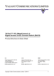
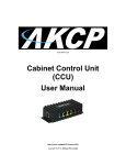
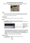
PROception proSAT1EYE Mk2 Digital Satellite TV Control Extender INSTRUCTIONS This product allows you to control a Sky* Digibox digital satellite receiver or Sky+* personal video recorder (PVR) from another room. It is useful where you have wired the output of the Digibox or PVR to one or more remote rooms so that the selected digital satellite channel (or hard disk playback) can be viewed on additional TV sets. The wiring can be as simple as a direct extension cable from the Digibox or PVR to a single remote room described in this leaflet or it can be a feature of a more comprehensive signal distribution system using a suitable amplifier with return path capability. PROception offers a range of compatible multi-way distribution equipment - please see our Web site or literature for details. Compatibility The proSAT1EYE is for use with Sky* digital satellite equipment only and is compatible with all makes of Digibox and Sky+* PVR. Product components PROception proSAT1EYE IN The following guide should assist in case of difficulty. No digital satellite channels available in remote room Check that the signal feed from the Digibox or PVR (RF OUT-2) via the extension cable or distribution system is properly connected to the remote room TV via the coupler. Check that the remote room TV is tuned to the correct channel for your Digibox or PVR output. No terrestrial TV channels Check that the coaxial cable from the aerial is correctly connected to the Digibox or PVR (via the VCR if fitted) as described in your Digibox or PVR user manual. Remote control not working (unable to change channel on the Digibox or PVR from the remote room) Check that the red LED power indicator on the coupler is alight. If not, try the following. n Check that you have enabled the second outlet power supply option in the installer set-up menu, as described under configure the Digibox or PVR on page 2. n Ensure that the coupler is connected as shown in the diagrams, with the female coaxial connector connected to the feed from the Digibox, PVR or amplifier. Remote control will not work if the coupler is connected the wrong way round. n Switch off the Digibox or PVR and disconnect the mains plug. After 10 seconds, reconnect the mains plug and switch the Digibox or PVR on. n Check that there is a direct connection between the output of the Digibox (or PVR) or the distribution amplifier and the coupler with no other parts in line, for example, isolated wall plates. If there are wall plates, check that they are non-isolated. If necessary, replace with nonisolated wall plates as described on page 3. If a distribution amplifier is in use check that it is compatible with the proSAT1EYE kit i.e. that it has an RF return path and provides 9 V DC power at the outputs for infra-red eyes. n Check the cable between the Digibox, PVR or distribution amplifier and the coupler. In particular, check all the coax plug connectors (see page 3). If you have a multimeter, check for the presence of approximately 9 V DC at the incoming cable connection to the coupler. TV Troubleshooting receiver eye Mk 2 coupler 2-Year Guarantee INSTALLATION NOTES Wiring This guarantee covers failure of your PROception product resulting from manufacturing defect within a period of 2 years from the date of supply to the end-user. This guarantee does not cover damage to the product caused by abuse, tampering, defective installation or natural causes such as lightning discharge. Repair or attempted repair, other than by the manufacturer, will render this guarantee void. This guarantee does not affect a consumers statutory rights. If there is no extension cable or distribution system in place already, start by installing coaxial cable (not supplied) between the RF OUT-2 connector on the back of the Digibox or PVR and the remote room, as shown in Fig. 1. Fig. 2 shows the connections required if you already have (or intend to install) a signal distribution system. For the remote control function to work the amplifier must be of the type which has a return path capable of passing remote control signals at 7 MHz. Installation of this type of system is covered in the instructions supplied with the amplifier. Proception Limited, 177-187 Rutland Road SHEFFIELD S3 9PT United Kingdom Web: http://www.proception.co.uk/ e-mail: [email protected] Page 4 PD2011-9035-02 Remote room installation Place the receiver eye on or near the TV in the remote room and connect the coupler into the TV signal cable as shown in the digrams. Ensure that the eye faces into the room and is visible from your viewing position. The self-adhesive Velcro pads can be used to hold the eye in position. Important: If you are using a VCR or other accessory equipment in the remote room the coupler must be connected on the aerial (extension cable) side of the VCR or accessory, not on the TV side. The female coaxial connector of the coupler must face the incoming signal cable and the short flying lead with the male coaxial connector must face the TV equipment side. The remote control function will not work if the coupler is connected in-line the wrong way round. *Sky and Sky+ are registered trade marks of British Sky Broadcasting Group plc. Page 1 Fig. 1 direct extension wiring Tuning and testing Before testing remote control operation ensure that all remote room TV(s) have a channel setting tuned-in to the output channel from the Digibox or PVR. If the extension cable or distribution system is newly installed this tuning will need to be carried out for the first time. Select a digital satellite channel on the Digibox or PVR and tune an unused channel setting on each remote room TV into the satellite programme. (By default the output from the Sky* equipment is found on UHF channel 68, but this can be changed if necessary to avoid interference.) Refer to your TV manual or manufacturers help line or Web site if you are unsure how to retune your TV. Now check that the red LED indicator on the coupler is alight. This confirms that the coupler and receiver eye are receiving power. If this LED is not lit refer to the troubleshooting guide on page 4. Finally test remote control operation by taking the Sky* remote control handset to each remote room and operating it. VCR (optional) Sky* digibox receiver eye RF OUT-1 PROception proSAT1EYE Outlet plates IN TV RF OUT-2 Mk 2 coupler second TV main TV The TV connection in a remote room may use a wall outlet plate. Note that some types of existing outlet plate, particularly the isolated types illustrated, are not compatible with the proSAT1EYE system and will need to be replaced. Replacement plates are readily available from electrical or TV retailers, or DIY stores. The replacement should be a single non-isolated outlet plate. Old isolated outlet plates Alternatively, non-isolated dual TV/radio outlets are also compatible, not compatible with proSAT1EYE provided that they have DC continuity to the the TV connector check this point with your supplier before purchasing replacements. Use of an incompatible outlet plate will prevent power from reaching the coupler (red LED indicator not lit) and this in turn will prevent the remote control function working. TV Fig. 2 example application with distribution system distribution amplifier proAMP104X PROcection IN VCR RF OUT-2 to additional TVs Coaxial plugs Sky* digibox Correct fitting of the coaxial plugs used to make connection to the product is crucial to obtaining the best results from your system. Achieving sound braid and centre connections is important. Any good quality type of coaxial plug is suitable, but note that fitting some types involves a soldering operation. The sequence of diagrams below illustrates how to fit the most common type of plug correctly (this type requires the centre connection to be soldered). Other plugs may vary and some solderless types use a screw clamp connection or spring centre contact. Any specific fitting instructions supplied with your plugs should take precedence over the diagrams here. Failure to solder the centre connection where necessary may result in intermittent or unreliable remote control operation. RF OUT-1 IN TV receiver eye PROception proSAT1EYE FM Mk 2 second TV coupler main TV 16 mm cap inner conductor clamp Configure the Digibox or PVR The purpose of this step is to configure the Digibox or PVR to supply 9 volt power to the remote receiver eye. A distribution system using a mains powered amplifier may or may not require this step - refer to the amplifier instructions for further information. This procedure should be carried out in the room containing the Digibox or PVR (usually at the main TV location). n Switch-on the main TV and the Digibox or PVR, and select a digital satellite channel. n Using the Sky* handset, select the services menu by pressing the SERVICES button and choose the SYSTEM SET-UP option (4). n From the SYSTEM SET-UP option, press 0 then 1, then press the SELECT button on the handset for the INSTALLER SET-UP menu. n Choose the RF OUTLETS option (4) and select SECOND OUTLET POWER SUPPLY. Select ON and then save settings. n Press BACK UP to return to TV viewing. n Check on your main TV that you can see all your terrestrial TV channels and the digital channels that you subscribe to. WARNING: Changing any other settings in the INSTALLER SET-UP menu may cause problems. Page 2 22 mm a) First place the cap over the cable. Strip away the cables outer sheath. Take great care not to cut through the braid wires. Strip away insulation to reveal the inner conductor. b) Bundle the braid wires together and slide the clamp over the cable. trim and solder end of inner conductor to inner contact here connector body outer body c) Dress the braid wires evenly over the clamp. Push cable and clamp into the connector body. Solder the inner conductor to the contact pin as shown. Screw cap and outer body securely together. Page 3