1
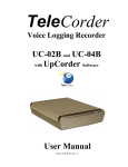
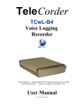
Tele Corder
TC-02F and TC-04F
Voice Logging
Recorder
Tele Corder
User Manual
Version 2.30-F-US, Rev. 3
Table of Contents
Page 1
I. TeleCorder Configurations .................................................................. 3
II. Cable Connections and Testing............................................................ 3
1. Identify the Front and Rear Panel Connections.............................................
2. Connecting to Phone Lines and other Audio Sources....................................
2.1 Connection for 2 channels with TC-02F ...............................................
2.2 Connection for 4 channels with TC-04F ...............................................
3. Power Connection ............................................................................................
4. Preliminary Testing .........................................................................................
5. Installing Software and Connecting to a PC (Win-2000/XP/Vista-32) .......
3
4
4
4
5
5
6
III. Using TeleCorder .................................................................................. 6
1.
Recording Process ............................................................................................ 6
1.1 Setting for Phone Line or Voice Activated Recording (VAR) ............. 7
1.2
VAR Settings ........................................................................................ 7
2.
Setting Channels for Operation in VAR (Voice Activated) Mode.............. 8
2.1
Configuring TeleCorder using a PC...................................................... 8
a. Channel/Port Setup .................................................................. 8
b. VAR Voltage Threshold (Voice Activated Recording)........... 8
c. Turn-Off-Delay Time (VAR Space Time) .............................. 9
d. VAR Timeout ............................................................................9
e. Save or Delete Recordings Less Than 8 Seconds......................9
f. Hardware Information ...............................................................9
g. Date/Time Setting......................................................................9
h. Audio Recording Mode (Quality of Recordings) ......................9
i. Limitation for List Displaying ...................................................9
j. Caller ID Detection Settings......................................................9
k. Volume Balance Setting (Dava) ..............................................10
l. Dava (Digital Automatic Volume Adjustment).......................10
m. Notice for PC Settings .............................................................10
2.2 Setting up TeleCorder using its Built-in Keypad ................................ 10
2.3
Removal of TeleCorder....................................................................... 11
3.
Managing and Playing the Recordings ........................................................
3.1 Managing and Playing Recordings with a PC.....................................
a. Connection.............................................................................
b. Using the Utility Software .....................................................
c. Refreshing the List of Recordings .........................................
11
11
11
11
12
3.2
3.2.1
3.2.2
d. Re-Order the List of Recordings ........................................... 12
e. Find Recordings using Search Criteria.................................. 13
f. Files, Information .................................................................. 13
g. Conversion of Recordings and Saving with a PC ................. 13
h. Print and Save the List of Records ........................................ 14
i. List Delete, Deleting Recordings from TeleCorder .............. 14
j. Hardware, Access to Hardware Sub-menu............................ 14
k. Hardware Information ........................................................... 14
l. Date and Time Setting ........................................................... 14
m. Recording Mode, Select Quality of Recordings......................14
n. Limiting the List of Displayed Recordings ........................... 15
o. Caller ID Detection Settings.................................................. 15
p. Volume Balance Setting (Dava)............................................ 15
q. Lock and Unlock Using Password ..........................................16
r. Modify Password.....................................................................16
s. Built-in Keypad Password.......................................................16
t. Play Recordings from List.......................................................16
Playing Recordings Using the Built-in Keypad............................ 17
Description of Displayed Symbols ............................................... 18
Operational Procedures ................................................................. 18
IV. Privacy .................................................................................................. 20
V. Guarantee & Liability .......................................................................... 20
VI. Specifications ......................................................................................... 20
VII.
Accessories .................................................................................... 21
TSA-3LM
TSA-SLM
T-18
T25-EXT
MOD-SC
MTJ-S2
PZ-2LA
Adapter for connecting to a phone set at handset jack ...........21
Adapter for connecting to a phone set, with on/off switch .... 21
Phone cable with T adapter....................................................21
Twenty-five foot phone line extension cable..........................21
Adapter for converting modular phone plug to mini plug ......21
Converts 2-line modular jack to individual L1 & L2 jacks..... 22
Room Monitoring Microphone ...............................................22
VIII. Contact Information for Support and Service............................... 22
IX.
2
Notes ................................................................................................... 23
TeleCorder V 2.30-F-US, Rev. 3
TeleCorder
Cost Effective Voice Logging Recorder
The TeleCorder is a digital audio recorder that can simultaneously record and play from phone lines or
other audio sources. Recordings start and stop automatically using either phone line voltage sensing or
audio activation. They have an internal hard drive and can be connected to a PC via USB connection.
While the recorder can be used as a stand alone unit, most users find it easier to set-up and use the
TeleCorder with a PC (Win-2000/XP/Vista-32) using the included USB cable and software.
I. TeleCorder Configurations
Model Type
2 Channel
TC-02F
4 Channel
TC-04F
Supplied Accessories
(phone line cables)
2 each # T-18 (18' phone cable
with “T” adapter)
2 each # MTJ-S2 (line splitter)
4 each # T-18 (18' phone cable)
Supplied Accessories
(other)
USB cable, power adapter with AC 110V power cord, CD with
TeleCorder PC software (for Win-2000/XP/Vista-32), and this manual.
If you purchased optional items such as cables and/or adapters for installation to audio sources that
do not terminate in standard RJ11 phone jacks, see the instructions that were provided with the optional
accessories for additional installation and operation procedures.
II. Cable Connections and Testing
1. Identify the front panel components and rear panel connections
Unpack and check the contents of the TeleCorder package. Locate the master password page and keep it in
a secure place.
TeleCorder front view, showing speaker, LCD display and keypad.
TeleCorder V 2.30-F-US, Rev. 3
3
TeleCorder rear view, showing USB jack for connecting to a computer, two modular phone
jacks for connecting to the source of the conversations to be recorded, 5vDC jack to power
accessories, and DIN connector for connecting to output of the supplied AC power adapter.
2. Connecting to Phone Lines and other Audio Sources
TeleCorder inputs require 2-wire analog audio such as from direct connection to analog phone lines,
two-way radios, amplified microphones, telephone handset or headset audio (analog or digital phones,
using direct connection to earpiece audio or optional TSA-3LM or TSA-SLM adapters), etc.
2.1 Connecting audio sources to the 2 channel TeleCorder model TC-02F
The TeleCorder connects in parallel to your audio sources. There are two modular phone jacks on the
back of the TeleCorder Model TC-02F. Each jack is wired for connection to one of the two channels using
the center pair of contacts (as with standard RJ-11 phone jacks). When looking at the back panel, the jack
on the left is for channel one (also called “Port 1”), and the jack on the right is for
channel two (also called “Port 2”). The left jack is also wired for both channels as with
standard RJ-14 phone jacks (see image at left — Ch-1 on inside pins 3+4, Ch-2 on
adjacent pins 2+5). Note: If using the
left jack only for connection to channel
one, there must not be any connection to
pins 2 & 5 as these pins also connect to
pins 3 & 4 on the right jack.
Two T-18 cables (18' phone line
cable with T-adapter, photo at right) are
supplied with the recorder. You can use these or other suitable cables to connect to your
phone lines or other audio sources.
If you wish to record from multiple line analog phones or digital telephone sets, instead of individual
phone lines, the most popular way to connect is with a handset splitter. The handset splitters (such as the
Omnicron TSA-3LM or TSA-SLM) are available from your TeleCorder representative. Your sales
representative can also assist you in selecting other cables or adapters to simplify installation for your
application.
2.2 Connecting audio sources to the 4 channel TeleCorder model TC-04F
Each modular phone jack on the back of the TeleCorder TC-04F has connections for two phone lines
or other audio sources. When looking at the back panel, the jack on the left is for Ports 1 and 2, the jack on
the right is for Ports 3 and 4.
The modular jacks use pins 3 & 4 for the first input (center pair), and pins 2 & 5 for the second input
(see the drawing above left). Each individual input can be referred to as either a Channel or Port.
Connect audio sources for channels one and two using the left jack as with instructions for the two
channel TeleCorder (see page 4 “2.1”), and channels three and four to the right jack in a similar manner.
The TC-04F is supplied with two of the MTJ-S2 splitters (see image on page 5) to provide individual jacks
for each input and four T-18 cable sets for connecting to phone lines.
4
TeleCorder V 2.30-F-US, Rev. 3
If connecting to telephone sets where a channel will be
recording all conversations on a particular phone regardless of
what line they are using, instead of recording from a phone line
where all conversations on the line will be recorded regardless
of which phone is using the line, you should make connections
to the phone using adapters such as the Omnicron TSA-3LM
or TSA-SLM or by directly connecting to the earpiece audio
connections inside of the phone (both sides of a conversation
are present at the earpiece).
If it is not convenient or possible to install using standard
modular jacks, identify the pair of wires for each line or audio source and connect in parallel to each
individual input on the TeleCorder.
With bundled phone wiring, you must first identify the line pairs among the wiring cables and then
connect the wires from the TeleCorder inputs to these pairs. Equipment and wiring diagrams may be required
to expedite proper installation. Check with your phone or wiring provider for assistance as needed.
3. Power Connection
Power Connection should be made after connecting telephone cables
to the audio sources that you will be recording. Using the provided power
adapter (photo at right), plug the permanently attached cable into the round
connector on the back of the TeleCorder and use the provided 110V AC
cable to connect the power adapter to a standard 110V AC outlet. Since the
TeleCorder is designed to be in service 100% of the time, there is no power
on/off switch.
To turn it off, unplug the power. To turn it on, plug it in.
4. Preliminary Testing
Normal Operation: After the above connections are completed, check the displayed status on the LCD.
z Text will be displayed on the LCD display a few seconds after external power is applied.
z With no activity on any of the TeleCorder inputs, the display will show TeleCorder, date and time.
When inputs are active, the top line of the display will show: Recording and which inputs are active. By
default, channels are set to Voice Activated Recording (VAR). If any TeleCorder inputs are connected to
standard phone lines, these channels could be triggered by noise on the phone lines between calls. Use
either the supplied PC software, or front panel buttons, to set phone line channels for voltage sensing
start/stop.
TeleCorder V 2.30-F-US, Rev. 3
5
5. Installing Software and Connection to a PC (Win-2000/XP/Vista-32)
Install TeleCorder software from the CD included with your recorder prior to connecting the supplied
USB cable from the recorder to the USB port on your computer.
1.
Insert the CD into the drive on your PC. If it does not auto
run to show install procedure, look at files on the CD using file
manager and open “SetupTeleCorder.exe” file. Follow on
screen instructions. If your PC is running Windows XP or Vista32, you may be asked for Microsoft signature (screen shot at
right). Select continue until installation is finished. The
TeleCorder program will now be installed in your
computer, be listed under Programs, in Control Panel
add/remove programs, and there should be an icon on the
desktop for the TeleCorder (image at left). If you try to run the
TeleCorder program without a TeleCorder connected to your PC
via the USB connection cable, or if the TeleCorder power is off,
the software will not run. You will see “ERROR: No
TeleCorder device connected!”.
2.
If your TeleCorder is not already powered On, connect it to AC
power and wait for it to display time and date. Since the TeleCorder is
normally left On at all times, there is no power On/Off switch. To turn it
Off, unplug the power cord. Connect the supplied USB cable (photo at
right) from the USB port on the back of the TeleCorder to a USB port
on your computer. The first time you connect the TeleCorder to your
computer, your PC should display “New Hardware Found” message,
search for and install the required driver software (FTD2XX.dll), if the
software was previously installed (see above).
If connecting a TeleCorder to your PC that was previously used with a
different TeleCorder, you may receive a pop-up message telling you that it
has “Found New Hardware, FTD2XX device, installing — Files Needed”,
type the path to the folder where the driver was previously installed (such
as: C:\Program Files\TeleCorder\TeleCorder\TeleCorder.exe), or the path to the driver folder on the CD
supplied with your TeleCorder (such as: E:\Driver, where E is the CD drive on your PC containing the
TeleCorder CD).
3.
Run the TeleCorder program by clicking on the icon on your PC desktop that was created when the
program was installed or from the programs list. Refer to manual section III (below) for detailed
information.
III. Using TeleCorder
1. Recording Process
When connected to standard telephone lines, the TeleCorder will automatically record the telephone
number called in or dialed out, time duration of the call and the voices of the conversation. You don’t need
to change your procedure for making or receiving your calls. Nevertheless, the following points should be
considered. When connected to phone lines, channels should be set to start/stop recording using the voltage
sensing mode, not the VAR mode (hardware set-up from key-pad, or Hardware screen using a PC).
6
TeleCorder V 2.30-F-US, Rev. 3
1)
If Caller ID numbers are not displayed, confirm with your telephone company that your phone
lines have the caller ID feature enabled. Otherwise, there will not be caller phone numbers recorded and
displayed when managing the recordings. If you are connected to telephone handset audio, the recorder will
not show caller numbers and will only show dialed out numbers if the handset has standard DTMF tones
when dialing. Also check to be sure phone line channels are set for voltage sensing, not for VAR start/stop.
2)
Always wait to answer a call until after the second ring so that the phone number from the calling
party can be received and stored with the recording.
3)
When channels are set to start and stop recording using voltage sensing, outgoing calls will not be
saved unless they are longer than 8 seconds and contain a minimum of 3 dialed digits (DTMF tones). This
feature minimizes false recordings and does not apply when using Voice Activated Recording (VAR).
1.1 Setting for Phone Line or Voice Activated Recording (VAR)
When you first connect a new TeleCorder, default settings for all channels will be for Voice
Activated Recording (VAR). Channels connected to phone lines should have their start/stop mode changed
to the voltage sensing start/stop mode. In this mode, instead of monitoring audio levels, the recorder will
monitor for DC voltages on the selected inputs to indicate on-hook and off-hook status. The phone line
voltage is high when the circuit is not in use and will drop to a lower voltage when it is being used. Any
channels set for on-hook/off-hook voltage sensing that are not connected to a phone line will not show any
recordings due to the lack of the DC voltage changes that are required to initiate a recording in this mode.
If you connect any of the TeleCorder inputs to audio sources that do not have standard on-hook/offhook voltages, these channels must be set for audio or voice activated recording (VAR).
1.2 VAR Settings
Recorder channels set for the VAR mode will detect the voice level on the line to start a recording. It
will start recording when a preset audio level is reached (normal conversation levels), and stop after the
audio drops below this threshold (no sound other than weak background noise) for a preset period of time.
The length of quiet required for the recording to end is called “turn-off-delay”.
Phone Line Recording
Voice Activated Recording (VAR)
Requirement
to Start
Phone Line DC voltage lower
than the threshold (<20v DC)
Audio level on input is loud enough or louder than
preset threshold required to start recording
Requirement
to Stop
Phone Line DC voltage higher
than the threshold (>20v DC)
Audio level is lower than preset level required to
continue recording for the selected turn-off-delay
Recording from standard
Analog phone lines
1. Radio recording, broadcast or two-way
2. Amplified microphone
3. Audio picked up from handset or headset of
analog or digital telephone set (single or multiline phone)
4. Analog phone line recording where DC voltage
sensing cannot be used
1. DC Voltage Threshold:
(This threshold is preset in the
TeleCorder through hardware
components and cannot be
changed via software).
1. VAR or Off-Hook Mode for each channel
2. Threshold in 4 levels
3. Turn-off-delay/VAR space: (4, 12, 32, or 100
seconds)
4. VAR Time-Out to limit long recordings and start a
new recording: (20, 40, 60, or 120 minutes)
Suggested
Uses
Parameters
TeleCorder V 2.30-F-US, Rev. 3
7
2. Setting Channels for Operation in VAR Mode
You can use either your PC or the keypad built into the TeleCorder to select Phone Line recording or
VAR mode, and to change and confirm these and other operating parameters.
2.1 Configuring TeleCorder using a PC
Using your PC with the TeleCorder program running, select Hardware from the main screen. You
will open the Hardware Information screen as shown here. From this button you will gain information
about the TeleCorder including version number, capacity, media’s usage, recorded call items, deleted call
items, etc.
a.
Channel/Port Setup: Each channel (Port) in the recorder can be set to start and stop recording using
either audio activation (VAR) or voltage sensing. Channels showing a check mark in the boxes labeled
Port 1, Port 2, Port 3, or Port 4, are set for VAR recording. Channels with no checkmark indicate they
are set for phone line recording. For any channel you want to start/stop recording using the phone line
voltage sensing mode, click on the box for that channel to remove the check mark, then click the Write
Hardware button to confirm any changes. With 2 channel TC-02F, disregard Port 3 and Port 4 settings.
b.
8
VAR Voltage Threshold: Set the threshold level to match the audio level on your audio source.
L0: Extra Sensitive, suitable for weak audio sources with low background noise level: (for
example, with weak earphone or line-out recording).
L1: High Sensitivity, suitable for normal line level audio sources with low background noise
levels: (normal phone handset earpiece audio or weak speaker of radio).
L2: Mid Sensitivity, suitable for higher than normal audio levels and/or higher background noise
levels: (for recording from a noisy phone line when voltage sensing cannot be used due to nonstandard voltages or with normal speaker audio from a radio).
L3: Low Sensitivity, suitable for very high audio levels, and high background noise levels.
Recording may stop if audio levels are too weak: (phone recording with non-standard and very
noisy DC voltages, or extra loud radio audio).
TeleCorder V 2.30-F-US, Rev. 3
After making changes, click the button labeled Write Hardware to confirm any changes. You may
be asked to quit the program and try again. You may also need to un-plug and re-connect the TeleCorder
power or USB cable to successfully change the TeleCorder operating parameters.
c.
Turn-Off-Delay Time (VAR Space Time): If any channels have VAR selected for recording
start/stop, also select one of the four turn-off-delay options (VAR Turn Off Delay): 4, 12, 32 or 100
seconds. This setting will help to prevent recordings from ending during quiet periods. Click the Write
Hardware button to confirm any changes.
d.
VAR Timeout: If any channels have VAR selected for start/stop, set the timeout to one of the four
choices: 20, 40, 60 or 120 minutes. This setting will limit the maximum length of a recording for easier
management of long conversations or for when recording from broadcast radio where pauses may not be
long enough to separate individual recordings using VAR for start/stop. If a recording reaches the
maximum length of time that you select for VAR TimeOut, that recording will end, and a new recording on
that channel will begin. Click the Write Hardware button to confirm any changes.
e.
Save VAR and Outgoing Calls Less than 8s or Outgoing Calls with Less than 3 DTMF Codes:
Click on this option to place a check mark in its box if you want to save recordings that are less than 8
seconds long. If this box is not checked, VAR recordings shorter than 8 seconds, and outgoing telephone
calls (using voltage sensing for start/stop) with less than 3 DTMF digits, will not be saved.
This setting is normally used if external noise causes frequent and unwanted false audio activated
recordings, or if telephone line testing produces short off-hook conditions that are not associated with actual
phone line usage. It is normal to record all activity on the monitored circuits. Use care when setting to delete
short recordings. This setting can only be changed from the PC. It cannot be changed from the units keypad.
f.
Hardware Information: Click on this box to show information about your TeleCorder: hardware
version, model type, number of calls recorded, number of calls deleted, total length of all recordings (in
hours, minutes and seconds), total length of deleted recordings, and percentage of storage space used.
Information displayed for number of files and duration is for files shown on the current list on the PC.
g.
Date/Time Setting: Click on this box to copy the date/time setting from your PC to the TeleCorder.
h.
Audio Recording Mode: From this sub-button you can set the quality of recordings.
Mode 0 --- Large file, good audio.
8bit linear PCM mode used in the 1st generation recorders.
Mode 1 --- Tiny file, poor audio.
2bit ADPCM mode.
Mode 2 --- Small file, good audio.
3bit ADPCM mode. Default mode set from factory.
Mode 3 --- Large file, best audio.
8bit nonlinear PCM mode.
i.
Limitation for List Displaying: From this sub-button you can set the list display features to speed up
the list refresh process or to have more items displayed in the lists of recordings shown on your PC in the
main TeleCorder program screen. The default setting is 2000 for fastest speed. You can select a different
number, such as 10000, 32768 or 65536, respectively. This selection is saved in software, not as a hardware
setting.
j.
Caller ID Detection Settings: From this sub-button you can set (turn on/off) the caller ID detection
features.
Pre-Ring DTMF Detection: If the local caller ID mode is DTMF and sent before the Ring, you
must turn this feature on. Otherwise, if erroneous caller numbers are
sometimes received, you should turn this feature off.
TeleCorder V 2.30-F-US, Rev. 3
9
Pre-Ring FSK Detection: If the local caller ID mode is FSK and sent before the Ring, you
must turn this feature on. Otherwise, if erroneous caller numbers are
sometimes received, you should turn this feature off.
Forced FSK Between Rings: If your caller ID signaling is FSK and sent between the rings, you
must turn this feature on. This is the normal setting for North America.
k.
Volume Balance Setting (Dava): For recorded audio in the recording mode 1, 2, or 3 (see above) the
player can provide Dava --- Digital Automatic Volume Adjustment capabilities. This is done in software,
not hardware. There are 2 possible settings.
Dava for File Conversion: This setting is normally used to enable Dava converting batches of files
to wave files.
Dava Depth for Play and File Conversion: This setting can provide better audio quality but less
balance in audio levels. This switch will take effect both for playback of
recordings and for batch file converting of recordings to wave files.
l.
Dava:
If the volume levels of the 2 sides of a conversation are different, or if the line quality is not
well adjusted, the Digital Automatic Volume Adjustment (Dava) function will amplify the lower or
far side to more closely match the level of the stronger or near side of a recorded conversation
during playback. Since background noise will also be amplified together with the sound, there will
be a compromise to permit weak voices to be played at higher levels without raising background
noise levels to objectionable levels.
m.
Notice for PC settings:
Some of the above settings must be locked into the TeleCorder hardware by restarting the
recorder. If this is the case, you will see a message to restart the recorder (unplug power from
TeleCorder, wait 10 seconds, and re-connect to power). After any of the above settings are
changed, they will not take effect until the recorder is restarted by turning off or disconnecting AC
power to the TeleCorder, waiting a minimum of ten seconds, and powering the TeleCorder back
on. Any changes made in software should now be locked into the recorder’s internal memory.
After the settings have been changed, check to make sure the recorder is functioning
as expected.
2.2 Setting up your TeleCorder using the built-in HandyPlayer
See section 3.2 for more detailed descriptions of HandyPlayer buttons and operation.
Using the 0 Setup key on the HandyPlayer, enter into the setup mode. When in the setup mode,
parameters to change will be underlined. Use the 4 or 5 keys to change which character is highlighted and
the 2 and 8 key to change the value of the highlighted character. Use the bottom right key to save changes
or the bottom left key to quit.
1. There are 4 setup modes provided on the HandyPlayer.
The setup items on the HandyPlayer are listed as follows:
a. Date/Time/Recording Mode
b. Password
c. Language for display
d. VAR Channels (two with model TC-02F, four with TC-04F)
The channels are listed from 1 to 4 (P1, P2, P3 and P4) as “xxxx”,
1 for VAR, 0 for non-VAR
e. VAR Threshold
f. VAR Delay Time
g. VAR TimeOut
Set individual VAR options as required to match the required recording parameters.
10
TeleCorder V 2.30-F-US, Rev. 3
2. Notes
a. To avoid interruption of active recordings, you should only set the above items while the
recorder is idle. Wait until no channels are active or unplug inputs prior to changing settings.
b. The above settings must be locked into the TeleCorder hardware by restarting the recorder.
After any of the above settings are changed, they will not take effect until the recorder is
restarted by turning off or disconnecting AC power to the TeleCorder, waiting a minimum of
ten seconds, and powering the TeleCorder back on. Any changes made in software should
now be locked into the recorder’s internal memory.
c. After the settings have been changed, check to make sure that the recorder is functioning as
expected.
d. The recorder listens for outgoing numbers dialed using DTMF/touch-tone signaling and stores
them with the recording. It is possible for it to document and record false phone numbers
when the recorder is in the VAR mode (particularly when recording broadcast radio music
where the audio can mimic sounds of dialing). To avoid collecting and recording these
erroneous numbers, you can use the PC interface to disable storing of dialed digit signaling.
2.3 Removal of TeleCorder
Follow the installation procedure outlined above in reverse order.
3. Managing and Playing the Recordings
3.1 Managing and Playing Recordings with a PC
The TeleCorder does not require a PC for setup, recording or playing back recorded conversations.
However, you may find it more convenient to operate it from a PC. With a PC you will also be able to
convert recordings to standard wave files and archive them to storage on your PC. Playing selected
recordings from a PC will not inhibit recording or simultaneous playback of recordings from the
TeleCorder using its built-in HandyPlayer.
The PC does not have to be On or connected to the TeleCorder for it to function. Connecting the
TeleCorder USB cable to your PC and/or turning the PC power on or off will not stop the recorder from
functioning. You can also disconnect the TeleCorder USB cable from a PC and connect it to a different PC
without interrupting the TeleCorder operation.
a. Connection:
Connect the TeleCorder to the USB port in your PC using the provided USB cable. The PC used for
managing/playing must be equipped with an available USB port, sound card as well as speakers, and use
Windows® operating system 2000/XP/Vista-32.
b. Using the Utility Software:
You must install the supplied utility TeleCorder Manager/Player software from the provided disk to
your computer prior to being able to manage the recorder from the PC or playing recordings through PC
control (see manual page 6, Section 5, Installing Software and Connecting to a PC). The first time that you
connect your PC to your TeleCorder, you may be asked to install the USB device driver. This driver should
have been copied to your PC during install. If not, use the CD supplied with your TeleCorder to install the
required USB driver following the instructions displayed on your computer.
After installing the software, place a short cut icon on the desktop for easy access (if it was not
automatically installed during install). Click the software icon or the short cut created during the install and
the recordings will be listed in the main window (as shown in the following screen image). The listed
information includes the ITEM or sequential recording number, the PORT that was the source of the
recording, CALLER ID NUMBER or DIALED NUMBER (if available when the recording was made),
DATE and TIME the recording started, and the DURATION of each recording in minutes and seconds. All
records are listed in the reverse order so that the most recent recording is indexed as item number 1.
You can drag the slider bar on the right side of the display window to view the un-displayed part of
the list. On the lower part of the form, there are buttons for Refresh, Re-Order, Find, Files, Hardware,
Lock/Unlock, and Exit.
TeleCorder V 2.30-F-US, Rev. 3
11
These buttons provide the following functions:
c.
Refresh:
Refresh the list to display the latest recordings in the TeleCorder at any time.
d.
Re-Order:
User can select one of the following ordering rules to re-order the list.
1. Recorded – provides a list based on the time recordings ended.
2. Starting Time – provides a list based on the time recordings started.
3. Record Duration – provides a list based on the length of recordings.
4. Channel Number – provides a list based on the channel number.
5. Un-Answered List – provides a list of calls on phone lines that were not answered.
(Un-Answered Listing is not supported with TC-02F & TC-04F)
12
TeleCorder V 2.30-F-US, Rev. 3
e. Find: You can search the records using a specific caller number or dialed number and/or within a
date range that you input.
In the dialogue box, you can enter search conditions such as date range, digits from a phone number
such as 010, 6256 etc. The searched results will display on the screen after you select “Start Search”.
You may also enter only a start and stop date range and all of the recorded items during the date range
will be displayed.
The recorded items after a search can be played or used for further searching and for making Wave
files in a batch job. Refer to the File Copy for more details.
f.
Files:
This button provides the following functions for the displayed files.
g.
Conversion of recordings to WAVE files and saving to PC
Wave Files are a widely used and supported multimedia File Format for the PC and other computer
systems. Since the TeleCorder uses a unique format for saving the recordings in digital form, digitally
converting them is a better way to exchange information with other systems that do not have TeleCorder
software. You can use your PC to send audio recordings via e-mails or make backup CDs without worrying
that others may not be able to play them.
There is an option to save individual recordings when they are selected for playback (select the
button with red dot from playback menu).
There are 3 choices:
z
All ---- Copy all of the records listed in the form, including both the ones displayed and the
ones not displayed. This button would be used to copy all recordings retrieved by a search.
TeleCorder V 2.30-F-US, Rev. 3
13
z
Last Month ---- The software will search again from all of the records in the TeleCorder
within the 1st and 31st of last month, then perform a batch job to generate the wave files. This
function is specially designed for users to make monthly backups.
z
Last Week ---- The software will search again from all of the records in the TeleCorder
within the last week, and then it will do a batch job to generate the wave files.
z
Help ---- Produces a window with more detailed information about converting to wave files.
All the generated files will be placed under the file folder of WaveFolder 00-99 using the present path.
The last two numbers in the folder name will be produced automatically by the software. You can also
browse the files within all the WaveFolder XX folders. The newest folder would be named with the highest
number.
Each file refers to a unique record. The name of each file contains date and time of the call, caller or
dialed number such as File P2 10-26-04 09=11=10 DIAL TO 18609280377.WAV (recording made on
TeleCorder Port 2 on October 26th, 2004 at 09:11:10, call was outgoing and dialed to 1-860-928-0377) .
The files are suffixed with “.Wav”. You can change the file names as required, but you should not change
the suffix unless there are special requirements.
h.
Print and Save the List of Records:
The displayed list on the screen can be printed or saved
into a “.txt” file. No matter how the call list is re-ordered, the searched and sorted list can be printed.
i.
Delete Recordings: The recorded calls can be selectively or entirely deleted. To avoid unauthorized
deletion, the password must be entered before deleting recordings. If no password has been set, you will
need the master password that was supplied with your TeleCorder. Options are to delete the most recent
recording, all recordings, or a selected range of recordings. Deleted recordings cannot be recovered.
j.
Hardware:
From this button you can access all of the recorder’s hardware and information settings:
k.
Hardware Information:
From this sub-button you will gain information about the TeleCorder
including version number, capacity, media’s usage, recorded call items, deleted call items, etc.
l.
Date/Time Setting:
m.
Recording Mode: From this sub-button you can read or set the quality of recordings.
Mode 0 --- Large file, Good audio.
14
From this sub-button you can read and set the real time clock in the recorder.
TeleCorder V 2.30-F-US, Rev. 3
8bit linear PCM mode, 28.8 MB/hour
Mode 1 --- Tiny file, Poor audio.
2bit ADPCM mode, 7.20 MB/hour
Mode 2 --- Small file, Good audio.
3bit ADPCM mode. Default mode set from factory, 10.84 MB/hour
Mode 3 --- Large file, Best audio.
8bit nonlinear PCM mode, 28.8 MB/hour
n.
Limitation for List Displaying: From this sub-button you can select the number of recordings
that will be listed on the PC. To speed up the list refresh process, the default setting is 2000. This setting
will cause your PC to display the most recent 2000 recordings after a refresh. You can select a different
number, such as 10000, 32768 or 65536. This selection is saved in software, not as a hardware setting.
o.
Caller ID Detection Settings: From this sub-button you can set (turn on/off) the caller ID
detection features.
Pre-Ring DTMF Detection:
If the local caller ID mode is DTMF and sent before the ring, you
must turn this feature on. Otherwise, if erroneous caller numbers are
sometimes received, you should turn this feature off.
Pre-Ring FSK Detection:
If the local caller ID mode is FSK and sent before the ring, you must
turn this feature on. Otherwise, if erroneous caller numbers are
sometimes received, you should turn this feature off.
Forced FSK Between Rings:
If your caller ID signaling is FSK and sent between the rings, you
must turn this feature on. This is the normal setting for North America.
p.
Volume Balance Setting (Dava):
For recorded audio in the recording mode 1, 2, or 3 (see above)
the player can provide Dava --- Digital Automatic Volume Adjustment capabilities. This is done in
software, not hardware. There are 2 possible settings.
Dava for File Conversion:
This setting is normally used to enable Dava when converting batches
of files to wave files.
Dava Depth for Play and File Conversion: This setting can provide better audio quality but less
balance in audio levels. This switch will take effect both for playback of
recordings and for batch file converting of recordings to wave files.
Dava --- If the volume levels of the 2 sides of a conversation are different, or if the line quality is not well
adjusted, the Digital Automatic Volume Adjustment (Dava) function will amplify the lower or far side to
more closely match the level of the stronger or near side of a recorded conversation during playback. Since
background noise will also be amplified together with the sound, there will be a compromise to permit
weak voices to be played at higher levels without raising background noise levels to objectionable levels.
TeleCorder V 2.30-F-US, Rev. 3
15
q.
Lock/Unlock:
Lock:
Unlock:
This button provides access to security settings for the recorder.
After the recorder is locked, it will ask the user to input a password each time a
user tries to access the recorder. A password must be entered to use this function.
To unlock the recorder so that a password is not needed, the password must
be entered.
r.
Modify Password:
The recorder comes with a factory-set password, which is in the machine code
that is set by its hardware and cannot be changed. This password is written on a sheet that comes with the
recorder and will be an effective password forever (keep this password in a secure place). The TeleCorder
also allows you to set a second password that can be easier to remember. Use the Modify Password button
to set a second password of 6-8 characters. You must enter the factory-set password prior to being given the
opportunity to add a second password. After the second password has been set, it will have the same effect
as the first password. The new password is also stored in the hardware of the recorder so that it will work
even if the recorder is connected to, and used with, another PC. Use UnLock to disable 2nd password.
s.
Built-in Keypad Password:
The built-in keypad uses a 4 digit password that is stored in the
recorder hardware. Although this password can be modified using the keypad, this button provides a second
way to set the keypad password. Set it to “0000” and you will no longer be asked for a password.
t.
Play Recordings from List: When playing recordings, buttons in the lower part of the screen will
be swapped to a new set of buttons that are used to control various playback functions, as shown in the
following image. The playback will start immediately. If it is a long recording, the playback function
buttons will not show until the recording has been completely transferred from TeleCorder to the PC.
16
TeleCorder V 2.30-F-US, Rev. 3
The functions of these buttons are:
Dava: Click the “aVa” button and the recorded audio will be processed and played from the
beginning with Automatic Volume Adjustment. You may also drag the horizontal slider bar to move the
playback start point.
Save as Wave File:
Click the button with a red dot to save the selected recording to your PC. The
following image shows the dialogue box you will see if you click the red dot make wave file button in
the dialogue box. The recordings will be saved by default with a file name containing port number, date
and time of the call, and caller ID or dialed numbers. There will be an option to rename the file when
converting to a wave file.
Rewind:
Click the button with the arrows pointing to the left to jump backward in playing time.
Pause/Play:
Click the button with two vertical lines to pause playback. Click again to resume.
Fast Forward:
Click the button with arrows pointing to the right to jump forward in playing time.
Stop: Click the button with square box to end playback.
3.2 Playing Recordings Using the Built-in Keypad
Numbers on the keypad buttons are for entering a password.
The keypad buttons are also used for setting up most TeleCorder operating parameters, selecting
recordings to play, controlling playback, turning display backlight On/Off, adjusting internal speaker
volume (two levels), and displaying the help menu.
You can listen to the recordings by using either the small speaker that is built into your TeleCorder,
or, by connecting an external speaker or headset to the 3.5mm monaural mini-jack that is located on its left
side of the recorder near its built-in speaker. Browsing and playback using the built-in keypad is limited to
the most recent 2000 recordings.
TeleCorder V 2.30-F-US, Rev. 3
17
HandyPlayer keypad buttons provide the following functions:
Turn the LCD backlight On and Off
Jump down 3 in list of recordings when browsing, advance selected item in set-up
Help menu On/Off
Down 1 when browsing the recordings, backward when playing or programming
Play a selected recording, pause when playing
Up 1 when browsing the list of recordings, forward when playing or programming
View list of recordings
Jump up 3 in list of recordings when browsing, decrease selected item in set-up
View list of recordings
Stop playing recordings, return to startup screen
Volume adjustment (two levels) when playing, enter setup when not playing
Stop playback, accept when setting or entering password
3.2.1 Description of the displayed symbols
Top line shows the index number, date, time, and length of recording in seconds.
00002 07-15 00:14 0086
Middle line shows the current selection including any caller ID or touchtone digits.
18005551212
▌8609280377
(# indicates outgoing call)
( ▌indicates an incoming call)
3.2.2 Operational Procedures
Step 1: Make sure the TeleCorder recorder is powered on.
Step 2: The startup message should be displayed on the LCD.
Step 3: If no function keys are depressed for 10 seconds, the LCD will display the date/time message.
If any of the function keys are pressed, the player will show the list of recordings for browsing or
ask for a password prior to showing the list of recordings. If the 0 key is pressed on the HandyPlayer, it
will go into a set-up mode to change the date/time/recording mode and password for the recorder.
18
TeleCorder V 2.30-F-US, Rev. 3
Password Check
Setting Password
Setting Date, Time, and recording mode (0, 1, 2=default, or 3)
Setting Language (E=English, C=Chinese)
Information displayed while browsing
Current
Item #
Date & Time
Duration (Sec)
Currently directed item:
Phone number
Previous item
Next item (Empty)
Outgoing call
Information displayed while playing
Moving slide and timing showing play progress!
Step 4: If there are no recordings in the recorder, it will display an empty item with zero length.
If you press the “▲” button it will return to start-up mode automatically.
TeleCorder V 2.30-F-US, Rev. 3
19
IV. Privacy
When recording conversations you must consider the privacy of all individuals that are part of the
conversation. Some countries require notification of one or all participants in recorded conversations.
Check your local and national legal obligations on this and other issues concerning the use of the
TeleCorder.
In the United States, the Federal Government requires that at least one person that is a participant in a
conversation knows that it is being recorded. Some states require all parties to be aware that a conversation
is being recorded. The manufacturer and retailer accept no liability for the loss of data, the possible
consequences thereof, or general misuse of recorders.
V. Guarantee & Liability
Your TeleCorder has a 12-month limited manufacturer guarantee. The guarantee is effective only for
normal use. It is not valid under exceptional environmental or operational conditions, such as extreme
temperatures or humidity levels, nor in the event of a lightning strike or similar damage from excessive
voltages on connections. The guarantee is not valid if it has not been handled properly, for example, if it
has been damaged by dropping. To qualify for the guarantee, contact your supplier or the manufacturer.
The guarantee does not cover costs of sending to or from the supplier or manufacturer, and does not cover
any expenses resulting from the failure of TeleCorder.
Correct functioning of the TeleCorder cannot be guaranteed under all conditions. The TeleCorder
supplier and manufacturer cannot and will not accept any liability for loss of information or other damages
due to the use or misuse of the TeleCorder. Suppliers and the manufacturer are not a source of official
interpretation of laws and shall not be construed as a source for making decisions.
VI. Specifications (subject to change without notice)
Number of Channels: Two with TC-02F, four with TC-04F
Capacity (hours): 3,600 with TC-02F and TC-04F
Security: Password (3): Master, PC, and HandyPlayer
Digital Encoding: Voice quality good, A-law PCM mode (25% as specified, 28.80 MB/hour)
Voice quality OK, G.726 2bit ADPCM mode (as specified, 7.20 MB/hour)
Voice quality very good, G.726 3bit ADPCM mode, (75% as specified, 10.84 MB/hr.)
Voice quality excellent, 8bit linear PCM mode (25% as specified, 28.80 MB/hour)
Frequency Response: 340-3,400Hz, +/- 3db
Sampling rate: 8,000Hz
Recording Trigger: Off-Hook (phone line voltage sensing for start/stop, <20vDC>)or VOX/VAR
(audio activated for start/stop – 0.8Vpp, 0.4Vpp, 0.2Vpp, or 0.1Vpp)
Line Impedance AC: >10k ohm
Line Impedance DC: >10M ohm
Ringer Equivalence: AC-REN – 0.6B
Caller ID: FSK/DTMF
Dialed Number: DTMF
Internal Storage: Hard Drive
Storage Limits: 65,536 files, 3,600 hours - with 40 gig hard drive or 7,300 hours - with 80 gig hard
drive. Automatic overwriting of oldest files when limits are reached
Display: Built-in 2-1/8" x 3/4" backlit LCD, or PC with included USB cable and software
Size: 6-5/8" wide x 8-1/2" deep x 2-3/8" high, 170mm x 220mm x 55mm, (not including cables)
Weight: 3.7 lbs., 1.6kg (not including cables and external power supply)
Power Requirements: 100-240V AC external power supply with 110V AC cord for U.S.A., 15W
Approvals: FCC (TeleCorder Model F4, US:BCXRT06BF4), UL, CE
Guarantee: Twelve month, limited
Manufactured by: Beijing ChangXing Co., Ltd., China
Distributed in U.S.A. by: Omnicron Electronics, Putnam, CT U.S.A.
20
TeleCorder V 2.30-F-US, Rev. 3
VII. Accessories
Contact tour TeleCorder representative if you have questions or for assistance in selecting
the proper cables or adapters for your application.
TSA-3LM — Telephone Handset Supervisory Adapter
The TSA-3LM is the easiest way to monitor
conversations on individual telephones. It can be used to provide
a simple method of connecting the recorder to telephone handset
or handset audio.
It can be used with most telephone styles that have a
standard modular handset or headset jack (RJ-10, 4P4C).
Simply connect one end of the cable in series with the
telephone handset or headset cord and connect the other end
to the recorder. The TSA-3LM has a 25' output cable that can
be extended with the T25-EXT or other suitable phone line
extension.
TSA-SLM — Telephone Handset Supervisory Adapter, with
on/off switch
The TSA-SLM provides all of the functions and features of the
TSA-3LM with the addition of an on/off switch that is used to
disconnect the telephone audio from your recorder when you do not
want your conversation recorded. The TSA-SLM has a 25' output
cable that can be extended with the T25-EXT.
T-18 — Telephone Line Cable with T Adapter
This multi-purpose cable assembly can be used to
connect between two RJ-11 (single line) or RJ-14 (two line)
phone jacks. It is 18' long and comes with a T adapter. The T
adapter is used when you do not have an extra jack for the
cable connection. It will convert a single phone jack into two
parallel jacks.
T25-EXT — Twenty-Five foot Phone Line Extension Cable
Provides a 25' extension for standard RJ-11 or RJ-14 phone
cables with a modular plug on one end and a modular jack on the other
end.
MOD-SC — Converts modular phone cable to mini-plug
The MOD-SC is used when you have a cable with standard RJ-11
single-line telephone type plug that you need to connect to audio from
equipment with 3.5mm mini-plug jack. It has an RJ-11 jack on one end and a
3.5mm monaural mini-plug on the other end.
The MOD-SC is typically used to connect modular telephone line cables
provided with digital audio recorders to the audio output of a radio receiver.
TeleCorder V 2.30-F-US, Rev. 3
21
MTJ-S2 — Converts 2-Line RJ-14 Jack into Separate RJ-11 Single Line Jacks
This adapter/cable assembly splits a 2-line RJ-14 circuit/jack into
two RJ-11 jacks (Line-1 on left and Line-2 on right). Typically used with
the two line jacks on TeleCorder recorders.
PZ-2LA — Pressure Zone Room Monitoring Microphone with Line
Level Output
The Omnicron PZ-2LA Microphones are Pressure Zone Microphones® designed for
meeting and conference recording. They look like a switch, not a microphone, so as not to draw
attention.
Like other Pressure Zone Microphones, they use a
miniature microphone capsule mounted near a sound reflecting
plate. In this zone, direct sound from the source combines in phase
at all frequencies with reflected sound. The benefits are many: 6
dB more sensitivity, 6 dB less noise, a wide smooth frequency
response free of phase interference, excellent clarity, and
consistent pickup anywhere around the microphone. A built-in
amplifier provides a high level output. Power for the amplifier in
the PZ-2LA is provided by an AC power adapter which is
supplied with the PZ-2LA microphone. The PZ-2LA comes with a
cable for connecting to the RJ-11 jack on TeleCorder digital audio
recorders. If the microphone is located more than 25' from your
recorder, standard RJ-11 telephone extension cables can be used.
One twenty five foot (25') extension cable is supplied with each
PZ-2LA.
VIII. Contact Information for Support and Service
Manufactured in China by: Beijing ChangXing., Co., Ltd., www.telecorder.com
Distributed in USA by:
Omnicron Electronics
581 Liberty Highway
Putnam, CT 06260
E-Mail: [email protected]
Web: www.omnicronelectronics.com
Phone: (860) 928-0377
Fax: (860) 928-6477
22
TeleCorder V 2.30-F-US, Rev. 3
IX. Notes
1.
The recorder comes with a factory-set master password, which is in the machine code that
is set by its hardware and cannot be changed. This password is written on a sheet that
comes with the recorder and will be an effective password forever (keep this password in
a secure place). If you lose the master password, your TeleCorder may have to be returned
to a factory authorized service facility to determine what the password is from its internal
hardware.
2.
Avoid shaking the TeleCorder, and keep it in an environment with moderate temperature
and humidity that is suitable for electronic equipment.
3.
There are no user-serviceable parts inside of the TeleCorder. Refer servicing to qualified
service personnel. If the clock does not maintain the correct time and date without external
power, an internal battery may need to be replaced (# CR2032).
4.
Do not expose to rain or moisture.
USER NOTES:
Password: _________________________
_________________________
Doc: TeleCorder Version 2.30-F-US, Revision 3, -July-02-2007
TeleCorder V 2.30-F-US, Rev. 3
23
TeleCorder
Voice Logging Recorders are distributed in the U.S.A. by:
581 LIBERTY HIGHWAY
P.O. BOX 623
(860) 928-0377
PUTNAM, CT 06260
FAX (860) 928-6477
[email protected]
www.omnicronelectronics.com