1
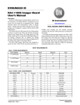
Ver. 4.0 Mar - 2009 APPARATUS CS4 / CSL User’s Manual Supplement to MFK1-FA, MFK1-A User’s Manual Apparatus for measuring temperature variation of magnetic susceptibility AGICO Advanced Geoscience Instruments Co. Brno Czech Republic 2 Contents CONTENTS...........................................................................................................................................................................2 PREFACE............................................................................................................................................................................. 3 CS4 / CSL DESCRIPTION..................................................................................................................................................... 4 CS4 / CSL SPECIFICATIONS..................................................................................................................................................5 INSTALLING AND OPERATING THE CS4 / CSL ...................................................................................................................... 6 High Temperature Furnace ....................................................................................................................................... 6 Temperature Sensor and Specimen............................................................................................................................ 8 Argon Flow Meter......................................................................................................................................................9 Measuring Vessel.....................................................................................................................................................10 Low Temperature Cryostat ..................................................................................................................................... 11 MEASURING HIGH TEMPERATURE VARIATION OF MAGNETIC SUSCEPTIBILITY.............................................................................12 Running the Program............................................................................................................................................... 12 Calibration............................................................................................................................................................... 16 Data File Description............................................................................................................................................... 17 MEASURING LOW TEMPERATURE VARIATION OF MAGNETIC SUSCEPTIBILITY.............................................................................. 20 Running the Program................................................................................................................................................... 20 3 Preface This Supplement is intended for Users who already have Kappabridge MFK1-FA or MFK1-A and extend the instrument by CS4 and/or by CSL Apparatus. ❐ The Part 2 of the User’s Guide MFK1-FA, MFK1-A, Apparatus CS4 / CSL, describes the measurement of temperature variation of magnetic susceptibility using the high temperature furnace CS4 and low temperature cryostat CSL. 4 CS4 / CSL Description The CS4 and CSL (High/Low Temperature Apparatuses) have been designed for measurement in connection with new models Kappabridges MFK1-FA or MFK1-A. The CS4 High Temperature Furnace Apparatus is used for measurement of the temperature variation of low-field magnetic susceptibility of minerals, rocks and synthetic materials in the temperature range from ambient temperature to 700 oC. The apparatus consists of non-magnetic furnace with a special platinum thermometer, CS4 temperature control unit, laboratory power supply EA-PS, cooling water reservoir with pump, and argon flow meter. The specimen is placed in a measuring vessel which is heated by a platinum wire in three selectable heating rates. The temperature is measured by special platinum thermometer. The protective argon atmosphere can be applied during heating to prevent oxidation of measured specimen. In order to perform susceptibility measurement at a chosen temperature range, the equipment moves automatically the furnace into and out of the pick-up coil of the Kappabridge. The quasicontinuous measurement process is fully automated, being controlled by the software. The CSL Low Temperature Cryostat Apparatus is used for measurement of the temperature variation of low-field magnetic susceptibility of minerals, rocks and synthetic materials in the temperature range from minus 192 oC to ambient temperature. The apparatus consists of non-magnetic cryostat with a special platinum thermometer, CS4 temperature control unit and laboratory power supply EA-PS. The specimen is placed in a measuring vessel which is cooled inside the cryostat by liquid nitrogen and then heated spontaneously to a given temperature. The argon gas is needed for deplenishing the liquid nitrogen out of cryostat. Temperature is measured by platinum thermometer. The quasi-continuous measurement process, after cooling the specimen, is fully automated, being controlled by the software. Program CUREVAL serves for off-line data post processing and graphical representation of the data obtained by measurement of temperature variation of magnetic susceptibility of rocks by means of the CS4/CSL High/Low Temperature Apparatus and the Kappabridge. The program for MS-DOS and MS-WIN operating systems is available for free download at company web sites www.agico.com. 5 CS4 / CSL Specifications Maximum specimen volume (fragments or powder) 0.25 cm3 Inner diameter of measuring vessel 6.5 mm Sensitivity to susceptibility changes (976 Hz, 400 Am-1) 1 x 10 -7 SI Temperature range CS4 ambient temperature to 700 oC Temperature range CSL -192 oC to ambient temperature Accuracy of temperature sensor ±2 Argon gas flow requirement (protective atmosphere) approx. 100 ml min-1 Amount of liquid nitrogen (cooling cryostat) approx. 0.25 l for one cooling Power requirements 240, 230, 120, 100 V ±10 %, 50 / 60 Hz Power consumption 350 VA Dimensions / Mass Temperature control unit Laboratory power supply EA-PS Water container with Pump Argon flow meter Furnace/Cryostat 230 mm x 190 mm x 130 mm / 1.7 kg 310 mm x 240 mm x 130 mm / 8 kg 380 mm x 380 mm x 700 mm / 2 kg (without 32 mm x 32 mm x 140 mm / 1 kg diameter 60 mm, length 220 mm / 0.5 kg o C, see also IEC 751 - Pt100 water) 6 Installing and Operating the CS4 / CSL For connection of the CS4/CSL to the Kappabridge MFK1-FA or MFK1-A follow the Interconnection Scheme MFK1-FA/CS4/CSL, (see Chapter Installation Procedures in Manual Part 1, Kapabridge MFK1-FA/CS4/CSL.) High Temperature Furnace The power for heating the furnace is connected through two wire cables fixed by two screws. The heating wire itself is made of platinum bifilar winding. The specimen vessel, the heating tube and the insulation tube are made from silica glass, while the furnace outer tube is made from perspex. The temperature insulation of the furnace consists of a layer of Al2O3 powder and a layer of cooling water. The CS4 apparatus is equipped with a closed water circle for shielding the pick-up coil of the Kappabridge from the hot furnace. The main parts of the cooling system are double mantle of the furnace, pipes, flow indicator and water container with pump. An outlet of “warm” water (WATER-OUT) of the PICK-UP unit left side is connected by approx. 2.5 m long tubing with an inlet IN of the water container. An inlet of “cold” water (WATER-IN) of the PICK-UP unit left side is connected by approx. 2.5 m long tubing with an outlet OUT of the water container. The water reservoir must contain approx. 50 litres of distilled water. It is recommended to add the growth inhibitor of bacteria and fungi, 25 ml for 50 l is sufficient (e.g. BAD STABIL, manufacture NeoLab oder.no.1-6095). Cable from the pump of the water reservoir should be connected to the socket situated on the CS4 Temperature Control Unit. After first filling with water or after any other aerating of the cooling system, it is necessary to carry out its disaeration. It is recommended to do it also after the apparatus has not been in function for a prolonged period of time. 7 The process of the disaeration of the cooling system is as follows : Connect the CS4 apparatus to the MFK1-FA Kappabridge (see Chapter in Manual Part 1, Installation Procedures, Interconnection Scheme, Fig.1), do not forget to connect temperature sensor. Switch on the Kappabridge. Run the program SUFYTE.EXE. After activation of the CS4 FURNACE the program tests the water circle. In case of ## BAD COOLING error message (water flow < 0.3 l/min) persisting more than one minute, check if water pump is connected to the CS4 unit, and if water tubes are not pressed somewhere and if the water tubes are properly connected. The tubes between the furnace and outlet-inlet on upper part of pick-up unit must not be crossed. If the water flow is not sufficient and in the furnace is air it is necessary to deaerate the cooling system. The most easiest way how to deaerate the cooling system is the following. Loose the cap of the water container and raise the cap (with the pump) approximately 30 - 40 cm (the pump should remain immersed in the water) and wait for regeneration of proper water flow. Then immerse the pump to its normal position and fix the cap. Check if the tubes are not twisted. In case the water container is placed for example under the table and picking up the cap of water container is not possible, you can use the another way. Be careful during this operation and cover the pick-up coils to protect them. Press the water input tube (to stop running of water for a while) going from outlet on the upper part of the pick-up coils denoted as “OUT” to the furnace, open water circle by pulling the tube from inlet “IN” on the upper part of pick-up coils, release the pressed water input tube and wait until water without air is running out from the opened tube. Then press the water input tube again, close water circle, release the water input tube and check if the GREEN led COOLING on the Pick-up Unit is ON and if the water flow is at least 0.5 l/min. If necessary you can optionally open the cooling system in the point inlet “IN” on the cap of water container and use the above described procedure similarly. 8 Correct flow of the cooling water is monitored during the operation of the apparatus by control software and by green LED located on the right side of the pick-up unit of MFK1-FA. The LED is on if sufficient amount of water is flowing. Any interruption of the water flow longer than two seconds is signalled by this LED going off, and the heating of the furnace is automatically switched off and the measurement is interrupted. The optimum condition for the measurement is reached when the temperature of water in the container and the temperature in the laboratory are the same. Therefore we recommend to switch on the cooling system approximately 2-3 hours before starting the measurement every time after new tanking or replenishing the container. Normally this is not necessary, because the temperature of water is equal to the ambient temperature. In case the “new” water was stored before filling to the reservoir in another room with different temperature and the measurement was run immediately, the drift of coils during measurement may be increased. Temperature Sensor and Specimen Thermometer is special platinum sensor whose resistance depends on temperature. Thermometer is connected to the system by 15-pin connector, the same as used for the rotator of the MFK1-FA. If you connect the thermometer (or rotator) be sure the Kappabridge is OFF. The sensor and the silica glass pipe are very fragile. For this reason, a very careful manipulation is needed to prevent damaging the pipe when it is inserted in or taken out from measuring tube with specimen. Fill the specimen to the measuring vessel, place it in the horizontal position along the vessel and insert carefully the thermometer. Then set the vessel with thermometer to vertical position and shake gently the specimen down step by step as shown at above pictures. Do not push the thermometer into the specimen which is on the bottom of the measuring vessel. 9 The basic type of a specimen measured is fine powder of a mineral or rock. Small fragments can also be used - in this case add Al2O3 powder to prevent position changes of the fragment(s) during movement up and down. For correct measurement, the specimen should be placed in the area of homogeneous temperature and homogeneous measuring magnetic field. This area extends at the length of 20 mm from the bottom of the specimen vessel. The temperature sensor is placed in the centre of this area. In this case, the measurement of a specimen temperature is the most precise and the measurement of the specimen susceptibility is the most sensitive. Temperature sensor should be carefully cleaned after each specimen measurement. For cleaning use cotton-wool, which can be soaked with various solvents (e.g. acetone, ethanol), if necessary. After cleaning dry up the sensor. Do not use ultrasonic cleaning for thermometer. Take care of outlet wires of the thermometer as well. In any manipulations, do not bend them too much. Argon Flow Meter The protective Argon atmosphere can be optionally used to prevent chemical changes of the specimen during heating. The appropriate flow is about 6 l / hod which corresponds approx. to the one half of argon flow meter scale. 10 Measuring Vessel The specimen silica glass vessel should be cleaned regularly to achieve the right results. Ultrasonic cleaning is a very effective and a very quick procedure for cleaning measuring vessels. Cotton-wool wound on a skewer is used for mechanical cleaning of the specimen vessel interior. Cotton-wool can be soaked with various solvents (e.g. acetone, ethanol). Chemical cleaning is needed if a specimen was smelted during measurement. Contact a chemist for rules for manipulation with acids before using following procedure. Be careful while operating with acids. - put acid in a cylindrical vessel made from laboratory glass - put acid in the specimen vessel - insert the specimen vessel into the acid - let acid act for several hours - exchange acid several times - pour acid out - rinse the specimen vessel with water several times - dry the vessel carefully Some recommended acids: a) HCl b) H2SO4 c) the strongest acid is the chrome-sulphur acid prepared as follows: - use 15g of K2Cr2O7 and 200 ml (cm3) of concentrated H2SO4 - crush finely K2Cr2O7 in a porcelain (or achate) mill - dissolve this powder in concentrate H2SO4 11 Low Temperature Cryostat Cryostat is used for measurement of temperature variation of magnetic susceptibility in temperature range -192 oC to ambient temperature. Before running SUFYTE program which controls the measurement prepare the cryostat to its operating position. Switch off the system. Put the high temperature furnace to its standby position without disconnecting it. Standby position is the place in the black big hole on the pick-up unit. Install the cryostat to the holder and connect the 9-pin connector located on the upper part of the pick-up unit. Check if the cryostat is properly mounted in the notch and if the tube for output the liquid nitrogen is not damaged. 12 Measuring High Temperature Variation of Magnetic Susceptibility The program SUFYTE serves for on-line measurement of temperature variation of magnetic susceptibility, by means of the CS4 Apparatus and MFK1-FA or MFK1-A Kappabridge, in temperature range from ambient temperature to 700 oC. This program requires MS-DOS ver.4.0 and higher, and VGA graphic card. It works also under MS-WIN OS, but in this case all possible savers should be off. Running the Program Check if the temperature sensor is connected and if the cooling system is closed. If you used in the last measuring session SAFYR programme with the option U/D DISABLED (the plastic cylinder may be still present in the coil), remove the plastic cylinder from coil. Switch on the Kappabridge (the power switch EA-PS must be always ON, it is remotely controlled by CS4). Run program SUFYTE.EXE. After the program is started, the communication of the instrument with the computer via the serial channel RS-232 COM1 or COM2 is tested automatically. If the communication is O.K. and initialization of Kappabgidge is successful, the program initializes the CS4 unit and tests the current connected device (furnace or cryostat) and required confirmation or change. If there is no initialization problem, the initial menu appears after entering the file output path, specimen file name and name of empty furnace/cryostat foSr later correction. Select key F1...F6 ( F7 for ver. FA and FB ) F1 MAX. temperature [ 90 to 700 oC ] : 700 F1 MIN. temperature [ 40 to 100 oC ] : 40 F2 y axis min. susceptibility [SI units] :0 F2 y axis max. susceptibility [SI units] 0-auto scale 0-auto scale :0 F3 heating rate [ slow=1 medium=2 fast=3 extra=4 ] : 3 F4 linger at max. temperature [minutes] :0 F5 CONTINUE F6 Field [ 2 to 700 A/m ] F7 Frequency [ 1 to 3 ] : 200 : F1 13 By means of the key F1, one can choose the maximum and minimum temperatures to which the investigated specimen should be heated and cooled, respectively. The pre-set values are those of the last measured specimen (stored in the configuration file SUFYTE.SAV). The values 700 oC and 40 oC are set in the new instrument, because they are probably the most common ones useful in the investigation of the most rocks. They are also the limit values. The maximum temperature cannot be chosen higher than 700 oC (otherwise the message Illegal value appears and the program waits for new input) and the minimum temperature cannot be chosen lower than 40 oC. In addition, the minimum temperature cannot be set higher than 100 oC, because of the necessity of cooling the furnace before measuring the next specimen. Within the above interval, the temperatures can be selected, provided the difference between maximum and minimum temperatures is at least 50 oC. For example, if one investigates pyrrhotite bearing rocks and is interested only in the Curie temperatures of pyrrhotite, one would select the maximum temperature about 350 oC and considerably save measuring time. The key F2 controls the susceptibility scale of the figure of the susceptibility vs. temperature relationship to be drawn on the screen of the computer during measurement. The default values (0,0) mean that the program selects the suitable scale automatically. If one has some preliminary idea of the susceptibility to be measured, one can choose the scale correspondingly. The key F3 controls the heating rate. The default value heat rate 3 corresponds approximately to the rate of 11 oC per minute which is suitable for the most rocks (heating the specimen up to 700 oC and its cooling down to 40 oC takes approximately 2 1/4 hours). For special studies, slower heating rates can be used (1 corresponds approx. 6.5 oC/min or 2 - approx. 8.5 oC/min ), but one must realize that such as measurements take correspondingly longer time. Temperature [C] . 700 600 500 400 300 200 Heat4 ch an ge p o in t 4 8 0 C 100 Heat3 Heat1 0 0 3000 6000 9000 12000 Tim e [s ] If you select value 4 extra, you are asked to enter temperature point of changing the heating rate. This point is calculated by default from Tmax and Tmin temperatures which should be set before setting the temperature point of changing the heating rate. Be sure the point is set properly in case you change Tmax and/or Tmin after setting the temperature point of changing the heating rate. The heat rate is approx. 35 oC/min before point of changing heating rate on heating curve and after point of changing on cooling curve, and approx. 8 oC/min after point of changing on heating curve and before point on cooling curve. It is recommended 14 to set the temperature point at least 50 to 100 oC bellow expected Curie temperature. This option accelerates the measurement in case you are interested in particular Curie temperature. Remark: If you set the temperature point of changing heating rate only 30 oC below max. temperature you can measure all the curve with maximum heating and cooling rate very fast (approx. 40 min. for all curve up to 700 oC). This can be used e.g. for empty furnace measurement or for brief testing purposes. The option heating rate = 4 is not saved in config. file SUFYTE.SAV, it must be set before each measurement exclusively. The key F4 controls the time of the thermal treatment of the specimen at the maximum temperature. The default value 0 means that the temperature, immediately after reaching the maximum temperature set by the F1 key, starts decreasing. If longer heating at the maximum temperature is needed, it must be set using the key F4. However, the thermal treatment at the maximum temperature cannot be set longer than 20 min. The key F6 sets the field. After pressing the key the required Field can be entered. The key F7 sets the frequency. The key F5 is pressed if one agrees with the input data of the entire table. The program also continues after 30 s of no activity. The following menu appears on the screen 1 Menu 2 CStd 3 CAL 4 5 START 6 7 8 9 10 EXIT Key F1 - Return to the initial menu. Key F2 - Calibration Standard nominal value. Key F3 - Calibration procedure. Key F5 - Activates the measurement procedure. Key F10 - Exits the program. Note: The keys F3 and/or F5 are not available in case the nominal value of calibration standard and instrument gain are not saved in configuration file SUFYTE.SAV. After activating the START key F5, the programs starts the measurement of the specimen. Before pressing F5, it is necessary that the powdered specimen is in the measuring vessel, the thermometer is inserted in the specimen and the vessel is inserted in the furnace.During measuring, the screen of the computer has the outlook, whose example is shown. The cooling curve is illustrated on the screen as dashed line. 15 C:\MFK\SUFYTE\xxx.cur Temp: 52.5 oC Heat: 420 mA H= 100 200 A/m F1 Water Flow 0.75 l/min Heat Rate: 3 Tmax:700 Tmin:40 0 [E-6 SI] -20 HAEMAT.CUR -40 -60 -80 -100 -120 Heating -140 Cooling -160 -180 -200 0 100 200 300 400 423: susc Re / Im: -158.9 E-06 / 45 E-09 1 Menu 2 3 4 5 STOP 500 600 700 Water: 0.75 l/min 6 7 8 Linger: 0 min 9 10 The measurement can be aborted any time using STOP Key F5. The STOP have to be confirmed in 10 s, otherwise the measurement continues. The heating is switched off , but the program does not terminate until the temperature is lower than 100 oC . Do not manipulate with measuring tube and with the thermometer until the program terminates ! The message **BULK in the lowermost line alternates during measurement with the message Zeroing in progress.... It informs the operator about current procedure. The message Transferred informs us of how large part of the signal has been transferred from the measuring unit for further evaluation during each Bulk measurement. The message Range informs us of the measuring range set up during auto-ranging to measure the specimen. The leftmost number in the lower line (423 in our example) is the succession number of the measurement of the pair of susceptibility and temperature values. The susc. is the measured total susceptibility value, while Temp is the measured temperature value (in degrees centigrade). The value Heat contains an information of the heating current (in mA units and arbitrary units-steps of step motor controlling auto-transformer). The values Tmax and Tmin are the set up values of the maximum and minimum temperatures, respectively. 16 The values Tmax and Tmin can be changed also during measurement after pressing F1. The measurement is paused for short time, new temperatures are set up and the measurement continues. It should be emphasized that the maximum temperature cannot be selected lower than the actual temperature in the measurement process. The thermomagnetic curve is drawn automatically during the measurement. The computer selects itself the most convenient susceptibility scale, while the temperature scale is always the same, i.e. from 0 to 700 oC. In the case that one wishes to have another susceptibility scale, one can press F1 and adjust the susceptibility scale manually. It should be emphasized here that the measured susceptibilities are the so called total susceptibilities (i.e. those not corrected for the specimen volume or mass). These susceptibilities are stored in the file and displayed on the screen. If one is interested in bulk susceptibilities, one has to enter the data of the specimen volume (or mass and density) or the bulk susceptibility of the measured specimen at the room temperature into the file. This can be made after measurement using the program CUREVAL, which enables the thermomagnetic curves to be presented in various ways (correction for empty furnace, smoothing, etc.) The way of determination of the Curie temperature from measured curve is illustrated on the following figure. It should be noted that this way is not the only one. The inflexion point is also sometimes used as Curie temperature point. In this case its value is a little bit lower. 2500 2000 1500 1000 500 Tc 0 300 320 340 360 380 400 420 440 460 480 Calibration During this procedure follow the instruction on the screen. This calibration is made as for the bulk susceptibility value along the vertical axis of the calibration standard. Before the calibration install the adapter for manual holder. The standard is fixed in the manual holder vertically (in the first measuring position). Perform the calibration after at least 10 minutes of warm-up time. Generally it is recommended to calibrate the bridge every day before beginning the work. However, since the gain changes of the instrument are usually very small and in the case the absolute value of susceptibility is not precisely important (like in temperature variation susceptibility measurement) it is not quite necessary to calibrate the bridge every day. The instrument should be always calibrated when the frequency was changed. The program checks and displays the day of the last calibration and recommends to calibrate in case the last calibration was performed more than 100 days ago. 17 Data File Description The data obtained by measurement are stored in random access ASCII files made automatically during measurement. Each file contains the data of one specimen and has the extension .CUR for high temperature data and .CLW for low temperature data. The first record contains the abbreviations of the parameters stored in individual columns. The second and other records contain the values of the measured and calculated parameters (later by program Cureval) specified in the following table. Abbreviation Length Parameter stored TEMP 9 bytes temperature (in degrees centigrade) TSUSC 9 uncorrected total in-phase susceptibility CSUSC 10 total susc. corrected for empty furnace NSUSC 6 BULKS 12 FERRT 9 total susc. of separated ferromagnetic comp. FERRB 9 bulk susc. of separated ferromagnetic comp. TIME 7 time of measurement (in seconds) (AUXI) 9 auxiliary data susceptibility normalized by maximum value bulk susceptibility The column containing the auxiliary data is not headed AUXI, but by the name of the free furnace for which the measured data are corrected (F20056 in our example shown below). The suceptibilities except the normalized ones are given in the order of 10-6 in unit SI. The file appears as in the following example : TEMP TSUSC CSUSC NSUSC BULKS FERRT 21.2 -164.4 12.94 .650 815.0 2.3 21.5 -164.4 12.74 .640 802.4 2.1 FERRB TIME F20056 147.2 0 815 135.3 16 .170 18 Examples of High Temperature Measurement with CS4 Ktot -165 [E-6 SI] Ktot 800 EMPTY FURNICE Curie Temperatures NIKL + MAGNETITE [E-6 SI] (without correction for furnace) (raw data before smoothing) 600 -170 400 200 -175 0 -180 -200 0 100 200 300 400 500 600 700 800 0 100 200 300 400 500 Temperature [°C] Ktot 100 [E-6 SI] Ktot 100 700 [E-6 SI] Hopkinson Peak - HAEMATITE 80 80 60 60 40 40 20 20 0 600 Temperature [°C] ILMENITE 0 0 100 200 300 400 500 600 Temperature 700 [°C] 0 100 200 300 400 500 600 Temperature 700 [°C] 19 The following examples illustrate that some new fabric can progress and/or decay during the first heating. The repeated measurement of the already once measured specimen may be different form the first one. The interpretation of the curves is thus not quite clear and simple. specimen M1- second measurement specimen M1 - first measurement susc.[SI] susc. [E-3 SI] 0.20 15 heating 0.15 10 heating cooling 0.10 5 0.05 cooling 0 0.00 0 100 200 300 400 500 600 700 0 800 T [C] 100 specimen M7 - first measurement s us c. [SI] 300 400 500 600 700 800 T [C] specimen M7 - second measurement s us c. [SI] 0.3 200 0.3 heating 0.2 0.2 cooling cooling 0.1 0.1 heating 0 0 100 200 300 400 500 600 700 T [C] 0 0 100 200 300 400 500 600 700 T [C] 20 Measuring Low Temperature Variation of Magnetic Susceptibility The program SUFYTE serves for on-line measurement of temperature variation of magnetic susceptibility, by means of the CS4 and CSL Apparatus and Kappabridge MFK1-FA or MFK1-A, in temperature range from -192 oC to ambient temperature. This program requires MS-DOS ver.4.0 and higher, and VGA graphic card. It works also under MS-WIN OS, but in this case all possible savers should be off. The operation of the program SUFYTE for low temperature range is very similar to high temperature measurement, only some parameters which have no sense in low temperature measurement are omitted. Running the Program Install the high temperature furnace to its standby position without connecting it. If you used in the last measuring session SAFYR programme with U/D option disabled (the plastic cylinder may be still present in the coil), remove the plastic cylinder from coil. Install the cryostat to the holder and connect the 9-pin connector located on the upper part of the pick-up unit. Check if the cryostat is properly mounted in the notch, if the tube for output the liquid nitrogen is not damaged. Check also if the temperature sensor is connected. Switch on the Kappabridge (the power switch EA-PS must be always ON, it is remotely controlled by CS4). Run program SUFYTE.EXE. After the program is started, the communication of the instrument with the computer via the serial channel RS-232 COM1 or COM2 is tested automatically. If the communication is O.K. and initialization of Kappabgidge is successful, the program initializes the CS4 unit and tests the current connected device (furnace or cryostat) and required confirmation or change. If there is no initialization problem, the initial menu appears after entering the file output path, specimen file name and name of empty furnace/cryostat for later correction. If everything is O.K., prepare the specimen and insert the measuring tube with the thermometer into the cryostat. The calibration procedure is available only if the temperature in the cryostat is higher than 5 oC. If you wish to calibrate the instrument, perform it at the beginning of daily session. 21 Follow the instruction on the computer screen. Fill liquid nitrogen very slowly and wait for required temperature. Do not fill more nitrogen than the level where the teflon white body is decreasing its diameter. After the minimum temperature is reached the computer beeps - it means “be ready to apply argon gas” to force out the nitrogen out of the cryostat. Wait for the message 'Apply Argon and Start Measurement' - then use argon gas, flow about 20 l/min for approx. 3 sec., wait a few seconds and apply argon once again, two or three times. When the argon is flowing into the cryostat, press the front hole by finger at the same time to increase the pressure of the argon inside the cryostat to achieve easier deplenishing of the cryostat. If there is no liquid nitrogen inside the cryostat start measurement by pressing START Key F5. During measurement you can change the value Tmax. and the scale for susceptibility axis (in SI unit). Examples of Low Temperature Measurement with CSL Ktot -105 [E-6 SI] Ktot 10 [E-6 SI] MORIN TRANSITION IN HAEMATITE -106 8 EMPTY CRYOSTAT (after smoothing) -107 6 antiparallel spins -108 canted spins 4 -109 -110 2 -200 -150 -100 -50 0 -200 -150 -100 -50 Temperature [°C] 0 Temperature [°C] Ktot 10000 [E-6 SI] VERWEY TRANSITION IN MAGNETITE 9000 8000 7000 6000 5000 rhombic structure cubic structure 4000 3000 -200 Last Revision: 02-Mar-09 -150 -100 Temperature [C] -50 0