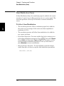
1
Agilent 33500 Series
30 MHz Function /
Arbitrary Waveform
Generator
User’s Guide
Agilent Technologies
Notices
© Agilent Technologies, Inc. 2010
No part of this manual may be reproduced in any form or by any means
(including electronic storage and
retrieval or translation into a foreign
language) without prior agreement and
written consent from Agilent Technologies, Inc. as governed by United States
and international copyright laws.
Manual Part Number
33520-90001
First Edition, June 2010
Second Edition, July 2010
Third Edition, December 2010
Printed in Malaysia
Agilent Technologies, Inc.
900 S. Taft Ave.
Loveland, CO 80537 USA
Adobe, the Adobe Logo, Acrobat and
the Acrobat Logo are trademarks of
Adobe Systems Incorporated.
Microsoft is either a registered trademark or a trademark of Microsoft Corporation in the United States and/or
other countries.
Windows and MS Windows are U.S.
registered trademarks of Microsoft
Corporation.
Software Updates/Licenses
Periodically, Agilent releases software
updates to fix known defects and incorporate product enhancements. To search for
software updates and the latest documentation for your product, go to the product page
at:
www.agilent.com/find/33521A
www.agilent.com/find/33522A
A portion of the software in this product is
licensed under terms of the General Public
License Version 2 ("GPLv2"). The text of
the license and source code can be found at:
www.agilent.com/find/GPLV2
This product utilizes Microsoft Windows
CE. Agilent highly recommends that all
Windows-based computers connected to
Windows CE instruments utilize current
anti-virus software. For more information,
go to the product page at:
www.agilent.com/find/33521A
www.agilent.com/find/33522A
Warranty
The material contained in this
document is provided “as is,” and
is subject to being changed, without notice, in future editions.
Further, to the maximum extent
permitted by applicable law, Agilent disclaims all warranties,
either express or implied, with
regard to this manual and any
information contained herein,
including but not limited to the
implied warranties of merchantability and fitness for a particular purpose. Agilent shall not be
liable for errors or for incidental
or consequential damages in connection with the furnishing, use,
or performance of this document
or of any information contained
herein. Should Agilent and the
user have a separate written
agreement with warranty terms
covering the material in this document that conflict with these
terms, the warranty terms in the
separate agreement shall control.
software” as defined in FAR 52.227-19
(June 1987) or any equivalent agency
regulation or contract clause. Use,
duplication or disclosure of Software is
subject to Agilent Technologies’ standard commercial license terms, and
non-DOD Departments and Agencies
of the U.S. Government will receive no
greater than Restricted Rights as
defined in FAR 52.227-19(c)(1-2)
(June 1987). U.S. Government users
will receive no greater than Limited
Rights as defined in FAR 52.227-14
(June 1987) or DFAR 252.227-7015
(b)(2) (November 1995), as applicable
in any technical data.
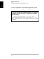
Safety Notices
A CAUTION notice denotes a hazard.
It calls attention to an operating procedure, practice, or the like that, if not
correctly performed or adhered to,
could result in damage to the product or
loss of important data. Do not proceed
beyond a CAUTION notice until the
indicated conditions are fully understood and met.
Technology Licenses
The hardware and/or software
described in this document are furnished under a license and may be used
or copied only in accordance with the
terms of such license.
Restricted Rights Legend
If software is for use in the performance of a U.S. Government prime
contract or subcontract, Software is
delivered and licensed as “Commercial
computer software” as defined in
DFAR 252.227-7014 (June 1995), or as
a “commercial item” as defined in FAR
2.101(a) or as “Restricted computer
A WARNING notice denotes a hazard. It calls attention to an operating
procedure, practice, or the like that,
if not correctly performed or
adhered to, could result in personal
injury or death. Do not proceed
beyond a WARNING notice until the
indicated conditions are fully understood and met.
Additional Safety Notices
The following general safety precautions must be observed during all
phases of operation of this instrument.
Failure to comply with these precautions or with specific warnings or
instructions elsewhere in this manual
violates safety standards of design,
manufacture, and intended use of the
instrument. Agilent Technologies
assumes no liability of the customer’s
failure to comply with the requirements.
Do Not Remove the
Instrument Cover
Only qualified, service-trained personal
who are aware of the hazards involved
should remove instrument covers.
Always disconnect the power cable and
any external circuits before removing
the instrument cover.
Technical Support
If you have questions about your
shipment, or if you need
information about warranty,
service, or technical support,
contact Agilent Technologies:
In the United States: (800) 8294444
Do Not Modify the
Instrument
In Europe: 31 20 547 2111
Or go to
Do not use this product in any manner
not specified by the manufacturer. The
protective features of this product may
be impaired if it is used in a manner not
specified in the operation instructions.
Do not install substitute parts or perform any unauthorized modification to
the product. Return the product to an
Agilent Sales and Service Office for
service and repair to ensure that safety
features are maintained.
Before Applying Power
In Case of Damage
Verify that all safety precautions are
taken. Make all connections to the unit
before applying power and select the
appropriate power line voltage on the
fuse module.
Instruments that appear damaged or
defective should be made inoperative
and secured against unintended operation until they can be repaired by qualified service personnel.
General
Ground the Instrument
This product is provided with protective earth terminals. To minimize shock
hazard, the instrument must be connected to the ac power mains through a
grounded power cable, with the ground
wire firmly connected to an electrical
ground (safety ground) at the power
outlet. Any interruption of the protective (grounding) conductor or disconnection of the protective earth terminal
will cause a potential shock hazard that
could result in personal injury.
Do Not Operate in an
Explosive Atmosphere
Do not operate the instrument in the
presence of flammable gases or fumes.
Unless otherwise noted in the specifications, this instrument or system is
intended for indoor use in an installation category II, pollution degree 2
environment per IEC 61010-1 and 664
respectively. It is designed to operate at
a maximum relative humidity of 20%
to 80% at 40 °C or less (non-condensing). This instrument or system is
designed to operate at altitudes up to
2000 meters, and at temperatures
between 0 °C and 55 °C.
In Japan: 0120-421-345
www.agilent.com/find/assist
for information on contacting
Agilent in your country of specific
location. You can also contact your
Agilent Technologies
Representative.
Safety Symbols
Alternating current
Frame or chassis
terminal
Standby supply. Unit is not
completely disconnected
from AC mains when
switch is off.
Caution, risk of electric
shock
Caution, refer to
accompanying documents
Earth ground terminal
The CE mark is a
registered trademark of the
European Community.
The CSA mark is a
registered trademark of the
CSA-International.
The C-tick mark is a
registered trademark of the
Spectrum Management
Agency of Australia. This
signifies compliance with the
Australian EMC Framework
regulations under the terms of
the Radio Communications
Act of 1992.
Contains one or more of
the 6 hazardous substances
above the maximum
concentration value
(MCV), 40 Year EPUP.
This text indicates that the
instrument is an Industrial
1SM1-A Scientific and Medical
Group 1 Class A product
(CISPER 11, Clause 4).
ICES/
NMB
-001
This text indicates product
compliance with the
Canadian InterferenceCausing Equipment
Standard (ICES-001).
User’s Guide
Publication Number 33520-90001 (order as 33520-90000 manual set)
Edition 3, December 2010
Copyright © 2010 Agilent Technologies, Inc.
Agilent 33500 Series
30 MHz Function /
Arbitrary Waveform Generator
Agilent 33500 Series at a Glance
The Agilent Technologies 33500 Series is a 30 MHz synthesized
waveform generator with built-in arbitrary waveform and pulse
capabilities. Its combination of bench-top and system features makes
this waveform generator a versatile solution for your testing
requirements now and in the future.
Convenient bench-top features
• 16 standard waveforms
• Built-in 16-bit 250 MSa/s arbitrary waveform capability
• Precise pulse waveform capabilities with adjustable edge time
• LCD display provides numeric and graphical views
• Easy-to-use knob and numeric keypad
• Instrument state storage with user-defined names
• Portable, ruggedized case with non-skid feet
Flexible system features
• Downloadable 1M-point or optional 16M-point arbitrary waveform
memories. For details, see:
www.agilent.com/find/33521U
www.agilent.com/find/33522U
• Optional GPIB (IEEE-488)
• Standard USB and LAN remote interfaces
• LXI Class C Compliant
• SCPI (Standard Commands for Programmable Instruments) compatibility
Note: Unless otherwise indicated, this manual applies to all Serial Numbers.
6
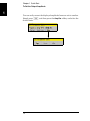
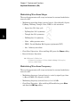
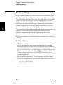
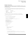
The Front Panel at a Glance
4
3
7
1
5
8
{
2
10
{
{
9
11
12
13
15
16
14
6
1 USB Port
2 On/Off Switch
3 Channel 1 Summary Tab
4 Channel 2 Summary Tab
5 Waveform and Parameter Display Area
6 Menu Operation Softkeys
7 Waveforms/Parameters/Units Keys
8 Modulate/Sweep/Burst Keys
9 System Key
10 Numeric Keypad
11 Knob
12 Cursor Keys (Arrows)
13 Manual Trigger (Sweep and Burst only)
14 Sync Connector
15 Channel 1
16 Channel 2 (2-channel instrument only)
Note: To get context-sensitive help on any front-panel key or menu softkey,
press and hold down that key.
7
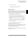
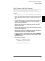
The Front-Panel Display at a Glance
Channel 1
Information
Channel 2
Information
Waveform
Display
Waveform
Parameters
Sweep or Burst
Parameters
Softkey Labels
8
Front-Panel Number Entry
You can enter numbers from the front-panel using one of two methods.
Use the knob and cursor keys to modify the displayed number.
1. Use the keys below the knob to move the cursor left or right.
2. Rotate the knob to change a digit (clockwise to increase).
Use the keypad to enter numbers and the softkeys to select units.
1. Key in a value using the keypad.
2. Select a unit to enter the value.
3. Use the +/- key to change the sign of the number.
4. The left arrow backspaces and clears the last digit.
9
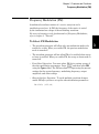
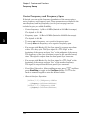
The Rear Panel at a Glance
1
4
3
2
9
10
5
6
7
8
1 External 10 MHz Reference Input Terminal
2 Internal 10 MHz Reference Output Terminal
3 GPIB Interface Connector (option 400)
4 Chassis Ground
5 External Modulation Input Terminal
6 Input: External Trig/Gate/FSK/Burst
7 USB Interface Connector
8 Local Area Network (LAN) Connector
9 Instrument Cable Lock
10 AC Power
WARNING
For protection from electrical shock, the power cord ground must not be
defeated. If only a two-contact electrical outlet is available, connect the
instrument’s chassis ground screw (see above) to a good earth ground.
10
In This Book
Quick Start Chapter 1 prepares the waveform generator for use and
helps you get familiar with a few of its front-panel features.
Front-Panel Menu Operation Chapter 2 introduces you to the frontpanel menu and describes some of the waveform generator’s menu
features.
Features and Functions Chapter 3 gives a detailed description of the
waveform generator’s capabilities and operation. You will find this
chapter useful whether you are operating the waveform generator from
the front panel or over the remote interface.
Application Programs Chapter 4 contains several remote interface
application programs to help you develop programs for your application.
Tutorial Chapter 5 discusses the fundamentals of signal generation
and modulation techniques.
Specifications Chapter 6 lists the waveform generator’s specifications.
You can contact Agilent Technologies at one of the following telephone
numbers for warranty, service, or technical support information.
In the United States: (800) 829-4444
In Europe:
In Japan:
31 20 547 2111
0120-421-345
Or use our Web link for information on contacting Agilent worldwide.
www.agilent.com/find/assist
Or contact your Agilent Technologies Representative.
11
12
Agilent 33500 Series at a Glance 6
The Front Panel at a Glance 7
The Front-Panel Display at a Glance 8
Front-Panel Number Entry 9
The Rear Panel at a Glance 10
In This Book 11
Quick Start 4
To Prepare the Waveform Generator for Use 5
To Adjust the Carrying Handle 7
To Set the Output Frequency 8
To Set the Output Amplitude 10
To Set a DC Offset Voltage 13
To Set the High-Level and Low-Level Values 15
To Output a DC Voltage 17
To Set the Duty Cycle of a Square Wave 18
To Configure a Pulse Waveform 20
To Select a Stored Arbitrary Waveform 22
To Use the Built-In Help System 23
To Rack Mount the Waveform Generator 26
Front-Panel Menu Operation 30
Front-Panel Menu Reference 31
To Select the Output Termination 35
To Reset the Waveform Generator 36
To Output a Modulated Waveform 37
To Output an FSK Waveform 39
To Output a PWM Waveform 41
To Output a Frequency Sweep 44
To Output a Burst Waveform 47
To Trigger a Sweep or Burst 50
To Store the Instrument State 51
To Configure the Remote Interface 53
To Set up an Arbitrary Waveform 61
Features and Functions 78
Output Configuration 80
Pulse Waveforms 98
Amplitude Modulation (AM) 102
Frequency Modulation (FM) 107
Phase Modulation (PM) 113
Frequency-Shift Keying (FSK) Modulation 119
Pulse Width Modulation (PWM) 123
Sum Modulation (Sum) 128
Frequency Sweep 132
Burst Mode 141
Triggering 150
Dual Channel Operations (33522A Only) 156
System-Related Operations 163
Remote Interface Configuration 174
External Timebase Reference 183
Calibration Overview 186
Embedded Waveform Editor 190
Factory Default Settings 211
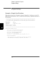
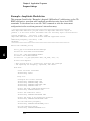
Application Programs 214
Introduction 214
Program Listings 216
Tutorial 240
1
1
Quick Start
Quick Start
1
One of the first things you will want to do with your waveform generator
is to become acquainted with the front panel. We have written the
exercises in this chapter to prepare the instrument for use and help you
get familiar with some of its front-panel operations. This chapter is
divided into the following sections:
• To Prepare the Waveform Generator for Use, on page 5
• To Adjust the Carrying Handle, on page 7
• To Set the Output Frequency, on page 8
• To Set the Output Amplitude, on page 10
• To Set a DC Offset Voltage, on page 13
• To Set the High-Level and Low-Level Values, on page 15
• To Output a DC Voltage, on page 17
• To Set the Duty Cycle of a Square Wave, on page 18
• To Configure a Pulse Waveform, on page 20
• To Select a Stored Arbitrary Waveform, on page 22
• To Use the Built-In Help System, on page 23
• To Rack Mount the Waveform Generator, on page 26
4
Chapter 1 Quick Start
To Prepare the Waveform Generator for Use
1
To Prepare the Waveform Generator for Use
1 Check the list of supplied items.
Verify that you have received the following items with your instrument.
If anything is missing, please contact your nearest Agilent Sales Office.
• Power cord (for country of destination).
4
• Certificate of Calibration.
• Agilent 33500 Series Product Reference CD (product software,
programming examples, and manuals).
• Agilent Automation-Ready CD (Agilent IO Libraries Suite).
• USB 2.0 cable.
Note: All of the 33500 Series product documentation is provided on the
Agilent 33500 Series Product Reference CD that comes with the product,
and is also available on the Web at www.agilent.com/find/33521A and
www.agilent.com/find/33522A. Printed (hardcopy) manuals are
available as an extra cost option.
Power
Switch
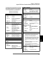
2 Connect the power cord and turn on the waveform generator.
The instrument runs a power-on self test. When the instrument is ready
for use it displays a message about how to obtain help, along with the
current IP address. The instrument also displays the GPIB address if the
GPIB option is installed and GPIB is enabled. The waveform generator
powers up in the sine wave function at 1 kHz with an amplitude of 100
mV peak-to-peak (into a 50 termination). At power-on, the channel
output connectors are disabled. To enable output on a channel connector,
press the
(33521A)
or
(33522A) button and then
press the Output Off / On softkey.
If the waveform generator does not turn on, verify that the power cord is
firmly connected to the power receptacle on the rear panel (the power-line
voltage is automatically sensed at power-on). You should also make sure
that the waveform generator is connected to an energized power source.
Then, verify that the waveform generator is turned on.
Also look at the LED below the power switch. If it is off, there is no AC
power connected. If it is amber, the instrument is in standby mode with
AC power connected, and if it is green, the instrument is on.
5
Chapter 1 Quick Start
To Prepare the Waveform Generator for Use
1
To turn off the instrument, you must hold the power switch down for
about 500 ms. This prevents you from accidentally turning off the
instrument by brushing against the power switch.
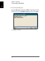
If the power-on self test fails, the instrument shows the ERR annunciator
in the upper right corner of the display. It also prominently displays the
following message:
Check for error messages in the error queue.
See the Agilent 33500 Series Service Guide for information on error
codes, and for instructions on returning the waveform generator to Agilent
for service.
6
Chapter 1 Quick Start
To Adjust the Carrying Handle
1
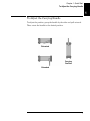
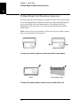
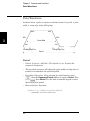
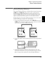
To Adjust the Carrying Handle
To adjust the position, grasp the handle by the sides and pull outward.
Then, rotate the handle to the desired position.
4
Retracted
Carrying
Position
Extended
7
Chapter 1 Quick Start
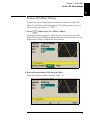
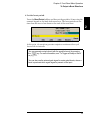
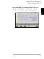
To Set the Output Frequency
1
To Set the Output Frequency
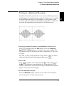
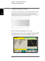
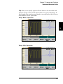
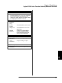
At power-on, the waveform is configured for a sine wave at 1 kHz with an
amplitude of 100 mV peak-to-peak (into a 50 termination).
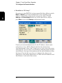
The following steps show you how to change the frequency to 1.2 MHz.
1 Press the
button, followed by the Frequency softkey.
The displayed frequency is either the power-on value or the frequency
previously selected. When you change functions, the same frequency is
used if the present value is valid for the new function. To set the
waveform period instead, press
, then press the Frequency softkey
to toggle to the Period softkey (the current Frequency selection is
highlighted in the image below.).
2 Enter the magnitude of the desired frequency.
Using the numeric keypad, enter the value 1.2.
8
Chapter 1 Quick Start
To Set the Output Frequency
1
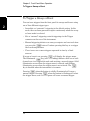
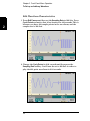
3 Select the desired units.
Press the softkey that corresponds to the desired units. When you select
the units, the waveform generator outputs a waveform with the
displayed frequency (if the output is enabled). For this example,
press MHz.
Note: You can also enter the desired value using the knob and cursor
keys.
4
9
Chapter 1 Quick Start
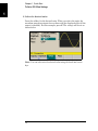
To Set the Output Amplitude
1
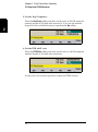
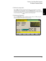
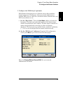
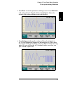
To Set the Output Amplitude
At power-on, the waveform generator is configured for a sine wave with
an amplitude of 100 mV peak-to-peak (into a 50 termination).
The following steps show you how to change the amplitude to 50 mVpp.
, then the softkey marked Amp/Offs or High/Low to
1 Press
make sure that you are in Amp/Offs.
The displayed amplitude is either the power-on value or the amplitude
previously selected. When you change functions, the same amplitude is
used if the present value is valid for the new function. To choose whether
you want to specify voltage as amplitude and offset or high and low values,
press
and then the second softkey. In this case, we will highlight
Amp/Offs.
10
Chapter 1 Quick Start
To Set the Output Amplitude
1
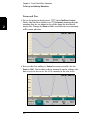
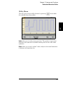
2 Enter the magnitude of the desired amplitude.
Press
and then press Amplitude. Using the numeric keypad,
enter the number 50.
4
3 Select the desired units.
Press the softkey that corresponds to the desired units. When you select
the units, the waveform generator outputs the waveform with the
displayed amplitude (if the output is enabled). For this example, press
mVpp.
Note: You can also enter the desired value using the knob and cursor
keys. If you do so, you do not need to use a units softkey.
11
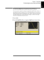
Chapter 1 Quick Start
To Set the Output Amplitude
1
You can easily convert the displayed amplitude from one unit to another.
Simply press
, and then press the Ampl As softkey and select the
desired units.
12
Chapter 1 Quick Start
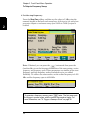
To Set a DC Offset Voltage
1
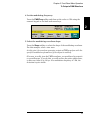
To Set a DC Offset Voltage
At power-on, the waveform generator outputs a sine wave with a DC
offset of 0 volts (into a 50 termination). The following steps show you
how to change the offset to –1.5 VDC.
1 Press
, followed by the “Offset” softkey.
4
The displayed offset voltage is either the power-on value or the offset
previously selected. When you change functions, the same offset is used
if the present value is valid for the new function.
2 Enter the magnitude of the desired offset.
Using the numeric keypad, enter the value “–1.5”.
13
Chapter 1 Quick Start
To Set a DC Offset Voltage
1
3 Select the desired units.
Press the softkey for the desired units. When you select the units, the
waveform generator outputs the waveform with the displayed offset (if the
output is enabled). For this example, press V. The voltage will be set as
shown below.
Note: You can also enter the desired value using the knob and cursor
keys.
14
Chapter 1 Quick Start
To Set the High-Level and Low-Level Values
1
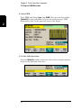
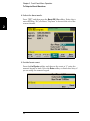
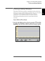
To Set the High-Level and Low-Level Values
You can specify a signal by setting its amplitude and DC offset values, as
described previously. Another way to set the signal limits is to specify its
high (maximum) and low (minimum) values. This is typically convenient
for digital applications. In the following example, we will set the high
level to 1.0 V and the low level to 0.0 V.
4
1 Press
.
2 Press the Amp/Offs softkey to toggle to High/Low as shown below.
15
Chapter 1 Quick Start
To Set the High-Level and Low-Level Values
1
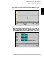
3 Set the “High Level” value.
Press the
key and select High Level. Using the numeric keypad or
knob and arrows, select a value of 1.0 V. (If you are using the keypad,
you will need to select the V unit softkey to enter the value.)
4 Press the Low Level softkey and set the value.
Again, use the numeric keypad or the knob to enter a value of 0.0 V.
These settings (high-level = 1.0 V and low-level = 0.0 V) are equivalent to
setting an amplitude of 1.0 Vpp and an offset of 500 mV.
16
Chapter 1 Quick Start
To Output a DC Voltage
1
To Output a DC Voltage
You can specify a constant DC voltage to be output
1 Press
and then select More and DC.
The Offset value becomes selected.
4
2 Enter the desired voltage level as an Offset.
Enter 1.0 with the numeric keypad or knob and then press the V softkey
if you used the keypad.
You can enter any DC voltage from -5 V to +5 V into 50 , or -10 V to
+10 V into a high impedance load.
17
Chapter 1 Quick Start
To Set the Duty Cycle of a Square Wave
1
To Set the Duty Cycle of a Square Wave
At power-on, the duty cycle for square waves is 50%. The duty cycle is
limited by the minimum pulse width specification of 16 ns. The following
steps show you how to change the duty cycle to 75%.
1 Select the square wave function.
Press the
key and choose Square.
2 Press the Duty Cycle softkey.
The displayed duty cycle is either the power-on value or the percentage
previously selected. The duty cycle represents the amount of time per
cycle that the square wave is at a high level.
18
Chapter 1 Quick Start
To Set the Duty Cycle of a Square Wave
1
3 Enter the desired duty cycle.
Using the numeric keypad or the knob and arrows, select a duty cycle
value of “75”. If you are using the numeric keypad, press the Percent
softkey to finish the entry. The waveform generator adjusts the duty
cycle immediately and outputs a square wave with the specified value (if
the output is enabled).
4
19
Chapter 1 Quick Start
To Configure a Pulse Waveform
1
To Configure a Pulse Waveform
You can configure the waveform generator to output a pulse waveform
with variable pulse width and edge time. The following steps show you
how to configure a 500 ms periodic pulse waveform with a pulse width of
10 ms and edge times of 50 ns.
1 Select the pulse function.
Press the
key and choose Pulse to select the pulse function and
output a pulse waveform with the default parameters.
2 Set the pulse period.
Press the
key and then press the Frequency/Period softkey to
choose Period. Then press
and choose Period. Set the period to
500 ms.
20
Chapter 1 Quick Start
To Configure a Pulse Waveform
1
3 Set the pulse width.
Press
and the Pulse Width softkey, and then set the pulse width
to 10 ms. The pulse width represents the time from the 50% threshold of
the rising edge to the 50% threshold of the next falling edge.
4
4 Set the edge time for both edges.
Press the Edge Time softkey and then set the edge time for both the
leading and trailing edges to 50 ns. The edge time represents the time
from the 10% threshold to the 90% threshold of each edge.
21
Chapter 1 Quick Start
To Select a Stored Arbitrary Waveform
1
To Select a Stored Arbitrary Waveform
There are nine built-in arbitrary waveforms stored in non-volatile
memory. They are Cardiac, D-Lorentz, Exponential Fall, Exponential
Rise, Gaussian, Haversine, Lorentz, Negative Ramp, and Sinc.
The following steps show you how to select the built-in “exponential fall”
waveform from the front panel.
For information on creating a custom arbitrary waveform, refer to
“To Set up an Arbitrary Waveform” on page 61.
1 Select the arbitrary waveform function.
Press the
button and choose the Arb softkey and then the Arbs
softkey. Then choose Select Arb and use the knob to select Exp_Fall.
Press Select.
22
Chapter 1 Quick Start
To Use the Built-In Help System
1
To Use the Built-In Help System
The built-in help system is designed to provide context-sensitive
assistance on any front-panel key or menu softkey. A list of help topics
is also available to assist you with several front-panel operations.
1 View the help information for a function key.
4
Press and hold down any softkey or button such as
. If the message
contains more information than will fit on the display, press thesoftkey
or use the knob to view the remaining information.
Press Done to exit Help.
23
Chapter 1 Quick Start
To Use the Built-In Help System
1
2 View the list of help topics.
Press the
button and then press Help to view the list of available
help topics. To scroll through the list, press the andsoftkeys or use
the knob. Select the topic Get HELP on any key and then press Select.
Press Done to exit Help.
24
Chapter 1 Quick Start
To Use the Built-In Help System
1
3 View the help information for displayed messages.
Whenever a limit is exceeded or any other invalid configuration is found,
the waveform generator will display a message. The built-in help system
provides additional information on the most recent message.
Press the
button and then press Help. Then select the topic View
the last message displayed, and press Select.
4
Press Done to exit Help.
Local Language Help: The built-in help system is available in Chinese,
French, German, Japanese, and Korean. All messages, contextsensitive help, and help topics appear in the selected language. The
menu softkey labels and status line messages are not translated.
To select the local language, press the
button, then press the
System Setup softkey, the User Settings softkey, and the Help Lang
softkey. Then select the desired language.
25
Chapter 1 Quick Start
To Rack Mount the Waveform Generator
1
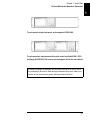
To Rack Mount the Waveform Generator
You can mount the instrument in a standard 19-inch rack cabinet using
one of two optional kits available. Instructions and mounting hardware
are included with each rack-mounting kit. Any Agilent System II
instrument of the same size can be rack-mounted beside the Agilent
33500 Series.
Note: Remove the carrying handle, and the front and rear rubber bumpers,
before rack-mounting the instrument.
To remove the handle, rotate it to vertical and pull the ends outward.
Front
Rear (bottom view)
To remove the rubber bumper, stretch a corner and then slide it off.
26
Chapter 1 Quick Start
To Rack Mount the Waveform Generator
1
To rack mount a single instrument, order adapter kit 5063-9240.
4
To rack mount two instruments side-by-side, order lock-link kit 5061- 8769
and flange kit 5063-9212. Be sure to use the support rails in the rack cabinet.
In order to prevent overheating, do not block the flow of air into or out of
the instrument. Be sure to allow enough clearance at the rear, sides, and
bottom of the instrument to permit adequate internal air flow.
27
Chapter 1 Quick Start
To Rack Mount the Waveform Generator
1
28
2
2
Front-Panel Menu Operation
Front-Panel Menu Operation
This chapter introduces you to the front-panel keys and menu operation.
This chapter does not give a detailed description of every front-panel key
or menu operation. It does, however, give you an overview of the frontpanel menus and many front-panel operations. See chapter 3 “Features
and Functions,” starting on page 77, for a complete discussion of the
waveform generator’s capabilities and operation.
2
• Front-Panel Menu Reference, on page 31
• To Select the Output Termination, on page 35
• To Reset the Waveform Generator, on page 36
• To Output a Modulated Waveform, on page 37
• To Output an FSK Waveform, on page 39
• To Output a PWM Waveform, on page 41
• To Output a Frequency Sweep, on page 44
• To Output a Burst Waveform, on page 47
• To Trigger a Sweep or Burst, on page 50
• To Store the Instrument State, on page 51
• To Configure the Remote Interface, on page 53
• To Set up an Arbitrary Waveform, on page 61
30
Chapter 2 Front-Panel Menu Operation
Front-Panel Menu Reference
Front-Panel Menu Reference
This section gives an overview of the front-panel menus. The remainder
of this chapter contains examples of using the front-panel menus.
Select a waveform
4
• Select one of nine waveform types, including Sine, Square, Ramp, Pulse,
Arbitrary, Triangle, Noise, PRBS, and DC.
Configure parameters for the selected waveform
Depending on the waveform, you can do some of the various tasks:
• Configure Period/Frequency
• Configure Amplitude or High and Low Voltage
• Configure Offset
• Configure Phase
• Configure Duty Cycle
• Configure Symmetry
• Configure Pulse Width
• Configure Edge Times
• Configure Arbitrary Waveforms
• Configure Bandwidth
• Configure PRBS Data
• Configure Bit Rate
Specify what units and parameters to use for various waveforms.
•
•
•
•
•
Specify whether to use Frequency or Period
Specify whether to use Amplitude and Offset or High and Low Voltage
Specify which voltage units to use
Specify whether to use Pulse Width or Duty Cycle
Specify whether to configure Frequency sweep as Center/Span or Start/Stop
31
2
Chapter 2 Front-Panel Menu Operation
Front-Panel Menu Reference
Configure the parameters for modulation.
2
•
•
•
•
Turn modulation on or off.
Specify the modulation type.
Specify the modulation source.
Specify parameters for AM, FM, PM, PWM, BPSK, FSK and Sum modulation.
Configure the parameters for frequency sweep.
•
•
•
•
•
•
Turn sweep on or off.
Select linear, logarithmic or frequency list sweeping.
View and edit a list of frequencies to sweep.
Select the time in seconds required to complete a sweep.
Select the start/stop frequencies or center/span frequencies.
Specify dwell, hold, and return times.
Configure the parameters for burst.
•
•
•
•
•
•
Turn burst on or off.
Select the triggered (N Cycle) or externally-gated burst mode.
Select the number of cycles per burst (1 to 100,000,000 or infinite).
Select the starting phase angle of the burst (-360° to +360°).
Specify the number of cycles.
Specify the burst period.
Store/Recall - Store and recall instrument states.
•
•
•
•
•
•
Store an arbitrary number of instrument states in non-volatile memory.
Assign a custom name to each storage location.
Recall stored instrument states.
Delete stored instrument states.
Restore all instrument settings to their factory default values.
Select the instrument’s power-on configuration (last or factory default).
32
Chapter 2 Front-Panel Menu Operation
Front-Panel Menu Reference
I/O Config - Configure instrument I/O interfaces.
•
•
•
•
•
Turn the LAN on and off.
Specify the LAN configuration (IP address and network configuration).
Reset the LAN.
Specify the USB settings.
Select the GPIB address.
2
4
Calibrate - Perform calibration tasks.
• Set the calibration password.
• Lock and unlock the instrument for calibration.
• Calibrate the instrument (see Agilent 33500 Series Service Guide).
Instr Setup - Configure instrument parameters.
• Perform self-test.
• Configure reference oscillator.
• Clear instrument memory (NISPOM secure).
System Setup - Configure system-related parameters.
•
•
•
•
•
•
•
•
•
•
•
Set screen layout.
Select the local language for front-panel messages and help text.
Select how periods and commas are used in numbers displayed on the front panel.
Turn the display on and off.
Enable/disable the beeper heard when an error is generated.
Enable/disable the display screen saver mode.
Adjust the brightness setting of the front-panel display.
Install licenses for licensed features.
Set date and time.
Perform file and folder management (copy, rename, delete, and so on).
Capture screen shots.
33
Chapter 2 Front-Panel Menu Operation
Front-Panel Menu Reference
Help - View the list of Help topics.
2
•
•
•
•
•
View the last message displayed.
View the remote command error queue.
Get help on any key.
Learn how to obtain Agilent Technical Support.
View “about” data - serial number, IP address, firmware version, and so on.
or
•
•
•
•
•
•
•
•
or
Channels - Enable and configure channels.
Turn channel on and off.
Specify which channel is the focus of the menus.
Select the output termination (1 to 10 k, or Infinite).
Enable/disable amplitude autoranging.
Select the waveform polarity (normal or inverted).
Specify voltage limits on channel.
Specify whether the channel is to be in normal or gated mode.
Configure the channel for dual channel operation (33522A).
Configure Trigger Settings
•
•
•
•
•
•
Perform a manual trigger, when illuminated.
Specify the trigger source for the sweep, burst or arbitrary waveform advance.
Specify the trigger count and delay.
Specify the slope (rising or falling edge) for an external trigger source.
Specify the slope (rising or falling edge) of the “Trig Out” signal.
Enable/disable the Sync signal which is output from the “Sync” connector.
34
Chapter 2 Front-Panel Menu Operation
To Select the Output Termination
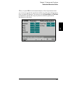
To Select the Output Termination
The Agilent 33500 Series has a fixed series output impedance of 50 to
the front-panel channel connectors. If the actual load impedance is
different than the value specified, the displayed amplitude and offset
levels will be incorrect. The load impedance setting is simply provided
as a convenience to ensure that the displayed voltage matches the
4
expected load.
1 Press
or
or
to open the channel configuration
screen. Note that the current output termination values (both
50 in this case) appear on the tabs at the top of the screen.
2 Specify the output termination.
Press the Output Load softkey.
3 Select the desired output termination.
Use the knob or numeric keypad to select the desired load impedance or
press the Set to 50 softkey or the Set to High Z softkey.
35
2
Chapter 2 Front-Panel Menu Operation
To Reset the Waveform Generator
To Reset the Waveform Generator
2
To reset the instrument to its factory default state, press
select the Store/Recall and Set to Defaults softkeys.
and then
For a complete listing of the instrument’s power-on and reset conditions,
see “Agilent 33500 Series Factory Default Settings” on page 212.
36
Chapter 2 Front-Panel Menu Operation
To Output a Modulated Waveform
To Output a Modulated Waveform
A modulated waveform consists of a carrier and a modulating waveform.
In AM (amplitude modulation), the amplitude of the carrier is varied by
the modulating waveform. For this example, you will output an AM
waveform with 80% modulation depth. The carrier will be a 5 kHz sine
wave and the modulating waveform will be a 200 Hz sine wave.
4
1 Select the function, frequency, and amplitude of the carrier.
Press
and then press the Sine softkey. Press the Frequency,
Amplitude, and Offset softkeys to configure the carrier waveform. For
this example, select a 5 kHz sine wave with an amplitude of 5 Vpp, with
0 V offset.
Note that you may specify amplitude in Vpp, Vrms or dBm. To do this,
either enter the value with the number pad or press
.
2 Select AM.
Press
and then select “AM” using the Type softkey. Then press
the Modulate softkey to turn modulation On. Notice that the
button is illuminated, and the status message “AM Modulated by Sine”
appears at the top left of the display.
3 Set the modulation depth.
Press the AM Depth softkey and then set the value to 80% using the
numeric keypad or the knob and cursor keys.
37
2
Chapter 2 Front-Panel Menu Operation
To Output a Modulated Waveform
4 Select the modulating waveform shape.
Press the Shape softkey to select the shape of the modulating waveform.
For this example, select a sine wave.
2
5 Set the modulating frequency.
Press More and then the AM Freq softkey. Set the value to 200 Hz using
the numeric keypad or the knob and cursor keys. Press the Hz softkey to
finish entering the number if you are using the numeric keypad.
38
Chapter 2 Front-Panel Menu Operation
To Output an FSK Waveform
To Output an FSK Waveform
You can configure the waveform generator to “shift” its output frequency
between two preset values using FSK modulation. The rate at which the
shift happens is the FSK rate, and this FSK rate is determined by the
internal rate generator or the signal level on the rear-panel Ext Trig
connector. The two frequencies that the signal shifts between are called
4
the “carrier frequency” and the “hop frequency.” For this example,
you will set the “carrier” frequency to 3 kHz and the “hop” frequency to
500 Hz, with an FSK rate of 100 Hz.
1 Select the function, frequency, and amplitude of the carrier.
Press
and then press the Sine softkey. Press the Frequency,
Amplitude, and Offset softkeys to configure the carrier waveform. For
this example, select a 3 kHz sine wave with an amplitude of 5 Vpp, with 0
offset.
2 Select FSK.
Press
and then select FSK using the Type softkey. Then press the
Modulate softkey to turn modulation On. Notice the status message
“FSK Modulated” at the top left of the display.
39
2
Chapter 2 Front-Panel Menu Operation
To Output an FSK Waveform
3 Set the “hop” frequency.
Press the Hop Freq softkey and then set the value to 500 Hz using the
numeric keypad or the knob and cursor keys. If you use the numeric
keypad, be sure to finish the entry by pressing the Hz softkey.
2
4 Set the FSK “shift” rate.
Press the FSK Rate softkey and then set the value to 100 Hz using the
numeric keypad or the knob and cursor keys.
At this point, the waveform generator outputs an FSK waveform.
40
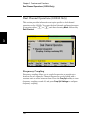
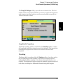
Chapter 2 Front-Panel Menu Operation
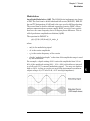
To Output a PWM Waveform
To Output a PWM Waveform
You can configure the waveform generator to output a pulse width
modulated (PWM) waveform. The Agilent 33500 Series provides PWM
for pulse carrier waveforms. In PWM, the pulse width or duty cycle of the
carrier waveform is varied according to the modulating waveform. You
can specify either a pulse width and width deviation, or a pulse duty
4
cycle and duty cycle deviation, the deviation to be controlled by the
modulating waveform. To change from pulse width to pulse duty cycle,
press
.
For this example, you will specify a pulse width and pulse width
deviation for a 1 kHz pulse waveform with a 5Hz sine wave modulating
waveform.
1 Select the carrier waveform parameters.
Press
and then press Pulse. Use the Frequency, Amplitude,
Offset, Pulse Width and Edge Times softkeys to configure the carrier
waveform. For this example, select a 1 kHz pulse waveform with an
amplitude of 1 Vpp, zero offset, a pulse width of 100 s, and an edge time
of 50 ns (both leading and trailing).
41
2
Chapter 2 Front-Panel Menu Operation
To Output a PWM Waveform
2 Select PWM.
Press
and choose Type, then PWM. Then press the first softkey
(Modulate) to turn modulation on. Notice the status message “PWM
Modulated by Sine” in the upper-left corner of the display.
2
3 Set the width deviation.
Press the Width Dev softkey and set the value to 20 s using the numeric
keypad or the knob and cursor keys.
42
Chapter 2 Front-Panel Menu Operation
To Output a PWM Waveform
4 Set the modulating frequency.
Press the PWM Freq softkey and then set the value to 5 Hz using the
numeric keypad or the knob and cursor keys.
2
4
5 Select the modulating waveform shape.
Press the Shape softkey to select the shape of the modulating waveform.
For this example, select a sine wave.
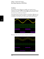
At this point, the waveform generator outputs a PWM waveform with the
specified modulation parameters (if the output is enabled).
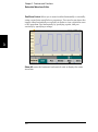
Of course, to really view the PWM waveform, you would need to output it
to an oscilloscope. If you do this, you will see how the pulse width varies,
in this case, from 80 to 120 s. At a modulation frequency of 5 Hz, the
deviation is quite visible.
43
Chapter 2 Front-Panel Menu Operation
To Output a Frequency Sweep
To Output a Frequency Sweep
2
In the frequency sweep mode, the waveform generator moves from the
start frequency to the stop frequency at a sweep rate which you specify.
You can sweep up or down in frequency, and with either linear or
logarithmic spacing, or using a list of frequencies. For this example, you
will output a swept sine wave from 50 Hz to 5 kHz.
1 Select the function and amplitude for the sweep.
For sweeps, you can select sine, square, ramp, pulse, triangle, or PRBS
waveforms (arbitrary waveforms, noise, and DC are not allowed). For
this example, select a sine wave with an amplitude of 5 Vpp.
44
Chapter 2 Front-Panel Menu Operation
To Output a Frequency Sweep
2 Select the sweep mode.
Press
and then verify that the linear sweep mode is currently
selected on the second softkey. Press the Sweep softkey to turn sweep
on. Notice the “Linear Sweep” status message at the top of the tab for the
current channel. The
button is also illuminated.
3 Set the start frequency.
Press the Start Freq softkey and then set the value to 50 Hz using the
numeric keypad or the knob and cursor keys.
4
45
2
Chapter 2 Front-Panel Menu Operation
To Output a Frequency Sweep
4 Set the stop frequency.
2
Press the Stop Freq softkey and then set the value to 5 kHz using the
numeric keypad or the knob and cursor keys. At this point, the waveform
generator outputs a continuous sweep from 50 Hz to 5 kHz if output is
enabled.
Note: If desired, you can press the
button and then press the
fourth softkey to set the frequency boundaries of the sweep using a center
frequency and frequency span. These parameters are similar to the start
frequency and stop frequency and are included to give you added
flexibility. To achieve the same results, set the center frequency to 2.525
kHz and the frequency span to 4.950 kHz.
To generate a frequency sweep, press
twice. The first press puts
the trigger in manual mode, and the second one sends a trigger. For
more information, see “To Trigger a Sweep or Burst” on page 50.
46
Chapter 2 Front-Panel Menu Operation
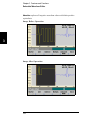
To Output a Burst Waveform
To Output a Burst Waveform
You can use the waveform generator to output a waveform with a
specified number of cycles, called a burst. You can control the amount of
time that elapses between bursts with the internal timer or the signal
level on the rear-panel Ext Trig connector. For this example, you will
output a three-cycle sine wave with a 20 ms burst period.
4
1 Select the function and amplitude for the burst.
For burst waveforms, you can select sine, square, ramp, pulse, arbitrary
waveforms, triangle, or PRBS. Noise is allowed only in the “gated” burst
mode and DC is not allowed. For this example, select a sine wave with an
amplitude of 5 Vpp.
47
2
Chapter 2 Front-Panel Menu Operation
To Output a Burst Waveform
2 Select the burst mode.
Press
and then press the Burst Off / On softkey. Notice that a
status message “N Cycle Burst, Trig Imm” is shown in the tab of the
current channel.
2
3 Set the burst count.
Press the # of Cycles softkey and then set the count to “3” using the
numeric keypad or knob. Press the Enter softkey to finish data entry if
you are using the numeric keypad.
48
Chapter 2 Front-Panel Menu Operation
To Output a Burst Waveform
4 Set the burst period.
Press the Burst Period softkey and then set the period to 20 ms using the
numeric keypad or the knob and cursor keys. The burst period sets the
time from the start of one burst to the start of the next burst.
2
4
At this point, the waveform generator outputs a continuous three-cycle
burst at 20 ms intervals.
You can generate a single burst (with the specified count) by pressing
the
key. For more information, see “To Trigger a Sweep or Burst”
on page 50.
You can also use the external gate signal to create gated bursts, where a
burst is produced while a gate signal is present on the input.
49
Chapter 2 Front-Panel Menu Operation
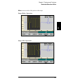
To Trigger a Sweep or Burst
To Trigger a Sweep or Burst
2
You can issue triggers from the front panel for sweeps and bursts using
one of four different trigger types.
• Immediate or “automatic” triggering is the default setting. In this
mode, the waveform generator outputs continuously when the sweep
or burst mode is selected.
• Ext or “external” triggering controls triggering via the Trigger
connector on the rear of the instrument.
• Manual triggering initiates one sweep or outputs one burst each time
you press the
button. Continue pressing this key to re-trigger
the waveform generator.
• Timer issues one or more triggers separated in time by a fixed
amount.
If sweep or burst is on, pressing
will display the trigger menu.
The illuminated
key (solid or blinking) indicates that one or both
channels are in a triggerable mode and awaiting a manual trigger. Solid
illumination occurs when the trigger menu is selected, and flashing
illumination occurs when the trigger menu is not selected. The
key is disabled when the instrument is in remote.
Pressing
when the button is solidly illuminated will cause a
manual trigger. Pressing
when the button is flashing will select
the trigger menu, and a second press will cause a manual trigger.
50
Chapter 2 Front-Panel Menu Operation
To Store the Instrument State
To Store the Instrument State
You can store instrument states in any number of state files, which
always have a .sta extension. You can do this for backup purposes, or you
can save your state to a USB drive and then reload the state on a
different instrument in order to have instruments with matching
configurations.
4
1 Select the desired storage location.
Press
and then press the Store / Recall softkey, followed by the
Store State softkey.
2 Specify the name for the selected location.
Use the knob and arrows to enter the file name.
• To add characters, press the right-cursor key until the cursor is to the
right of the existing name and then turn the knob.
51
2
Chapter 2 Front-Panel Menu Operation
To Store the Instrument State
• To delete a character, rotate the knob until you get to the blank
character before the capital A.
• To delete all characters from the cursor position to the end of the line,
press the +/- key.
2
• To use numbers in the name, you can enter them directly from the
numeric keypad.
3 Store the instrument state.
Press the STORE STATE softkey. A stored state contains the selected
function, frequency, amplitude, DC offset, duty cycle, symmetry, as well
as any modulation parameters in use. The instrument does not store
volatile waveforms created in the arbitrary waveform function.
4 Recall the instrument state (optional).
If at some later time you wish to restore (retrieve) a stored state, press
and then Store / Recall. Then press Recall State, select the state
to recall and press Select.
52
Chapter 2 Front-Panel Menu Operation
To Configure the Remote Interface
To Configure the Remote Interface
The Agilent 33500 Series supports remote interface communication
using a choice of three interfaces: GPIB (optional), USB, and LAN (LXI
Class C compliant). All three interfaces are “live” at power up. The
following sections explain how to configure the remote interface from the
instrument front panel.
4
Note: Two CDs, provided with your instrument, contain connectivity
software to enable communications over the remote interfaces. See
“Connectivity Software and Product CDs” on page 174 for further
information on these CDs and the software they contain.
GPIB Configuration (Option 400)
You need only select a GPIB address.
1 Select the “I/O” menu.
Press
and then press the I/O Config and GPIB Settings softkeys.
Then press the GP-IB Address softkey.
53
2
Chapter 2 Front-Panel Menu Operation
To Configure the Remote Interface
2 Set the GPIB address.
Use the knob and cursor keys or the numeric keypad to select a GPIB
address in the range 0 through 30 (the factory default is “10”). Press
Enter when done if you are using the numeric keypad
2
USB Configuration
The USB interface requires no front panel configuration parameters.
Just connect the Agilent 33500 Series to your PC with the appropriate
USB cable. The interface will configure itself. The instrument supports
both USB 1.1 and USB 2.0.
54
Chapter 2 Front-Panel Menu Operation
To Configure the Remote Interface
LAN Configuration
There are several parameters that you might need to set to establish
network communication using the LAN interface. Primarily, you will
need to establish an IP address. You might need to contact your network
administrator for help in establishing communication with the LAN
interface.
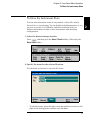
1 Select the “I/O” menu.
Press
4
and then press the I/O Config softkey.
55
2
Chapter 2 Front-Panel Menu Operation
To Configure the Remote Interface
2 Select the LAN Settings menu.
Press the LAN Settings softkey.
2
You can select Modify Settings to change the LAN settings, or you can
turn LAN Services on and off or restore the LAN settings to default values.
56
Chapter 2 Front-Panel Menu Operation
To Configure the Remote Interface
3 Press Modify Settings.
2
4
To access most items on this screen, you must use the first softkey to
switch from DHCP to Manual. With DHCP on, an IP address will
automatically be set by DHCP (Dynamic Host Configuration Protocol)
when you connect the instrument to the network, provided the DHCP
server is found and is able to do so. DHCP also automatically deals with
the subnet mask and gateway address, if required. This is typically the
easiest way to establish LAN communication for your instrument. All you
need to do is leave DHCP on. Contact your LAN administrator for more
information.
57
Chapter 2 Front-Panel Menu Operation
To Configure the Remote Interface
4 Establish an “IP Setup.”
2
If you are not using DHCP (if you have pressed the first softkey to switch
DHCP to Manual), you must establish an IP setup, including an IP
address, and possibly a subnet mask and gateway address. The IP
Address and Subnet Mask buttons are on the main screen, and you
press More to get to the Gateway configuration feature.
Contact your network administrator for the IP address, subnet mask,
and gateway to use. All IP addresses take the dot-notation form
“nnn.nnn.nnn.nnn” where “nnn” in each case is a byte value in the range
0 through 255. You can enter a new IP address using the numeric keypad
(not the knob). Just type in the numbers and the period delimiters using
the keypad. Use the left cursor key as a backspace key. Do not enter
leading zeros. For further information, see “More about IP Addresses and
Dot Notation” at the end of this section.
58
Chapter 2 Front-Panel Menu Operation
To Configure the Remote Interface
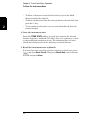
5 Configure the “DNS Setup” (optional).
DNS (Domain Name Service) is an Internet service that translates
domain names into IP addresses. Ask your network administrator
whether DNS is in use, and if it is, for the host name, domain name, and
DNS server address to use.
a. Set the “Host Name.” Press the Host Name softkey and enter the
host name. The host name is the host portion of the domain name,
which is translated into an IP address. The host name is entered as 4
a
string using the knob and cursor keys to select and change
characters. The host name may include letters, numbers, and dashes
(“-”). You can use the keypad for the numeric characters only.
b. Set the “DNS Server” addresses. From the LAN configuration
screen, press More to go to the second of the three pages.
Enter the Primary DNS and Second DNS. See your network
administrator for details.
59
2
Chapter 2 Front-Panel Menu Operation
To Configure the Remote Interface
More about IP Addresses and Dot Notation
2
Dot-notation addresses (“nnn.nnn.nnn.nnn” where “nnn” is a byte value)
such as IP addresses must be expressed with care. This is because
most web software on the PC will interpret byte values with leading zeros
as octal numbers. Thus, ”255.255.020.011” is actually equivalent to the
decimal ”255.255.16.9” rather than ”255.255.20.11” because ”.020” is
interpreted as ”16” expressed in octal, and ”.011” as ”9”. To avoid
confusion it is best to use only decimal expressions of byte values (0 to
255), with no leading zeros.
The Agilent 33500 Series assumes that all IP addresses and other dotnotation addresses are expressed as decimal byte values, and strips all
leading zeros from these byte values. Thus, if you try to enter
"255.255.020.011" in the IP address field, it becomes "255.255.20.11" (a
purely decimal expression). You should enter exactly the same
expression, "255.255.20.11" in your PC web software to address the
instrument. Do not use "255.255.020.011"—the PC will interpret that
address differently due to the leading zeros.
60
Chapter 2 Front-Panel Menu Operation
To Set up an Arbitrary Waveform
To Set up an Arbitrary Waveform
The Agilent 33500 Series includes an embedded waveform editor that
allows you to create and edit arbitrary waveforms. You can create these
waveforms by editing voltage values directly or by using any
combination of up to 12 different kinds of standard waveforms.
The following tutorial shows you how to create and edit a basic
waveform.
4
Insert Built-in Waveforms
1 Start the embedded waveform editor by pressing
and Arb,
then Arbs. Press Edit New, accept the default file name, and then
Start Editor. You now have a 0 VDC waveform of exactly 8 points.
61
2
Chapter 2 Front-Panel Menu Operation
To Set up an Arbitrary Waveform
2
2 Press Insert Built-in, then Choose Wave. Use the knob or the
arrows below the knob to select D-Lorentz and press OK. Use the
keypad and the V softkey that appears when you start typing on
the keypad to set the Amplitude to 2 V, then press OK. The
waveform now has 108 points, as the D-Lorentz waveform of 100
points was inserted in front of the initial 8 points.
3 Suppose that you want to undo the change that you just made.
Press
, then the Undo softkey. You are now back to the
original 8 point, 0 V waveform.
62
Chapter 2 Front-Panel Menu Operation
To Set up an Arbitrary Waveform
4 To put the D-Lorentz waveform back, press Redo. Then press
Done to exit.
2
4
5 Now we will insert a sine wave. Begin by pressing Choose Wave.
Make sure Sine (the default) is highlighted, and press OK. For
help in understanding the various parameters on the screen,
press Parameter Help. Then press Done to exit the help screen.
63
Chapter 2 Front-Panel Menu Operation
To Set up an Arbitrary Waveform
6 Using the numeric keypad and the up and down arrow softkeys,
set the Amplitude to 3.5 V, the Cycles to 4, and the Points to 200.
Leave all other settings at their default values and press OK.
2
7 Notice that the first softkey, Select Point # is highlighted. Put the
marker on the 270th waveform point by using the numeric
keypad to enter the number 270 and pressing Enter.
64
Chapter 2 Front-Panel Menu Operation
To Set up an Arbitrary Waveform
8 Press Choose Wave, select Square and then press OK. Set the
Amplitude to 3 V, the Offset to -2 V, the Cycles to 8, and the
Points to 100. Press OK. Notice that the 8 square wave cycles
have been inserted, beginning at the marker. Press Done.
2
4
65
Chapter 2 Front-Panel Menu Operation
To Set up an Arbitrary Waveform
Edit Waveform Characteristics
2
1 Press Edit Params and then set the Sampling Rate to 100 Sa/s. Press
Cycle Period and notice that it has been set to 4.08 seconds. This is
because you have 408 sample points in the waveform, and the
sample rate is 100 Sa/s.
2 Change the Cycle Period to 2.04 seconds and then press the
Sampling Rate softkey. It will now be set to 200 Sa/s in order to
play the 408 point waveform in 2.04 seconds.
66
Chapter 2 Front-Panel Menu Operation
To Set up an Arbitrary Waveform
3 Press Done to exit the parameter editing screen. Press Edit Points
and notice that the Point # softkey is highlighted. Enter the
number 160 and press Enter to move the marker.
2
4
4 Press Voltage and change the voltage of the selected point to
4.2 V. Press Point # and change the point marker to 150 to move
the marker off the point. When you press Enter to finish entering
point 150, you will see the 4.2 V anomaly in the wave that you
just created at point 160.
67
Chapter 2 Front-Panel Menu Operation
To Set up an Arbitrary Waveform
Zoom and Pan
2
1 To see the point in detail, press
, then Pan/Zoom Control.
Notice that the first softkey is set to Horizontal, meaning that the
zooming that we are about to do will be along the horizontal
(time) axis. Change the Zoom to 500%, and the sine wave anomaly
will be more obvious.
2 Now set the first softkey to Vertical to zoom vertically. Set the
Zoom to 500%. Notice that we have zoomed in on the voltage axis,
but we are too low to see the 4.2 V anomaly in the sine wave.
68
Chapter 2 Front-Panel Menu Operation
To Set up an Arbitrary Waveform
3 Press Pan and set the Pan to 3 V in order to move higher on the
waveform. The 4.2 V point is now clearly visible.
2
4
4 To see the entire waveform again, press Show All. Then press
Done and Done again to return to the Edit Points screen.
69
Chapter 2 Front-Panel Menu Operation
To Set up an Arbitrary Waveform
Insert, Remove, Copy and Paste Points
1 Press Insert Point 15 times and watch the display carefully. You
will see 15 new waveform points at the same voltage level.
2
2 Change the Point # to 220 and press Remove Point 20 times,
watching the display carefully as you do so in order to see the
points being removed from the waveform.
70
Chapter 2 Front-Panel Menu Operation
To Set up an Arbitrary Waveform
3 You can also edit points by using a table of voltages. Press
Advanced Edit and then Edit Via Table. Set Point # to 200, and then
set the Voltage for point 200 to 3 V. Use the knob to move between
rows and set the Voltage for points 205 and 210 to 3 V. Press Done.
2
4
4 Notice the three 3 V spikes that you just made in the waveform at
points 200, 205, and 210.
71
Chapter 2 Front-Panel Menu Operation
To Set up an Arbitrary Waveform
5 Press Cut/Copy Paste, and set Marker 1 to 150. Then press the first
softkey and change the Marker to Marker 2. Set Marker 2 to 300. The
range defined by the markers is now highlighted in black.
2
6 Press Copy, then Paste, and then At Start. Notice that section you
copied is now duplicated at the beginning of the waveform.
72
Chapter 2 Front-Panel Menu Operation
To Set up an Arbitrary Waveform
7 Now press Paste and At End. The same section of the waveform
now also appears at the very end.
2
4
8 Now press Paste and change the Point # to 500. Then press OK,
and the same portion of the waveform will be pasted in at point
500. Press Done to leave the Cut/Copy Paste menu
73
Chapter 2 Front-Panel Menu Operation
To Set up an Arbitrary Waveform
Perform Math
2
The embedded waveform editor allows you to perform
mathematical operations on the waveform. First you set markers
to define the range of the waveform that you want to modify. You
can then add, subtract or multiply that portion of the waveform
by another waveform, or you can transform the waveform in
ways that do not involve other waveforms.
1 Press Perform Math. Set Marker 1 to 400 and Marker 2 to 500.
74
Chapter 2 Front-Panel Menu Operation
To Set up an Arbitrary Waveform
2 Press Add, then select Haversine and OK. Set the Amplitude to 3V,
the Offset to 0 V, and press OK. Notice that the highlighted
section now rises in the middle as a result of the haversine
addition.
2
4
3 Now press Multiply and select the Sine wave (press OK). Set the
Cycles to 2 and press OK.
75
Chapter 2 Front-Panel Menu Operation
To Set up an Arbitrary Waveform
4 Now set Marker 1 to 200 and Marker 2 to 600.
2
5 Press Advanced Math, select Mirror and then OK
6 Continue learning about the interface by trying other Advanced
Math features, such as Invert, Absolute, Scale, and so on. Press the
Operation Help for details on these features.
76
3
3
Features and Functions
Features and Functions
This chapter makes it easy to look up details about a particular feature
of the waveform generator. It covers both front panel and remote
interface operation. You may want to read chapter 2, “Front-Panel Menu
Operation” first. See chapter 4, “Remote Interface Reference” for a
detailed discussion of the syntax of the SCPI commands to program the
waveform generator. This chapter is divided into the following sections:
• Output Configuration, on page 80
• Pulse Waveforms, on page 98
• Amplitude Modulation (AM), on page 102
• Frequency Modulation (FM), on page 107
• Phase Modulation (PM), on page 113
3
• Frequency-Shift Keying (FSK) Modulation, on page 119
• Pulse Width Modulation (PWM), on page 123
• Frequency Sweep, on page 132
• Burst Mode, on page 141
• Triggering, on page 150
• Dual Channel Operations (33522A Only), on page 156
• System-Related Operations, on page 163
• Remote Interface Configuration, on page 174
• Calibration Overview, on page 186
• Factory Default Settings, on page 211
Throughout this manual “default” states and values are identified. These
are the power-on default states provided you have not enabled the
power-down recall mode (see “Instrument State Storage” on page 163).
78
Chapter 3 Features and Functions
Throughout this manual, the following conventions are used for
SCPI command syntax for remote interface programming:
• Square brackets ( [ ] ) indicate optional keywords or parameters.
• Braces ( { } ) enclose parameters within a command string.
• Triangle brackets ( < > ) enclose parameters for which you must
substitute a value.
• A vertical bar ( | ) separates multiple parameter choices.
3
79
Chapter 3 Features and Functions
Output Configuration
Output Configuration
This section contains information to help you configure the waveform
generator for outputting waveforms. You may never have to change some
of the parameters discussed here, but they are provided to give you
flexibility.
Multi-Channel operation:
3
For waveform generators with two channels, most commands may be
preceded by the SCPI “SOURce1:” or “SOURce2:” (abbreviated “SOUR1:”
or “SOUR2:”) to explicitly direct the command to a certain channel. If the
SOURceN keyword is not used, the default instrument behavior is to
direct the command to Channel 1.
For example the command “VOLT 2.5” will set the output voltage on
Channel 1 to 2.5 volts. The command “SOUR2:VOLT 1.414” will set the
output voltage on channel 2 to 1.414 volts.
Output Function
The waveform generator can output eight standard waveforms: sine,
square, ramp, pulse, triangle, gaussian noise, PRBS (pseudo-random
binary sequence), and DC. You can also select one of nine built-in
arbitrary waveforms or create your own custom waveforms.
The 33500 Series includes an embedded waveform editor. You can use
this editor to generate point-by-point arbitrary waveforms, which allows
you to create large and complex waveforms.
80
Chapter 3 Features and Functions
Output Configuration
The table below shows which output functions are allowed with
modulation, sweep, and burst. Each “ ” indicates a valid combination. If
you change to a function that is not allowed with modulation, sweep, or
burst, then the modulation or mode is turned off.
Carrier
AM
FM
PM
FSK
Sine and Square
Pulse
Triangle and Ramp
Gaussian Noise
PRBS
Single Arb
Sequenced Arb
BPSK PWM
(b)
(b)
Sum
Burst Sweep
(a)
3
(a) Gated burst only
(b) Applies to sample clock, not whole waveform
• Function Limitations: If you change to a function whose maximum
frequency is less than that of the current function, the frequency is
adjusted to the maximum value for the new function. For example,
if you are currently outputting a 30 MHz sine wave and then change
to the ramp function, the waveform generator will automatically
adjust the output frequency to 200 kHz (the upper limit for ramps).
• Amplitude Limitations: If you change to a function whose maximum
amplitude is less than that of the current function, the amplitude is
automatically adjusted to the maximum value for the new function.
This may occur when the output units are Vrms or dBm due to the
differences in crest factor for the various output functions.
For example, if you output a 5 Vrms square wave (into 50 ohms) and
then change to the sine wave function, the waveform generator will
automatically adjust the output amplitude to 3.536 Vrms (the upper
limit for sine in Vrms).
• The Amplitude and Offset cannot be set such that they combine to
exceed the instrument’s capability. Whichever one you set last in this
situation will be modified to remain within the instrument’s limits.
81
Chapter 3 Features and Functions
Output Configuration
• You may protect a device under test (DUT) by specifying upper and
lower voltage limits for the waveform amplitude.
• Front-Panel Operation: To select a function, press
. Press
(33521A) or
or
(33522A) and then set the Output
softkey to ON to output the currently selected waveform. To view the
other waveform choices, press
to see the first page of the list,
and then press the More softkey to see the rest of the list.
3
For example, to specify a DC signal from the front panel, press
, then More and DC. Enter the Offset with the knob or
keypad, and if you use the keypad, press mV or V to finish entering
the value. Then press
or
or
and make sure the
Output softkey is ON.
• Remote Interface Operation:
FUNCtion
{SINusoid|SQUare|RAMP|PULSe|NOISe|DC|PRBS|ARB}
You can also use the APPLy command to select the function, frequency,
amplitude, and offset with a single command.
82
Chapter 3 Features and Functions
Output Configuration
Output Frequency
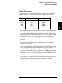
As shown below, the output frequency range depends on the function
currently selected. The default frequency is 1 kHz for all functions.
Function
Minimum Frequency
Maximum Frequency
Sine
Square
Ramp/Tri.
Pulse
PRBS
Arb
1 Hz
1 Hz
1 Hz
1 Hz
1 bps
1 Sa/s
30 MHz
30 MHz
200 kHz
30 MHz
50 Mbps
250 MSa/s
3
• Function Limitations: If you change to a function whose maximum
frequency is less than that of the current function, the frequency is
adjusted to the maximum value for the new function. For example,
if you are currently outputting a 20 MHz sine wave and then change
to the ramp function, the waveform generator will automatically
adjust the output frequency to 200 kHz (the upper limit for ramps and
triangles).
• Burst Limitation: For internally-triggered bursts, the minimum
frequency is 126 Hz.
• Duty Cycle Limitations: For Square and Pulse, Duty Cycle is limited
by the 16-ns minimum pulse width specification. For example, at 1
kHz, Duty Cycle may be adjusted as low as 0.01% because that would
result in a pulse width of 100 ns. However, at 1 MHz the minimum
Duty Cycle is 1.6%, and at 10 MHz it’s 16%. At 30 MHz, Duty Cycle
may only be adjusted from 48% to 52%.
If you change to a frequency that cannot produce the current duty cycle,
the duty cycle is automatically adjusted in order to meet the
minimum pulse width specification.
83
Chapter 3 Features and Functions
Output Configuration
• Front-Panel Operation: To set the output frequency, press the
button, then the Frequency softkey for the selected function. Then
use the knob or numeric keypad to enter the desired frequency. To set
the waveform period instead, press
and then press the
Frequency softkey to toggle to the setting to Period.
• Remote Interface Operation:
[SOURce[1|2]:]FREQuency {<frequency>|MINimum|MAXimum}
You can also use the APPLy command to select the function, frequency,
amplitude, and offset with a single command.
3
Output Amplitude
The default amplitude is 100 mVpp (into 50 ohms) for all functions.
• Offset Voltage Limitations: The relationship between output
amplitude and offset voltage is shown below. Vmax is the maximum
peak voltage for the selected output termination (±5 volts for a 50
load or ±10 volts for a high-impedance load).
Vpp < 2(Vmax – |Voffset|)
• Limits Due to Output Termination: If you change the output
termination setting, the displayed output amplitude will be adjusted
to reflect the new setting, but the actual amplitude of the output signal
will not be changed. For example, if you set the amplitude to 10 Vpp
and then change the output termination from 50 ohms to “high
impedance”, the amplitude displayed on the waveform generator’s
front-panel will double to 20 Vpp. If you change from “high
impedance” to 50 ohms, the displayed amplitude will drop in half. For
more information, see “Output Termination” on page 89.
• Limits Due to Units Selection: In some cases, the amplitude limits
are determined by the output units selected. This might occur when
the units are Vrms or dBm due to the differences in crest factor for
the various output functions. For example, if you output a 5 Vrms
square wave (into 50 ohms) and then change to the sine wave
function, the waveform generator will automatically adjust the
output amplitude to 3.536 Vrms (the upper limit for sine waves in
Vrms).
84
Chapter 3 Features and Functions
Output Configuration
• You can set the output amplitude in Vpp, Vrms, or dBm. For more
information, see “Output Units” on page 88.
• You cannot specify the output amplitude in dBm if the output
termination is currently set to “high impedance”. The units are
automatically converted to Vpp. For more information, see “Output
Units” on page 88.
• Arbitrary Waveform Limitations: For arbitrary waveforms, the
maximum amplitude will be limited if the waveform data points do
not span the full range of the output DAC (Digital- to-Analog Converter).
For example, the built-in “Sinc” waveform does not use the full range
of values between ±1 and therefore its maximum amplitude is limited
to 6.087 Vpp (into 50 ohms).
• While changing amplitude, you may notice a momentary disruption
in the output waveform at certain voltages due to switching of the
output attenuators. To prevent this disruption in the output, you can
disable the voltage autoranging feature as described on page 93.
• You can also set the amplitude and offset voltage by specifying a high
level and low level. For example, if you set the high level to +2 volts
and the low level to -3 volts, the resulting amplitude is 5 Vpp (with an
offset voltage of -500 mV).
• For a DC signal, the output level is actually controlled by setting the
offset voltage. You can set the DC level to any value between -5 V and
+5 V with a 50 load or -10 to +10 VDC with a high-impedance load.
See “DC Offset Voltage” on the following page for more information.
• To select a DC signal from the front panel, press
, then More
and DC. Enter the Offset with the knob or keypad, and if you use
the keypad, press mV or V to finish entering the value. Then press
or
or
and make sure the Output softkey is ON.
• Front-Panel Operation: To set the output amplitude, press
and
then the Amplitude softkey for the selected function. Then use the
knob or numeric keypad to enter the desired amplitude. To set the
amplitude using a high level and low level, press
and then
press the Amp/Offs softkey to toggle it to High/Low.
85
3
Chapter 3 Features and Functions
Output Configuration
• Remote Interface Operation:
VOLTage {<amplitude>|MINimum|MAXimum}
Or, you can set the amplitude by specifying a high level and low level
using the following commands.
VOLTage:HIGH {<voltage>|MINimum|MAXimum}
VOLTage:LOW {<voltage>|MINimum|MAXimum}
You can also use the APPLy command to select the function, frequency,
amplitude, and offset with a single command.
3
DC Offset Voltage
The default offset is 0 volts for all functions.
• Limits Due to Amplitude: The relationship between offset voltage and
output amplitude is shown below. The peak output voltage (DC plus
AC) cannot exceed the instrument output rating (±5 V into 50 load,
or ±10 V into a high impedance load).
• Vmax is the maximum peak voltage for the selected output
termination (±5 V for a 50 Ω load or ±10 V for a high-impedance load).
|Voffset| < Vmax – Vpp/2
If the specified offset voltage is not valid, the waveform generator will
automatically adjust it to the maximum DC voltage allowed with the
amplitude specified.
• Limits Due to Output Termination: The offset limits are determined
by the current output termination setting. For example, if you set the
offset to 100 mVDC and then change the output termination from
50 ohms to high impedance, the offset voltage displayed on the
waveform generator’s front-panel will double to 200 mVDC (and no
error will be generated). If you change from high impedance to
50 ohms, the displayed offset will drop in half. See “Output
Termination” on page 89 for more information.
86
Chapter 3 Features and Functions
Output Configuration
• Arbitrary Waveform Limitations: For arbitrary waveforms, the
maximum offset and amplitude will be limited if the waveform data
points do not span the full range of the output DAC (Digital-to-Analog
Converter).
• You can also set the offset by specifying a high level and low level.
For example, if you set the high level to +2 volts and the low level to
-3 volts, the resulting amplitude is 5 Vpp (with an offset voltage of
-500 mV).
• For the DC volts function, you control the output level by setting the
offset voltage. You can set the DC level to any value between ±5 VDC
into 50 ohms or ±10 VDC into an open circuit.
Front-Panel Operation: To select a DC signal from the front panel,
press
, then More and DC. Enter the Offset with the knob or
keypad, and if you use the keypad, press mV or V to finish entering
the value. Then press
or
or
and make sure the
Output softkey is ON.
• Remote Interface Operation:
[SOURce[1|2]:]VOLTage:OFFSet
{<offset>|MINimum|MAXimum}
Or, you can set the offset by specifying a high level and low level
using the following commands.
[SOURce[1|2]:]VOLTage:HIGH
{<voltage>|MINimum|MAXimum}
[SOURce[1|2]:]VOLTage:LOW
{<voltage>|MINimum|MAXimum}
You can also use the APPLy command to select the function, frequency,
amplitude, and offset with a single command.
87
3
Chapter 3 Features and Functions
Output Configuration
Output Units
Applies to output amplitude only. At power-on, the units for output
amplitude are volts peak-to-peak.
• Output units: Vpp (default), Vrms, or dBm.
• The unit setting is stored in volatile memory. The units are set to
“Vpp” when power has been off or after a remote interface reset
(provided the Power On state is set to Factory).
3
• The waveform generator uses the current units selection for both
front panel and remote interface operations. For example, if you
select “VRMS” from the remote interface, the units are displayed as
“VRMS” on the front panel.
• The output units for amplitude cannot be set to dBm if the output
termination is currently set to “high impedance”. This is because
calculating dBm requires a finite load impedance. In this case, the
units are automatically converted to Vpp.
• Front-Panel Operation: Use the numeric keypad to enter the desired
magnitude and then press the appropriate softkey to select the units.
You can also convert from one unit to another from the front panel.
For example, to convert 2 Vpp to its equivalent value in Vrms,
press
and then press the Ampl As softkey, then the Vrms
softkey. The converted value is 707.1 mVrms for a sine wave.
• Remote Interface Operation:
VOLTage:UNIT {VPP|VRMS|DBM}
88
Chapter 3 Features and Functions
Output Configuration
Output Termination
Applies to output amplitude and offset voltage only. The 33500 Series has
a fixed series output impedance of 50 ohms to the front-panel channel
output connectors. If the actual load impedance is different than the
value specified, the displayed amplitude and offset levels will not reflect
actual voltages at the load.
• Output termination: 1 to 10 k, or infinite. The default is 50 .
The tab at the top of each channel indicates the value of this setting.
3
• If you specify a 50-ohm termination but are actually terminating into
an open circuit, the actual output will be twice the value specified.
For example, if you set the DC offset to 100 mVDC (and specify a 50
load) but are terminating the output into an open circuit, the actual
offset will be 200 mVDC.
• If you change the output termination setting, the displayed output
amplitude and offset levels are automatically adjusted (no error will
be generated). For example, if you set the amplitude to 10 Vpp and
then change the output termination from 50 ohms to high impedance,
the amplitude displayed on the waveform generator’s front-panel will
double to 20 Vpp. If you change from “high impedance” to 50 ohms, the
displayed amplitude and offset will drop in half. This changes the
displayed value, not the generated output voltage.
• You cannot specify the output amplitude in dBm if the output
termination is currently set to high impedance. The units are
automatically converted to Vpp.
• You cannot change the output termination if voltage limits are
enabled, because the instrument cannot know which output
termination settings the voltage limits apply to. To change output
termination, disable voltage limits, set the new termination value,
adjust the voltage limits, and re-enable voltage limits.
89
Chapter 3 Features and Functions
Output Configuration
• Front-Panel Operation: Press
or
or
and select the
Output Load softkey. Then press Set To 50 , Set To High Z, or Load.
If you select Load, use the knob or numeric keypad to select the
impedance.
• Remote Interface Operation:
OUTPut[1|2]:LOAD {<ohms>|INFinity|MINimum|MAXimum}
3
90
Chapter 3 Features and Functions
Output Configuration
Duty Cycle (Square Waves)
The duty cycle of a square wave represents the fraction of time per cycle
that the square wave is at a high level (assuming that the waveform is
not inverted).
20% Duty Cycle
3
80% Duty Cycle
(See Pulse Waveforms, on page 98 for information about duty cycle for
pulse waveforms.)
• Duty Cycle: 0.01% to 99.99% at low frequencies; range is reduced at
higher output frequency.
• The duty cycle is stored in volatile memory; the default value is 50%.
• The duty cycle setting is remembered when you change from square
wave to another function. The duty cycle setting does not apply to a
square waveform used as the modulating waveform for AM, FM, PM
or PWM. A 50% duty cycle is always used for a modulating square
waveform. The duty cycle setting applies only to a square waveform
carrier.
• Front-Panel Operation: After selecting the square wave function,
press the Duty Cycle softkey. Then use the knob or numeric keypad
to enter the desired duty cycle. If you use the numeric keypad, press
Percent to complete the entry.
• Remote Interface Operation:
FUNCtion:SQUare:DCYCle {<percent>|MINimum|MAXimum}
The APPLy command automatically sets the duty cycle to 50%.
91
Chapter 3 Features and Functions
Output Configuration
Symmetry (Ramp Waves)
Applies to ramp waves only. Symmetry represents the fraction of each
cycle that the ramp wave is rising (assuming that the waveform is not
inverted).
3
0% Symmetry
100% Symmetry
• The symmetry is stored in volatile memory; the default value is 100%.
• The symmetry setting is remembered when you change from ramp to
another waveform. When you return to the ramp waveform, the
previous symmetry value is used.
• If you select a ramp waveform as the modulating waveform for AM,
FM, PM, or PWM, the symmetry setting does not apply.
• Front-Panel Operation: After selecting the ramp function, press the
Symmetry softkey. Then press the 100%, 50%, or 0% softkey or press
Symmetry and use the knob or numeric keypad to enter the desired
symmetry. If you use the numeric keypad, press Percent to complete
the entry.
• Remote Interface Operation:
FUNCtion:RAMP:SYMMetry {<percent>|MINimum|MAXimum}
The APPLy command automatically sets the symmetry to 100%.
92
Chapter 3 Features and Functions
Output Configuration
Voltage Autoranging
Autoranging is enabled by default and the waveform generator
automatically selects the optimal settings for the attenuators. With
autoranging disabled, the waveform generator uses the current attenuator
settings and does not switch attenuator relays.
• You can disable autoranging to eliminate momentary disruptions
caused by switching of the attenuators while changing amplitude.
However, turning autoranging off has side effects:
• The amplitude and offset accuracy and resolution (and waveform
fidelity) may be adversely affected when reducing the amplitude
below a range change that would occur with autoranging on.
• You may not be able to achieve the minimum amplitude that is
available with autoranging on.
• Some instrument specifications do not apply with autoranging off.
• Front-Panel Operation: Press
or
or
and press the
Range softkey again to toggle between the Auto and Hold selections.
• Remote Interface Operation:
VOLTage:RANGe:AUTO {OFF|ON|ONCE}
The APPLy command overrides the voltage autorange setting and
automatically enables autoranging.
Output Control
You can disable or enable the front-panel channel output connector. By
default, the output is disabled at power on to protect other equipment.
When a channel output connector is enabled, the corresponding
or
or
key is illuminated.
• Front-Panel Operation: Press
or
Output On/Off to enable the output.
or
followed by
• If an excessive external voltage is applied to a front-panel channel
output connector by an external circuit, the instrument will generate
an error message and disable the output. To re-enable the output,
remove the overload from the connector and press
or
or
followed by Output On/Off to enable the output.
93
3
Chapter 3 Features and Functions
Output Configuration
• Remote Interface Operation:
OUTPut[1|2] {OFF|ON}
The APPLy command overrides the current setting and automatically
enables the channel output connector.
Waveform Polarity
3
In the normal mode (default), the waveform goes positive during the first
part of the cycle. In the inverted mode, the waveform goes negative
during the first part of the cycle.
• As shown in the examples below, the waveform is inverted relative to
the offset voltage. Any offset voltage present will remain unchanged
when the waveform is inverted.
No Offset Voltage
With Offset Voltage
• When a waveform is inverted, the Sync signal associated with the
waveform is not inverted.
• Front-Panel Operation: Press
or
or
and then press
Polarity to toggle between the Normal and Inverted selections.
• Remote Interface Operation:
OUTPut[1|2]:POLarity {NORMal|INVerted}
94
Chapter 3 Features and Functions
Output Configuration
Sync Output Signal
A sync output is provided on the front-panel Sync connector. All of the
standard output functions (except DC and noise) have an associated Sync
signal. For applications where you may not want to output the Sync
signal, you can disable the Sync connector. The Sync signal may be
derived from either output channel in a two-channel instrument.
• By default the Sync signal is derived from Channel 1.
• By default, the Sync signal is routed to the Sync connector (enabled).
• When the Sync signal is disabled, the output level on the Sync
connector is at a logic “low” level.
3
• When a waveform is inverted (see “Waveform Polarity” on the previous
page), the Sync signal associated with the waveform is not inverted.
• The Sync signal setting is overridden by the setting of the marker
used with the sweep mode (see page 137). Therefore, when the marker
is enabled (and the sweep mode is also enabled), the Sync signal
setting is ignored.
• For sine, pulse, ramp, square, and triangle waveforms, the Sync
signal is a square waveform with a 50% duty cycle. The Sync signal is
“high” in the first half of the cycle and “low” in the last half. The Sync
signal’s voltage levels are TTL-compatible when its load impedance is
more than 1 k.
• For arbitrary waveforms, the Sync signal is a Marker pulse with a
rising edge at the beginning of the ARB waveform, and a falling edge
at the point number selected as Marker. The Sync signal is a TTL
“high” when the first downloaded waveform point is output. This
default behavior may be overridden by using the MARKer:POINt
command which specifies a certain point within the arbitrary
waveform at which the Sync signal will transition to “low”.
95
Chapter 3 Features and Functions
Output Configuration
• For internally-modulated AM, FM, PM, and PWM, the Sync signal is
normally referenced to the modulating waveform (not the carrier) and
is a square waveform with a 50% duty cycle. The Sync signal is a TTL
“high” during the first half of the modulating waveform. You can set
up the Sync signal to follow the carrier waveform by using the
command:
OUTPut:SYNC:MODE {CARRier|NORMal|MARKer}
when modulating with internal modulation.
3
• For externally-modulated AM, FM, PM, and PWM, the Sync signal is
referenced to the carrier waveform (not the modulating waveform)
and is a square waveform with a 50% duty cycle.
• The polarity of the Sync signal may be inverted using the SCPI
command:
OUTPut:SYNC:POLarity {INVerted|NORMal}
• For FSK, the Sync signal is referenced to the “hop” frequency. The
Sync signal is a TTL “high” on the transition to the “hop” frequency.
• For frequency sweeps with Marker Off, the Sync signal is a square
waveform with a 50% duty cycle for the duration of the sweep. The
Sync signal is a TTL “high” at the beginning of the sweep and goes
“low” at the midpoint of the sweep. The Sync signal is synchronized
with the sweep, but is not equal to the sweep time because its timing
includes the re-arm time.
• For frequency sweeps with Marker On, the Sync signal is a TTL “high”
at the beginning of the sweep and goes “low” at the marker frequency.
You can change this behavior with the OUTPut[1|2]:SYNC:MODE
MARKER command.
• You can override normal sync behavior to force Sync to always follow
the carrier waveform. The command for doing this is called
OUTPut[1|2]:SYNC:MODE CARRier; see the Agilent 33500 Series
Programmer’s Reference Help for details.
96
Chapter 3 Features and Functions
Output Configuration
• For a triggered burst, the Sync signal is a TTL “high” when the burst
begins. The Sync signal is a TTL “low” at the end of the specified
number of cycles (may not be the zero-crossing point if the waveform
has an associated start phase). For an infinite count burst, the Sync
signal is the same as for a continuous waveform.
• For an externally-gated burst, the Sync signal follows the external
gate signal. However, the signal will not go to a TTL “low” until the
end of the last cycle (may not be the zero-crossing point if the
waveform has an associated start phase).
• Front-Panel Operation: Press
and press the Sync softkey
again to toggle between Off and On. You can also press Sync Setup to
configure Sync.
• Remote Interface Operation:
OUTPut:SYNC {OFF|ON}
OUTPUT[1|2]:SYNC:MODE {CARRier|NORMal|MARKer}
OUTPUT[1|2]:SYNC:POLARITY {NORMAL|INVerted}
OUTPUT:SYNC:SOURCE {CH1|CH2}
97
3
Chapter 3 Features and Functions
Pulse Waveforms
Pulse Waveforms
As shown below, a pulse or square waveform consists of a period, a pulse
width, a rising edge, and a falling edge.
90%
90%
50%
50%
3
Pulse Width
10%
10%
Trailing Edge Time
Leading EdgeTime
Period
Period
• Period: 33.3 ns to 1,000,000 s. The default is 1 ms. Period is the
reciprocal of frequency.
• The waveform generator will adjust the pulse width and edge time as
needed to accommodate the specified period.
• Front-Panel Operation: After selecting the pulse function, press
, then the Frequency/Period softkey to toggle to Period. Then
press
, then Period. Use the knob or numeric keypad to enter
the desired pulse period.
• Remote Interface Operation:
[SOURce[1|2]:]FUNCtion:PULSe:PERiod
{<seconds>|MINimum|MAXimum}
98
Chapter 3 Features and Functions
Pulse Waveforms
Pulse Width
The pulse width represents the time from the 50% threshold of the
rising edge of the pulse to the 50% threshold of the next falling edge.
• Pulse width: 16 ns to 1,000,000 s (see restrictions below). The default
pulse width is 100 µs.
• The specified pulse width must also be less than the difference
between the period and the minimum pulse width as shown below.
The waveform generator will adjust the pulse width as needed to
accommodate the specified period.
3
Pulse Width < Period – 16 ns
• The waveform generator will automatically adjust the pulse width as
needed to accommodate the specified period.
• Front-Panel Operation: After selecting the pulse function, press the
Pulse Width softkey. Then use the knob or numeric keypad to enter
the desired pulse width.
• Remote Interface Operation:
FUNCtion:PULSe:WIDTh {<seconds>|MINimum|MAXimum}
99
Chapter 3 Features and Functions
Pulse Waveforms
Pulse Duty Cycle
The pulse duty cycle is defined as:
Duty Cycle = 100(Pulse Width)/Period
where the pulse width represents the time from the 50% threshold of the
rising edge of the pulse to the 50% threshold of the next falling edge.
• Pulse duty cycle: 0% to 100% (see restrictions below). The default is
10%.
3
• The specified pulse duty cycle must conform to the following
restrictions determined by the minimum pulse width (Wmin). The
waveform generator will adjust the pulse duty cycle as needed to
accommodate the specified period.
Duty Cycle > 100(16 ns) / Period
and
Duty Cycle < 100(1 – 16 ns / Period)
• The specified pulse duty cycle must conform to the following
restriction determined by the edge time. The waveform generator will
adjust the pulse duty cycle as needed to accommodate the specified
period.
• To achieve edges > 8.4 ns, the pulse width must be at least 20 ns. The
longer the edges, the greater the minimum pulse width. Longer edges
will therefore restrict duty cycle more than shorter edges.
• Front-Panel Operation: After selecting the pulse function, press
and toggle the Width/Duty Cyc softkey to the Duty Cyc
softkey. Then press
, followed by Duty Cycle, and use the knob
or numeric keypad to enter the desired duty cycle.
• Remote Interface Operation:
FUNCtion:PULSe:DCYCle {<percent>|MINimum|MAXimum}
100
Chapter 3 Features and Functions
Pulse Waveforms
Edge Times
The edge times set the transition times for the leading and trailing edges
of the pulse, either independently or together. For each transition
(leading or trailing edge), the edge time represents the time between the
10% and 90% thresholds.
• Edge time: 8.4 ns to 1 µs (see restrictions below). The default edge
time is 10 ns.
• The specified edge time must fit within the specified pulse width as
shown below. The waveform generator will adjust the edge time as
needed to accommodate the specified pulse width.
• Front-Panel Operation: After selecting the pulse function, press the
Edge Times softkey. Then use the Lead Edge and Trail Edge
softkeys, followed by the knob or numeric keypad to enter the desired
edge times.
• Remote Interface Operation:
FUNCtion:PULSe:TRANsition:LEADing
{<seconds>|MINimum|MAXimum}
FUNCtion:PULSe:TRANsition:TRAiling
{<seconds>|MINimum|MAXimum}
FUNCtion:PULSe:TRANsition[:BOTH]
{<seconds>|MINimum|MAXimum}
101
3
Chapter 3 Features and Functions
Amplitude Modulation (AM)
Amplitude Modulation (AM)
A modulated waveform consists of a carrier waveform and a
modulating waveform. In AM, the amplitude of the carrier is varied
by the instantaneous level of the modulating waveform. The waveform
generator will accept an internal or external modulation source. The
33500 Series offers two types of AM: DSFC (Double-Sideband, FullCarrier, the type normally used for AM radio broadcasting) and DSSC
(Double-Sideband, Suppressed Carrier).
3
For more information on the fundamentals of Amplitude Modulation,
refer to chapter 5, “Tutorial.”
To Select AM Modulation
• The 33500 Series will allow only one modulation mode to be enabled
at a time on a channel. For example, you cannot simultaneously
enable AM and FM. When you enable AM, any previous modulation
mode is turned off. The two-channel 33522A can combine the
modulated waveforms from two channels together by adding them
(see the COMBine command in the Agilent 33500 Series
Programmer’s Reference Help for details). The modulation on each
channel is independent of the modulation on the other channel. See
the PHASe:SYNChronize command in the Agilent 33500 Series
Programmer’s Reference Help for details.
• The waveform generator will not allow AM to be enabled at the same
time as sweep or burst. When you enable AM, the sweep or burst
mode is turned off.
• Front-Panel Operation: You must select AM before setting up any of
the other modulation parameters. Press
and then select AM
using the Type softkey. The AM waveform is output using the present
settings for the carrier frequency, modulating frequency, output
amplitude, and offset voltage.
• Remote Interface Operation: To avoid multiple waveform changes,
enable AM after you have set up the other modulation parameters.
AM:STATe {OFF|ON}
102
Chapter 3 Features and Functions
Amplitude Modulation (AM)
Carrier Waveform Shape
• AM carrier shape: Sine (default), Square, Pulse, Ramp, Triangle,
Noise, PRBS, or Arbitrary waveform. You cannot use DC as the
carrier waveform.
• Front-Panel Operation: Select any waveform under
except DC.
For arbitrary waveforms, press Arb and Arbs, and then choose the
Select Arb softkey to select the active waveform.
• Remote Interface Operation:
3
FUNCtion
{SINusoid|SQUare|PULSe|RAMP|ARB|NOISe|PRBS}
You can also use the APPLy command to select the function, frequency,
amplitude, and offset with a single command.
Carrier Frequency
The maximum carrier frequency depends on the function selected as
shown below. The default is 1 kHz for all functions. Arbitrary waveform
“frequency” is also set using the FUNCtion:ARBitrary:SRATe command.
Function
Minimum Frequency
Maximum Frequency
Sine
Square
Ramp
Pulse
PRBS
Noise BW
Arbs
1 Hz
1 Hz
1 Hz
1 Hz
1 mBPS
1 mHz
1 Sa/sec
30 MHz
30 MHz
200 kHz
30 MHz
50 mBPS
30 MHz
250 MSa/sec
• Front-Panel Operation: To set the carrier frequency, press the
button, then the Frequency softkey. Then use the knob or numeric
keypad to enter the desired frequency.
• Remote Interface Operation:
[SOURce[1|2]:]FREQuency {<frequency>|MINimum|MAXimum}
You can also use the APPLy command to select the function, frequency,
amplitude, and offset with a single command.
103
Chapter 3 Features and Functions
Amplitude Modulation (AM)
Modulating Waveform Shape
The waveform generator will accept an internal or external modulation
source for AM.
• Modulating waveform shape (internal source): Sine (default), Square,
UpRamp, DnRamp, Triangle, Noise, PRBS, or Arb waveform.
• Square has 50% duty cycle
• UpRamp has 100% symmetry
3
• Triangle has 50% symmetry
• DnRamp has 0% symmetry
• Noise - white gaussian noise
• PRBS - Pseudo Random Bit Sequence (polynomial PN7)
• Arb - Arbitrary waveform
• Front-Panel Operation: After enabling AM, press the Shape softkey.
• Remote Interface Operation:
AM:INTernal:FUNCtion
{SINusoid|SQUare|PULSe|RAMP|NRAMp|TRIangle|
NOISe|PRBS|ARB}
Modulating Waveform Frequency
The waveform generator will accept an internal or external modulation
source for AM.
• Modulating frequency (internal source): varies by signal type, from
1 Hz to 30 MHz. The default is 100 Hz.
• Modulating frequency (external source): 0 to 100 kHz
• Front-Panel Operation: After enabling AM modulation, press More
and then the AM Freq softkey.
104
Chapter 3 Features and Functions
Amplitude Modulation (AM)
• Remote Interface Operation:
[SOURce[1|2]:]AM:INTernal:FREQuency
{<frequency>|MINimum|MAXimum}
Modulation Depth
The modulation depth is expressed as a percentage and represents the
extent of the amplitude variation. At 0% depth, the output amplitude is
constant at one-half of the carrier’s amplitude setting. At 100% depth,
the output amplitude varies according to the modulating waveform, from
0% to 100% of the carrier’s amplitude setting.
• Modulation depth: 0% to 120%. The default is 100%.
• Even at greater than 100% depth, the waveform generator will not
exceed ±5 V peak on the output (into a 50 Ω load). To achieve
modulation depth greater than 100%, output carrier amplitude may
be reduced.
• Front-Panel Operation: After enabling AM, press the AM Depth
softkey. Then use the knob or numeric keypad to enter the depth.
• Remote Interface Operation:
AM:DEPTh {<depth_in_percent>|MINimum|MAXimum}
Double Sideband Suppressed Carrier AM
The 33500 Series supports two forms of amplitude modulation, “Normal”
and Double Sideband Suppressed Carrier (DSSC). To change between
normal AM and DSSC, use the command:
[SOURce[1|2]]:AM:DSSC {ON|OFF}.
In DSSC, the carrier is not present unless the modulating signal has an
amplitude greater than zero.
105
3
Chapter 3 Features and Functions
Amplitude Modulation (AM)
Modulating Source
The waveform generator will accept an internal or external modulation
source for AM.
• Modulating source: Internal (default), Other Channel, or External.
3
• If you select the External source, the carrier waveform is modulated
with an external waveform. The modulation depth is controlled by the
±5 V signal level present on the rear-panel Modulation In connector.
For example, if you have set the modulation depth to 100%, then
when the modulating signal is at +5 volts, the output will be at the
maximum amplitude. When the modulating signal is at -5 volts, then
the output will be at the minimum amplitude. The external modulation
input has -3 dB bandwidth of 100 kHz.
• Front-Panel Operation: After enabling AM, press the Source softkey.
• Remote Interface Operation:
AM:SOURce {INTernal|EXTernal|CH1|CH2}
106
Chapter 3 Features and Functions
Frequency Modulation (FM)
Frequency Modulation (FM)
A modulated waveform consists of a carrier waveform and a
modulating waveform. In FM, the frequency of the carrier is varied
by the instantaneous voltage of the modulating waveform.
For more information on the fundamentals of Frequency Modulation,
refer to chapter 5, “Tutorial.”
To Select FM Modulation
• The waveform generator will allow only one modulation mode to be
enabled at a time. When you enable FM, the previous modulation
mode is turned off.
• The waveform generator will not allow FM to be enabled when sweep
or burst is enabled. When you enable FM, the sweep or burst mode is
turned off.
• Front-Panel Operation: You must select FM before setting up any of
the other modulation parameters. Press
and then select FM
using the Type softkey. The FM waveform is output using the present
settings for the carrier frequency, modulating frequency, output
amplitude, and offset voltage.
• Remote Interface Operation: To avoid multiple waveform changes,
enable FM after you have set up the other modulation parameters.
FM:STATe {OFF|ON}
107
3
Chapter 3 Features and Functions
Frequency Modulation (FM)
Carrier Waveform Shape
• FM carrier shape: Sine (default), Square, Pulse, Triangle, PRBS,
UpRamp, DnRamp, or Noise. You cannot use arbitrary waveform or
DC as the carrier waveform.
• Front-Panel Operation: Press
Noise, Arb, or DC.
and select any waveform except
• Remote Interface Operation:
FUNCtion
{SINusoid|SQUare|RAMP|PULSe|PRBS|NOISe|ARB}
3
You can also use the APPLy command to select the function, frequency,
amplitude, and offset with a single command.
108
Chapter 3 Features and Functions
Frequency Modulation (FM)
Carrier Frequency
The maximum carrier frequency depends on the function selected as
shown below. The default is 1 kHz for all functions.
Function
Minimum Frequency
Maximum Frequency
Sine
Square
Ramp
Pulse
PRBS
1 Hz
1 Hz
1 Hz
1 Hz
1 mBPS
30 MHz
30 MHz
200 kHz
30 MHz
50 MBPS
• The carrier frequency must always be greater than or equal to the
frequency deviation. If you attempt to set the deviation to a value
greater than the carrier frequency (with FM enabled), the waveform
generator will automatically adjust the deviation to the maximum
value allowed with the present carrier frequency.
• The sum of the carrier frequency and deviation must be less than or
equal to the maximum frequency for the selected waveform plus 100 kHz
(30.1 MHz for sine and square, and 300 kHZ for ramp). If you attempt to
set the deviation to an invalid value, the waveform generator will
automatically adjust it to the maximum value allowed with the
present carrier frequency.
• Front-Panel Operation: To set the carrier frequency, press the
Frequency softkey (under
)for the selected function. Then use
the knob or numeric keypad to enter the desired frequency.
• Remote Interface Operation:
[SOURce[1|2]:]FREQuency {<frequency>|MINimum|MAXimum}
You can also use the APPLy command to select the function, frequency,
amplitude, and offset with a single command.
109
3
Chapter 3 Features and Functions
Frequency Modulation (FM)
Modulating Waveform Shape
The waveform generator will accept an internal or external modulation
source for FM.
• Modulating waveform shape (internal source): Sine (default), Square,
Pulse, UpRamp, DnRamp, Triangle, Noise, or PRBS.
• Square has 50% duty cycle
• UpRamp has 100% symmetry
3
• Triangle has 50% symmetry
• DnRamp has 0% symmetry
• Noise - white gaussian noise
• PRBS - Pseudo Random Bit Sequence (polynomial PN7)
• You can use noise as the modulating waveshape, but you cannot use
noise, arbitrary waveforms, or DC as the carrier waveform.
• Front-Panel Operation: After selecting FM, press the Shape softkey.
• Remote Interface Operation:
FM:INTernal:FUNCtion
{SINusoid|SQUare|RAMP|NRAMp|TRIangle|
NOISe|PRBS|ARB}
110
Chapter 3 Features and Functions
Frequency Modulation (FM)
Modulating Waveform Frequency
The waveform generator will accept an internal or external modulation
source for FM.
• Modulating frequency (internal source): 1 Hz to 30 MHz.
The default is 10 Hz.
• Front-Panel Operation: After selecting FM, press the FM Freq softkey.
• Remote Interface Operation:
[SOURce[1|2]:]FM:INTernal:FREQuency
{<frequency>|MINimum|MAXimum}
3
Frequency Deviation
The frequency deviation setting represents the peak variation in
frequency of the modulated waveform from the carrier frequency.
When the carrier is PRBS, frequency deviation causes a change in the bit
rate equal to one-half of the set frequency. For example, a 10 kHz
deviation is equivalent to a 5 KBPS change in bit rate.
• Frequency deviation: 1 Hz to (carrier frequency)/2. The default is
100 Hz.
• The carrier frequency must always be greater than or equal to the
deviation. If you attempt to set the deviation to a value greater than
the carrier frequency (with FM enabled), the waveform generator will
limit the deviation to the maximum value allowed with the present
carrier frequency.
• The sum of the carrier frequency and deviation must be less than or
equal to the maximum frequency for the selected function plus 100 kHz
(30.1 MHz for sine and square and 300 kHz for ramp). If you attempt
to set the deviation to a value that is not valid, the waveform
generator will limit it to the maximum value allowed with the present
carrier frequency.
• Front-Panel Operation: After enabling FM, press the Freq Dev softkey.
Then use the knob or numeric keypad to enter the desired deviation.
• Remote Interface Operation:
FM:DEViation {<peak_deviation_in_Hz>|MINimum|MAXimum}
111
Chapter 3 Features and Functions
Frequency Modulation (FM)
Modulating Source
The waveform generator will accept an internal or external modulation
source for FM.
• Modulating source: Internal (default), Other Channel, or External.
3
• If you select the External source, the carrier waveform is modulated
with an external waveform. The frequency deviation is controlled by
the ±5 V signal level present on the rear-panel Modulation In
connector. For example, if you have set the deviation to 10 kHz,
then a +5 V signal level corresponds to a 10 kHz increase in frequency.
Lower external signal levels produce less deviation and negative
signal levels reduce the frequency below the carrier frequency. The
external modulation input has -3 dB bandwidth of 100 kHz.
• Front-Panel Operation: After selecting FM, press the Source softkey.
• Remote Interface Operation:
FM:SOURce {INTernal|EXTernal|CH1|CH2}
112
Chapter 3 Features and Functions
Phase Modulation (PM)
Phase Modulation (PM)
A modulated waveform consists of a carrier waveform and a
modulating waveform. PM is very similar to FM, but in PM the phase of
the modulated waveform is varied by the instantaneous voltage of the
modulating waveform.
For more information on the fundamentals of Phase Modulation, refer to
chapter 5, “Tutorial.”
To Select PM Modulation
• The waveform generator will allow only one modulation mode to be
enabled at a time. When you enable PM, the previous modulation
mode is turned off.
• The waveform generator will not allow PM to be enabled when sweep
or burst is enabled. When you enable PM, the sweep or burst mode is
turned off.
• Front-Panel Operation: You must select PM before setting up any of
the other modulation parameters. Press
and then select PM
using the Type softkey. The PM waveform is output using the present
settings for the carrier frequency, modulating frequency, output
amplitude, and offset voltage.
• Remote Interface Operation: To avoid multiple waveform changes,
enable PM after you have set up the other modulation parameters.
PM:STATe {OFF|ON}
113
3
Chapter 3 Features and Functions
Phase Modulation (PM)
Carrier Waveform Shape
• PM carrier shape: Sine (default), Square, Pulse, PRBS, Ramp, or
Arbitrary waveform. You cannot use Noise or DC as the carrier
waveform.
• Front-Panel Operation: Press
and select any waveform except
Noise or DC. To select an arbitrary waveform, press Arb and Arbs,
and then press Select Arb to select the active waveform.
• Remote Interface Operation:
3
FUNCtion
{SINusoid|SQUare|RAMP|PULSe|PRBS|NOISe|ARB}
You can also use the APPLy command to select the function, frequency,
amplitude, and offset with a single command.
When the carrier is an arbitrary waveform, modulation affects the
sample “clock” instead of the full cycle defined by the arbitrary waveform
sample set. Because of this, applying pulse modulation to arbitrary
waveforms is limited.
Carrier Frequency
The maximum carrier frequency depends on the function selected as
shown below. Carrier frequency must be greater than 20 times the peak
modulation frequency. The default is 1 kHz for all functions.
Function
Minimum Frequency
Maximum Frequency
Sine
Square
Ramp/Tri.
Pulse
PRBS
Arbs
1 Hz
1 Hz
1 Hz
1 Hz
1 mBPS
1 Sa/sec
30 MHz
30 MHz
200 kHz
30 MHz
50 MBPS
250 MSa/sec
114
Chapter 3 Features and Functions
Phase Modulation (PM)
Front-Panel Operation: To set the carrier frequency, press the
Frequency softkey for the selected function. Then use the knob or
numeric keypad to enter the desired frequency.
• Remote Interface Operation:
[SOURce[1|2]:]FREQuency {<frequency>|MINimum|MAXimum}
You can also use the APPLy command to select the function, frequency,
amplitude, and offset with a single command.
3
115
Chapter 3 Features and Functions
Phase Modulation (PM)
Modulating Waveform Shape
The waveform generator will accept an internal or external modulation
source for PM.
• Modulating waveform shape (internal source): Sine (default), Square,
Pulse, UpRamp, DnRamp, Triangle, Noise, or PRBS.
• Square has 50% duty cycle
• UpRamp has 100% symmetry
3
• Triangle has 50% symmetry
• DnRamp has 0% symmetry
• Noise - white gaussian noise
• PRBS - Pseudo Random Bit Sequence (polynomial PN7)
• You can use noise as the modulating waveshape, but you cannot use
noise or DC as the carrier waveform.
• Front-Panel Operation: After enabling PM, press the Shape softkey.
• Remote Interface Operation:
PM:INTernal:FUNCtion {SINusoid|SQUare|RAMP|NRAMp|
TRIangle|NOISe|PRBS|ARB}
116
Chapter 3 Features and Functions
Phase Modulation (PM)
Modulating Waveform Frequency
The waveform generator will accept an internal or external modulation
source for PM. The external modulation input has a -3dB bandwidth of
100 kHz.
• Modulating frequency (internal source): 1 Hz to 30 MHz. The default
is 10 Hz.
• Front-Panel Operation: After enabling PM, press the PM Freq softkey.
• Remote Interface Operation:
3
[SOURce[1|2]:]PM:INTernal:FREQuency
{<frequency>|MINimum|MAXimum}
Phase Deviation
The phase deviation setting represents the peak variation in phase of the
modulated waveform from the carrier waveform. The phase deviation
can be set from 0 to 360 degrees. The default is 180 degrees.
• Front-Panel Operation: After enabling PM, press Phase Dev. Then use
the knob or numeric keypad to enter the desired deviation.
• Remote Interface Operation:
PM:DEViation {<deviation_in_degrees>|MINimum|MAXimum}
When the carrier is an arbitrary waveform, the deviation applies to the
sample clock. Therefore, the effect observed on the full arbitrary
waveform is much less than that seen with standard waveforms. The
extent of the reduction depends on the number of points in the arbitrary
waveform.
117
Chapter 3 Features and Functions
Phase Modulation (PM)
Modulating Source
The waveform generator will accept an internal or external modulation
source for PM.
• Modulating source: Internal (default), Other Channel, or External.
3
• If you select the External source, the carrier waveform is modulated
with an external waveform. The phase deviation is controlled by the
±5 V signal level present on the rear-panel Modulation In connector.
For example, if you have set the deviation to 180 degrees, then a +5 V
signal level corresponds to a 180 degree phase shift. Lower external
signal levels produce less deviation.
• Front-Panel Operation: After enabling PM, press the Source softkey.
• Remote Interface Operation:
PM:SOURce {INTernal|EXTernal}
118
Chapter 3 Features and Functions
Frequency-Shift Keying (FSK) Modulation
Frequency-Shift Keying (FSK) Modulation
You can configure the waveform generator to “shift” its output frequency
between two preset values using FSK modulation. The rate at which the
output shifts between the two frequencies (called the “carrier frequency”
and the “hop frequency”) is determined by the internal rate generator or
the signal level on the rear-panel Ext Trig connector.
For more information on the fundamentals of FSK Modulation, refer to
chapter 5, “Tutorial.”
3
To Select FSK Modulation
• The waveform generator will allow only one modulation mode to be
enabled at a time. When you enable FSK, the previous modulation
mode is turned off.
• The waveform generator will not allow FSK to be enabled when
sweep or burst is enabled. When you enable FSK, the sweep or burst
mode is turned off.
• Front-Panel Operation: You must enable FSK before setting up any of
the other modulation parameters. Press
and then select FSK
using the Type softkey. The FSK waveform is output using the
present settings for the carrier frequency, output amplitude, and
offset voltage.
• Remote Interface Operation: To avoid multiple waveform changes,
enable FSK after you have set up the other modulation parameters.
FSKey:STATe {OFF|ON}
119
Chapter 3 Features and Functions
Frequency-Shift Keying (FSK) Modulation
FSK Carrier Frequency
The maximum carrier frequency depends on the function selected as
shown below. The default is 1 kHz for all functions.
3
Function
Minimum Frequency
Maximum Frequency
Sine
Square
Ramp
Pulse
1 Hz
1 Hz
1 Hz
1 Hz
30 MHz
30 MHz
200 kHz
30 MHz
When the External source is selected, the output frequency is determined
by the signal level on the rear-panel Ext Trig connector. When a logic low
level is present, the carrier frequency is output. When a logic high level
is present, the hop frequency is output.
• Front-Panel Operation: To set the carrier frequency, press the Freq
softkey for the selected function. Then use the knob or numeric
keypad to enter the desired frequency.
• Remote Interface Operation:
[SOURce[1|2]:]FREQuency {<frequency>|MINimum|MAXimum}
You can also use the APPLy command to select the function, frequency,
amplitude, and offset with a single command.
120
Chapter 3 Features and Functions
Frequency-Shift Keying (FSK) Modulation
FSK “Hop” Frequency
The maximum alternate (or “hop”) frequency depends on the function
selected as shown below. The default is 100 Hz for all functions.
Function
Minimum Frequency
Maximum Frequency
Sine
Square
Ramp/Tri.
Pulse
1 Hz
1 Hz
1 Hz
1 Hz
30 MHz
30 MHz
200 kHz
30 MHz
3
The internal modulating waveform is a square wave with a 50%
duty cycle.
• When the External source is selected, the output frequency is
determined by the signal level on the rear-panel Ext Trig connector.
When a logic low level is present, the carrier frequency is output.
When a logic high level is present, the hop frequency is output.
• Front-Panel Operation: To set the “hop” frequency, press the
Hop Freq softkey. Then use the knob or numeric keypad to enter the
desired frequency.
• Remote Interface Operation:
[SOURce[1|2]:]FSKey:FREQuency
{<frequency>|MINimum|MAXimum}
121
Chapter 3 Features and Functions
Frequency-Shift Keying (FSK) Modulation
FSK Rate
The FSK rate is the rate at which the output frequency “shifts” between
the carrier frequency and the hop frequency when you select the internal
FSK source.
• FSK rate (internal source): 125 Hz to 1 MHz. The default is 10 Hz.
• The FSK rate is ignored when the external FSK source is selected.
• Front-Panel Operation: To set the FSK rate, press the FSK Rate
softkey. Then use the knob or numeric keypad to enter the desired rate.
3
• Remote Interface Operation:
FSKey:INTernal:RATE {<rate_in_Hz>|MINimum|MAXimum}
FSK Source
• FSK source: Internal (default) or External.
• When the Internal source is selected, the rate at which the output
frequency “shifts” between the carrier frequency and hop frequency
is determined by the FSK rate specified.
• When the External source is selected, the output frequency is
determined by the signal level on the rear-panel Ext Trig connector.
When a logic low level is present, the carrier frequency is output.
When a logic high level is present, the hop frequency is output.
• The maximum external FSK rate is 1 MHz.
• The connector used for externally-controlled FSK waveforms (Ext Trig)
is not the same connector that is used for externally-modulated AM,
FM, PM, and PWM waveforms (Modulation In). When used for FSK,
the Ext Trig connector does not have adjustable edge polarity.
• Front-Panel Operation: After enabling FSK, press Source and choose
the desired source.
• Remote Interface Operation:
FSKey:SOURce {INTernal|EXTernal}
122
Chapter 3 Features and Functions
Pulse Width Modulation (PWM)
Pulse Width Modulation (PWM)
In Pulse Width Modulation (PWM), the width of a pulse waveform is
varied by the instantaneous voltage of the modulating waveform. The
width of the pulse can be expressed either as a pulse width (expressed in
time units, like the period) or a duty cycle (expressed as a percentage of
the period). The waveform generator will accept an internal or external
modulation source.
For more information on the fundamentals of Pulse Width Modulation,
refer to chapter 5, “Tutorial.”
To Select PWM Modulation
• The waveform generator only allows PWM to be selected for a pulse
waveform.
• The waveform generator will not allow PWM to be enabled when
sweep or burst is enabled.
• Front-Panel Operation: You must enable PWM before setting up any
of the other modulation parameters. Press
, select Pulse, and
then press
and Modulate to turn on modulation. PWM is
selected as the only modulation type supported for pulse. The PWM
waveform is output using the present settings for the pulse
frequency, modulating frequency, output amplitude, offset voltage,
pulse width, and edge time.
• Remote Interface Operation: To avoid multiple waveform changes,
enable PWM after you have set up the other modulation parameters.
PWM:STATe {OFF|ON}
123
3
Chapter 3 Features and Functions
Pulse Width Modulation (PWM)
Modulating Waveform Shape
The waveform generator will accept an internal or external modulation
source for PWM.
• Modulating waveform shape (internal source): Sine (default), Square,
Pulse, UpRamp, DnRamp, Triangle, Noise, or PRBS.
• Square has 50% duty cycle
• UpRamp has 100% symmetry
3
• Triangle has 50% symmetry
• DnRamp has 0% symmetry
• Noise - white gaussian noise
• PRBS - Pseudo Random Bit Sequence (polynomial PN7)
• You can use noise as the modulating waveshape, but you cannot use
noise, arbitrary waveforms, or DC as the carrier waveform.
• Front-Panel Operation: After enabling PWM, press the Shape
softkey.
• Remote Interface Operation:
PWM:INTernal:FUNCtion {SINusoid|SQUare|RAMP|NRAMp|
TRIangle|NOISe|PRBS|ARB}
124
Chapter 3 Features and Functions
Pulse Width Modulation (PWM)
Modulating Waveform Frequency
The waveform generator will accept an internal or external modulation
source for PWM. The external modulation input has a -3dB bandwidth of
100 kHz.
• Modulating frequency (internal source): 1 Hz to 30 MHz. The default
is 10 Hz.
• Front-Panel Operation: After enabling PWM, press the PWM Freq
softkey.
• Remote Interface Operation:
3
[SOURce[1|2]:]PWM:INTernal:FREQuency
{<frequency>|MINimum|MAXimum}
Width or Duty Cycle Deviation
The PWM deviation setting represents the peak variation in width of the
modulated pulse waveform. The width deviation can be set either in
units of time or duty cycle.
• Front-Panel Operation: After enabling PWM, press Phase Dev. Then
use the knob or numeric keypad to enter the desired deviation.
• Remote Interface Operation:
PWM:DEViation {<width or duty_cycle>|MINimum|MAXimum}
125
Chapter 3 Features and Functions
Pulse Width Modulation (PWM)
Modulating Source
The waveform generator will accept an internal or external modulation
source for PWM.
• Modulating source: Internal (default), Other Channel, or External.
3
• If you select the External source, the carrier waveform is modulated
with an external waveform. The width deviation is controlled by the
±5 V signal level present on the rear-panel Modulation In connector.
For example, if you have set the deviation to 1 s, then a +5 V signal
level corresponds to a 1 s increase in width. Lower external signal
levels produce less deviation.
• Front-Panel Operation: After enabling PWM, press the Source
softkey.
• Remote Interface Operation:
PWM:SOURce {INTernal|EXTernal}
126
Chapter 3 Features and Functions
Pulse Width Modulation (PWM)
Pulse Waveform
• Pulse is the only waveform shape supported for PWM.
• Front-Panel Operation: Press
, then Pulse.
• Remote Interface Operation:
FUNCtion PULSe
You can also use the APPLy command to select the function, frequency,
amplitude, and offset with a single command.
3
Pulse Period
The range for the pulse period is 33 ns to 1,000,000 s. The default is 100
s.
• Front-Panel Operation: After selecting the pulse function, press
and the Frequency/Period softkey to toggle to the Period
setting. Then use the knob or numeric keypad to enter the desired
pulse period. If you use the numeric keypad, press a softkey to specify
the units.
• Remote Interface Operation:
FUNCtion:PULSe:PERiod {<seconds>|MINimum|MAXimum}
127
Chapter 3 Features and Functions
Sum Modulation (Sum)
Sum Modulation (Sum)
In Sum Modulation (Sum), the modulating signal is added to the carrier
waveform. A typical use is adding gaussian noise to a carrier signal. The
waveform generator will accept an internal or external modulation
source.
To Select Sum Modulation
3
• The waveform generator allows a modulating signal to be added to
the carrier as a percentage of the carrier waveform amplitude in
resolution of 0.01%.
• The waveform generator will allow Sum modulation to be added to
any carrier waveform.
• Front-Panel Operation: You must enable Sum before setting up any
of the other modulation parameters. Press
, then select Square.
Press
and then press Type and Sum. At this point, you can
specify the other modulation parameters. Once you have done so,
press Modulate to turn on modulation.
• Remote Interface Operation: To avoid multiple waveform changes,
enable Sum after you have set up the other modulation parameters.
SUM:STATe {OFF|ON}
128
Chapter 3 Features and Functions
Sum Modulation (Sum)
Modulating Waveform Shape
The waveform generator will accept an internal or external modulation
source for Sum.
• Modulating waveform shape (internal source): Sine (default), Square,
Pulse, UpRamp, DnRamp, Triangle, Noise, PRBS, or Arb waveform.
• Square has 50% duty cycle
• UpRamp has 100% symmetry
• Triangle has 50% symmetry
3
• DnRamp has 0% symmetry
• PRBS uses PN7 sequence.
• Front-Panel Operation: After enabling Sum, press the Shape softkey.
• Remote Interface Operation:
SUM:INTernal:FUNCtion
{SINusoid|SQUare|PULSe|RAMP|NRAMp|TRIangle|
NOISe|PRBS}
Modulating Waveform Frequency
The waveform generator will accept an internal or external modulation
source for Sum.
• Modulating frequency (internal source): 1 Hz to 30 MHz.
The default is 100 Hz.
• Front-Panel Operation: After enabling Sum, press the Sum Freq
softkey.
• Remote Interface Operation:
[SOURce[1|2]:]SUM:INTernal:FREQuency
{<frequency>|MINimum|MAXimum}
129
Chapter 3 Features and Functions
Sum Modulation (Sum)
Sum Amplitude
The sum amplitude represents the amplitude of the signal added to the
carrier (in percent of carrier amplitude).
• Amplitude setting: 0 to 100% of carrier amplitude, 0.01% resolution.
• The Sum Amplitude setting remains a constant fraction of the carrier
amplitude and tracks carrier amplitude changes.
3
• Front-Panel Operation: After selecting Sum, press the Sum Ampl
softkey. Then use the knob or numeric keypad to enter the desired
amplitude.
• Remote Interface Operation:
SUM:AMPLitude {<amplitude>|MINimum|MAXimum}
130
Chapter 3 Features and Functions
Sum Modulation (Sum)
Modulating Source
The waveform generator will accept an internal or external modulation
source for Sum.
• Modulating source: Internal (default), Other Channel, or External.
• If you select the External source, the carrier waveform is summed with
an external waveform. The amplitude is controlled by the ±5 V signal
level present on the rear-panel Modulation In connector. For example,
if you have set the sum amplitude to 10%, then when the modulating
signal is at +5 V, the output will be at the maximum amplitude (110%
of carrier amplitude). When the modulating signal is at -5 volts, the
output will be at the minimum amplitude (90% of Carrier amplitude).
• Front-Panel Operation: After enabling Sum, press the Source softkey.
• Remote Interface Operation:
SUM:SOURce {INTernal|EXTernal|CH1|CH2}
131
3
Chapter 3 Features and Functions
Frequency Sweep
Frequency Sweep
3
In the frequency sweep mode, the waveform generator moves from the
start frequency to the stop frequency at a sweep rate which you specify.
You can sweep up or down in frequency, with either linear or logarithmic
spacing. You can also configure the waveform generator to output a
single sweep (one pass from start frequency to stop frequency) by
applying an external or manual trigger. The waveform generator can
produce a frequency sweep for sine, square, pulse, ramp, or arbitrary
waveforms (PRBS, noise and DC are not allowed).
You can specify a hold time, during which the sweep remains at the stop
frequency. You can also specify a return time, during which the
frequency changes linearly from the stop frequency to the start
frequency.
For more information on the fundamentals of a sweep, refer to chapter 5,
“Tutorial.”
To Select Sweep
• The waveform generator will not allow the sweep mode to be enabled
at the same time that burst or any modulation mode is enabled.
When you enable sweep, the burst or modulation mode is turned off.
• Front-Panel Operation: You must enable sweep before setting up any
of the other sweep parameters. Press
and then press Sweep to
output a sweep using the present settings for frequency, output
amplitude, and offset.
• Remote Interface Operation: To avoid multiple waveform changes,
enable the sweep mode after you have set up the other parameters.
FREQuency:MODE SWEEP
SWEep:STATe {OFF|ON}
132
Chapter 3 Features and Functions
Frequency Sweep
Start Frequency and Stop Frequency
The start frequency and stop frequency set the upper and lower frequency
bounds for the sweep. The waveform generator begins at the start
frequency, sweeps to the stop frequency, and then resets back to the start
frequency.
• Start and Stop frequencies: 1 Hz to 30 MHz (limited to 200 kHz for
ramps). The sweep is phase continuous over the full frequency range.
The default start frequency is 100 Hz. The default stop frequency is 1
kHz.
• To sweep up in frequency, set the start frequency less than the stop
frequency. To sweep down in frequency, set the start frequency
greater than the stop frequency.
• When the Sync setting is set to Normal, the sync pulse goes high
during the whole sweep.
• When the Sync setting is set to Carrier, the sync pulse has a 50% duty
cycle for every waveform cycle.
• When the Sync setting is set to Marker, the sync pulse goes high at
the beginning and goes low at the marker frequency.
• Front-Panel Operation: After enabling sweeps, press the Start Freq
or Stop Freq softkey. Then use the knob or numeric keypad to enter
the desired frequency.
• Remote Interface Operation:
[SOURce[1|2]:]FREQuency:STARt
{<frequency>|MINimum|MAXimum}
[SOURce[1|2]:]FREQuency:STOP
{<frequency>|MINimum|MAXimum}
133
3
Chapter 3 Features and Functions
Frequency Sweep
Center Frequency and Frequency Span
If desired, you can set the frequency boundaries of the sweep using a
center frequency and frequency span. These parameters are similar to the
start frequency and stop frequency (see the previous page) and are
included to give you added flexibility.
• Center frequency: 1 Hz to 30 MHz (limited to 200 kHz for ramps).
The default is 550 Hz.
• Frequency span: -30Hz to 30 MHz (limited to 200 kHz for ramps).
The default is 900 Hz.
3
• To sweep up in frequency, set a positive frequency span.
To sweep down in frequency, set a negative frequency span.
• For sweeps with Marker Off, the Sync signal is a square waveform
with a 50% duty cycle. The Sync signal is a TTL “high” at the
beginning of the sweep and goes “low” at the midpoint of the sweep.
The frequency of the sync waveform is equal to the specified sweep
time. The signal is output from the front-panel Sync connector.
• For sweeps with Marker On, the Sync signal is a TTL “high” at the
beginning of the sweep and goes “low” at the marker frequency.
The signal is output from the front-panel Sync connector.
• Front-Panel Operation: After enabling sweeps, press
and then
press Start/Stop to toggle to the Cntr/Span softkey. Then use the
knob or numeric keypad to enter the desired values.
• Remote Interface Operation:
[SOURce[1|2]:]FREQuency:CENTer
{<frequency>|MINimum|MAXimum}
[SOURce[1|2]:]FREQuency:SPAN
{<frequency>|MINimum|MAXimum}
134
Chapter 3 Features and Functions
Frequency Sweep
Sweep Mode
You can sweep with either linear or logarithmic spacing. For a linear
sweep, the waveform generator varies the output frequency linearly
during the sweep. For a logarithmic sweep, the waveform generator
varies the output frequency logarithmically.
The selected mode does not affect the sweep return (from stop to start, if
one is set). The sweep return is always linear.
• Sweep mode: Linear (default), Logarithmic, or List.
• Front-Panel Operation: After enabling sweeps, press the Linear
softkey again to toggle between the linear or log mode.
3
• Remote Interface Operation:
[SOURce[1|2]:]SWEep:SPACing {LINear|LOGarithmic}
Sweep Time
The sweep time specifies the number of seconds required to sweep from
the start frequency to the stop frequency. The number of discrete
frequency points in the sweep is automatically calculated by the
waveform generator based on the sweep time.
• Sweep time: 1 ms to 250,000 seconds. The default is 1 second. For a
linear sweep in immediate trigger mode, the maximum total sweep
time (including hold time and return time) is 8,000 seconds. The
maximum total sweep time for linear sweeps using other trigger
modes is 250,000 seconds, and the maximum total sweep time for
logarithmic sweeps is 500 seconds.
• Front-Panel Operation: After enabling sweeps, press Sweep Time.
Then use the knob or numeric keypad to enter the desired sweep
time.
• Remote Interface Operation:
[SOURce[1|2]:]SWEep:TIME {<seconds>|MINimum|MAXimum}
135
Chapter 3 Features and Functions
Frequency Sweep
Hold Time
The hold time specifies the number of seconds to remain at the stop
frequency. This allows the stop frequency to be sustained for a set time.
By default, this value is zero and the sweep will immediately return to
the start frequency.
• Hold time: 0 to 3600 seconds. The default is 0 seconds.
• Front-Panel Operation: After enabling sweeps, press Hold & Return
and then the Hold Time softkey. Then use the knob or numeric
keypad to enter the desired sweep time.
3
• Remote Interface Operation:
SWEep:HTIMe {<seconds>|MINimum|MAXimum}
Return Time
The return time specifies the number of seconds to return from the stop
frequency to the start frequency. The number of discrete frequency
points in the return is automatically calculated by the waveform
generator and is based on the return time you select.
• Hold time: 0 to 3600 seconds. The default is 0 seconds.
• Front-Panel Operation: After enabling sweeps, press Hold & Return
and then the Return Time softkey. Then use the knob or numeric
keypad to enter the desired sweep time.
• Remote Interface Operation:
SWEep:RTIMe {<seconds>|MINimum|MAXimum}
136
Chapter 3 Features and Functions
Frequency Sweep
Marker Frequency
If desired, you can set the frequency at which the signal on the frontpanel Sync connector goes to a logic low during the sweep. The Sync
signal always goes from low to high at the beginning of the sweep.
• Marker frequency: 1 Hz to 30 MHz (limited to 200 kHz for ramp).
The default is 500 Hz.
• When the sweep mode is enabled, the marker frequency must be
between the specified start frequency and stop frequency. If you
attempt to set the marker frequency to a frequency not in this range,
the waveform generator will automatically set the marker frequency
equal to the start frequency or stop frequency (whichever is closer).
• The Sync enable setting is overridden by enabling the marker used
with the sweep mode (see page 95). Therefore, when the marker is
enabled (and the sweep mode is also enabled), the Sync setting is
ignored.
• You cannot configure the marker frequency with the front panel
menus unless the Sync source is the sweeping channel.
• Front-Panel Operation: After enabling a sweep, press
, then
Sync Setup. Then press Mode and Marker. Finally, press Marker
Freq. Then use the knob or numeric keypad to enter the desired
marker frequency.
• Remote Interface Operation:
[SOURce[1|2]:]MARKer:FREQuency
{<frequency>|MINimum|MAXimum}
137
3
Chapter 3 Features and Functions
Frequency Sweep
Sweep Trigger Source
In the sweep mode, the waveform generator outputs a single sweep when
a trigger signal is received. After one sweep from the start frequency to
the stop frequency, the waveform generator waits for the next trigger
while outputting the start frequency.
• Sweep trigger source: Internal (default), External, Time, or Manual.
3
• When the Internal (immediate) source is selected, the waveform
generator outputs a continuous sweep at a rate determined by the
total of the hold time, sweep time and return time. The sweep time for
this source is limited to 8000 seconds.
• When the External source is selected, the waveform generator will
accept a hardware trigger applied to the rear-panel Ext Trig
connector. The waveform generator initiates one sweep each time
Ext Trig receives a TTL pulse with the specified polarity.
• The trigger period must be greater than or equal to the specified
sweep time.
• When the Manual source is selected, the waveform generator outputs
one sweep each time the front-panel
key is pressed.
• Front-Panel Operation: Press
, then the Trigger Setup softkey.
Press Trg Src and then select the desired source.
To specify whether the waveform generator triggers on the rising or
falling edge of the Ext Trig connector, press
, then the Trigger
Setup softkey. Then select the desired edge by pressing the Slope
softkey.
• Remote Interface Operation:
TRIGger[1|2]:SOURce {IMMediate|EXTernal|TIMer|BUS}
Use the following command to specify whether the waveform
generator triggers on the rising or falling edge of the signal on the
Ext Trig connector.
TRIGger[1|2]:SLOPe {POSitive|NEGative}
See “Triggering” on page 150 for more information.
138
Chapter 3 Features and Functions
Frequency Sweep
Trigger Out Signal
A “trigger out” signal is provided on the rear-panel Trig Out connector
(used with sweep and burst only). When enabled, a TTL-compatible
square waveform with either a rising edge (default) or falling edge is
output from the Trig Out connector at the beginning of the sweep.
• When the Internal (immediate) trigger source is selected, the
waveform generator outputs a square waveform with a 50% duty
cycle from the Trig Out connector at the beginning of the sweep. The
frequency of the waveform is equal to the specified total sweep time.
• When the External trigger source is selected, the waveform generator
automatically disables the “trigger out” signal. The Trig Out connector
cannot be used for both operations at the same time (an externallytriggered waveform uses the same connector to trigger the sweep).
• When the Manual trigger source is selected, the waveform generator
outputs a pulse (>1 µs pulse width) from the Trig Out connector at the
beginning of each sweep or burst.
• To specify whether the waveform generator triggers on the rising or
falling edge of the Ext Trig connector, press
, then the Trig Out
Setup softkey. Then select the desired edge by pressing the Trig Out
softkey.
• Remote Interface Operation:
OUTPut:TRIGger:SLOPe {POSitive|NEGative}
OUTPut:TRIGger {OFF|ON}
139
3
Chapter 3 Features and Functions
Frequency Sweep
Frequency List
In the frequency list mode, the function generator “steps” through the
frequencies contained in a list, dwelling on each frequency for a specified
period. You may also control progress through the list with the trigger
system.
• The function generator will not allow the list mode to be enabled at
the same time that burst or any modulation mode is enabled. When
you enable frequency list, the burst or modulation mode is turned off.
3
• Front-Panel Operation: You must enable list before setting up any of
the other list parameters. Press
, the Type, then List to begin
setting up a list. This will open the menu shown below:
• Remote Interface Operation: To avoid multiple waveform changes,
enable the list mode after you have set up its parameters.
FREQuency:MODE LIST
LIST:FREQuency <number>, <number>, …
Progress through list is controlled by the trigger system. If the trigger
source is set to internal or immediate, the dwell time setting
(LIST:DWELL command) determines time spent at each frequency.
For any other trigger source, the dwell time is determined by trigger
event spacing.
140
Chapter 3 Features and Functions
Burst Mode
Burst Mode
You can configure the waveform generator to output a waveform with a
specified number of cycles, called a burst. The waveform generator can
produce a burst using sine, square, triangle, ramp, pulse, PRBS, or
arbitrary waveforms (noise is allowed only in the gated burst mode and
DC is not allowed).
For more information on the fundamentals of the burst mode, refer to
chapter 5, “Tutorial.”
3
To Select Burst
• The waveform generator will not allow burst to be enabled at the
same time that sweep or any modulation mode is enabled. When you
enable burst, the sweep, list, or modulation mode is turned off.
• Front-Panel Operation: You must enable burst before setting up any
of the other burst parameters. Press Burst On/Off to output a burst
using the present settings for frequency, output amplitude, and offset
voltage.
• Remote Interface Operation: To avoid multiple waveform changes,
enable the burst mode after you have set up the other parameters.
[SOURce[1|2]:]BURSt:STATe {OFF|ON}
141
Chapter 3 Features and Functions
Burst Mode
Burst Mode
You can use burst in one of two modes as described below. The selected
mode controls the allowable trigger source that you selected, and
whether certain other burst parameters apply (see the table below).
• Triggered Burst Mode: In this mode (default), the waveform
generator outputs a waveform with a specified number of cycles
(burst count) each time a trigger is received. After the specified
number of cycles have been output, the waveform generator stops and
waits for the next trigger. You can configure the waveform generator
to use an internal trigger to initiate the burst or you can provide an
external trigger by pressing the front-panel
key, applying a
trigger signal to the rear-panel Ext Trig connector, or sending a
software trigger command from the remote interface.
3
• External Gated Burst Mode: In this mode, the output waveform is
either “on” or “off ” based on the level of the external signal applied
to the rear-panel Ext Trig connector. When the gate signal is true,
the waveform generator outputs a continuous waveform. When the
gate signal goes false, the current waveform cycle is completed and
then the waveform generator stops while remaining at the voltage
level corresponding to the starting burst phase of the selected
waveform. For a noise waveform, the output stops immediately when
the gate signal goes false.
Burst Mode
Burst Count
Burst Period
Burst Phase Trigger Source
(BURS:MODE) (BURS:NCYC) (BURS:INT:PER) (BURS:PHAS) (TRIG:SOUR)
Triggered Burst Mode:
Internal Trigger
TRIGgered
Available
Available
Available
IMMediate
Triggered Burst Mode:
External Trigger
TRIGgered
Available
Not Used
Available
EXTernal, BUS
Gated Burst Mode:
External Trigger
GATed
Not Used
Not Used
Available
Not Used
Timer Burst Mode:
Internal Trigger
TRIGgered
Available
Not Used
Available
TIMer
142
Chapter 3 Features and Functions
Burst Mode
• When the gated mode is selected, the burst count, burst period,
and trigger source are ignored (these parameters are used for the
triggered burst mode only). If a manual trigger is received, it is
ignored and no error will be generated.
• When the gated mode is selected, you can also select the polarity of
the signal on the rear-panel Ext Trig connector.
• Front-Panel Operation: After enabling bursts, press the N Cycle
(triggered) or Gated softkey.
Remote Interface Operation:
3
[SOURce[1|2]:]BURSt:MODE {TRIGgered|GATed}
Use the following command to select the polarity of the external gate
signal on the Ext Trig connector. The default is NORM (true-high
logic).
[SOURce[1|2]:]BURSt:GATE:POLarity {NORMal|INVerted}
143
Chapter 3 Features and Functions
Burst Mode
Waveform Frequency
The waveform frequency defines the signal frequency during the burst in
the triggered and external gated modes. In the triggered mode, the
number of cycles specified by the burst count is output at the waveform
frequency. In the external gated mode, the waveform frequency is output
when the external gate signal is true.
Keep in mind that the waveform frequency is different than the “burst
period” which specifies the interval between bursts (triggered mode only).
3
• Waveform frequency: 1 Hz to 30 MHz (limited to 200 kHz for
ramps). The default waveform frequency is 1 kHz. (For an internally
triggered burst waveform, the minimum frequency is 126 Hz.) You
can select a sine, square, triangle, ramp, pulse, or arbitrary waveform
(noise is allowed only in the gated burst mode and DC is not allowed).
• Front-Panel Operation: To set the waveform frequency, press the
Freq softkey for the selected function. Then use the knob or numeric
keypad to enter the desired frequency.
• Remote Interface Operation:
[SOURce[1|2]:]FREQuency {<frequency>|MINimum|MAXimum}
You can also use the APPLy command to select the function, frequency,
amplitude, and offset with a single command.
144
Chapter 3 Features and Functions
Burst Mode
Burst Count
The burst count defines the number of cycles to be output per burst.
Used in the triggered burst mode only (internal or external source).
• Burst count: 1 to 100,000,000 cycles, in 1 cycle increments. You can
also select an infinite burst count. The default is 1 cycle.
• When the Internal trigger source is selected, the specified number of
cycles is output continuously at a rate determined by the burst period
setting. The burst period is the time between the starts of consecutive
bursts.
• When the Internal trigger source is selected, the burst count must be
less than the product of the burst period and the waveform frequency
as shown below.
Burst Period > (Burst Count)/(Waveform Frequency) + 1sec
• The waveform generator will automatically increase the burst period
up to its maximum value to accommodate the specified burst count
(but the waveform frequency will not be changed).
• When the gated burst mode is selected, the burst count is ignored.
However, if you change the burst count from the remote interface
while in the gated mode, the waveform generator remembers the new
count and will use it when the triggered mode is selected.
• Front-Panel Operation: To set the burst count, press
and then
the # Cycles softkey. Then use the knob or numeric keypad to enter
the count. To select an infinite count burst instead, press the
# Cycles softkey again to toggle to the Infinite setting.
• Remote Interface Operation:
[SOURce[1|2]:]BURSt:NCYCles
{<num_cycles>|INFinity|MINimum|MAXimum}
145
3
Chapter 3 Features and Functions
Burst Mode
Burst Period
The burst period defines time from the start of one burst to the start of
the next burst. Used in the internal triggered burst mode only.
Keep in mind that burst period is different than the “waveform frequency”
which specifies the frequency of the bursted signal.
• Burst period: 1 s to 8000 seconds. The default is 10 ms.
3
• The burst period setting is used only when Immediate triggering is
enabled. The burst period is ignored when manual or external
triggering is enabled (or when the gated burst mode is selected).
• It is not possible to specify a burst period which is too short for the
waveform generator to output with the specified burst count and
frequency (see below). If the burst period is too short, the waveform
generator will automatically adjust it as needed to continuously
re-trigger the burst.
• Front-Panel Operation: To set the burst period, press
and then
the Burst Period softkey. Then use the knob or numeric keypad to
enter the period.
• Remote Interface Operation:
[SOURce[1|2]:]BURSt:INTernal:PERiod
{<seconds>|MINimum|MAXimum}
146
Chapter 3 Features and Functions
Burst Mode
Start Phase
The start phase defines the start phase of the burst.
• Start phase: -360 degrees to +360 degrees. The default is 0 degrees.
• From the remote interface, you can set the start phase in degrees or
radians using the UNIT:ANGL command (see the Agilent 33500 Series
Programmer’s Reference Help for details).
• From the front panel, the starting phase is always displayed in degrees
(radians are not available). If you set the starting phase in radians
from the remote interface and then return to front-panel operation, the
waveform generator converts the phase to degrees.
• For sine, square, and ramp waveforms, 0 degrees is the point at which
the waveform crosses zero volts (or the DC offset value) in a positivegoing direction. For arbitrary waveforms, 0 degrees is the first
waveform point downloaded to memory. The burst phase has no effect
on noise waveforms.
• The burst phase is also used in the gated burst mode. When the gate
signal goes false, the current waveform cycle is completed and then
the waveform generator stops. The output will remain at the voltage
level corresponding to the starting burst phase.
• Front-Panel Operation: To set the burst phase, press
and then
the Start Phase softkey. Then use the knob or numeric keypad to
enter the desired phase in degrees.
• Remote Interface Operation:
[SOURce[1|2]:]BURSt:PHASe {<angle>|MINimum|MAXimum}
147
3
Chapter 3 Features and Functions
Burst Mode
Burst Trigger Source
In the triggered burst mode, the waveform generator outputs a burst
with the specified number of cycles (burst count) each time a trigger is
received. After the specified number of cycles have been output,
the waveform generator stops and waits for the next trigger. At poweron, the internally-triggered burst mode is enabled.
• Burst trigger source: Internal (default), External, Timer, or Manual.
• When the Internal (immediate) source is selected, the rate at which
the burst is generated is determined by the burst period.
3
• When the External source is selected, the waveform generator will
accept a hardware trigger applied to the rear-panel Ext Trig
connector. The waveform generator outputs the specified number of
cycles each time Ext Trig receives a TTL pulse with the specified
polarity. External trigger signals that occur during a burst are
ignored.
• When the Manual source is selected, the waveform generator outputs
one burst each time the front-panel
key is pressed or the *TRG
command is issued.
• When the External or Manual trigger source is selected, the burst
count and burst phase remain in effect but the burst period is ignored.
• When the Timer trigger source is selected, the instrument uses a 50%
duty cycle trigger output.
• Front-Panel Operation: Press
, the Trigger Setup softkey and
then select the source by pressing the Trg Src softkey.
To specify whether the waveform generator triggers on the rising or
falling edge of the signal on the Ext Trig connector, press the
Trigger Setup softkey. Then select the desired edge direction with
the Slope softkey.
148
Chapter 3 Features and Functions
Burst Mode
• Remote Interface Operation:
[TRIGger[1|2]:]TRIGger:SOURce
{IMMediate|EXTernal|TIMer|BUS}
Use the following command to specify whether the waveform
generator triggers on the rising or falling edge of the Ext Trig
connector.
[TRIGger[1|2]:]TRIGger:SLOPe {POSitive|NEGative}
See “Triggering” on page 150 for more information on triggering.
3
Trigger Out Signal
A “trigger out” signal is provided on the rear-panel Trig Out connector
(used with burst and sweep only). When enabled, a TTL-compatible pulse
waveform with either a rising edge (default) or falling edge is output from
the Trig Out connector at the beginning of the burst.
• When the Internal (immediate) trigger source is selected the
waveform generator outputs a square waveform with a 50% duty
cycle from the Trig Out connector at the beginning of the burst. The
frequency of the waveform is equal to the specified burst period.
• When the External trigger source is selected, the waveform generator
automatically disables the “trigger out” signal. The Trig Out connector
cannot be used for both operations at the same time (an externallytriggered waveform uses the same connector to trigger the burst).
• When the Manual trigger source is selected, the waveform generator
outputs a pulse (>1 µs pulse width) from the Trig Out connector at the
beginning of each burst.
• Front-Panel Operation: After enabling bursts, press
and the
Trig Out Setup softkey. Then select the desired edge by pressing the
Trig Out softkey.
• Remote Interface Operation:
OUTPut:TRIGger:SLOPe {POSitive|NEGative}
OUTPut:TRIGger {OFF|ON}
149
Chapter 3 Features and Functions
Triggering
Triggering
Applies to sweep and burst only. You can issue triggers for sweeps or
bursts using internal triggering, external triggering, timer triggering, or
manual triggering.
• Internal or “automatic” triggering is enabled when you turn on the
waveform generator. In this mode, the waveform generator outputs
continuously when the sweep or burst mode is selected.
3
• External triggering uses the rear-panel Ext Trig connector to control
the sweep or burst. The waveform generator initiates one sweep or
outputs one burst each time Ext Trig receives a TTL pulse. You can
select whether the waveform generator triggers on the rising or
falling edge of the external trigger signal.
• Manual triggering initiates one sweep or outputs one burst each time
you press
on the front-panel. Continue pressing this key to
re-trigger the waveform generator.
• When you are sweeping a list,
next frequency in the list.
moves the waveform to the
• The
key is disabled when in remote and when a function other
than burst or sweep is currently selected.
Trigger Source Choices
Applies to sweep and burst only. You must specify the source from which
the waveform generator will accept a trigger.
• Sweep and Burst trigger source: Immediate (default), External,
Manual or Timer.
• The waveform generator will accept a manual trigger, a hardware
trigger from the rear-panel Ext Trig connector, or continuously
output sweeps or bursts using an internal trigger. You can also
trigger bursts based on a timer. At power-on, immediate trigger is
selected.
150
Chapter 3 Features and Functions
Triggering
• The trigger source setting is stored in volatile memory; the source is
set to internal trigger (front panel) or immediate (remote interface)
when power has been off or after a remote interface reset. (Provided
that the Power On state is set to Factory.)
• Front-Panel Operation: After enabling sweeps or bursts, press
and select the desired source by pressing the Trg Src softkey.
• Remote Interface Operation:
TRIGger[1|2]:SOURce {IMMediate|EXTernal|TIMer|BUS}
3
The APPLy command automatically sets the source to Immediate.
Immediate Triggering In the internal trigger mode, the waveform
generator continuously outputs the sweep or burst (as specified by the
sweep time or burst period). This is the default trigger source for both
front-panel and remote interface use.
• Front-Panel Operation: Press
select Immed.
and then press Trg Src and
• Remote Interface Operation:
TRIGger:SOURce IMMediate
Manual Triggering In the manual trigger mode (front panel only),
you can manually trigger the waveform generator by pressing the frontpanel
key. The waveform generator initiates one sweep or outputs
one burst for each time you press the key. The
key is illuminated
when you are in the trigger menu and the waveform generator is waiting
for a manual trigger. The
key blinks when the waveform
generator is waiting for a manual trigger, but you are not in the trigger
menu. The
key is disabled when the instrument is in remote.
151
Chapter 3 Features and Functions
Triggering
External Triggering In the external trigger mode, the waveform
generator will accept a hardware trigger applied to the rear-panel
Trig In connector. The waveform generator initiates one sweep or
outputs one burst each time Ext Trig receives a TTL pulse with the
specified edge.
See also “Trigger Input Signal,” on the following page.
3
• Front-Panel Operation: The external trigger mode is like the manual
trigger mode except that you apply the trigger to the Ext Trig
connector. To select the external source, press
and then
Trg Src and Ext.
To specify whether the waveform generator triggers on the rising or
falling edge, press the Trigger Setup softkey and select the desired
edge direction by pressing Slope.
• Remote Interface Operation:
TRIGger:SOURce EXTernal
Use the following command to specify whether the waveform
generator triggers on the rising or falling edge.
TRIGger:SLOPe {POSitive|NEGative}
152
Chapter 3 Features and Functions
Triggering
Software (Bus) Triggering The bus trigger mode is available only
from the remote interface. This mode is similar to the manual trigger
mode from the front panel, but you trigger the waveform generator by
sending a bus trigger command. The waveform generator initiates one
sweep or outputs one burst each time a bus trigger command is received.
The
key blinks when a bus trigger command is received.
• To select the bus trigger source, send the following command.
TRIGger:SOURce BUS
• To trigger the waveform generator from the remote interface (GPIB,
USB, or LAN) when the Bus source selected, send the TRIG or *TRG
(trigger) command. The front-panel
key is illuminated when
the waveform generator is waiting for a bus trigger.
Timer Triggering The timer trigger mode issues triggers a fixed
period apart.
• To select the bus trigger source, send the following command.
TRIGger:SOURce TIM
153
3
Chapter 3 Features and Functions
Triggering
Trigger Input Signal
3
This rear-panel connector is used in the following modes:
• Triggered Sweep Mode: To select the external source, press the
Trigger Setup softkey and then select the Source Ext softkey or
execute the TRIG:SOUR EXT command from the remote interface
(sweep must be enabled). When the rising or falling edge (you specify
which edge) of a TTL pulse is received on the Ext Trig connector,
the waveform generator outputs a single sweep.
• Externally-Modulated FSK Mode: To enable the externally-modulated
mode, press the Source softkey from the front-panel or execute the
FSK:SOUR EXT command from the remote interface (FSK must be
enabled). When a logic low level is present, the carrier frequency is
output. When a logic high level is present, the hop frequency is
output. The maximum external FSK rate is 100 kHz.
• Triggered Burst Mode: To select the external source, press the
Trigger Setup softkey and then select the Source Ext softkey or
execute the TRIG:SOUR EXT command from the remote interface
(burst must be enabled). The waveform generator outputs a waveform
with a specified number of cycles (burst count) each time a trigger is
received from the specified trigger source.
• External Gated Burst Mode: To enable the gated mode, press the
Gated softkey or execute BURS:MODE GAT from the remote interface
with burst enabled. When the external gate signal is true, the
waveform generator outputs a continuous waveform. When the
external gate signal goes false, the current waveform cycle is
completed and then the waveform generator stops while remaining at
the voltage level corresponding to the starting burst phase. For noise,
the output stops immediately when the gate signal goes false.
154
Chapter 3 Features and Functions
Triggering
Trigger Output Signal
A “trigger out” signal is provided on the rear-panel Trig Out connector
(used with sweep and burst only). When enabled, a TTL-compatible
square waveform with either a rising edge (default) or falling edge is
output from the rear-panel Trig Out connector at the beginning of the
sweep or burst.
3
• When the Internal (immediate) trigger source or Timer is selected,
the waveform generator outputs a square waveform with a 50% duty
cycle from the Trig Out connector at the beginning of the sweep or
burst. The period of the waveform is equal to the specified sweep time
or burst period.
• When the External trigger source is selected, the waveform generator
automatically disables the “trigger out” signal. The Trig Out connector
cannot be used for both operations at the same time (an externallytriggered waveform uses the same connector to trigger the sweep
or burst).
• When the Bus (software) or manual trigger source is selected, the
waveform generator outputs a pulse (>1 µs pulse width) from the Trig
Out connector at the beginning of each sweep or burst.
• Front-Panel Operation: After enabling sweeps or burst, press
Trig Out Setup. Then select the desired edge by pressing Trig Out.
• Remote Interface Operation:
OUTPut:TRIGger:SLOPe {POSitive|NEGative}
OUTPut:TRIGger {OFF|ON}
155
Chapter 3 Features and Functions
Dual Channel Operations (33522A Only)
Dual Channel Operations (33522A Only)
This section provides information on topics specific to dual channel
operation on the 33522A. You enter the dual channel configuration menu
by pressing either
or
and then choosing More, followed by
Dual Channel.
3
Frequency Coupling
Frequency coupling allows you to couple frequencies or sample rates
between the two channels. Channel frequencies can be linked with a
constant ratio or offset between them. Press the Freq Cpl softkey to turn
frequency coupling on and off, and press Freq Cpl Settings to configure
frequency coupling.
156
Chapter 3 Features and Functions
Dual Channel Operations (33522A Only)
The Freq Cpl Settings softkey opens the menu shown below. The first
softkey allows you to specify whether you want to couple the frequencies
with a ratio or an offset, and you use the second softkey to specify the
value of the ratio or offset.
3
Amplitude Coupling
Amplitude coupling, which is enabled by the Ampl Cpl softkey, couples
the amplitude and offset voltage between the channels. This means that
changing the amplitude or offset on one channel will affect both
channels.
Tracking
Tracking, which is configured by the Tracking softkey, has three modes:
Off, On and Invert. When tracking is off, the two channels operate
independently. When tracking is on, the two channels behave as one
channel. The third mode, Invert, makes the channels’ outputs inverses of
each other, resulting in a differential channel using both outputs.
157
Chapter 3 Features and Functions
Dual Channel Operations (33522A Only)
Combine
The Combine feature allows you to combine two outputs into one
connector. If you choose CH2 from the Channel 1 menu, the channels are
combined on channel 1, and if you choose CH1 from the Channel 2 menu,
the channels are combined on channel 2.
In the image below, the yellow waveform is a 100 mVpp, 1 kHz sine wave
on channel 1, and the green waveform is a 100 mVpp, 14 kHz sine wave
on channel 2. The violet trace is a Sync signal derived from channel 1.
3
This image shows the two outputs combined on channel 1.
158
Chapter 3 Features and Functions
Dual Channel Operations (33522A Only)
The signals being combined do not have to be of the same type; for
example, this image shows the same 14 kHz channel on channel 2
combined with a 100 mVpp square wave on channel 1.
3
When signals are combined, the DC Offset values are not added together.
Only the DC Offset from the receiving channel is used in the combined
output. The figure below shows 50 a mV DC Offset added to Channel 1.
The 50 mV offset added to Channel 2 is ignored.
159
Chapter 3 Features and Functions
Dual Channel Operations (33522A Only)
Logic signal amplitudes are added in the same way as any other signal.
They are not OR’d together. For example, consider the signals below.
3
When these are combined, the amplitudes are added, as shown below.
Note that the combined signal has three voltage levels: 150 mV, 50 mV
and -50 mV. This is a result of the following combinations:
CH1 +50 mV + 50 mV DC Offset, plus CH2 +50 mV signal = +150 mV.
CH1 -50 mV + 50 mV DC Offset, plus CH2 +50 mV signal = + 50 mV.
CH1 -50 mV + 50 mV DC Offset, plus CH2 -50 mV signal = -50 mV.
CH1 +50 mV + 50 mV DC Offset, plus CH2 -50 mV signal = +50 mV.
160
Chapter 3 Features and Functions
Dual Channel Operations (33522A Only)
You may also use the Combine feature with bursts. For example,
consider the image below, which includes a 1 kHz sine wave on channel 1
and three-cycle bursts of a 14 kHz sine wave on channel 2.
3
When these signals are combine on channel 1, the result is a simple
amplitude addition of the two signals, as shown below
161
Chapter 3 Features and Functions
Dual Channel Operations (33522A Only)
You also can combine the signals on channel 2, as shown below.
3
162
Chapter 3 Features and Functions
System-Related Operations
System-Related Operations
This section gives information on topics such as instrument state
storage, power-down recall, error conditions, self test, and front-panel
display control. This information is not directly related to waveform
generation but is an important part of operating the waveform
generator.
Instrument State Storage
There are two ways you can store and retrieve instrument states in the
Agilent 33500 Series. One way is to use named state files, using either
the front panel or the SCPI commands MMEMory:STORe:STATe and
MMEMory:LOAD:STATe. The second way is to save states to memory
locations 1 through 4 with *SAV, to retrieve states from these locations
with *RCL.
• If you choose to use *SAV and *RCL, you can use the special storage
location “0” to store a fifth instrument state (you cannot store to this
location from the front panel). However, note that location “0” is
automatically overwritten when power is cycled (the instrument state
previously stored will be overwritten).
• Regardless of which method you use, the state storage feature
“remembers” the selected function (including arbitrary waveforms),
frequency, amplitude, DC offset, duty cycle, symmetry, as well as any
modulation parameters in use.
• When power is turned off, the function generator automatically stores
its state in the special storage location “0”. You can configure the
function generator to automatically recall the power-down state when
power is restored. However, when shipped from the factory, the
function generator is configured to automatically recall the factory
default state at power-on.
163
3
Chapter 3 Features and Functions
System-Related Operations
• If you delete an arbitrary waveform from non-volatile memory after
storing the instrument state, the waveform data is lost and the
function generator will not output the waveform when the state is
recalled. The built-in “exponential rise” waveform is output in place of
the deleted waveform.
• An instrument reset does not affect the configurations stored in
memory. Once a state is stored, it remains until it is overwritten or
specifically deleted.
3
• Front-Panel Operation: Press
and then select the Store/Recall
softkey. You can then perform several operations:
To save a state, press Store State, enter the desired name with the
knob and arrows, and then press Store State. The state file will be
automatically created with the .sta extension.
To recall a previously saved state file, press Recall State. Use the
knob and arrows to browse to the desired file (note that the right
arrow expands a folder). Then press Select.
To delete a stored state, select the Delete State softkey, use the
browser to select the .sta file, and then press Select.
To configure the waveform generator to recall the factory default
state at power-on, press
and then select the Store/Recall
softkey. Then toggle the Power On softkey as necessary to select
Factory. To configure the waveform generator to recall the powerdown state when power is restored, toggle the Power On softkey as
necessary to select Last. This will recall state “0,” as described above.
Remote Interface Operation: To configure the waveform generator to
automatically recall the power-down state when power is restored,
send the following command.
MEMory:STATe:RECall:AUTO ON
164
Chapter 3 Features and Functions
System-Related Operations
Error Conditions
A record of up to 20 command syntax or hardware errors can be stored in
the waveform generator’s error queue. See the Agilent 33500 Series
Programmer’s Reference Help for a complete list of errors.
• Errors are retrieved in first-in-first-out (FIFO) order. The first error
returned is the first error that was stored. Errors are cleared as you
read them. The waveform generator beeps once each time an error
is generated (unless you have disabled the beeper).
• If more than 20 errors have occurred, the last error stored in the
queue (the most recent error) is replaced with “Queue overflow”.
No additional errors are stored until you remove errors from the
queue. If no errors have occurred when you read the error queue,
the waveform generator responds with “No errors in queue”.
3
• The error queue is cleared by the *CLS (clear status) command or
when the power is cycled. The errors are also cleared when you read
the error queue. The error queue is not cleared by an instrument
reset (*RST command).
• Front-Panel Operation: Press
and Help, and then select the
topic entitled “View the remote command error queue” (topic number
2). Then press the Select softkey to view the errors in the error
queue.
• Remote Interface Operation:
SYSTem:ERRor?
Reads and clears one error from the error queue
Errors have the following format (the error string may contain up to
255 characters).
-113,"Undefined header"
165
Chapter 3 Features and Functions
System-Related Operations
Beeper Control
Normally, the waveform generator will emit a tone when an error is
generated from the front-panel or over the remote interface. You may
want to disable the front-panel beeper for certain applications.
• The beeper state is stored in non-volatile memory and does not
change when power has been off or after a remote interface reset.
When shipped from the factory, the beeper is enabled.
• Turning off the beeper does not disable the key click generated when
you press a front-panel key or turn the knob.
3
• Front-Panel Operation: Press
Settings and Beeper.
, then System Setup, User
• Remote Interface Operation:
SYSTem:BEEPer
SYSTem:BEEPer:STATe {OFF|ON}
Issue a single beep immediately
Disable/enable beeper
Display Screen Saver
The front-panel display backlight will normally turn off and the screen
will go blank after 8 hours of inactivity. For certain applications, you
may want to disable the screen saver feature. This feature is available
from the front panel only.
• The screen saver setting is stored in non-volatile memory and does
not change when power has been off or after a remote interface reset.
When shipped from the factory, the screen saver mode is enabled.
• Front-Panel Operation: Press
, then System Setup, User
Settings, Display Options, and Scrn Svr.
166
Chapter 3 Features and Functions
System-Related Operations
Display Brightness
To optimize the readability of the front-panel display, you can adjust the
brightness setting. This feature is available from the front panel only.
• Display brightness: 10% to 100% (default).
• The contrast setting is stored in non-volatile memory and does not
change when power has been off or after a remote interface reset.
• Front-Panel Operation: Press
, then System Setup,
User Settings, Display Options, and Brightness.
3
Date and Time
You can set the date and time on your instrument.
• Front-Panel Operation: Press
Time.
, then System Setup, then Date/
• Remote Interface Operation:
SYSTem:DATE <yyyy>, <mm>, <dd>
SYSTem:TIME <hh>, <mm>, <ss>
167
Chapter 3 Features and Functions
System-Related Operations
Manage Files
You can perform file management tasks, including copying, renaming,
deleting, and creating new folders.
• Front-Panel Operation: Press
Manage Files.
, then System Setup, then
3
• You can copy, rename, or delete files or folders. Deleting a folder
removes all of the files within the folder, so be sure that you want to
delete all of the files within the folder.
• The most important softkey is the Action softkey, which allows you to
specify what action you wish to perform. Once you have chosen the
action that you wish to perform, press Browse to select the file to
manage. Once you are completely prepared to execute the task, press
the Perform softkey.
• Remote Interface Operation: (see MEMory and MMEMory subsystems
in Agilent 33500 Series Programmer’s Reference Help).
168
Chapter 3 Features and Functions
System-Related Operations
Self-Test
• A power-on self-test occurs automatically when you turn on the
waveform generator. This limited test assures you that the waveform
generator is operational.
• A complete self-test runs a series of tests and takes approximately
15 seconds to execute. If all tests pass, you can have high confidence
that the waveform generator is fully operational.
• If the complete self-test is successful, “Self-Test Passed” is displayed
on the front panel. If the self-test fails, “Self-Test Failed” is displayed
and an error number is shown. Also, one or more errors are logged to
the system error queue. See the Agilent 33500 Series Service Guide
for instructions on returning the instrument to Agilent for service.
• Front-Panel Operation: Press
Self Test.
, and then select Instr Setup and
• Remote Interface Operation:
*TST?
The self-test returns “0” if the self-test passes or “1” if it fails. If the
self-test fails, the instrument also generates one or more error
message with additional information on why the test failed.
169
3
Chapter 3 Features and Functions
System-Related Operations
Display Control
For security reasons, or to speed up the rate at which the waveform
generator can execute commands from the remote interface, you may
want to turn off the front-panel display. From the remote interface,
you can also display a message on the front panel.
• When disabled, the front-panel display is blanked (however, the
display backlight remains enabled). Pressing any key will turn the
screen back on.
3
• Sending a message to the front-panel display from the remote interface
overrides the display state. This means that you can display a
message even if the display is currently disabled.
• The display is automatically enabled when power is cycled, after an
instrument reset (*RST command), or when you return to local
(front panel) operation. Press the
key or execute the IEEE-488
GTL (Go To Local) command from the remote interface to return to
the local state.
• The display state is saved when you store the instrument state using
*SAV command. When you recall the instrument state using *RCL
command, the front-panel display will return to the previous state.
• You can display a text message on the front panel by sending a
command from the remote interface. You can use upper- or lower-case
letters (A-Z), numbers (0-9), and any other character on a standard
computer keyboard.
• Front-Panel Operation: Press
Display Options, and Display Off.
170
, System Setup, User Settings,
Chapter 3 Features and Functions
System-Related Operations
• Remote Interface Operation: The following command turns off the
front-panel display.
DISP OFF
The following command displays a message on the front panel and
turns on the display if currently disabled.
DISP:TEXT 'Test in Progress...'
To clear the message displayed on the front panel (without changing
the display state), send the following command.
DISP:TEXT CLEAR
Number Format
The waveform generator can show numbers on the front-panel display
with periods or commas for the decimal point and digits separator.
This feature is available from the front panel only.
• The number format is stored in non-volatile memory and does not
change when power has been off or after a remote interface reset.
When shipped from the factory, a period is used for the decimal point
and commas are used for the digits separator (e.g., 1.000,000,00 kHz).
• Front-Panel Operation: Press
, System Setup, and User
Settings. and then select Number Format.
171
3
Chapter 3 Features and Functions
System-Related Operations
Firmware Revision Query
You can query the waveform generator to determine which revision of
firmware is currently installed. The revision code contains five numbers
in the form “A.aa-B.bb-C.cc-DD-EE”.
A.aa = Firmware revision
B.bb = Front panel firmware revision
C.cc = Power supply controller firmware revision
3
DD
= FPGA revision
EE
= PCBA revision
• Front-Panel Operation: Press
, then Help and About.
• Remote Interface Operation: Use the following command to read the
waveform generator’s firmware revision numbers.
*IDN?
This command returns a string in the form:
Agilent Technologies,[Model Number],[10-char Serial Number],
A.aa-B.bb-C.cc-DD-EE
SCPI Language Version Query
The waveform generator complies with the rules and conventions of the
present version of SCPI (Standard Commands for Programmable
Instruments). You can determine the SCPI version with which the
instrument is in compliance by sending a query from the remote interface.
You cannot query the SCPI version from the front panel.
• Remote Interface Operation:
SYSTem:VERSion?
Returns a string in the form “YYYY.V”, where “YYYY” represents the
year of the version, and “V” represents a version number for that year
(e.g., 1999.0).
172
Chapter 3 Features and Functions
System-Related Operations
License Installation (for Option 002)
• The waveform generator includes has an optional feature (option 002)
for extended waveform memory. Install the license for this option as
follows:
1 Install the license file onto a USB drive and insert the USB drive
into the instrument’s front panel.
2 Press
, then System Setup, then Install License.
3 Use the knob and arrows to select the file under External, then
press Enter.
173
3
Chapter 3 Features and Functions
Remote Interface Configuration
Remote Interface Configuration
This section gives information on configuring the waveform generator for
remote interface communication. For information on configuring the
instrument from the front panel, see “To Configure the Remote Interface”
starting on page 53. For information on the SCPI commands available to
program the waveform generator over the remote interface, see the
Agilent 33500 Series Programmer’s Reference Help.
3
The Agilent 33500 Series supports remote interface communication
using a choice of three interfaces: GPIB (optional), USB, and LAN. All
three interfaces are “live” at power up. This section describes some
interface configuration parameters that you may need to set on your
waveform generator.
• GPIB Interface. You need only set the GPIB address for the
waveform generator and connect it to your PC using a GPIB cable.
• USB Interface. There is nothing to configure on your waveform
generator. Just connect the waveform generator to the PC with a
USB cable.
• LAN Interface. By default, DHCP is On, which may enable network
communication over the LAN interface. You may need to set several
configuration parameters as described in the LAN configuration
sections that follow.
Connectivity Software and Product CDs
The Agilent 33500 Series is shipped with two CDs:
• Agilent Automation-Ready CD: This CD contains the Agilent IO
Libraries Suite software, which must be installed to enable remoteinterface operations. The CD auto-starts and provides information on
installing the software. Refer to the Agilent Technologies USB/LAN/
GPIB Connectivity Guide, which is provided on this CD-ROM, for
additional background information.
• Agilent 33500 Series Product-Reference CD: This CD contains
the 33500 Series instrument drivers, the complete set of Agilent
33500 Series product manuals, and programming examples. The CD
auto-starts and provides a Welcome page with instructions.
174
Chapter 3 Features and Functions
Remote Interface Configuration
GPIB Configuration
Each device on the GPIB (IEEE-488) interface must have a unique address.
You can set the waveform generator’s address to any value between 0
and 30. The address is set to “10” when the waveform generator is
shipped from the factory. The GPIB address is displayed at power-on.
• The address is stored in non-volatile memory and does not change
when power has been off or after a remote interface reset.
• Your computer’s GPIB interface card has its own address. Be sure
to avoid using the computer’s address for any instrument on the
interface bus.
• Front-Panel Operation: Press
, and then select the I/O Config
softkey and GPIB Settings. From this menu, you can set the GPIB
address and turn GPIB on or off.
• Remote Interface Operation:
SYSTem:COMMunicate:GPIB:ADDRess <address>
SYSTem:COMMunicate:GPIB:ADDRess?
SYSTem:COMMunicate:ENABle <state>,GPIB
SYSTem:COMMunicate:ENABle? GPIB
LAN Configuration
The following sections describe the primary LAN configuration functions
that you can set from the 33500 Series front-panel Utility menu. SCPI
commands are listed where applicable. In addition, there are some LAN
configuration functions that can be performed only by using the SCPI
commands. For a complete listing of the LAN configuration commands,
see the Agilent 33500 Series Programmer’s Reference Help.
Note: Some LAN settings require you to cycle power on the instrument in
order for them to be activated. The instrument will briefly display a
message on the screen when this is the case, so be sure to watch the screen
closely as you change LAN settings.
Resetting the LAN You can clear the Web Interface password, turn
DHCP on, and restart the LAN at any time with the Reset LAN feature:
• Front panel operation: Press
and press the I/O Config softkey.
Then press LAN Reset. The message “Performing LAN Reset” is
displayed while the LAN is reset.
• There is no SCPI command to reset the LAN.
175
3
Chapter 3 Features and Functions
Remote Interface Configuration
DHCP On/Off (LAN) DHCP (Dynamic Host Configuration Protocol) is
a protocol for automatically assigning a dynamic IP address to a device
on a network. DHCP is typically the easiest way to configure your
Agilent 33500 Series for remote communication using the LAN interface.
• Press
and press the I/O Config softkey. Then press
LAN Settings and Modify Settings. Finally, toggle the first softkey to
read DHCP to use DHCP to automatically assign an IP address.
• The DHCP setting is stored in non-volatile memory and does not
change when power has been off or after a remote interface reset.
3
• Front panel operation: Press
and press the I/O Config softkey.
Then press LAN Settings and Modify Settings. Finally, toggle the
first softkey to read DHCP to use DHCP to automatically assign an IP
address.
• You can turn DHCP on or off with the command:
• SYSTem:COMMunicate:LAN:DHCP <state>
Note: If you want to set an IP address, Subnet Mask, or Default Gateway
manually, you must turn off DHCP. Then change the IP setup as
described in the following sections.
176
Chapter 3 Features and Functions
Remote Interface Configuration
IP Address (LAN) You can enter a static IP address for the 33500
Series as a four-byte integer expressed in dot notation
(“nnn.nnn.nnn.nnn”, where “nnn” in each case is a byte value from 0 to
255). Each byte is expressed as a decimal value, with no leading zeros
(for example, 169.254.2.20).
• If DHCP is on, it will attempt to assign an IP address to the
instrument. If it fails, AutoIP will attempt to assign an IP address to
the instrument.
• Contact your network administrator for a valid IP address to use for
your waveform generator.
• Enter the IP address using the numeric keypad or knob.
• The IP address is stored in non-volatile memory and does not change
when power has been off or after a remote interface reset.
• Front panel operation: Press
and press the I/O Config softkey.
Then press LAN Settings and Modify Settings. Finally, toggle the
first softkey to read Manual and press IP Address to enter a new IP
address.
• Enter the desired address.
• Remote interface operation:
SYSTem:COMMunicate:LAN:IPADdress <address>
SYSTem:COMMunicate:LAN:IPADdress?
More About Dot Notation: Dot-notation addresses (“nnn.nnn.nnn.nnn” where “nnn"
is a byte value) must be expressed with care, as most web software on the PC will
interpret byte values with leading zeros as octal numbers. For example,
"192.168.020.011" is actually equivalent to decimal "192.168.16.9" not
"192.168.20.11" because ".020" is interpreted as "16" expressed in octal, and ".011"
as "9". To avoid confusion, use only decimal expressions of byte values (0 to 255),
with no leading zeros.
For example, the 33500 Series assumes that all dot-notation addresses are
expressed as decimal byte values and strips all leading zeros from these byte values.
Thus, attempting to set an IP address of "192.168.020.011" will become
"192.168.20.11" (a purely decimal expression). Be sure to enter the exact
expression, "192.168.20.11", in your PC web software to address the instrument. Do
not use "192.168.020.011" - the PC will interpret this address differently due to the
leading zeros.
177
3
Chapter 3 Features and Functions
Remote Interface Configuration
Subnet Mask (LAN) Subnetting allows the network administrator to
divide a network into smaller networks to simplify administration and to
minimize network traffic. The subnet mask indicates the portion of the
host address to be used to indicate the subnet.
• Contact your network administrator to find out whether subnetting is
being used, and for the correct subnet mask.
• Enter the subnet mask using the numeric keypad or knob.
• The subnet mask is stored in non-volatile memory and does not
change when power has been off or after a remote interface reset.
3
• Press
and press the I/O Config softkey. Then press
LAN Settings and Modify Settings. Finally, toggle the first softkey to
read Manual and press Subnet Mask to enter a new subnet mask.
Enter the appropriate mask (for example: 255.255.0.0).
• Remote interface operation:
• SYSTem:COMMunicate:LAN:SMASk “<mask>”
Default Gateway (LAN) A gateway is a network device that provides a
connection between networks. The default gateway setting is the IP
address of such a device.
• You need not set a gateway address if DHCP or Auto IP is in use.
• Contact your network administrator to find out whether a gateway is
being used, and for the address.
• Enter the gateway address using the numeric keypad or knob.
• The gateway address is stored in non-volatile memory and does not
change when power has been off or after a remote interface reset.
• Front panel operation: Press
and press the I/O Config softkey.
Then press LAN Settings and Modify Settings. Finally, toggle the
first softkey to read Manual and press More and Gateway to enter a
new gateway.Then set the appropriate gateway address.
• Remote Interface Operation:
SYSTem:COMMunicate:LAN:GATeway "<address>"
178
Chapter 3 Features and Functions
Remote Interface Configuration
Host Name (LAN) A host name is the host portion of the domain name,
which is translated into an IP address.
• The instrument is assigned a unique hostname at the factory, but you
may wish to change that name. However, the name must be unique
on the LAN.
• Enter the host name using the knob and cursor keys. Each character
in the name can be an upper or lower case letter, a numeric digit, or a
dash (“-”).
• Use the knob to select each character.
3
• Use the cursor key to move to the next character.
• You can use the keypad for numbers, but the host name cannot
start with a number.
• The host name is stored in non-volatile memory and does not change
when power has been off or after a remote interface reset.
• Front panel operation: Press
and press the I/O Config softkey.
Then press LAN Settings and Modify Settings. Finally, press Host
Name to enter a new host name.
• Remote Interface Operation:
• SYSTem:COMMunicate:LAN:HOSTname "<name>"
179
Chapter 3 Features and Functions
Remote Interface Configuration
Domain Name (LAN) A domain name is a registered name on the
Internet, which is translated into an IP address.
• Front panel operation: There is no way to set the domain name from
the front panel.
• There is no SCPI command to set a domain name.
DNS Server (LAN) DNS (Domain Name Service) is an Internet service
that translates Domain names into IP addresses. The DNS server
address is the IP address of a server that performs this service.
3
• Normally, DHCP discovers the DNS address information, so you only
need to change this if DHCP is not functional or not in use.
• Contact your network administrator to find out whether DNS is being
used, and for the correct DNS server address.
• Enter the address using the numeric keypad or knob.
• The DNS server address is stored in non-volatile memory and does
not change when power has been off or after a remote interface reset.
• Front panel operation: Press
and press the I/O Config softkey.
Then press LAN Settings and Modify Settings. Finally, toggle the
first softkey to read Manual and press More and Primary DNS or
Second DNS to enter a DNS address.
• Remote Interface Operation:
• SYSTem:COMMunicate:LAN:DNS[1|2] "<address>"
180
Chapter 3 Features and Functions
Remote Interface Configuration
Current Configuration (LAN) Select the Currently Active Settings
display to view the MAC address and current LAN configuration.
• Front panel operation: Press
Settings.
and press I/O Config and LAN
• There is no SCPI command to display the configuration screen.
Note: This display reflects only the settings that are currently active.
Also, this display is static. It does not update information for events that
have occurred after the information is displayed. For example, if DHCP
assigns an IP address while the display is open, you will not see the new
IP address.
If the instrument goes into remote, all LAN changes will be canceled, and
the display will go to a different screen. Re-selecting the LAN Settings
page will display the new settings if a LAN restart took place.
Additional SCPI Configuration Commands (LAN) There are some
additional LAN configuration commands, not covered here, that are
covered in the Agilent 33500 Series Programmer’s Reference Help.
181
3
Chapter 3 Features and Functions
Remote Interface Configuration
Agilent 33500 Series Web Interface
The Agilent 33500 Series provides a web interface resident in the
instrument. You can use this interface over the LAN to view and modify
the instrument’s I/O configuration. Also, a remote front panel interface is
provided, which allows you to control the instrument over the network.
To access and use the web interface:
1. Ensure that your PC includes Microsoft Internet Explorer version 6.0
or later and Java Virtual Machine (JVM).
3
2. Establish LAN interface connectivity from your PC to the 33500
Series.
3. Open your PC’s Internet Explorer.
4. To launch the web interface enter the IP address of the instrument, or
its fully qualified host name, in the browser address field.
5. Follow the directions in the web interface’s online help.
USB Configuration
There are no USB configuration parameters to configure. You can
retrieve the USB ID string (set by the manufacturer) by using the Show
USB Id feature:
• Front panel operation: Press
and press the I/O Config softkey.
Select USB Settings and Show USB Id. The USB string appears on
the screen, and the longest string of digits is the instrument’s serial
number.
• There is no SCPI command to display the USB ID.
182
Chapter 3 Features and Functions
External Timebase Reference
External Timebase Reference
The external Timebase Reference, which provides rear panel connectors
(10 MHz In and 10 MHz Out) and circuitry to allow synchronization
between multiple Agilent 33500 Series waveform generators or to an
external 10 MHz clock signal. You can also set the phase offset of the
output waveform from the front panel or over the remote interface.
To align the phase of two Series 33500 instruments, you can use a dualchannel oscilloscope to compare the output signals:
1. Connect two 33500 Series instruments, with 10 MHz Out connected to
10 MHz In. The instrument with the more precise timebase should be
used as the source of the 10 MHz reference out.
2. Connect the outputs of the waveform generators to the scope channel
inputs:
3. Set the same frequency on both waveform generators. The scope
should show the signals to be in sync with regard frequency, but not
phase. (A square wave works well to show the phase difference.)
183
3
Chapter 3 Features and Functions
External Timebase Reference
4. If any of the waveform generators are multichannel (33522A), you
should phase sync the two channels to each other. This operation will
also synchronize each channel’s modulating waveforms to the carrier.
Front panel operation: Press
or
, Phase, and Sync Internal.
or
. Then press
Remote Interface Operation:
[SOURce[1|2]:]PHASe:SYNChronize
3
5. Leaving the phase setting at its default (zero) on the first waveform
generator, use the Adjust Phase feature to adjust the phase of the
second waveform generator to align the output signals:
Out of Phase
Aligned
You can use the Set 0 Phase feature to set a new zero-phase reference
point with the two waveform generators now aligned.
• Front-Panel Operation: Press
or
or
. Then press
, Phase, and set the phase angle using the numeric keypad or
knob. Once aligned, set the 0 phase.
• Remote Interface Operation: Use the following command to set the
phase offset (the query returns the currently set offset):
[SOURce[1|2]:]PHASe {<angle>|MINimum|MAXimum}
[SOURce[1|2]:]PHASe? [MINimum|MAXimum]
• The following command sets a new zero-phase reference point:
[SOURce[1|2]:]PHASe:REFerence
184
Chapter 3 Features and Functions
External Timebase Reference
See Application Note 1426: “How to Connect Two or More Signal
Generators to Create a Multi-Channel Waveform Generator” provides
additional information on this subject.
3
185
Chapter 3 Features and Functions
Calibration Overview
Calibration Overview
This section gives a brief introduction to the calibration features of the
waveform generator. For a more detailed discussion of the calibration
procedures, see chapter 4 in the Agilent 33500 Series Service Guide.
Calibration Security
3
This feature allows you to enter a security code to prevent accidental or
unauthorized calibrations of the waveform generator. When you first
receive your waveform generator, it is secured. Before you can perform a
calibration, you must unsecure the waveform generator by entering the
correct security code.
If you forget your security code, see the Agilent 33500 Series Service
Guide for more information.
• The security code is set to “AT33520A” when the waveform generator
is shipped from the factory. The security code is stored in non-volatile
memory and does not change when power has been off or after a
remote interface reset.
• The security code may contain up to 12 alphanumeric characters.
The first character must be a letter, but the remaining characters can
be letters, numbers, or an underscore (“_”). You do not have to use all
12 characters but the first character must always be a letter.
186
Chapter 3 Features and Functions
Calibration Overview
To Unsecure for Calibration You can unsecure the waveform
generator either from the front panel or over the remote interface.
The waveform generator is secured when shipped from the factory and
the security code is set to “AT33520A”.
• Once you enter a security code, that code must be used for both frontpanel and remote operation. For example, if you secure the waveform
generator from the front panel, you must use that same code to
unsecure it from the remote interface.
• Front-Panel Operation: Press
and select Calibrate. Then enter
the security code with the knob and numeric keypad and select
Unlock Cal.
• Remote Interface Operation: To unsecure the waveform generator,
send the following command with the correct security code.
CAL:SECURE:STATE OFF,AT33520A
To Secure Against Calibration You can secure the waveform
generator either from the front panel or over the remote interface. The
waveform generator is secured when shipped from the factory and the
security code is set to “AT33520A”.
• Once you enter a security code, that code must be used for both frontpanel and remote operation. For example, if you secure the waveform
generator from the front panel, you must use that same code to
unsecure it from the remote interface.
• Front-Panel Operation: Press
and then select Calibrate.
• Remote Interface Operation: To secure the waveform generator,
send the following command with the correct security code.
CAL:SECURE:STATE ON,NEWCALCODE
187
3
Chapter 3 Features and Functions
Calibration Overview
To Change the Security Code To change the security code, you must
first unsecure the waveform generator, and then enter a new code.
Make sure you have read the security code rules described on page 186
before attempting to change the security code.
• Front-Panel Operation: To change the security code, unsecure the
waveform generator using the old security code. Then press
,
Calibrate and Secure Code. Changing the code from the front panel
also changes the security code as seen from the remote interface.
3
• Remote Interface Operation: To change the security code, you must
first unsecure the waveform generator using the old security code.
Then enter the new code as shown below.
CAL:SECURE:STATE OFF, AT33520A
CAL:SECURE:CODE NEWCALCODE
Unsecure with old code
Enter new code
Calibration Count
You can query the waveform generator to determine how many
calibrations have been performed. Your waveform generator was
calibrated before it left the factory. When you receive your waveform
generator, be sure to read the count to determine its initial value.
• The calibration count is stored in non-volatile memory and does not
change when power has been off or after a remote interface reset.
• The calibration count increments up to a maximum of more than
4 billion (232-1). Since the value increments by one for each
calibration point that stores a value, a complete calibration may
increase the value by many counts.
• Front-Panel Operation: Press
• Remote Interface Operation:
CAL:COUNt?
188
and Calibrate.
Chapter 3 Features and Functions
Calibration Overview
Calibration Message
The waveform generator allows you to store one message in calibration
memory in the mainframe. For example, you can store such information
as the date when the last calibration was performed, the date when the
next calibration is due, the waveform generator's serial number, or the
name and phone number of the person to contact for a new calibration.
• You can record a calibration message only from the remote interface
and only when the waveform generator is unsecured. You can read
the message from either the front-panel or over the remote interface.
You can read the calibration message whether the waveform
generator is secured or unsecured.
• The calibration message may contain up to 40 characters (additional
characters are truncated).
• Storing a calibration message will overwrite any message previously
stored in memory.
• The calibration message is stored in non-volatile memory and does not
change when power has been off or after a remote interface reset.
• Front-Panel Operation: Press
and Calibrate.
• Remote Interface Operation: To store the calibration message, send the
following command, including any desired string within quotation
marks (“ “).
CAL:STR “Cal Due: 01 August 2011”
189
3
Chapter 3 Features and Functions
Embedded Waveform Editor
Embedded Waveform Editor
The Agilent 33500 Series includes an embedded waveform editor that
allows you to create and edit arbitrary waveforms. You can create these
waveforms by editing voltage values directly or by using any
combination of up to 12 different kinds of standard waveforms.
The embedded waveform editor is described in the following sections:
“Standard Waveforms” on page 190
“Basic Waveform Editing” on page 194
3
“Advanced Edit” on page 198
“Advanced Math” on page 202
“Utility Menu” on page 209
Standard Waveforms
The embedded waveform editor includes the following 12 waveforms:
Sine
A basic sine wave:
y = sin(x)
Square
A basic square wave that switches
between two voltage levels
Ramp
A waveform with linearly rising or
falling voltage
Line
Line segment
190
Chapter 3 Features and Functions
Embedded Waveform Editor
DC
A simple DC voltage
Noise
Random noise
Gaussian
A waveform representing a gaussian
bell curve
Sinc
The waveform function:
3
y = sin(x)/x
D-Lorentz
The derivative of the Lorentz
function. The Lorentz function is y =
1/(x²+1).
The D-Lorentz function, therefore is
y = -2x/(x²+1)²
Expo Fall
An exponential decay:
y = e-kx
Expo Rise
An exponential rise:
y = 1 – e-kx
Haversine
The haversine function:
y = [1 – cos(x)]/2
191
Chapter 3 Features and Functions
Embedded Waveform Editor
When you select a waveform, the instrument displays a screen that
allows you to specify the waveform’s parameters. These parameters
include:
3
Amplitude
The height of the waveform peak above 0 V when the
waveform has 0 offset. Specified in Volts, from 10 µV
to 10 V (default 1).
Offset
The distance that the entire waveform is shifted up
(positive value) or down (negative value) relative to 0
V. Specified in Volts, from -10 to 10 (default 0).
The Amplitude plus the Offset must be between -10 V and 10 V.
Phase
The number of degrees that the waveform is
advanced (positive value) or retarded (negative value)
from 0 degrees. Specified in degrees from -360 to 360
(default 0).
Cycles
The number of complete output cycles that the
waveform includes. Specified as a positive integer,
and limited by the fact that each cycle must have at
least 8 points.
Points
The number of points that the waveform includes.
Specified as an integer from 8 to 1,000,000 (default
100). Option 002, supports up to 16,000,000 points.
Because a cycle must have at least 8 waveform points, the number of points
divided by the number of cycles must be greater than or equal to 8.
Half Width
(D-Lorentz only)
A value that controls the waveform width; larger
values make wider curves. Specified as an integer
from 1 to the total number of data points in one cycle
(default 10).
Fall Factor
(Expo Fall only)
A number that controls how fast the waveform falls.
Specified as a decimal number from -99 to 99
(default -5).
Rise Factor
A number that controls how fast the waveform rises.
(Expo Rise only) Specified as a decimal number from -99 to 99
(default -5).
192
Chapter 3 Features and Functions
Embedded Waveform Editor
Full Width
(Gaussian only)
The width of the gaussian bell curve between the
points on the curve that are exactly one-half the bell
curve's height, also called full-width half maximum.
Specified as an integer from 1 to the number of data
points in one cycle (default 10).
Symmetry
(Ramp only)
The percentage of time (per cycle period) that the
ramp is rising. Specified as a decimal number from 0
to 100 (default 100).
Zero Crossing
(Sinc only)
The number of times the waveform crosses the
horizontal axis on one side of the waveform. Specified
as an integer from 0 to 100 (default 10).
Duty Cycle
(Square only)
The percentage of the time (per cycle period) that the
waveform voltage is high. Specified as a percentage
from 0 to 100 (default 50).
Start Level
(Line only)
The voltage at the beginning of the line segment.
End Level
(Line only)
The voltage at the end of the line segment.
193
3
Chapter 3 Features and Functions
Embedded Waveform Editor
Basic Waveform Editing
When you start the embedded waveform editor (press
and Arb,
then Arbs, Edit New, and Start Editor), the opening screen appears.
(Note that the same menu that contains the Edit New softkey also
contains an Import CSV softkey. You can use this to import ASCII files
from oscilloscopes and other common instruments.)
3
Edit Points allows you to edit the voltage values of individual points in
the waveform. You can also insert and remove points in the waveform,
and you can access the Advanced Edit features, which are described
below.
194
Chapter 3 Features and Functions
Embedded Waveform Editor
Edit Params allows you to set the waveform’s sample rate, which is the
rate (in points per second) in which the waveform is played. You can
specify this value as a rate or as a period. If you change one, the other
will recalculate based on the number of points in the waveform. This
feature also allows you to specify whether the waveform is labeled with
units of time or points along the horizontal axis.
3
Insert Built-In allows you to insert one of 12 pre-defined waveforms into
the current waveform.
195
Chapter 3 Features and Functions
Embedded Waveform Editor
Select Point # allows you to specify where the waveform is to be inserted,
and the Choose Wave softkey allows you to specify which one of the 12
waveform types is to be inserted.
3
Once you have used the arrow keys to select the waveform to insert and
pressed OK, the instrument displays the parameters for the waveform to
be inserted. Specify the parameters and press OK.
196
Chapter 3 Features and Functions
Embedded Waveform Editor
Save allows you to save the current waveform at its current location in
the instrument’s internal memory.
3
Exit Editor closes the embedded waveform editor and resumes normal
front panel operation.
If you have unsaved changes, the instrument produces a warning
message and gives you the option of staying in the embedded waveform
editor.
197
Chapter 3 Features and Functions
Embedded Waveform Editor
Advanced Edit
As described above, the Edit Points menu includes an Advanced Edit
softkey. This softkey allows you to cut, copy and paste portions of the
waveform, edit waveform points in a table, and perform mathematical
operations on the waveform.
3
Cut/Copy/Paste allows you to define a range of the waveform between
two markers and then cut or copy the waveform points defined by the
markers. Once you have cut or copied the range, you can paste it as
many times as desired by using the Paste softkey.
198
Chapter 3 Features and Functions
Embedded Waveform Editor
Paste Location allows you to paste a range at the start of the waveform,
the end of the waveform, or any point within the waveform.
3
Edit Via Table allows you to edit the voltage values of individual points in
a table. You can use the knob to scroll through the table, or you can use
the Point # softkey to directly select any particular point. You can also
insert or remove waveform points.
199
Chapter 3 Features and Functions
Embedded Waveform Editor
Perform Math allows you to use markers to specify a range of the
waveform. You can then add, subtract, or multiply the voltage values in
that range by the voltage values in another waveform.
3
Once you have pressed Add, Subtract, or Multiply, the instrument
displays a list of waveforms. Pick the waveform and press OK.
200
Chapter 3 Features and Functions
Embedded Waveform Editor
When you press OK, the instrument displays a list of parameters that
you can use to specify the waveform. In this case, the screen below shows
that you picked D-Lorentz. You can also use the From Point and To Point
parameters to specify the range of points on which to perform the
mathematical operation.
3
201
Chapter 3 Features and Functions
Embedded Waveform Editor
Advanced Math
Advanced Math allows you to perform several different types of
operations on the waveform. To open Advanced Math from the embedded
waveform editor, press Edit Points, Advanced Edit, Perform Math, and
Advanced Math.
3
The Advanced Math menu will open with the following screen. Each of
the operations shown below will be described below, using images taken
before and after each operation to demonstrate the operations’ effects.
202
Chapter 3 Features and Functions
Embedded Waveform Editor
Invert reflects the waveform across the horizontal axis.
Image Before Operation
3
Image After Operation
203
Chapter 3 Features and Functions
Embedded Waveform Editor
Absolute replaces all negative waveform values with their positive
equivalents
Image Before Operation
3
Image After Operation
204
Chapter 3 Features and Functions
Embedded Waveform Editor
Mirror reverses order of the points in the range.
Image Before Operation
3
Image After Operation
205
Chapter 3 Features and Functions
Embedded Waveform Editor
Scale allows you to use amplitude and offset to scale the waveform
between the points. In this example, the amplitude scale was set to 180%
and the offset scale was set to 1 V.
Image Before Operation
3
Image After Operation
206
Chapter 3 Features and Functions
Embedded Waveform Editor
Clip allows you to specify upper and lower limits on the waveform and
changes voltage values outside those limits to be equal to the limits. In
this example, the waveform was clipped to stay within the -400 mV lower
limit and the 700 mV upper limit.
Image Before Operation
3
Image After Operation
207
Chapter 3 Features and Functions
Embedded Waveform Editor
Trim allows you to use markers to “crop” the waveform so that only the
points defined by the marker range remain in the waveform.
Image Before Operation
3
Image After Operation
208
Chapter 3 Features and Functions
Embedded Waveform Editor
Utility Menu
You can access several utility features by pressing
the embedded waveform editor.
from within
3
Undo allows you to undo recent operations. The number of operations
depends on the amount of available memory and the size of the undo
operation.
Redo allows you to redo “undone” tasks, subject to the same limitations
of memory and operation size.
209
Chapter 3 Features and Functions
Embedded Waveform Editor
Pan/Zoom Control allows you to zoom in either horizontally or vertically,
using a zoom factor specified as a percentage. You can also pan (move the
image) either horizontally or vertically in order to view a particular area
of the waveform. Pan horizontally by specifying a point, and pan
vertically by specifying a voltage.
3
Show All resets the horizontal and vertical scale to display the entire
waveform.
210
Chapter 3 Features and Functions
Factory Default Settings
Factory Default Settings
The table on the following page summarizes the factory default settings
for the Agilent 33500 Series. For your convenience, this table is
duplicated inside the rear cover of this manual and on the Quick
Reference Card.
Note: The power-on state will be different than that in the table if you
have enabled the power-down recall mode. See “Instrument State
Storage” on page 163.
3
211
Chapter 3 Features and Functions
Factory Default Settings
Agilent 33500 Series Factory Default Settings
3
Output Configuration
Function
Frequency
Amplitude / Offset
Output Units
Output Termination
Autorange
Modulation
Carrier (AM, FM, PM, FSK)
Carrier (PWM)
Mod. Waveform (AM)
Mod. Waveform (FM, PM, PWM)
AM Depth
FM Deviation
PM Deviation
FSK Hop Frequency
FSK Rate
PWM Width Deviation
Modulation State
Sweep
Start / Stop Frequency
Sweep Time
Sweep Mode
Sweep State
Burst
Burst Count
Burst Period
Burst Start Phase
Burst State
System-Related Operations
• Power-Down Recall
Display Mode
Error Queue
Stored States, Stored Arbs
Output State
Triggering Operations
Trigger Source
Remote Interface Configuration
• GPIB Address
• DHCP
• Auto IP
• IP Address
• Subnet Mask
• Default Gateway
• DNS Server
• Host Name
• Domain Name
Calibration
Calibration State
Factory Setting
Sine wave
1 kHz
100 mVpp / 0 VDC
Vpp
50
On
Factory Setting
1 kHz Sine wave
1 kHz Pulse
100 Hz Sine wave
10 Hz Sine wave
100%
100 Hz
180 degrees
100 Hz
10 Hz
10 s
Off
Factory Setting
100 Hz / 1 kHz
1 Second
Linear
Off
Factory Setting
1 Cycle
10 ms
0 degrees
Off
Factory Setting
• Disabled
On
Errors are Cleared
No Change
Off
Factory Setting
Internal (Immediate)
Factory Setting
• 10
• On
• On
• 169.254.2.20
• 255.255.0.0
• 0.0.0.0
• 0.0.0.0
• none
• none
Factory Setting
Secured
Parameters marked with a bullet ( • ) are stored in non-volatile memory.
212
4
4
Application Programs
Application Programs
This chapter contains several remote interface example programs to
help you develop programs for your own application. The Agilent 33500
Series Programmer’s Reference Help lists the syntax for the SCPI
(Standard Commands for Programmable Instruments) commands
available to program the waveform generator.
Introduction
Nine example programs are included in this chapter to demonstrate
controlling the Agilent 33500 Series using SCPI commands. All of these
programs are written in Microsoft® C and Microsoft® Visual BASIC® 6.0
and use Agilent VISA-COM.
The programs are included on the “Agilent 33500 Series Product
Reference CD-ROM” shipped with the waveform generator. These files
are located under the “Programming Examples” link on the CD.
4
If you want to modify the example programs, or write your own programs
and compile them, you will need to install the Agilent IO Libraries Suite
software. You can install this software from the “Agilent E2094
Automation-Ready CD-ROM” that is also provided with the 33500
Series.
You may have previously installed the IO Libraries Suite software that
was provided with other Agilent products (such as an Agilent GPIB card).
However, you must have Agilent IO Libraries Suite 14.0 or a later version
to support the examples that are provided on the Product Reference CDROM.
For information on obtaining the Agilent IO Libraries Suite software, see:
www.agilent.com/find/iolib
Microsoft® and Visual BASIC® are U.S. registered trademarks of Microsoft Corporation.
214
Chapter 4 Application Programs
Introduction
Once you have installed the appropriate software components, see
“Remote Interface Configuration” in chapter 3 for information on
configuring your interface.
The programs listed in this chapter are protected by copyright.
Copyright © 2010 Agilent Technologies, Inc.
4
You have a royalty-free right to use, modify, reproduce and distribute the
Sample Application Files (and/or any modified version) in any way you
find useful, provided that you agree that Agilent has no warranty,
obligations, or liability for any Sample Application Files.
Agilent Technologies provides programming examples for illustration
only. All sample programs assume that you are familiar with the
programming language being demonstrated and the tools used to create
and debug procedures. Agilent support engineers can help explain the
functionality of Agilent software components and associated commands,
but they will not modify these samples to provide added functionality or
construct procedures to meet your specific needs.
All of the sample application programs in this chapter are example
programs intended for use with Microsoft Visual Basic 6.0 and Agilent
VISA-COM.
To use the IO object in Visual Basic:
1. Set the reference to include the libraries in the Project/References
menu. VISA COM requires a COM reference to the VISA COM 3.0
Type library. Establish a reference in the menu:
Project > References ...
2. Use a statement such as “Dim Fgen As VisaComLib.FormattedIO488”
to create the formatted IO reference, and use
“Set Fgen = New VisaComLib.FormattedIO488” to create the actual
object.
215
4
Chapter 4 Application Programs
Program Listings
Program Listings
Example: A Simple Sine Waveform
This program (found in the “Examples\chapter6\SimpleSine” subdirectory on the CDROM) selects the function as “sine,” and then sets the frequency, amplitude and offset of
the waveform.
4
' """"""""""""""""""""""""""""""""""""""""""""""""""""""""""""""""""""""""
' This Simple Sine program enables a simple sine wave output on channel 1
' of a 33500 Series instrument with the following signal characteristics:
'
'Wave Shape:
Sine
'Frequency:
1000 Hz
'Amplitude:
2 Volt Peak to Peak
'Offset:
0 Volt
'Output Impedence: 50 Ohm
'Channel1 Output: Enabled
'
' """"""""""""""""""""""""""""""""""""""""""""""""""""""""""""""""""""""""
Private Sub Command1_Click()
Dim io_mgr As VisaComLib.ResourceManager
Dim mfIo As VisaComLib.FormattedIO488
Set io_mgr = New AgilentRMLib.SRMCls
Set mfIo = New FormattedIO488
Set mfIo.IO = io_mgr.Open(Text1.Text, NO_LOCK, 2000, "")
On Error GoTo MyError
' This program sets up a waveform by selecting the waveshape
' and adjusting the frequency, amplitude, and offset.
216
Chapter 4 Application Programs
Program Listings
With mfIo
' Clear and reset instrument
.WriteString "*CLS"
.WriteString "*RST"
Sleep 1000
'Send commands to set the desired configuration
.WriteString "SOURCE1:FUNCTION SIN"
.WriteString "SOURCE1:FREQUENCY 1000"
.WriteString "SOURCE1:VOLT:UNIT VPP"
.WriteString "SOURCE1:VOLT 2"
.WriteString "SOURCE1:VOLT:OFFSET 0"
.WriteString "OUTPUT1:LOAD 50"
4
'Enable output.
.WriteString "OUTPUT1 ON"
Sleep 1000
End With
Text2.Text = "Sine Wave output set on Channel1"
Exit Sub
4
MyError:
Text2 = Err.Description
Resume Next
End Sub
Private Sub Form_Load()
Text2.Text = ""
End Sub
End Sub
217
Chapter 4 Application Programs
Program Listings
Example: Amplitude Modulation
This program (found in the “Examples\chapter6\AMLowLevel” subdirectory on the CDROM) configures a waveform with amplitude modulation using lower-level SCPI
commands. It also shows how to use the *SAV command to store the instrument
configuration in the waveform generator’s internal memory.
' """"""""""""""""""""""""""""""""""""""""""""""""""""""""""""""""""""""""
'This Amplitude Modulation program enables an Amplitude modulation output on
'channel 1 of the 33500 Series instrument with the following signal characteristics.
'
'Carrier Frequency:
Sine wave, 1 Mhz, 5 VPP
'Amplitude Modulated carrier with Double Sideband Suppressed Carrier
'
'Modulating Frequency: Sine Wave, 1 KHz
'AM Depth:
100%
'""""""""""""""""""""""""""""""""""""""""""""""""""""""""""""""""""""""""
Private Sub Command1_Click()
Dim io_mgr As VisaComLib.ResourceManager
Dim mfIo As VisaComLib.FormattedIO488
4
Set io_mgr = New AgilentRMLib.SRMCls
Set mfIo = New FormattedIO488
Set mfIo.IO = io_mgr.Open(Text1.Text, NO_LOCK, 2000, "")
On Error GoTo MyError
' This program sets up a waveform by selecting the waveshape
' and adjusting the frequency, amplitude, and offset.
With mfIo
'Clear and reset instrument
.WriteString "*CLS"
.WriteString "*RST"
Sleep 1000
'Configure the carrier waveform
.WriteString "SOURCE1:FUNC SIN"
.WriteString "SOURCE1:FREQ 10E5"
.WriteString "SOURCE1:VOLT:UNIT VPP"
.WriteString "SOURCE1:VOLT 5"
'Select the mode of Amplitude Modulation
.WriteString "SOURCE1:AM:DSSC ON"
'Select the modulation source
.WriteString "SOURCE1:AM:SOURCE INT"
'Select the shape of the modulating waveform
.WriteString "SOURCE1:AM:INT:FUNC SIN"
'Set the modulating frequency
.WriteString "SOURCE1:AM:INT:FREQ 1000"
'Set the modulation depth
.WriteString "SOURCE1:AM:DEPTH 100"
218
Chapter 4 Application Programs
Program Listings
'Enable AM Modulation
.WriteString "SOURCE1:AM:STATE ON"
'Enable output
.WriteString "OUTPUT1 ON"
Sleep 1000
End With
Text2.Text = "Amplitude modulation output enabled"
4
Exit Sub
MyError:
Text2 = Err.Description
Resume Next
End Sub
Private Sub Form_Load()
Text2.Text = ""
4
End Sub
219
Chapter 4 Application Programs
Program Listings
Example: Linear Sweep
This program (found in the “Examples\chapter6\LinearSweep” subdirectory on the CDROM) creates a linear sweep for a sine wave. It sets the start and stop frequencies, and
the sweep time.
' """"""""""""""""""""""""""""""""""""""""""""""""""""""""""""""""""""""""
'This Linear Sweep program enables a simple sine sweep wave output on channel 1
'of a 33500 Series instrument with the following signal characteristics:
'Wave Shape:
'Amplitude:
'Start Frequency:
'Start Frequency:
'Sweep fashion:
'Sweep Time;
'Trigger Source:
Sine
2 Volt Peak to Peak
20 Hz
20 KHz
Linear
2 Sec / sweep
Immediate
'Channel1 Output: Enabled
' """"""""""""""""""""""""""""""""""""""""""""""""""""""""""""""""""""""""
Private Sub Command1_Click()
4
Dim io_mgr As VisaComLib.ResourceManager
Dim mfIo As VisaComLib.FormattedIO488
Set io_mgr = New AgilentRMLib.SRMCls
Set mfIo = New FormattedIO488
Set mfIo.IO = io_mgr.Open(Text1.Text, NO_LOCK, 2000, "")
On Error GoTo MyError
' This program sets up a waveform by selecting the waveshape
' and adjusting the frequency, amplitude, and offset.
With mfIo
'Clear and reset instrument
.WriteString "*CLS"
.WriteString "*RST"
Sleep 1000
'Select the waveform shape, amplitude and offset
.WriteString "SOURCE1:FUNCTION SIN"
.WriteString "SOURCE1:VOLT:UNIT VPP"
.WriteString "SOURCE1:VOLT 2"
'Select the frequency boundaries of the sweep
.WriteString "SOURCE1:FREQUENCY:START 20"
.WriteString "SOURCE1:FREQUENCY:STOP 20E3"
'Select the sweep mode
.WriteString "SOURCE1:SWEEP:SPACING LINEAR"
'Set the sweep time in seconds
.WriteString "SOURCE1:SWEEP:TIME 2"
'Select the sweep trigger source
.WriteString "TRIGGER1:SOURCE IMM"
'Enable Sweep State
220
Chapter 4 Application Programs
Program Listings
.WriteString "SOURCE1:SWEEP:STATE ON"
'Enable output
.WriteString "OUTPUT1 ON"
Sleep 1000
End With
Text2.Text = "Sweep Output enabled"
Exit Sub
MyError:
4
Text2 = Err.Description
Resume Next
End Sub
Private Sub Form_Load()
Text2.Text = ""
End Sub
4
221
Chapter 4 Application Programs
Program Listings
Example: A Pulse Waveform
This program (found in the “Examples\chapter6\Pulse” subdirectory on the CD-ROM)
configures a pulse waveform, setting pulse width, period, and high/low levels. The edge
time is then incremented.
' """"""""""""""""""""""""""""""""""""""""""""""""""""""""""""""""""""""""
'This Pulse program enables a simple pulse wave output on channel 1 of a
'33500 Series instrument with signal characteristics given below. A loop
'in the program increases the edge transition time by 10 nsec every 100 msec.
'Wave Shape:
Pulse
'Frequency:
100 KHz
'Amplitude:
2 Volts Peak to Peak
'Offset:
0 Volt
'Edge Transition Time: Variable (10 ns to 100 ns in 10 ns steps every 100 msec)
'Channel1 Output:
Enabled
'
' """"""""""""""""""""""""""""""""""""""""""""""""""""""""""""""""""""""""
Private Declare Sub Sleep Lib "kernel32" (ByVal dwMilliseconds As Long)
Private Sub Command1_Click()
4
Dim io_mgr As VisaComLib.ResourceManager
Dim mfIo As VisaComLib.FormattedIO488
Dim i As Integer
Set io_mgr = New AgilentRMLib.SRMCls
Set mfIo = New FormattedIO488
Set mfIo.IO = io_mgr.Open(Text1.Text, NO_LOCK, 2000, "")
On Error GoTo MyError
' This program sets up a waveform by selecting the waveshape
' and adjusting the frequency, amplitude, and offset.
With mfIo
'Clear and reset instrument
.WriteString "*CLS"
.WriteString "*RST"
Sleep 1000
'Set function to Pulse.
.WriteString "SOURCE1:FUNCTION PULSE"
'Set pulse period (sec) & voltage
.WriteString "SOURCE1:FUNCTION:PULSE:PERIOD 1E-3"
.WriteString "SOURCE1:VOLT 5"
'Set Duty Cycle to 50%
.WriteString "SOURCE1:FUNCTION:PULSE:DCYCLE 50"
'Enable output.
.WriteString "OUTPUT1 ON"
Sleep 1000
222
Chapter 4 Application Programs
Program Listings
' Iterate over different pulse transition durations
For i = 1 To 10
.WriteString "SOURCE1:FUNCtion:PULSe:TRANsition " & (i * 10) & "E-9"
Sleep 100
Next i
End With
Text2.Text = "Pulse output with variable edge time set on Channel1"
Exit Sub
MyError:
4
Text2 = Err.Description
Resume Next
End Sub
Private Sub Form_Load()
Text2.Text = ""
End Sub
4
223
Chapter 4 Application Programs
Program Listings
Example: Download Arbitrary Waveform as ASCII
This program (found in the “Examples\chapter6\Pulse” subdirectory on the CD-ROM)
configures a pulse waveform, setting pulse width, period, and high/low levels. The edge
time is then incremented.
' """"""""""""""""""""""""""""""""""""""""""""""""""""""""""""""""""""""""
'This AsciiArb program demonstrates how to download an arbitrary waveform into
'instrument volatile memory and play it back with the configuration below:
'
'Wave Shape:
Arb
'Frequency:
40 KSa/Sec
'Amplitude:
2 Volt Peak to Peak
'Offset:
0 Volt
'Output Impedance: 50 Ohm
'Channel1 Output: Enabled
'This arb generates a 4000 point pulse waveform, of which the first 200 points
'define a positive pulse from 0 volts to the maximum defined voltage amplitude.
'Caution: This program will erase all unsaved data in volatile memory.
'If necessary, save that information before running this example program.
' """"""""""""""""""""""""""""""""""""""""""""""""""""""""""""""""""""""""
4
Private Sub Command1_Click()
Dim io_mgr As VisaComLib.ResourceManager
Dim mFio As VisaComLib.FormattedIO488
Set io_mgr = New AgilentRMLib.SRMCls
Set mFio = New FormattedIO488
Set mFio.IO = io_mgr.Open(Text1.Text, NO_LOCK, 2000, "")
Dim Waveform() As String
Dim I As Integer
Dim DataStr As String
ReDim Waveform(1 To 4000)
On Error GoTo MyError
'Compute waveform
Text2.Text = ""
Text2.Text = Text2.Text & "Computing Waveform..." & vbCrLf
For I = 1 To 5
Waveform(I) = Str$((I - 1) / 5)
Next I
' Set rise time (5 points)
For I = 6 To 205
Waveform(I) = "1"
Next I
' Set pulse width (200 points)
For I = 206 To 210
Waveform(I) = Str$((210 - I) / 5)
Next I
' Set fall time (5 points)
For I = 211 To 4000
Waveform(I) = "0"
Next I
' Set remaining points to zero
224
Chapter 4 Application Programs
Program Listings
DataStr = Join(Waveform, ",")
' Create string from data array
With mFio
'Clear and reset instrument and increase the Visa Connection timeout to 40
'seconds for downloading a long waveform
.WriteString "*CLS"
.WriteString "*RST"
.IO.Timeout = 40000
Sleep 1000
4
Call WaitForOPC(mFio)
'
'*** Clearing Volatile memory ***
'Caution: This program will erase all unsaved data in volatile memory.
'If necessary, save that information before running this example program.
'
.WriteString "DATA:VOLatile:CLEar"
End With
'Downloading Waveform
Text2.SelStart = Len(Text2.Text)
Text2.SelText = "Downloading Waveform..." & vbCrLf
4
With mFio
.WriteString "SOURce1:DATA:ARBitrary TestArb," & DataStr
End With
Call WaitForOPC(mFio)
Text2.Text = Text2.Text & "Download Complete" & vbCrLf
With mFio
'Send command to set the desired configuration
.WriteString "SOURce1:FUNCtion:ARBitrary TestArb" ' set current arbitrary
waveform to defined arb pulse
.WriteString "SOURCE1:VOLT 2" ' set max waveform amplitude to 2 Vpp
.WriteString "SOURCE1:VOLT:OFFSET 0" ' set offset to 0 V
.WriteString "OUTPUT1:LOAD 50" ' set output load to 50 ohms
.WriteString "SOURCE1:FUNCtion:ARB:SRATe 40000" ' set sample rate
.WriteString "SOURce1:FUNCtion ARB" ' turn on arb function
'This example creates an arbitrary waveform in volatile memory.
'To save the waveform to non-volatile memory, use one of the following
commands:
'MMEMory:STOR:DATA1 "INT:\TESTARB.arb" 'Stores the arb to internal memory as
TESTARB.arb
'MMEMory:STOR:DATA1 "USB:\TESTARB.arb" 'Stores the arb to a USB flash drive as
TESTARB.arb
'Enable output
.WriteString "OUTPUT1 ON" 'turn on channel 1 output
Sleep 1000
End With
225
Chapter 4 Application Programs
Program Listings
Text2.Text = Text2.Text & "Arb Wave output set on Channel1" & vbCrLf
Exit Sub
MyError:
Text2 = Err.Description
Resume Next
End Sub
Private Sub Form_Load()
Text2.Text = ""
End Sub
Private Function WaitForOPC(mFio As VisaComLib.FormattedIO488)
Do
4
Dim strResult As String
With mFio
.WriteString "*OPC?"
strResult = .ReadString()
End With
If (InStr(strResult, "1") > 0) Then
Exit Do
End If
Loop
End Function
226
Chapter 4 Application Programs
Program Listings
Example: Sequencing
This program (found in the “Examples\chapter6\PulseWidthMod” subdirectory on the
CD-ROM) configures a pulse waveform with duty cycle, which is then slowly modulated
by a triangle waveform.
' """"""""""""""""""""""""""""""""""""""""""""""""""""""""""""""""""""""""
' This Arb Sequence program demonstrates how to define an Arb Sequence consisting
' of one or more different arbitrary waveform segments and play it back using the
' following configuration:
'
'
Wave Shape:
Arb Sequence
'
Frequency:
40 KSa/Sec
'
Amplitude:
2 Volt Peak to Peak
'
Offset:
0 Volt
'
Output Impedance: 50 Ohm
'
Channel1 Output: Enabled
'
'Caution: This program will erase all unsaved data in volatile memory.
'If necessary, save that information before running this example program.
' """"""""""""""""""""""""""""""""""""""""""""""""""""""""""""""""""""""""
4
Private Sub Command1_Click()
Dim io_mgr As VisaComLib.ResourceManager
Dim mFio As VisaComLib.FormattedIO488
4
Set io_mgr = New AgilentRMLib.SRMCls
Set mFio = New FormattedIO488
Set mFio.IO = io_mgr.Open(Text1.Text, NO_LOCK, 2000, "")
Dim Waveform() As String
Dim I As Integer
Dim DataStr As String
ReDim Waveform(1 To 4000)
Dim strSeqDescriptor As String
Dim strHeader As String
Dim strCommand As String
On Error GoTo MyError
'Compute waveform
Text2.Text = ""
With mFio
'Clear and reset instrument
.WriteString "*CLS"
.WriteString "*RST"
Sleep 1000
Call WaitForOPC(mFio)
'
' *** Clearing Volatile memory ***
' Caution: This program will erase all unsaved data in volatile memory.
' If necessary, save that information before running this example program.
'
.WriteString "DATA:VOLatile:CLEar"
227
Chapter 4 Application Programs
Program Listings
End With
'Loading arb files into waveform memory.
With mFio
.WriteString "MMEM:LOAD:DATA ""INT:\BUILTIN\SINC.ARB"""
Call WaitForOPC(mFio)
.WriteString "MMEM:LOAD:DATA ""INT:\BUILTIN\CARDIAC.ARB"""
Call WaitForOPC(mFio)
.WriteString "MMEM:LOAD:DATA ""INT:\BUILTIN\HAVERSINE.ARB"""
Call WaitForOPC(mFio)
End With
'Build a sequence descriptor string consisting of arbitrary waveform segments.
strSeqDescriptor = "mySequence"
strSeqDescriptor = strSeqDescriptor & "," +
"""INT:\BUILTIN\SINC.ARB"",5,once,maintain,12"
strSeqDescriptor = strSeqDescriptor & "," +
"""INT:\BUILTIN\CARDIAC.ARB"",5,repeat,highAtStart,35"
strSeqDescriptor = strSeqDescriptor & "," +
"""INT:\BUILTIN\HAVERSINE.ARB"",0,once,lowAtStart,10"
strSeqDescriptor = strSeqDescriptor & "," +
"""INT:\BUILTIN\SINC.ARB"",0,once,highAtStartGoLow,7"
4
'Calculate the header of the sequence command.
strHeader = "#" & CStr(Len(CStr(Len(strSeqDescriptor)))) &
CStr(Len(strSeqDescriptor))
'Append the header information and sequence descriptor.
strCommand = "SOURce1:DATA:SEQ " & strHeader & strSeqDescriptor
With mFio
'Send command to set the desired configuration
.WriteString strCommand
Call WaitForOPC(mFio)
.WriteString "SOURce1:FUNCtion:ARBitrary mySequence"
.WriteString "SOURCE1:VOLT 2"
.WriteString "SOURCE1:VOLT:OFFSET 0"
.WriteString "OUTPUT1:LOAD 50"
.WriteString "SOURCE1:FUNCtion:ARB:SRATe 40000"
.WriteString "SOURce1:FUNCtion ARB"
'Enable output.
.WriteString "OUTPUT1 ON"
Sleep 1000
End With
Text2.SelText = "Arbitrary Wave Sequence generated on Channel1" & vbCrLf
Exit Sub
MyError:
Text2 = Err.Description
Resume Next
228
Chapter 4 Application Programs
Program Listings
End Sub
Private Sub Form_Load()
Text2.Text = ""
End Sub
Private Function WaitForOPC(mFio As VisaComLib.FormattedIO488)
Do
Dim strResult As String
With mFio
.WriteString "*OPC?"
strResult = .ReadString()
End With
4
If (InStr(strResult, "1") > 0) Then
Exit Do
End If
Loop
End Function
4
229
Chapter 4 Application Programs
Program Listings
Example: Two-channel Output
This program (found in the “Examples\chapter6\PulseWidthMod” subdirectory on the
CD-ROM) configures a pulse waveform with duty cycle, which is then slowly modulated
by a triangle waveform.
4
' """"""""""""""""""""""""""""""""""""""""""""""""""""""""""""""""""""""""
'This 2_Channel_output program demonstrates the functionality of driving
'two different waveform outputs on the two channels of a 33522A instrument with
'following waveform characteristics.
'
'Channel 1 Parameters:
'Wave Shape:
Sine
'Frequency:
1000 Hz
'Amplitude:
2 Volt Peak to Peak
'Offset:
0 Volt
'Load Impedance: 50 Ohm
'Channel1 Output: Enabled
'
'Channel 2 Parameters:
'Wave Shape:
Square
'Frequency:
20 KHz
'Amplitude:
1 Volt RMS
'Offset:
1 Volt
'Load Impedance: 10 KOhm
'Channel2 Output: Enabled
'
'""""""""""""""""""""""""""""""""""""""""""""""""""""""""""""""""""""""""
Private Sub Command1_Click()
Dim io_mgr As VisaComLib.ResourceManager
Dim mfIo As VisaComLib.FormattedIO488
Set io_mgr = New AgilentRMLib.SRMCls
Set mfIo = New FormattedIO488
Set mfIo.IO = io_mgr.Open(Text1.Text, NO_LOCK, 2000, "")
On Error GoTo MyError
With mfIo
'Clear and reset instrument
.WriteString "*CLS"
.WriteString "*RST"
Sleep 1000
' Send commands to set channel 1 to desired configuration
.WriteString "SOURCE1:FUNCTION SIN"
.WriteString "SOURCE1:FREQUENCY 1000"
.WriteString "SOURCE1:VOLT:UNIT VPP"
.WriteString "SOURCE1:VOLT 2"
.WriteString "SOURCE1:VOLT:OFFSET 0"
.WriteString "OUTPUT1:LOAD 50"
' Send commands to set channel 2 to desired configuration
230
Chapter 4 Application Programs
Program Listings
10 KOhm
.WriteString "SOURCE2:FUNCTION SQU"
.WriteString "SOURCE2:FREQUENCY 20E3"
.WriteString "SOURCE2:VOLT:UNIT VRMS"
.WriteString "SOURCE2:VOLT 1"
.WriteString "SOURCE2:VOLT:OFFSET 1"
.WriteString "OUTPUT2:LOAD MAX"
'Maximum load impedance corresponds to
' Enable channel 1 output
.WriteString "OUTPUT1 ON"
' Enable channel 2 output
.WriteString "OUTPUT2 ON"
4
Sleep 1000
End With
Text2.Text = "Output set on both channels"
Exit Sub
MyError:
Text2 = Err.Description
Resume Next
4
End Sub
Private Sub Form_Load()
Text2.Text = ""
End Sub
231
Chapter 4 Application Programs
Program Listings
Example: Sine Burst with Sync
This program (found in the “Examples\chapter6\PulseWidthMod” subdirectory on the
CD-ROM) configures a pulse waveform with duty cycle, which is then slowly modulated
by a triangle waveform.
4
' """"""""""""""""""""""""""""""""""""""""""""""""""""""""""""""""""""""""
' * This Sine Burst With Sync program demonstrates the synchronization of two
' * 33522A instruments.
' * A BUS trigger on the first instrument starts an infinite burst of one waveform,
' * and an EXTernal
' * trigger on the second instrument starts an infinite burst of a different waveform.
' * The first instrument is configured to fire an output trigger from its
' * EXT TRIG IN/OUT rear connection when its burst starts. The EXT TRIG IN/OUT output
' * from the first instrument is connected by a signal cable to the EXT TRIG IN/OUT on
' * the second instrument. In this way, the second burst starts at the same time as
' * the first instrument burst. For tight synchronization, the 10MHz output of the
' * first instrument should also be connected to the 10 MHz input connector of the
' * second instrument.
'
'Instrument 1 Configuration, Channel 1:
'Wave Shape:
Sine
'Frequency:
1000 Hz
'Amplitude:
2 Volt Peak to Peak
'Offset:
0 Volt
'Load Impedence:
50 Ohm
'Channel 1 Output: Enabled
'
'Instrument 2 Configuration, Channel 1:
'Wave Shape:
Ramp
'Frequency:
2 KHz
'Amplitude:
1 Volt Peak to Peak
'Offset:
1 Volt
'Load Impedence:
50 Ohm
'Channel 1 Output: Enabled
'""""""""""""""""""""""""""""""""""""""""""""""""""""""""""""""""""""""""
Private Sub Command1_Click()
Dim io_mgr As VisaComLib.ResourceManager
Dim mfIo1 As VisaComLib.FormattedIO488
Dim mfIo2 As VisaComLib.FormattedIO488
Set io_mgr = New AgilentRMLib.SRMCls
Set mfIo1 = New FormattedIO488
Set mfIo2 = New FormattedIO488
Set mfIo1.IO = io_mgr.Open(Text1.Text, NO_LOCK, 2000, "")
Set mfIo2.IO = io_mgr.Open(Text2.Text, NO_LOCK, 2000, "")
On Error GoTo MyError
' Clear and reset instruments
With mfIo1
.WriteString "*CLS"
.WriteString "*RST"
End With
232
Chapter 4 Application Programs
Program Listings
With mfIo2
.WriteString "*CLS"
.WriteString "*RST"
End With
Sleep 2000
With mfIo1
' Set up instrument 1
' Send commands to set channel 1 on instrument 1 to desired configuration
.WriteString "SOURCE1:FUNCTION SIN"
.WriteString "SOURCE1:FREQUENCY 1000"
.WriteString "SOURCE1:VOLT:UNIT VPP"
.WriteString "SOURCE1:VOLT 2"
.WriteString "SOURCE1:VOLT:OFFSET 0"
.WriteString "OUTPUT1:LOAD 50"
4
' Set trigger mode to BUS for instrument 1
.WriteString "TRIGGER1:SOURCE BUS"
' Set up and turn on infinite cycle burst with infinite cycle output
' This burst will start on instrument 1 when instrument receives a BUS
' trigger (*TRG)
.WriteString "SOURCE1:BURST:NCYCLES INF"
.WriteString "SOURCE1:BURST:MODE TRIG"
.WriteString "SOURCE1:BURST:STATE ON"
' Set up the output trigger on instrument to output a positive pulse when
' its burst starts
.WriteString "OUTPUT:TRIGGER ON"
.WriteString "OUTPUT:TRIGGER:SLOPE POSITIVE"
.WriteString "OUTPUT:TRIGGER:SOURCE CH1"
' turn off continuous INIT as we are just using one trigger to start the
' burst
.WriteString "INITIATE1:CONTINUOUS OFF"
' arm instrument 1 with INIT so it waits for BUS trigger to start burst
.WriteString "INITIATE1"
End With
With mfIo2
' Set up instrument 2
' Send commands to set channel 1 on instrument 2 to desired configuration
.WriteString "SOURCE1:FUNCTION RAMP"
.WriteString "SOURCE1:FREQUENCY 2000"
.WriteString "SOURCE1:VOLT:UNIT VPP"
.WriteString "SOURCE1:VOLT 1"
.WriteString "SOURCE1:VOLT:OFFSET 1"
.WriteString "OUTPUT1:LOAD 50"
' Set trigger mode to EXT for instrument 2
.WriteString "TRIGGER1:SOURCE EXT"
' Set slope of rear external trigger to positive edge
.WriteString "TRIGGER1:SLOPE POSITIVE"
' Set up and turn on infinite cycle burst with infinite cycle output
' This burst will start on instrument 2 when the instrument receives a
' positive TTL pulse (EXT trigger) on its rear EXT TRIG IN port
233
4
Chapter 4 Application Programs
Program Listings
burst
.WriteString "SOURCE1:BURST:NCYCLES INF"
.WriteString "SOURCE1:BURST:MODE TRIG"
.WriteString "SOURCE1:BURST:STATE ON"
' turn off continuous INIT as we are just using one trigger to start the
.WriteString "INITiate1:CONTinuous OFF"
' arm instrument 2 with INIT so it waits for EXT trigger to start burst
.WriteString "INITiate1"
End With
With mfIo1
End With
'Enable channel 1 output on instrument 1
.WriteString "OUTPUT1 ON"
With mfIo2
'Enable channel 1 output on instrument 2
.WriteString "OUTPUT1 ON"
End With
Sleep 2000
4
With mfIo1
'Start burst on channel 1 with BUS trigger
.WriteString "*TRG"
End With
On Error GoTo MyError
mfIo1.IO.Close
mfIo2.IO.Close
Text3.Text = "Output set on both instruments"
Exit Sub
MyError:
Text3 = Err.Description
Resume Next
End Sub
Private Sub Form_Load()
Text3.Text = ""
End Sub
234
Chapter 4 Application Programs
Program Listings
Example: Signal Sum
This program (found in the “Examples\chapter6\Signal Sum Example” subdirectory on
the CD-ROM) configures a pulse waveform with duty cycle, which is then slowly
modulated by a triangle waveform.
'****************************************************************************
'
Copyright © 2010 Agilent Technologies Inc. All rights
'
reserved.
'
' You have a royalty-free right to use, modify, reproduce and distribute
' the Sample Application Files (and/or any modified version) in any way
' you find useful, provided that you agree that Agilent has no
' warranty, obligations or liability for any Sample Application Files.
'
' Agilent Technologies provides programming examples for illustration only,
' This sample program assumes that you are familiar with the programming
' language being demonstrated and the tools used to create and debug
' procedures. Agilent support engineers can help explain the
' functionality of Agilent software components and associated
' commands, but they will not modify these samples to provide added
' functionality or construct procedures to meet your specific needs.
'****************************************************************************
4
'****************************************************************************
'This sample program is intended for use with Microsoft Visual studio 6.0
'and Agilent Visa Object library.
'
'Sample program execution requires VISA library installation.
'
'Add ibraries below in Project\reference menu before executing sample 'program:
'VISA COM 3.0 Type Library, Location: <visa install location>\VisaCom\GlobMgr.dll
'VISA COM 488.2 Formatted I/O 1.0, Location:
'
<visa install location>\VisaCom\BasFrmIO.dll
'VISA COM Resource Manager 1.0, Location:
'
<Agilent IO Library install>\bin\AgtRM.dll
' ****************************************************************************
' """"""""""""""""""""""""""""""""""""""""""""""""""""""""""""""""""""""""
'Signal SUM Example is a sample program to demonstate the capablity of adding two
Channels function and get the output
'
'Algorithm:
'
1. Set the base signals to sum on Channel1 & Channel2.
'
2. Set the SUM modulation on Channel 1.
'
3. Source for SUM modulation will be Channel2 function.
'
4. Set Sum Amplitude.
'
4. Enable modulation output.
'
5. Enable channels output.
'
6. For Verification, we can route the signal to oscilloscope and see the result.
'
'Channel 1 Parameters:
'
Wave Shape: Sine
'
Frequency: 1000 Hz
'
Amplitude: 2 Volt Peak to Peak
'
Offset:
0 Volt
'
Output Impedence:
50 Ohm
'
'Channel 2 Parameters:
'
Wave Shape: Square
'
Frequency: 1000 Hz
235
4
Chapter 4 Application Programs
Program Listings
'
Amplitude: 2 Volt Peak to Peak
'
Offset:
0 Volt
'
Output Impedence:
50 Ohm
'
'Modulation:
'
Modulation type:
Sum Modulation.
'
Sum Amplitude:
1 V
'
'
Sum State:
ON
'
'
Channel1 Output: Enabled
'
Channel2 Output: Enabled
'
'""""""""""""""""""""""""""""""""""""""""""""""""""""""""""""""""""""""""
Private Sub Command1_Click()
Dim io_mgr As VisaComLib.ResourceManager
Dim mfIo As VisaComLib.FormattedIO488
Set io_mgr = New AgilentRMLib.SRMCls
Set mfIo = New FormattedIO488
Set mfIo.IO = io_mgr.Open(Text1.Text, NO_LOCK, 2000, "")
On Error GoTo MyError
4
' This program sets up a waveform by selecting the waveshape
' and adjusting the frequency, amplitude, and offset.
With mfIo
'Reset and clear instrument
.WriteString "*RST"
.IO.Clear
'Send Command to set the desired configuration on Channel 1
.WriteString "SOURCE1:FUNCTION SIN"
.WriteString "SOURCE1:FREQUENCY 1000"
.WriteString "SOURCE1:VOLT:UNIT VPP"
.WriteString "SOURCE1:VOLT 2"
.WriteString "SOURCE1:VOLT:OFFSET 0"
.WriteString "OUTPUT1:LOAD 50"
'Send Command to set the desired configuration on Channel 2
.WriteString "SOURCE2:FUNCTION SQU"
.WriteString "SOURCE2:FREQUENCY 1000"
.WriteString "SOURCE2:VOLT:UNIT VPP"
.WriteString "SOURCE2:VOLT 2"
.WriteString "SOURCE2:VOLT:OFFSET 0"
.WriteString "OUTPUT2:LOAD 50"
'Set Sum Modulation parameter
.WriteString "SOURCE1:SUM:SOURCE CH2"
.WriteString "SOURCE1:SUM:AMPLITUDE 1"
.WriteString "SOURCE1:SUM:STATE 1"
'Enable output.
.WriteString "OUTPUT1 ON"
.WriteString "OUTPUT2 ON"
End With
Text2.Text = "Output set as SUM signal on Channel 1"
236
Chapter 4 Application Programs
Program Listings
Exit Sub
MyError:
Text2 = Err.Description
Resume Next
End Sub
Private Sub Form_Load()
Text2.Text = ""
4
End Sub
4
237
Chapter 4 Application Programs
Program Listings
4
238
5
5
Tutorial
Tutorial
This chapter will help you get the most from your 33500 Series waveform
generator by describing certain aspects of its internal operation and the
signals it generates
• Arbitrary Waveforms, page 240
• Quasi-Gaussian Noise, page 242
• PRBS, page 242
• Modulation, page 243
• Burst, page 246
• Frequency Sweep, page 248
• Attributes of AC Signals, page 249
• Signal Imperfections, page 252
• Ground Loops, page 253
Arbitrary Waveforms
You can define arbitrary waveforms to fill needs not met by the
instrument’s standard waveforms. For example, your device under test
might require a unique stimulus or you might want to simulate realworld signal imperfections such as overshoot, ringing, glitches, and
noise. Also, arbitrary waveforms can be very complex, making them
suitable for simulating the signals that occur in modern communications
systems.
5
For each channel, you can create arbitrary waveforms of up to 1,000,000
points (16,000,000 points with Option 002). The instrument stores these
numeric data points, known as “samples,” in memory and then converts
them into voltages as the waveform is generated. The frequency at which
points are read is the “sample rate,” and the waveform frequency equals
the sample rate divided by the number of points in the waveform. For
example, suppose a waveform has 37 points and the sample rate is 162.4
MHz. The frequency would be (162.4 MHz)/37 = 4.389 MHz and its
period, which is the reciprocal of its frequency, would be 227.8 ns.
frequency = 1/period = (sample rate)/(number of points)
The maximum frequency of an arbitrary waveform is the maximum
sample rate of the instrument, 250 MHz, divided by the number of points
in the waveform. Every arbitrary waveform must have at least 8 points.
240
Chapter 5 Tutorial
Arbitrary Waveforms
Waveform Filters The instrument includes two filters to smooth the
transitions between points as arbitrary waveforms are generated. The
Normal filter setting gives a wide, flat frequency response, but its step
response exhibits overshoot and ringing. The Step setting gives a nearly
ideal step response, but it has more roll-off in its frequency response
than the Normal filter.
Each filter’s cutoff frequency is a fixed fraction of the waveform’s sample
rate. The Normal filter’s response is -3 dB at 27% of the sample rate and
4
the Step filter’s response is -3 dB at 13% of the sample rate. For example,
if you are playing an arbitrary waveform at 100 MSa/s, the Normal
filter’s -3 dB frequency bandwidth is 27 MHz.
If you turn filtering off, the output changes abruptly between points,
with a transition time of approximately 10 ns.
Waveform Sequencing The Agilent 33500 Series can assemble long,
complex waveforms from smaller waveforms. The user-definable
program that specifies how to do this is called a sequence, and the
smaller waveforms are called segments. Switching between segments
occurs seamlessly in real time. As an analogy, think of segments as songs
in a music player and sequences as play lists.
Each step of a sequence specifies a segment and how many times it is
played. It also specifies whether the sequence waits for a trigger before
the next step and how the Sync signal is generated on a step-by-step
basis.
For each step in the sequence, you can do one of the following:
• play the selected segment from 1 to 1,000,000 times and then advance
to the next step
• play the selected segment once and then stop and wait for a trigger
before advancing
• repeat the selected segment until a trigger occurs and then advance
• repeat the selected segment until explicitly stopped
Options for Sync signal generation include:
• assert Sync at the beginning of the segment
• negate Sync at the beginning of the segment
• maintain the current Sync state throughout the segment
• assert Sync at the beginning of the segment and negate it at a defined
point within the segment.
241
5
Chapter 5 Tutorial
Quasi-Gaussian Noise
Quasi-Gaussian Noise
The Noise waveform is generated to be optimized for both quantitative
and qualitative statistical properties. Though not truly random, it does
not repeat for more than 50 years of continuous operation.
The Noise waveform’s voltage distribution is approximately gaussian.
Unlike the ideal distribution, there is zero probability of getting a
voltage outside the range of the instrument’s Vpp setting. The crest
factor (peak voltage divided by RMS voltage) is approximately 4.6.
You can vary the Noise bandwidth from 1 mHz to 30 MHz. The energy in
the noise signal is concentrated in a band from DC to the selected
bandwidth, so the signal has greater spectral density in the band of
interest when the bandwidth setting is lower. In audio work, for
example, you might set the bandwidth to 30 kHz, to make the audio band
signal strength 30 dB higher than if the bandwidth were set to 30 MHz.
PRBS
5
A Pseudo-Random Bit Sequence (PRBS) waveform has two states (high
and low) like a Pulse or Square wave, but it switches between them in a
manner that is difficult to predict without knowing the sequence
generation algorithm. A PRBS is generated by a linear-feedback shift
register (LFSR), an example of which is shown below.
An LFSR is specified by the number of stages it contains and which
stages (“taps”) feed the exclusive-or (XOR) gates in its feedback network.
The PRBS output is taken from the last stage. With properly chosen
taps, an L-stage LFSR produces a repetitive PRBS of length 2L-1. The
clocking frequency of the LFSR determines the “bit rate” of the PRBS.
In the 33500 Series, you can set L to be 7, 9, 11, 15, 20, or 23, resulting in
sequences from 127 to 8,388,607 bits in length.
242
Chapter 5 Tutorial
Modulation
Modulation
Amplitude Modulation (AM) The 33500 Series implements two forms
of AM. The first form is double-sideband full-carrier (DSB-FC). DSB-FC
has an ITU designation of A3E and is the type used in AM broadcasting.
The second form is double-sideband suppressed-carrier (DSSC). Many
modern communications systems employ DSSC on each of two carriers
that have the same frequency but a 90-degree phase difference. This is
called quadrature amplitude modulation (QAM).
4
The equation for DSB-FC is
y(t)= [(1/2)+(1/2)·d·m(t)]·Ac·sin(ωc t)
where
• m(t) is the modulating signal
• Ac is the carrier amplitude
• ωc is the carrier frequency of the carrier
• d is the “modulation depth,” or fraction of the amplitude range is used
by the modulation
For example, a depth setting of 80% varies the amplitude from 10% to
90% of the amplitude setting (90% - 10% = 80%) with either an internal
or a full-scale (±5 V) external modulating signal. You may set depth as
high as 120%, as long as you do not exceed the instrument’s maximum
output voltage of (±5 V into 50 Ω, ±10 V into high impedance).
243
5
Chapter 5 Tutorial
Modulation
The equation for DSSC is
y(t)=d·m(t)·sin(ωc t)
In DSB-SC, the carrier signal is inverted whenever m(t)<0. For QAM,
the second carrier signal would be cos(ωc t), making it 90 degrees out of
phase from the first carrier.
Frequency Modulation (FM) Frequency modulation varies a carrier
signal’s frequency according to the modulating signal:
y(t)=Ac·sin[(ωc+d·m(t) )·t]
where m(t) is the modulating signal and d is the frequency deviation. FM
is called narrowband if the deviation is less than 1% of the modulating
signal’s bandwidth, and wideband otherwise. You can approximate the
modulated signal’s bandwidth with the following equations.
BW ≈ 2·(Modulating Signal Bandwidth) for narrowband FM
BW ≈ 2·(Deviation+Modulating Signal Bandwidth) for wideband FM
5
Phase Modulation (PM) PM is similar to FM, but the phase of the
carrier waveform is varied, rather than the frequency:
y(t)=sin[ωc t+d·m(t) ]
where m(t) is the modulating signal and d is the phase deviation.
244
Chapter 5 Tutorial
Modulation
Frequency-Shift Keying (FSK) FSK is similar to FM, except the
carrier frequency alternates between two preset values, the carrier
frequency and the hop frequency. Sometimes the hop and carrier
frequencies are called “Mark” and “Space,” respectively. The rate at
which the frequency switches values is determined by an internal timer
or the signal on the rear panel Ext Trig connector. Frequency changes
are instantaneous and phase-continuous.
The internal modulating signal is a square wave with 50% duty cycle.
4
Binary Phase Shift Keying (BPSK) BPSK is similar to FSK, except it
is the carrier’s phase, rather than its frequency, that switches between
two values. The rate at which the phase switches values is determined by
an internal timer or the signal on the rear panel Ext Trig connector.
Phase changes are instantaneous.
The internal modulating signal is a square wave with 50% duty cycle.
Pulse Width Modulation (PWM) PWM is only available for the Pulse
waveform, and as its name suggests, the pulse width varies according to
the modulating signal. The amount by which the pulse width varies is
called the width deviation, and it can be specified as a percentage of the
waveform period (that is, duty cycle) or in units of time. For example, if
you specify a pulse with 20% duty cycle and then enable PWM with a 5%
deviation, the duty cycle will vary from 15% to 25% under control of the
modulating signal.
245
5
Chapter 5 Tutorial
Burst
Additive Modulation (Sum) The “Sum” feature adds the modulating
signal to the carrier. For example, you can add controlled amounts of
variable-bandwidth noise to a signal or create two-tone signals. The
internal modulation generator in the 33500 Series can produce the same
continuous waveform as the main generator, so the Sum function lets
you to create many signals that would have required two instruments
before.
The Sum feature increases the amplitude of the output signal by the
amplitude of the modulating signal. This might cause the instrument to
switch to a higher output-voltage range, resulting in a momentary signal
loss. If this is a problem in your application, turn on the Range Hold
function. If the voltage increase could damage your device under test,
apply Voltage Limits.
Burst
You can configure the waveform generator to output a waveform with a
specified number of cycles, called a burst. You can use burst in one of
two modes: N-Cycle Burst (also called “triggered burst”) or Gated Burst.
5
N-Cycle Burst An N-Cycle burst consists of a specific number of
waveform cycles (1 to 1,000,000) and is always initiated by a trigger
event. You can also set the burst count to “Infinite” which results in a
continuous waveform once the waveform generator is triggered.
Sync Output
Main Output
Three-Cycle Burst Waveform
246
Chapter 5 Tutorial
Burst
For bursts, the trigger source can be an external signal, an internal
timer, the
key, or a command received from the remote interface.
The input for external trigger signals is the rear-panel Ext Trig
connector. This connector accepts TTL-compatible levels and is referenced
to chassis ground (not floating ground). When not used as an input, the
Ext Trig connector can be configured as an output to enable the 33500
Series to trigger other instruments at the same time that its internal
trigger occurs.
An N-Cycle burst always begins and ends at the same point in the
waveform, called the start phase.
4
Gated Burst In the Gated burst mode, the output waveform is either
“on” or “off ” based on the level of the external signal applied to the rearpanel Ext Trig connector. When the gate signal is true, the waveform
generator outputs a continuous waveform. When the gate signal goes
false, the current waveform cycle is completed and then the waveform
generator stops while remaining at the voltage level corresponding to the
start phase of the selected waveform. For a noise waveform, the output
stops immediately when the gate signal goes false.
5
247
Chapter 5 Tutorial
Frequency Sweep
Frequency Sweep
Frequency sweeping is similar to FM, but no modulating waveform is
used. Instead, the instrument sets the output frequency based on either
a linear or logarithmic function, or a list of up to 128 user-specified
frequencies. In a linear sweep the output frequency changes in a
constant “hertz per second” manner, but in a logarithmic sweep the
frequency changes in a constant “octaves per second” or “decades per
second” way. Logarithmic sweeps let you cover wide frequency ranges
where resolution at low frequencies could be lost with a linear sweep.
Frequency sweeps are characterized by a sweep time (during which the
frequency changes smoothly from the start frequency to the stop
frequency), a hold time (during which the frequency stays at the stop
frequency), and a return time (during which the frequency returns
smoothly to the start frequency). Trigger settings determine when the
next sweep begins. The returns are always linear.
5
248
Chapter 5 Tutorial
Attributes of AC Signals
Attributes of AC Signals
The most common AC signal is a sine wave. In fact, any periodic signal
can be represented as the sum of different sine waves. The magnitude of
a sine wave is usually specified by its peak, peak-to-peak, or root-meansquare (RMS) value. All of these measures assume that the waveform
has zero offset voltage.
4
The peak voltage of a waveform is the maximum absolute value of all
points in the waveform. The peak-to-peak voltage is the difference
between the maximum and minimum. The RMS voltage equals the
standard deviation of all the points in the waveform.
5
249
Chapter 5 Tutorial
Attributes of AC Signals
The RMS value of a waveform also represents the one-cycle average
power in the signal, minus the power in any DC component of the signal.
Crest factor is the ratio of a signal’s peak value to its RMS value and will
differ according to waveshape. The table below shows several common
waveforms with their respective crest factors and RMS values.
5
Note. If an average-reading voltmeter is used to measure the “DC
voltage” of a waveform, the reading may not agree with the DC Offset
setting of the waveform generator. This is because the waveform may have
a non-zero average value that would be added to the DC Offset.
You may occasionally see AC levels specified in “decibels relative to
1 milliwatt” (dBm). Since dBm represents a power level, you will need to
know the signal’s RMS voltage and the load resistance in order to make
the calculation.
dBm = 10 x log10 (P / 0.001)
250
where P = VRMS2 / RL
Chapter 5 Tutorial
Attributes of AC Signals
For a sine wave into a 50 load, the following table relates dBm to voltage.
dBm
RMS Voltage
Peak-to-Peak Voltage
+23.98 dBm
3.54 Vrms
10.00 Vpp
+13.01 dBm
1.00 Vrms
2.828 Vpp
+10.00 dBm
707 mVrms
2.000 Vpp
+6.99 dBm
500 mVrms
1.414 Vpp
3.98 dBm
354 mVrms
1.000 Vpp
0.00 dBm
224 mVrms
632 mVpp
-6.99 dBm
100 mVrms
283 mVpp
-10.00 dBm
70.7 mVrms
200 mVpp
-16.02 dBm
35.4 mVrms
100 mVpp
-30.00 dBm
7.07 mVrms
20.0 mVpp
-36.02 dBm
3.54 mVrms
10.0 mVpp
-50.00 dBm
0.707 mVrms
2.00 mVpp
-56.02 dBm
0.354 mVrms
1.00 mVpp
4
5
For 75 or 600 loads, use the following conversions.
dBm (75) = dBm (50) – 1.76
dBm (600) = dBm (50) – 10.79
251
Chapter 5 Tutorial
Signal Imperfections
Signal Imperfections
For sine waves, common signal imperfections are easiest to describe and
observe in the frequency domain, using a spectrum analyzer. Any output
signal component with a frequency different from the fundamental (or
“carrier”) is considered to be distortion. Those imperfections can be
categorized as harmonic distortion, non-harmonic spurious, or phase
noise, and the are specified in decibels relative to the carrier level, or
“dBc.”
Harmonic Distortion Harmonic components occur at integer
multiples of the fundamental frequency and are usually created by nonlinear components in the signal path. At low signal amplitudes, another
possible source of harmonic distortion is the Sync signal, which is a
square wave with many strong harmonic components that can couple
into the main signal. Although Sync is highly isolated from the main
signal outputs in the instrument, coupling can occur in external cabling.
For best results, use high-quality coaxial cables with double or triple
shields. If Sync is not required, leave it unconnected or turned off.
5
Non-Harmonic Spurious One source of non-harmonic spurious
components (called “spurs”) is the digital-to-analog converter (DAC) that
converts the digital representation of the waveform into voltage.
Nonlinearity in this DAC gives rise to harmonics that can be higher than
the Nyquist frequency (125 MHz) and will therefore be aliased to a lower
frequency. For example, the 5th harmonic of 30 MHz (150 MHz) could
create a spur at 100 MHz.
Another source of non-harmonic spurs is the coupling of unrelated signal
sources (such as the embedded controller’s clocks) into the output signal.
These spurs usually have constant amplitude and are most troublesome
at signal amplitudes below 100 mVpp. For the best signal purity at low
amplitudes, keep the instrument’s output level relatively high and use
an external attenuator.
Phase Noise Phase noise results from small, instantaneous changes in
the output frequency (“jitter”). On a spectrum analyzer, it appears as a
rise in the apparent noise floor near the frequency of the output signal.
The phase noise specification represents the amplitudes of the noise in 1Hz bands located 1 kHz, 10 kHz, and 100 kHz away from a 30-MHz sine
wave. Be aware that spectrum analyzers also have phase noise, so the
levels you read may include analyzer phase noise.
252
Chapter 5 Tutorial
Ground Loops
Quantization Noise Finite resolution in the waveform DAC causes
voltage quantization errors. Assuming the errors are uniformly
distributed over a range of ±0.5 least-significant bit, the equivalent noise
level for standard waveforms is approximately -95 dBc. At this level,
other sources of noise in the instrument dominate. Quantization noise
can be of concern, though, in arbitrary waveforms that do not use the
whole range of DAC codes (-32767 to +32767). Scale arbitrary waveforms
to use the entire range, if possible.
Ground Loops
4
The signal-generation portion of the 33500 Series is isolated from chassis
(earth) ground. This isolation helps eliminate ground loops in your
system and also allows you to reference the output signal to voltages
other than ground. The illustration below shows the waveform generator
connected to a load through a coaxial cable. Any difference in ground
potentials (VGND) will tend to drive current IGND through the shield of
the cable, thus causing a voltage drop due to the shield’s impedance
(ZSHIELD). This voltage (IGND x ZSHIELD) appears as an error in the load
voltage. However, since the instrument is isolated, there is a high series
impedance (typically >1 M. in parallel with 50 nF) to oppose the flow of
IGND and thereby minimize this effect.
5
253
Chapter 5 Tutorial
Ground Loops
At frequencies above a few kHz, a coaxial cable’s shield becomes
inductive, rather than resistive, and the cable begins to act like a
transformer. When this happens, voltage drops in the shield due to IGND
tend to be offset by equal voltages in the center conductor, thereby
reducing the effects of ground loops at higher frequencies. Coaxial cables
with two or three braided shields are much better than those with singlebraided or foil shields because they have lower resistance and therefore
become transformers at lower frequencies.
To reduce errors due to ground loops, connect the waveform generator to
the load using a high-quality coaxial cable and ground it at the load
through the cable’s shield. If possible, make sure the waveform generator
and the load are connected to the same electrical outlet to minimize
further differences in ground potential.
Be aware that the outer shells of the Sync and Modulation In connectors
are connected to those of the main output connector(s). Cables attached
to Sync and/or Modulation In are therefore potential sources of ground
loops. Also be aware that attempting to drive those connector shells to
different voltages can cause high current to flow through the instrument,
possibly causing damage.
5
254
6
Specifications
Chapter 6 Specifications
Agilent 33500 Series Function / Arbitrary Waveform Generator
The characteristics and specifications shown below
are a subset of the full specifications for the 33500
Series waveform generators. For the complete set
of the latest specifications, see the Web page at
www.agilent.com/find/33521A
www.agilent.com/find/33522A
RAMP and TRIANGLE
Frequency
Range
1 Hz to 200 kHz, 1 Hz
resolution
Ramp
Symmetry
0.0% to 100.0%, 0.1% resolution
(0% is negative ramp, 100% is
positive ramp, 50% is triangle)
GAUSSIAN NOISE
INSTRUMENT CHARACTERISTICS
Bandwidth (typ)
1 mHz to 30 MHz, variable
MODELS AND OPTIONS
Crest Factor
(nom)
4.6
Repetition
period
> 50 years
33521A
1-Channel
33522A
2-Channel
Option 002
Increases Arbitrary Waveform
memory from 1 MSa/channel to
16 MSa/channel
Option 010
High-stability frequency reference
Option 400
GPIB interface
WAVEFORMS
Standard
Sine, Square, Ramp, Pulse,
Triangle, Gaussian Noise, PRBS
(Pseudorandom Binary
Sequence), DC
Built-In
Arbitrary
Cardiac, Exponential Fall,
Exponential Rise, Gaussian
Pulse, Haversine, Lorentz,
Negative Ramp, Sinc
User-Defined
Arbitrary
Up to 1 MSa (16 MSa with Option
002) with multi-segment
sequencing
MODULATION TYPES & OPERATING MODES
Operating
Modes
Continuous, Modulate, Frequency
Sweep, Burst, Output Gate
Modulation
Types
AM, FM, PM, FSK, BPSK, PWM,
Sum (Carrier + Modulation)
100 kHz offset:
-125 dBc/Hz
-135 dBc/Hz
WAVEFORM CHARACTERISTICS
SINE
Frequency
Range
1 Hz to 30 MHz, 1 Hz resolution
SQUARE and PULSE
Frequency
Range
1 Hz to 30 MHz, 1 Hz resolution
Rise and Fall
Times (nom)
Square: 8.4 ns, fixed
Pulse: 8.4 ns to 1 s,
independently variable, 100 ps or
3-digit resolution
4
PSEUDORANDOM BINARY SEQUENCE (PRBS)
Bit Rate
1 mbps to 50 Mbps, 1 mbps
resolution
Sequence
Length
2m-1, m=7, 9, 11, 15, 20, 23
Rise and fall
times (nom)
8.4 ns to 1 μs, variable, 100 ps or
3-digit resolution
ARBITRARY WAVEFORM
Waveform
Length
8 Sa to 1 MSa (16 MSa with
Option 002) in increments of 1
sample
Sample Rate
1 μSa/s to 250 MSa/s, 1 μSa/s
resolution
Voltage
Resolution
16 bits
WAVEFORM SEQUENCING
Operation
Individual arbitrary waveforms (segments) can be
combined into user-defined lists (sequences) to
form longer, more complex waveforms.
Each sequence step specifies whether to repeat
the associated segment a certain number of times,
to repeat it indefinitely, to repeat it until a Trigger
event occurs, or to stop and wait for a Trigger
event.
Additionally, the behavior of the Sync output can
be specified in each step.
To improve throughput, up to 32 sequences
totaling of up to 1024 segments can be pre-loaded
into volatile memory.
Segment
Length
8 Sa to 1 MSa (16 MSa with
Option 002) in increments of 1
Sequence
Length
1 to 512 steps
Segment
Repeat Count
1 to 1,000,000 or Infinite
256
6
Chapter 6 Specifications
Agilent 33500 Series Function / Arbitrary Waveform Generator
OUTPUT CHARACTERISTICS
ISOLATION
Outputs
Connector shells for Ch 1, Ch2 , Sync, and Mod In
are connected together but isolated from the
instrument's chassis. Maximum allowable voltage
on isolated connector shells is ±42 Vpk.
SIGNAL OUTPUT
Output
Impedance
(nom)
50 Ω
On, Off,
Inverted
User-selectable for each channel
Voltage Limit
User-definable VMAX and VMIN
safety limits
Overload
Protection
Output turns off automatically
when an overload is applied.
Instrument will tolerate a short
circuit to ground indefinitely.
4
FREQUENCY ACCURACY
STANDARD (spec)
1 Year
23°C ± 5 °C
±1 ppm of setting ± 15 pHz
1 Year
0°C to 55°C
±2 ppm of setting ± 15 pHz
OPTION 010 (spec)
1 Year
0°C to 55°C
±0.1 ppm of setting ± 15 pHz
6
257
Chapter 6 Specifications
Agilent 33500 Series Function / Arbitrary Waveform Generator
MODULATION TYPES AND OPERATING MODES
CARRIER
AM
FM
PM
FSK
BPSK
SINE and SQUARE
•
•
•
•
•
PULSE
•
•
•
•
•
TRIANGLE and RAMP
•
•
•
•
•
GAUSSIAN NOISE
•
PRBS
•
SINGLE ARB
•
SEQUENCED ARB
•
•
PWM
•
•
•
(b)
•
(b)
Sum
Burst
Sweep
•
•
•
•
•
•
•
•
•
•
•(a)
•
•
•
•
•
(a) Gated burst only
(b) Applies to sample clock, not whole waveform
MODULATING SIGNAL
CARRIER
Sine
Square
Triangle/
Ramp
Gaussian
Noise
PRBS
ARB
External
•
SINE
•
•
•
•
•
•
SQUARE and PULSE
•
•
•
•
•
•
•
TRIANGLE and RAMP
•
•
•
•
•
•
•
GAUSSIAN NOISE
•
•
•
PRBS
•
•
•
•
ARB
•
•
•
•
6
258
•
•
•
•
•
•
•
Chapter 6 Specifications
Agilent 33500 Series Function / Arbitrary Waveform Generator
MODULATION CHARACTERISTICS
AMPLITUDE MODULATION (AM)
Source
Internal or External, or either
channel with 33522A
Type
Double-Sideband, Suppressed
Carrier or Full Carrier
0% to 120%, 0.01% resolution
Depth[1]
FREQUENCY MODULATION (FM)[2]
Source
Internal or External, or either
channel with 33522A
Deviation
DC to 15 MHz, 1-µHz resolution
PHASE MODULATION (PM)
Source
Internal or External, or either
channel with 33522A
Deviation
0° to 360°, 0.1° resolution
FREQUENCY SHIFT KEY MODULATION (FSK)[2]
Source
Internal Timer or Ext Trig connector
Mark & Space
Any frequency within the carrier
signal’s range
Rate
DC to 1 MHz
BINARY PHASE SHIFT KEY MODULATION (BPSK)
Source
Internal Timer or Ext Trig connector
Phase Shift
0° to 360°, 0.1° resolution
Rate
DC to 1 MHz
PULSE WIDTH MODULATION (PWM)
Source
Internal or External, or either
channel with 33522A
0% to 100% of Pulse Width, 0.01%
Deviation[3]
resolution
ADDITIVE MODULATION (Sum)
Source
Internal or External, or either
channel with 33522A
Ratio
0% to 100% of carrier amplitude,
0.01% resolution
BURST[4]
Type
Count
Gated
Counted or Gated
1 to 100,000,000 cycles, or infinite
Produces complete cycles while
Ext Trig is asserted
Start/Stop Phase -360° to 360°, 0.1° resolution
Trigger Source
Internal Timer or Ext Trig connector
Marker
Adjustable to any cycle; indicated
by the trailing edge of the Sync
pulse
SWEEP[2]
Type
Operation
Linear, Logarithmic, List (up to 128
user-defined frequencies)
Linear and Logarithmic sweeps are
characterized by a Sweep time
(during which the frequency
changes smoothly from Start to
Stop), a Hold time (during which the
frequency stays at the Stop
frequency), and a Return time
(during which the frequency
changes linearly from Stop to Start).
Up (Start freq < Stop freq) or Down
(Start freq > Stop freq)
Any frequency within the
waveform's range.
Linear:
1 ms to 3600 s, 1 ms resolution;
3601 s to 250,000 s, 1 s resolution
Linear:
1 ms to 3600 s, 1 ms resolution;
3601 s to 8,000 s, 1 s resolution
Logarithmic: 1 ms to 500 s
0 s to 3600 s, 1 ms resolution
0 s to 3600 s, 1 ms resolution
Immediate (continuous), External,
Single, Bus, or Timer
4
Direction
Start & Stop
Frequencies
Sweep Time
(except IMM
trigger mode)
Sweep Time for
IMM trigger
Sweep Time
Hold Time
Return Time
Trigger Source
Marker
Adjustable to any frequency between Start and Stop
for Linear and Logarithmic types or any frequency in
the list for List type; indicated by the trailing edge of
the Sync pulse
INTERNAL TIMER FOR FSK, BPSK, BURST, AND
SWEEP
Range
1 µs to 8,000 s, 6-digit or 4-ns
resolution
2-CHANNEL CHARACTERISTICS (33522A ONLY)
Operating
• Independent
Modes
• Coupled Parameter(s)
• Combined (Ch1+Ch2)
• Equal (Ch2 = Ch1)
• Differential (Ch2 = -Ch1)
Parameter
• None
Coupling
• Frequency (Ratio or Difference)
• Amplitude & DC Offset
Relative Phase 0 degrees to 360 degrees, 0.1
degrees resolution
[1] Subject to maximum output voltage limits.
[2] All frequency changes are phase-continuous.
[3] Subject to pulse width limits.
[4] The maximum Sine-wave frequency for counted
and gated burst is 10 MHz unless Burst Count is
set to "Infinite". Counted Burst operation is not
allowed for Gaussian Noise.
259
6
Chapter 6 Specifications
Agilent 33500 Series Function / Arbitrary Waveform Generator
SYNC / MARKER OUTPUT
Front-panel BNC, isolated from
chassis
Connector
Rear-panel BNC, isolated from
chassis and all other connectors
Functions
Sync, Sweep Marker, Burst
Marker, or Arbitrary Waveform
Marker
Reference
Selection
Internal, External, or Auto
Assignment
Channel 1 or Channel 2
Frequency
Range
Standard: 10 MHz ± 20 Hz
Option 010: 10 MHz ± 1 Hz
Polarity
Normal or Inverted
Lock Time (typ)
<2 s
Voltage Level
(nom)
3 Vpp into open circuit, 1.5 Vpp
into 50 Ω
Voltage Level
200 mVpp to 5 Vpp
Output
Impedance
(nom)
50 Ω
Input
Impedance
(nom)
1 kΩ || 20 pF, AC-coupled
Min. Pulse
Width (nom)
16 ns
EXTERNAL TRIGGER/GATE
Connector
Rear-panel BNC, chassisreferenced
Function
Input or outpu
Assignment
Channel 1, channel 2, or both (as
input)
Channel 1 or channel 2 (as
output)
Polarity
Positive or negative slope
Voltage Level
(nom)
0 V to 0.4 V for low, > 2.3 V for
high, 3.5 V maximum (as input)
3 Vpp (nom) into open circuit, 1.5
Vpp (nom) into 50 Ω (as output)
Output
Impedance
(nom)
10 kΩ, DC-coupled (as input)
50 Ω (as output)
Min. Pulse
Width (nom)
16 ns
MODULATION INPUT
6
FREQUENCY REFERENCE INPUT
Connector
Connector
Rear-panel BNC, isolated
Assignment
Channel 1, Channel 2, or Both
Voltage Level
±5 V full-scale
Input
Impedance
(nom)
5 kΩ
Bandwidth (-3
dB typ)
DC to 100 kHz
260
FREQUENCY REFERENCE OUTPUT
Connector
Rear-panel BNC, chassisreferenced
Output
Impedance
(nom)
50 Ω, AC-coupled
Level (nom)
0 dBm, 632 mVpp
REAL-TIME CLOCK / CALENDAR
Set and Read
Year, Month, Day, Hour, Minute,
Second
Battery
CR-2032 coin-type, replacable,
>5-year life (typ)
Chapter 6 Specifications
Agilent 33500 Series Function / Arbitrary Waveform Generator
MEMORY
ENVIRONMENTAL
ARBITRARY WAVEFORM MEMORY
Volatile
Non-Volatile
1M samples / ch
512 Sequence steps / ch
Optional 16M point / ch
File system file space is limited to
64 MB (approximately 32 MSa of
arbitrary waveform records).
INSTRUMENT STATE
Storage
Temperature
-40˚ C to 70˚C
Warm-Up Time
1 hour
Operating
Environment
EN61010, Pollution Degree 2;
Indoor Locations
Operating
Temperature
0 ˚C to 55 ˚C
Store / Recall
User defined instrument states
Operating
Humidity
5% to 80% RH, non-condensing
Power Off
Power Off state automatically
saved
Operating
Altitude
up to 3000 meters
Power On
Selectable Reset, Power Off, or
User State
USB File System
Front-panel port
USB 2.0 high-speed mass storage
(MSC) class device
Capability
Read or Write instrument
configuration settings, instrument
states, and User Arbitrary
waveform and sequence files.
Speed
10 MB/s (nominal)
GENERAL CHARACTERISTICS
COMPUTER INTERFACES
LXI-C (rev 1.3)
10/100Base-T Ethernet (Sockets
& VXI-11 protocol)
4
REGULATORY
Safety
CAT II (300V), EN61010
EMC
EN55011, EN50082-1, MIL-461C
Acoustic Noise
35 dB(A)
LINE POWER
Voltage
100 V - 240 V 50/60 Hz -5%,
+10%
100 V - 120 V 400 Hz ± 10%
Power
Consumption
(typ)
< 45 W, < 130 VA
WARRANTY
1 year standard, 3 years optional
USB 2.0 (USB-TBC488 protocol)
GPIB/IEEE-488.1, IEEE-488.2
Web User
Interface
Remote operation and monitoring
Programming
Language
SCPI-1999, IEEE-488.2
Agilent 33210A / 33220A
compatible
Graphical
Display
4.3” Color TFT WQVGA
(480x272) with LED backlight
Note: Specifications are subject to change without
notice. For the latest specifications, go to the Agilent 33521A or Agilent 33522A product page for
the latest datasheet.
www.agilent.com/find/33521A
www.agilent.com/find/33522A
MECHANICAL
Size
261.1mm W x 103.8mm H x
303.2mm D (with bumpers
installed)
212.8mm W x 88.3mm H x
272.3mm D (with bumpers
removed)
This ISM device complies with Canadian ICES-001.
Cet appareil ISM est conforme à la norme NMB-001
du Canada.
N10149
2U x 1/2-width
Weight
33521A: 3.2 kg (7.1 lbs.)
33522A: 3.3 kg (7.2 lbs.)
261
6
Chapter 6 Specifications
Agilent 33500 Series Function / Arbitrary Waveform Generator
Product Dimensions
6
All dimensions are
shown in millimeters.
262
Numerics
10 MHz In connector 183
10 MHz Out connector 183
33220A overview 6
A
ac connector 10
address
GPIB 53, 174, 175
Agilent Express 11
air flow 27
AM 102
carrier frequency 103
carrier waveform 103
front-panel operation 37
modulating source 106
modulating waveform 104
modulation depth 105
amplitude 10
arb waveform limitations 85
effect of load impedance 89
load limitations 84
offset limitations 84
range hold 93
unit limitations 84
units 88
amplitude coupling 157
amplitude modulation 102, 107
carrier frequency 103
carrier waveform 103
front-panel operation 37
modulating source 106
modulating waveform 104
modulation depth 105
application programs 213
autoranging, amplitude 93
B
beeper 166
blank display 166
BNC
Modulation In 106, 112, 122, 131
brightness, display 167, 170
built-in help system 23
bulb-saver mode 166
Burst 145
burst 141
burst count 145
burst period 146
burst phase 147
burst type 142
external gated mode 142
external trigger source 154
front-panel operation 47
gated burst 247
n-cycle burst 246
starting phase 246
trigger out signal 149
trigger output 155
trigger source 148
triggered mode 142
waveform frequency 144
bus
interface configuration 53, 174
bus trigger 152
C
calibration
message 189
read count 188
security code 186
calibration certificate 5
carrying handle
changing positions 7
CD-ROM, connectivity software 5
CD-ROM, shipped with 33220A 214
chassis ground 10
comma separator 171
command errors 165
configuration
GPIB 53, 174
LAN 53, 174, 181
remote interface 53, 174
USB 53, 54, 174
connector
10 MHz In 183
10 MHz Out 183
Modulation In 106, 112, 122, 131
Sync Output 95
Trig In 154
Trig Out 155
context-sensitive help 23
copy files 168
count
burst 145
crest factor 249
cycle count
burst 145
D
date 167
dBm 88, 250
dc offset
amplitude limitations 86
arb waveform limitations 87
front-panel selection 13
load limitations 86
dc voltage
front-panel selection 13
decimal point 171
default settings 211
delete files 168
deviation (FM) 111
DHCP 58
DHCP On/Off 176
digits separator 171
dimensions
product 262
display 167, 170
brightness 167, 170
bulb saver mode 166
displaying message 170
enable / disable 170
number format 171
overview 8
DNS server 180
domain name 180
dot notation
and IP addresses 60
dual channel operations 156
duty cycle 91
definition 91
frequency limitations 83, 91
E
edge time, pulse 20, 101
errors 165
examples
programming 213
external gated burst 142
external reference 183
external source
AM 106
FM 112
FSK 122
PM 118, 126
PWM 131
external timebase 183
external trigger 152
external trigger source 154, 155
F
file
copy 168
delete
file
rename 168
file management 168
firmware revision 172
FM 107
carrier frequency 109
carrier waveform 108
frequency deviation 111
modulating frequency 110
modulating source 112
modulating waveform 110
frequency
burst limitation 83
duty cycle limitations 83
front-panel selection 8
function limitations 83
sweep time 130, 135, 136
frequency coupling 156
frequency deviation (FM) 111
frequency modulation
carrier frequency 109
carrier waveform 108
frequency deviation 111
modulating frequency 110
modulating source 112
modulating waveform 110
frequency sweep 132
center frequency 134
external trigger source 154
frequency span 134
front-panel operation 41, 44
linear vs. logarithmic 130, 135,
136
marker frequency 137
spacing 130, 135, 136
start frequency 133
stop frequency 133
Sync signal 133
trigger out signal 139
trigger output 155
trigger source 138
frequency sweeps
Sync signal 134
frequency-shift keying
See FSK 39
see FSK
front panel
connectors 7
display overview 8
number entry 9
overview 7
front-panel
display enable/disable 170
number format 171
front-panel configuration
LAN 55
front-panel menu operation 29
front-panel selection 10
FSK 119
front-panel operation 39
FSK rate 40, 121
hop frequency 39, 121
modulating source 122
rate 122
FSK rate 40, 122
function
allowed with modulation 80
amplitude limitations 81
frequency limitations 81
G
gated burst 142, 247
gateway address 178
GPIB
address 53, 174, 175
configuration 53
connector 10
default address 53
front-panel configuration 53
setting address 53
GPIB configuration 53, 174
H
handle
changing positions 7
help system 23
high impedance load 89
high level
setting 15
high Z load 35, 89
hold time 136
hop frequency 39
hop frequency (FSK) 121
host name 179
I
IEEE-488
address 53, 174
connector 10
default address 53
front-panel configuration 53
setting address 53
impedance
effect on amplitude 89
impedance, load 35
instrument errors 165
instrument overview 6
instrument reset 36
instrument self test 167, 170
instrument specifications 255
instrument state storage 163
instrument states
naming from front panel 51
storing from front-panel 51
interface
web 182
interface (bus) trigger 152
interface configuration 53, 174
interface errors 165
internal trigger 151
invert waveform 94
IP address 177
dot notation 60
further information 60
L
LAN
Configuration 175
configuration 181
connector 10
DHCP 176
DNS server 180
domain name 180
front-panel configuration 55
gateway 178
host name 179
IP address 177
reset 175
setting address 55
subnet mask 178
LAN configuration 53, 174
LCD display 8
bulb-saver mode 166
load 35, 89
load impedance
effect on amplitude 89
load termination 35
effect on amplitude 89
low level
setting 15
M
MAC address 181
manage files 168
manual trigger 151
marker frequency 137
menu operation 29
message
calibration 189
modulation 37, 119
AM 102
FM 107
FSK 119
PM 113
PWM 123
modulation depth (AM) 105
modulation depth, percent modulation
37
Modulation In connector 106, 112, 122,
131
modulation source
AM 106
FM 112
FSK 122
PM 118, 126
PWM 131
N
naming stored states
front-panel operation 51
n-cycle burst 246
new folder 168
number entry 9
number keypad 9
numeric entry 9
O
offset
amplitude limitations 86
arb waveform limitations 87
front-panel selection 13
load limitations 86
output
connector 93
enable/disable 93
polarity 94
output amplitude
arb waveform limitations 85
front-panel selection 10
load limitations 84
offset limitations 84
range hold 93
unit limitations 84
units 88
output frequency
burst limitations 83
duty cycle limitations 83
front-panel selection 8
function limitations 83
output function
allowed with modulation 80
amplitude limitations 81
frequency limitations 81
output impedance
effect on amplitude 89
output load 89
output period
front-panel selection 8
output resistance 35
output termination 35, 89
effect on amplitude 89
output units 88
output waveform
polarity 94
overheating 27
overload, voltage 93
overview
display 8
front panel 7
number entry 9
product 6
rear panel 10
P
password, calibration 186
peak frequency deviation (FM) 111
peak voltage 249
peak-to-peak voltage 249
percent modulation (AM) 105
period
burst mode 146
front-panel selection 8
pulse waveform 98
phase (burst) 147
PHASe command 183
phase lock 183
phase offset 183
phase modulation
carrier frequency 114
carrier waveform 114
modulating source 118, 126
modulating waveform 116, 124
phase deviation 117, 125
phase offset
phase lock 183
PM 116, 124
carrier frequency 114
carrier waveform 114
modulating source 118, 126
modulating waveform 116, 124
modulation 113
phase deviation 117, 125
polarity 94
polarity, waveform 94
power connector 10
power cord 5
power switch 5
product dimensions 262
product overview 6
product specifications 255
programming examples 213
pulse
front-panel configuration 20
pulse edge time 101
pulse waveform
pulse period 98
pulse width 20, 99, 100
pulse width modulation 123
modulating source 131
pulse waveform 127
PWM 123
modulating source 131
modulation source 131
pulse waveform 127
Q
queue, error 165
quick start 3
R
rack mounting kits 27
ramp waveform
symmetry 92
range hold, amplitude 93
rear panel
connectors 10
overview 10
reference, external 183
remote (bus) trigger 152
remote errors 165
remote interface
configuration 53, 174
rename files 168
reset 36
LAN 175
resistance, load 35
revision, firmware 172
RMS voltage 249
root-mean-square 249
S
safety notices 3
SCPI version 172
screen 8
displaying message 170
number format 171
screen blank 166
screen brightness 167, 170
screen enable / disable 170
screen saver mode 166
security
calibration 186
self test 167, 170
self-test 169
setting address
LAN 55
settings
default 211
shipping contents 5
shock hazard 10
slope, trigger
burst 148
sweep 138
softkey labels 8
software (bus) trigger 152
software revision 172
software, connectivity 5
sound (beeper) 166
specifications 255
square wave
duty cycle 91
starting phase, burst 147
state storage 163
front-panel operation 51
naming from front panel 51
stored states 163
front-panel operation 51
naming from front panel 51
subnet mask 178
support, technical 11
sweep 132
center frequency 134
external trigger source 154
frequency span 134
front-panel operation 41, 44
linear vs. logarithmic 130, 135,
136
marker frequency 137
spacing 130, 135, 136
start frequency 133
stop frequency 133
sweep time 130, 135, 136
Sync signal 133
trigger out signal 139
trigger output 155
trigger source 138
sweeps
Sync signal 134
symmetry 92
symmetry definition 92
sync signal
enable/disable 97
for all waveform functions 95
Sync connector 95
system date 167
system error 165
system time 167
T
technical support 11
phone numbers 3
Web site 3
temperature overload 27
terminal
10 MHz In 183
10 MHz Out 183
Modulation In 106, 112, 122, 131
Sync Output 95
Trig In 154
Trig Out 155
termination 35, 89
effect on amplitude 89
test 167, 170
text message
calibration 189
time 167
timebase, external 183
tracking 157, 158
Trig In connector 154
Trig Out connector 155
trigger
burst 148
sweep 138
trigger out signal (burst) 149
trigger out signal (sweep) 139
trigger slope
burst 148
sweep 138
triggering
burst 149
external source 152
front-panel operation 50
internal source 151
manual source 151
software (bus) source 152
sweep 139
Trig In connector 154
Trig Out connector 155
trigger sources 150
tutorial 239
U
units
amplitude 88
USB
configuration 53, 54, 174
connector 10
USB Configuration 182
V
version, SCPI 172
voltage autorange 93
voltage overload 93
voltage units 88
vpp 88
vrms 88
W
warranty 2
waveform invert 94
waveform output
connector 93
enable/disable 93
polarity 94
waveform polarity 94
waveform tutorial 239
web
interface 182