1
IGD'278
FcIFI
zE|o
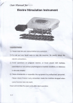
USEFI'S
MANUAL
All RishtsReseryed.
U.S.ZA)(CORPOR.HIION.
CopyrightO 1985,
PartNo. 20-l0l-00,Rev.A.
Frinted:June,1985
timitations on Warrantiesand ldabi[ty
ZAX Corpordion warrantsthis equipmentto be free from defectsin materialsand workmanshipfor a period
of one (l) year from the original shipmentdate from ZAX. This warranty is limited to the repaiiand replacement of parts and the necessarylabor and servicesreguired to repair this equipment,
During the l-year waranty period, ZAX will repair or replace, at its option,any defectiveeguipmentor parts
at no additional-charge,provided that the equipmentis ierumed, shipping prepaid, to ZAX. The purchaser
ls responslblet'orlnsudngany equipmentreturned, and assumesthe risk of loss during shipment.
Except as specified below,the ZAX Warrantycoversall defectsin materialsand workmanshipThe followrrg
are -99tcolered: Damage as a result of accident, misuse,abuse, or as a result of instatlaiion, operation,
modification, or service on the eguipment; damage resulting from failure to follow instructions cbntained
rnthe User! Manual;damageresultingfrom the performanceof repairs by someonenot authorizedby ZAX;
and any ZAX eguipmenton which the serial number has been defaced, modified,or removed.
Limihtion of Implied Warranties
AIJIJIMPLIEDWARRANTIES,
INC],UDINGWARRANTIESOF MERCHANTABIIJITY
AND FITNESSPOR
PARTICU],ARPURPOSE,
ARE LIMITEDIN DURATIONTO THE IJENCTHOF THISWARRANTY.
Exclusion of Certain Damages
IN NO EVENTWIIJLZAX BE I,IABI,ETO THE PURCHASEROR ANY USERFORANY DAMAGES.IN.
CI,UDINGANY INCIDEI\NALOR CONSEQUE}TIIA],
],OSTPRONTS,LOSTSAV.
DAMAGES,EXPENSES,
INGS,OR OTHERDAMAGESARISINGOUT OF THE USEOR INABILTTYTO USETHISEQUIPMEIVI.THIS
EXCEPIION INCLUDES DAMAGES THAT RESUIJTFROM ANY DEFECT IN THE SOTNNIENTON
MANUAIJ,EVEN IF THEY HAVEBEENADVISEDOF THE POSSIBILITY
OF SUCHDAMAGES.
SOME STAIESDO NOT AITLOWTHE EXCLUSIONOR LIMITATIONOF IMPLIED WARRAI{IIES OR
LIABILITYFORINCIDEI\MAI,ORCONSEQUE\IIIAI,DAMAGES,SOTHELIMITANONOREXCTUSION
MAY NOTAPPLYTO YOU.
THIS WARRAXTTY
GIVES)CIU SPECIFICIJEGAIJRIGHIs, AND YOUMAY ATISOI{AVE OTHERRIGHTS
WHICH VARYFROM STATETO STATE.
Disclaimer
Althoughevery effort has been made to make this User'sManualtechnicallyaccurate,ZAX assumesno
responsibiJityfor any errors, omissions,inconsistencies,or misprints within this document.
Copyright
This manualand the sofwaredescrilced in it are copyrighted with an rights reserved, No pafi of this manual
or the prognarnsmay be copied, in whole or in part, withoutwritten consentfrom ZAX, exceptin the normal use of sofrwareor to make a backup copy for use with the samesystem.This exception does not allow
copiesto be made for other persons.
ZAX Corpontion
Technical PublicationsDepartrnerrt
2572White Road
Irvine, California 92714
14{ i" " r.Si"tered trademark of ZAX Corporation.
IBfvIis a registeredtrademark of Intematio;al BusinessMachinescorporation.
PEC is a registeredtrademark of DigdtalEquipmentCorporation.
The BOXrefers to ZAX's8- and i&bit microtomputers,
Written by Mark D.Johnsonof ZAX Technical publications.
Changesgre periodically made to the informationherein; these changeswill be incorporatedin new
editiom of this publication.Updatesto this manualwill be sentto all manualrecipients.
A Reader'sCommentsform is provided at the back of this publication. If this form hasbeen removed,send
commentsto the address above.
ReorderUser'sManual20-101-00
ReorderCommandReferenceGuide 20-602{l
Gonlenls
xi
xii
xiii
ICD-278for 280 Features
SystemComponents
AboutThisManud
What This Manual WiIl ShowYou
Howto Use This Manual
Emulatoror ICD?
SECTIONI _ ICD DESCRIPTION& OPERATION
l-1
l-1
Introduction
A Word Of Caution
t-1
t-2
l-3
Getting Acquainted With Your ICD
A Few Features
The Controls and ComponentFunctionsOf YourICD
1-B
I€
l-8
l-9
l-t0
l-ll
I-12
How To ConnectYourICD To Other Devices
YourGoal: A Microprocessor DevelopmentSystem
YourSystem'sEnvironment
Hardware or Software?
Terminal or Host Computer Controlled?
ReviewingThe Operation Modes
SummingIt All Up , . .
t-13
SystemPreparation
r-13 Grounds
1-13
l-13
Power
Important FactsAbout The CPU In-Circuit Probe
I-t4
Using The ICD Without A Target System
(ferminal Controlled)
Using The ICD Without A Target System
fferminal C ontrolled/Host Storage)
Using The ICD Without A Target System
(HostComputerControlled)
Using The ICD With A Target System
(TerminalControlled)
Using The ICD With A TargretSystem
(TerminalControlled/Host Storage)
Using The ICD With A Target System
(HostComputer Controlled)
l-16
I-IB
r-20
r-22
r-24
lCD.278for Z8O
ZAXCorporolion
iii
t-26
r-26
What Can YouDo With Your MDS?
What To Do If YourMDS Is Not Working
I-27
l-27
I-27,
I-27
L-28
I-28
I-29
I-29
l-30
l-31
l-33
T?oubleShooting
Introduction:The Problem. . .
. . A n d T h eS o l u t i o n
What ShouldHappen
How To Get YourICD Working
CheckingElectricalConnections
DiagrnosingICD Interface Problems
ICD and External Cooling Fan
ICD and Terminal
ICD with TargetSystemConnected
What To Do If The ICD Still Doesn'tWork
I-34
l-34
l-35
l-36
l-38
More About l/icurICD
Introduction
AccessoryCables& Probes
Data Bus EmulationConnector
EmulationSelectSwitch
SECTION2 - IVIASTER
COMMAND GUIDE
2-T
ICD COMMANDS
2-2
Host & File Handling Commands
2-3
Introduction
2-4
ElementsWithin A Command.Statement
2-8
Example Of The CommandFormat
2-10 How To Enter A Command
2-I0 CommandExample
2-II
Entering The Example Command
z-LI What To Do If YouMake An lnput Error
2-12 Error Messages
2-13
2-15
2-16
2-17
2-lB
2-20
iv
ASSEMBLECommand
BREAKCommands
Stah-rs
Hardware Breakpoint Qualification
Hardware Breakpoint Specification
Eventthen Hardware Breakpoint
ZA)(Corporclion
ICD-278for Z8O
2-2r
2-23
2-25
2-26
2-27
2-29
2-30
2-32
2-33
2-34
2-36
2-37
2-38
2-39
2-40
2-41
2-42
2-43
2-45
2-47
2-48
2-49
2-59
2-60
2-6r
2-62
2-70
2-72
Z-IJ
2-73
2-74
2-76
2-76
2-77
2-80
2-8r
2-83
2-83
2-84
ICD-278for Z8O
ARM Initialize
SoftwareBreakpoint Specification
SoftwareBreakpoint Recogmition
Software/User Breakpoint Code
SoftwareBreakpointQualification
External SismalQualification
External Breakpoint Qualification
Event Breakpoint
Event Breakpoint Passcount
Write Protect Breakpoint
Timeout Breakpoint
COMPARECommand
Command
DISASSEMBLE
DUMP Command
EVENT Commands
Status
Qualification
Specification
EXAMINE Command
FIL,L,Command
GO Command
HISTORYCommands
Real-timeTrace Status
Real-timeTrace Counter Reset
Real-timeTrace FormatDisplay
Real-timeTrace StorageMode
Real-timeTrace Search
IDENTIFICATIONCommand
IN-CIRCUITCommands
Status
Specification
MAP Commands
Status
Specification
MOVE Command
NEXT Command
OFFSETCommands
Status
Specification
ZAXCorporolion
2-86
2-86
2-87
2-89
2-90
2-91
2-91
2-92
2-93
2-95
2-96
2-100
2-100
2-101
2-102
2-104
2-105
2-107
2-109
z-tll
2-II2
PIN Commands
Status
Specification
PORTCommand
PRiNTCommand
REGISTERCommands
Status
Reset
Examine& Change
SEARCHCommand
SUPERVISOR
Command
TRACECommands
Status
Qualification
Specification
USERCommand
LOAD Command
SAVECommand
VERIFYCommand
HOSTCommand
QUIT Command
2-ll3
CommandSyntaxSummary
SECTION3 _ TECHNICAI,REFERENCES
3-l
3-l
3-t
3-2
3-3
3-3
Introduction
Special Environments
Importantl
What Are The Five Control Modules?
3-4
3-4
3-4
3-4
3-7
3-8
3-8
Serial Interface Output Module
Description
Baud RateSwitches
Changing The Baud RateSettings
SIOS-791Module Components
How To Set The TtansmissionFormatSwitches
FactorySettings
Multiple ICDs
J-Y
YI
Indicator/Control Module
Description
ICD-278 for Z8O
3-t2
3-14
3-14
3-15
3-16
3-I7
3-17
3-tB
3-IB
3-19
3-19
Real-timeTrace Module
Description
3-20
3-20
3-21
3-2t
3-21
3-22
3-23
3-25
3-26
3-28
J-4Y
CPU ControlModule
Description
Internaland ExternalClock
How To Change The Internal Clock
ExternalClock
ICD/Target SystemInterface
CPU Timing
RESETSienal
INTERRUPTSisrnal
BUSControl
SettingDifferent Wait States
Sismal
REFRESH
3-32
3-32
3-33
3-34
3-35
EmulationMemory (Unit)Module
Description
ICD EmulationMemory
Target SystemMemory
Mapping
3-36
PowerSupply Specifications
3-37
3-37
3-37
3-38
3-40
3-42
3-43
3-44
How To DisassembleYourICD
Introduction
ImportantNoticeTo Users!
The Basic PartsOf YourICD
Procedure For DisassemblingThe ICD
How The Modules Are Connected
Procedure For RemovingThe Modules
InstallingThe Modules
J-ZY
lCD.278for Z8O
RS-232Interface
Current LroopInterface
Using The Current Loop Interface
TTI-,Interface
Using The TTL Interface
XON and XOFFProtocol
BUSYand DTRInput Signals
BUSYOUTand DSROutput Sigrnals
RSTPOutput Sigrnal
SECTTON4 _ COMMT'NICATIONPROTOCOL
vill
4-I
Introduction
4-2
4-3
4-4
4-6
4-7
4-9
4-13
4-16
4-18
4-19
4-20
4-21
REMOTEMode
Idle Progrram
CommandRequestProgram
FunctionAnalYsisProgrram
Text Display Progrram
Object File Load/Verify Progrram
Object File SaveProgrram
IlIegaI/"Z" CommandProgrram
Quit Progrram
ConsoleKey Check Progrram
Symbol/Numeral ConversionProgram
Symbolic Text Display Progrram
4-23
4-24
4-25
LOCAL,Mode
Idle Progrram
ConsoleCommand RequestProgrram
Request Program
4-27
Remote Command
4-29
4-30
4-34
4-38
4-40
4-4I
4-43
4-45
4-47
4-49
4-50
4-52
4-54
4-55
FunctionAnalYsisProgrram
Object File Load/Verify Progrram
Object File SaveProgrram
IlIega)./"Z" CommandProgrram
Quit Program
Symbol/Numeral ConversionProgram
Numeral ConversionProgrram
Symbolic Text Display Progrram
Command& Text ExecutionProgram
ConsoleCommand Input/Output Progrram
ConsoleCharacterReadProgram
ConsoleText Read Program
ConsoleCharacter Write Program
ConsoleText Write Progrram
4-57
4-58
Number ConversionCodes
SymbolConversionCodes
4-63
4-68
Intel Hex Object Format
S FormatObject File
ZAXCorporollon
IC.D-278for Z8O
A-l
Appendix A: Principles of Emulation
B-l
Appendix B: IGD Product Demonstration:
Features& Functionsof the ICD
C-l
Appendix C: Technical Specifications
D-l
Appendix D: TechnicalBulletins& Application Notes
Glossary
ICID-278for Z8O
ICD-278for ZEOFEATURES
flonspqrencV
. Supportsystemswith data bus buffer
o All memory available
o No conflist between emulation
. All I/O ports (256)available
. Dynamic RAM refresh
memory and user memory when
. DMA supported
overlaying
. Drive databus on emulationreads
User lnlerloce
. Youcontrol all functionsfrom computer or terminal
r Mnemonic command names
o Setupemulation controls from batch file on host computer
Emulqllon Conlrols
. Internal or external clock
. Disable interrupt inputs
. Disable bus reguest input
Memo4y Mqpplng
. IK mapping resolution
. Read-onlyemulation memory
Address qnd Dqfo
Speclficollons
. Four offset registers
. One bit "don't care" resolution
Breokpolnls
Ttoce
Non.Reql.Tlme
Reql.Tlmelfqce
r "No memory" specification
o Controlfrom keyboard
. Break on opcode fetch only
. Break on intemrpt acknowledge
. Break on Nth occurrence
o Break on wait statetimeout
. External break input (triggers from
HI or LO edge)
o Extemal break outout
o Unlimitedbreakpointson address
. Four hardware breakpoints
. Eight software breakpoints
o Break on a specified address
or data
. Break on range
r Break on accessto non-memory
area
r Break on write to read-onlyarea
r Seguentialbreak (A then B)
. Single step
. Step n steps
. T?acejumps only
o Storesaddresses,data, and status
.2Kx32 bits trace memorysize
. Ttace control modes include:
BeginMonitor
End Monitor
BegrinEvent
End Event
Center Event
Multiple Event
. Adjustable delay
Dlsossembly Cqpobllltles
Speclql Feolures
ICD-278for Z8O
r Disassemble from progEam memory
. Disassemble Eace memory from any selected area
e Assemble into memory
. Use ICD's serial interface frpm
user prognam
. Search progrram memry for pattern
. Search Eace memory for pattern
ZAXCorporotion
xi
s-ssN-^s
SH
Dqlq Bus Emulcillon
Conneclorond feslCtlp
Emulafioneuqffy/
Eventlllgger Probes
ZAXCorporolion
ICD-278for Z8O
Abouf Thls Mqnuol
Thank you for choosing aZAX in-circuit emulator! Your ZAX
emulator is one of the most powerful and sophisticated microprocessordevelopmenttoolsin the industry-as you will soon
discover,But for all the things your emulator can do, it's still
very simple to use.In fact, you don't haveto know a thing about
ZAX emulatorsto use this manual,The informationpresented
in this manual is struchrred for first-time users, so you'll be
learning about emulation techniques and applications as well.
if you're already familiar with the principles of emulation,you
can use this manual to learn a few basic emulator skills, and
then use the section on commandsas a reference.
WhqtThls Mqnuql
Wlll Show You
r How to identify the parts (controls,componentsand accessories)of your emulator and what they do (Sectionl).
r How to connectthe emulatorto your terminal, host computer and target sYstem(Sectionl).
r How to find out more about special emulator controls and
learn how to use them for your specific applications(Section l).
r How to use the accessoriesthat came with your emulator
(SectionI).
r How to use each of the emulator commands(Section2).
r How to learn more about how your emulator works by examining the internal control modules (Section3).
r How to write support software progEamsfor communication
between the emulator and a host computer (Section4).
How To Use Thls Monuql
lCD.278for Z8O
There are really only two things you must know to use a ZAX
emulator;the first is how to connect it to your present system,
and the second is how to control the emulator'soperation by
using the commands.Thesetwo subjectsare presentedin the
first two sectionsof this manual,and of these t!vo,you'll be using the sectionon "commands"particularly.
xiii
Sofirst, read SectionI to learn about the variouscontrols and
componentsof your emulator,(Before you can operate your
emulator,you'll have to set certain switches and make some
minor adjusbnentsso that it performs correctly with your system,)Then, continueon to learn how to connectyour emulator
to other devices, such as a console terminal or a host computer, and your target sYstem.
Once your emulator is working properly, you can refer directIy to Section2 to find out how to enter any of the emulatorcommands,Each command'sfunction is examined alongwith the
formatneeded to use the command.Once you're familiar with
the commandsyntax,you can use the fold-outCommandRel
erence Guide Iocated in the front of the manual.
If you need a refresher course on emulation principles, turn to
Appendix A. If you're not sure how to apply the commandsin
an actual emulationsession(we call it "debugging"), turn to
Appendix B for a demonstation.Use Section3 for a reference
(it containstechnicalinformationthat you may find usefullater
on).You can use Section4 if you're writing your own support
software progrramsto interface your host computer to the
emulator.
Oh by the way,any time a word or phrase is used and you dont
understandits meaning,turn to the Glossaryat the back of this
manual. It contains definitions for a number of common
engineering terms as well as many specialized microprogrramming terms,
Emuloloror ICD?
One last thing-the official name of your emulator is the
ICD-278for 2800CD standsfor IN-CIRCUITDEBUGGER;278
is the model number), That's quite a mouthful though, so to
shortenthings up we'll use the initials ICD whenever we mean
the ICD-278, in-circuit debugger, emulator, or in-circuit
emulator.
Now turn to Section I and get started.
xiv
ZA)(Corporollon
ICD-278for Z8O
Cooling
Fqn
AC PowerCord
Dqlq Bus Emulqtion
Connecfor qnd Test Clip
l:
/A
i#,
Emulolioneuolify/
Evenllligger Probes
CPU In-circuif Probe
Mop Control/Exfernql
Breok Probes
ZAXCorporoiion
ICD-278for Z8O
& OPERATION
ICD DESCRIPIION
SeclionI
Conlenls
SECTIONI _ tCD DESCRIPTION& OPERATION
I-1
I-t
Introduction
AWord Of Caution
l-t
l-3
Getting Acquainted With Your ICD
A Few Features
The Controls and ComponentFunctionsOf YourICD
1-8
1-8
1-B
1-9
1-10
I-1I
I.T2
How To ConnectYourICD To Other Devices
YourGoal:A MicroprocessorDevelopmentSystem
YourSystem'sEnvironment
Hardware or Software?
Terminalor HostComputerControlled?
ReviewingThe Operation Modes
SummingIt All Up . . ,
t-13
l-13
t-13
I-13
SystemPreparation
Grounds
Power
Important FactsAbout The CPU In-Circuit Probe
T-14
Using The ICD Without A Target System
(TerminalControlled)
Using The ICD Without A Target System
(TerminalControlled/Host Storagre)
Using The ICD Without A Target System
(HostComputerControlled)
Using The ICD With A Target System
(TerminalControlled)
Using The ICD Wtth A TareletSystem
fferminal Controlled/Host Storage)
Using The ICD With A Target System
(HostComputer Controlled)
r-2
l-16
l-18
I-20
t-22
t-24
r-26 What Can YouDo With YourMDS?
r-26 What To Do If YourMDS Is Not Working
I-27
Trouble Shooting
r-27 Introduction:TheProblem, , .
r-27 , , , And The Solution
L-27
ICD-278for Z8O
What ShouldHappen
zAx
l-A
& OPERATTON
le9 DESCRTPTTON
l-28
I-28
l-29
I-29
l-30
1-31
l-33
Seclion I
How To Get YourICD Working
CheckingElectricalConnections
DiagmosinqICD Interface Problems
ICD and ExternalCoolingFan
ICD and Terminal
ICD with Target SystemConnected
What To Do If The ICD Still Doesn'tWork
1-34 More About YourICD
1-34 Introduction
l-35 AccessoryCables& Probes
1-36 DataBusEmulationConnector
1-38 EmulationSelectSwitch
l-B
ZAXCorporolion
ICD-278for Z8O
& OPERATION
ICD DESCRIPTION
SectionI
lnhoducllon
In Section1 you'll learn aboutthe differentparts of your ICD,
what they do, and how to use them, You'll alsolearn how to
connectthe ICD to your system(terminal,host computer,target system),and find out abouthowto use the accessoriesthat
come with the ICD. Your ICD has a few special features that
you should know about, too; you can find information about
these featuresin this section as well.
AWord olCqullon
lbu shouldn't try to attach the ICD to any external device
before you finish reading this section.As long as the power
cord is disconnected you can't hurt anything internally, but
don't connect the ICD to your target systembefore you read,
"How to Connect Your ICD to Other Devices."Although it's
difficult, it is possb/e to get the cables to the target system
reversed, which could result in damage to the ICD's internal
components.
Gelllng Acquolnted
lUlth Your ICD
Your ZAX lCD-series in-circuit emulator is a microprocessor
emulationdevice that can be used for developing and maintaining microprocessor-basedsystems.It does this by letting
you direct and test activities in your prototype ("target")
system. You perform these operations by entering one or
more debugger commands.
All ZAX lCD-series emulators are controlled by a separate
terminal or in conjunctionwith your existing host computer
system.Youcan use the debugger commandsfor your hardware or software projects by simply inputting the command
mnemonicsand parameters from just about any terminal or
popular computer you might own.
ICID-278for Z8O
ICD DESCRIPTION
& OPERATION
A FewFeolures
SectionI
Here are just a few things you can do using the debugger
commands:
r Use the ICD's emulation memory to simulate or take the
place of memory (or future memory) in your target system,
I Use a single-step trace operation to move through your program, one step at a time, and examine the reqister's contents after each step.
r Set a combination of hardware and software breakpoints to
stop your progrramwhen: data is written or read into a
specific address, an event point is passed, a non-existent
memory access is attempted, or an interrupt is acknowledged by the CPU,Hardware breakpoints can also generate triggers for instruments such as logic analyzers and
oscilloscopes.
I Record ("trace") a portion of your prognam(beginningrand
ending anywhere within the prognam)and store it in the
ICD's real-timetrace buffer without affectingthe emulation
process.Later you can display the recorded memory contentsin either machine code or in its disassembledformat.
r Translate symbolic codes into machine instructions,item
for item, using the in-line assembler.
r Selectivelyenable and disable the intemrpt or bus request
inputs-including non-maskableinterrupts.
You can turn to Section2 for a complete list of the ICD,s debugger commands.To find out about other things your ICD
can do, turn to "More About YourICD"
Now turn the page to learn about the parts of your ICD.
l-2
ICID-278for Z8O
& OPERATION
ICD DESCRIPTION
SectionI
The Conlrols And
Gomponent Funcllons
OlYour ICD
o
AC Power Select Switch. This switch is used to select the
power requirementsfor the ICD.Setthe switchto ll0V/I17V to
run on a power supply of I I0-I20VAC, or select 200V/240Y to
run on a power suPPIYof 200-240.
@
AC POWER CORD Receptacle.Accepts female end of the
supplied three-wire power cord. Be sure to disconnect the
power cord before movinqthe ICD'
o
DC FAN Receptacle.Accepts connector end of the 24V DC
fan,
ilililllillllllllllllilllilillllllll
ilillllllllll
aClD-278lotZ8O
ZAX Corporotion
ICD DESCRIPTION
& OPERATION
o
@
o
o
@
o
l'4
Seclion I
TERJVIINAIPort Connector. Accepts male end of an RS-232
cable to attachthe ICD to a terminal in a stand-alone(l_.,OCAt
mode) configmration.When using the ICD in the REMOTE
mode, this port can be used as an auxiliary I/O.
HOST/AIIXPort Connector. Accepts male end of an RS_232
cable to attach the ICD to a host computer systemwhen the
ICD is operating in the REMOTEmode. ICD commandscan
then be entered using the computer'skeyboard. When using
the ICD in a stand-alone(LOCAL mode) configruration,this pofi
dumps object code,reedsters,
or memoryto a hostcomput& or
printer,
TOCAL/REM (local/Remote) Select Switch. This switch is
used to selecrwhich port (IERMINAL or HOST/AUX)the ICD
will use to receive commands.
BATDRATE Switches (TERMINAL and HOST/AIIJe. These
switchesare used to set the baud rates for the TEnvIivRl-, ana
HOST/AUX ports. The factory setting is +t-g600 bps, To
changethe baud ratesof the ICD see ,,TechnicalReferences".
SIOmodule
DCE/DTE SelectSwitch.This switch is used to set the HOST/
AUX pofi to either RS-232data terminal equipment (DTE)or
data communicationsequipment(DCf1. Use the DTE settingif
the ICD is used with a hostcomputer.Use the DCE settingii a
printer is connected to the HOST/AUXport. (The TERMINAL
port is alwaysDCE.)
DB. EMItt @ata Bus Emulation) Connector. Accepts female
end of the DataBusEmulationCable.(See,,MoreAbout your
ICD" for details on how to use this cable.)
@
Top In-circuit Probe Receptacle.Accepts female end of the
Top In-circuitProbe.
@
BottomIn-circuit Probe Recepacle. Accepts female end of the
BofiomIn-circuit Probe,
ZAX Corporolion
IclD-278 for Z8O
& OPERATION
ICD DESCRIPTION
Seclion I
@
E.M. SEt (EmulationSelect)Switch.This switch is used to set
the machine cycle operationto the targretsystem.(See"More
About YourICD" for detailson what this switchdoes,)
@
EXL BRK.(ExternalBreak)Connector.Acceptsfemale end of
the External Break/Map Control cable, (See "More About
YourICD" for detailsabouthow to use this cable.)
@
EVENTTRG.@ventTriqger) Connector.Accepts female end
of the Event Trigger/Emulation Qualify Cable. (See "More
About lbur ICD" for detailsabouthow to use this cable.)
REM
(C --
--I---I
--
BAUDRAIE-
oIE
-r---@
-r---
--IrI-
------I
-----r--I--!r-
lCD.278lot 280
ZAXCorporotion
ICD DESCRIPTION
& OPERATION
1.6
SectionI
@
POWER ON/OFF SWITCH. This switch is used to supply
power to the ICD.
@
CLOCKINT/EXI SWTTCH.This switchis used to selecteither
the ICD's internal clock (lNT) or the target system'sclock
(EXT:external),
@
HAIT tamp. This I-.,EDcomes on after the ICD's CPU has
instructionorwhen a BUSAK(BUS
stopped executinga HEI-.,P
progrress.
is in
ACKNOWIJEDGE)
@
RESHISwitch.This switch is used to reset the ICD monitor.You
can push it any time the MONITOR lamp is lit' After you push
the RESETswitch,you'llsee the ICD's identificationmessage
on your terminal'smonitor.
@
MONITORlamp. This L,EDcomeson to indicatethat control is
currently in the ICD's monitor. It will not be lit during
emulation,
@
ICE (In-Circuit Enable) Lamp. This I-.,EDcomes on when the
ICD is operatingin the in-circuitmode II or 12.
@
MONITORBreak Switch.This switch is used to return control
to the ICD monitor during emulation.
@
POWERlramp. This L,EDcomes on to indicate that power is
being supplied to the ICD.
ZAX Corporotion
IC.D-278for Z8O
& OPERATION
ICD DESCRIPTION
Seclion I
-
-
I
-
I
I
I
I
I
I
-
I
I
I
I
I
I
I
I
I
I
-
I
I
-
-
II
I
I
I
I
I
I
-
-
-
-
-
-t
E
DEBUGGER
IN.CIRCUIT
278
EMULATABLE
UPTO6MHz
Now turn to the next chapter to learn how to connect your ICD
to your slrstem.
ICID-278for Z8O
ZAXGorporolion
ICD DESCRIPTION
& OPERATION
Secllon I
Howlo Gonnecl
YourICDTo
Olher Devices
YourGoql:A
In the main introductionyou read that properly connectingthe
Mlcroprocessor ICD to your systemwas one of the most important thingrsyou
DevelopmentSyslem would Iearn in this manual.The following informationwill show
you how to connectthe ICD's components,what cables to connect and where they go, and which switchesare set to what
positions.Once you havecompletedthe proceduresoutlined
in this chapter,you'll havewhat is called a "Microprocessor
DevelopmentSystem"(MDS),By using the commandsand
applicationsfound in Section2, you'll be able to perform a
remarkable variety of debugging operationswith your MDS.
YourSystent's Beforeyou connectyour ICD to anythtng,you'll need to answer
Envlronmenl lhree .ouestionsabout your system's-environment.First, will
Second,will you control the systemwith a terminal or a host
computer? And third, if a terminal is used to control the ICD
will a host computer be used as a source for data files?
l-8
ZAX Corporolion
lClD.278for Z8O
SectionI
Hordwqre or Soflwqre?
& OPERATION
ICD DESCRIPTION
Your hardware is called a "target system."By physically removingthe CPU in your systemand electronicallyreplacing it
with the ICD's internal microprocessor,you can control, test,
and check almostall possible functionsin your target system,
If this is the mode you'll be operating in, look at the three system confignrrationsin USING THE ICD WITH A TARGET
SYSTEM.
Can you use your ICD without a target system?Of coursel
Whenever you develop and debug softwareyou'll be doingrit
without the use of a target system,This mode is also an effective way to demonstratesome of your ICD's features.If this is
the mode you'll be operating in, look at the three systemconfisnrrationsin USINGTHE ICD WITHOITTA TARGEI STSfEM.
(n fact, if thisis the first time you are using a ZA)( emulator,you
shouldconstrucf t/rrEntem configwation and then turn to Appendix B at the back of the manual. There you will find a
demonstration of the functions and featuresof your ICD,)
ICD-278for Z8O
ZAX Gorporolion
ICD DESCRIPTION
& OPERATION
lermlnol or Hosl
Compufer Gonhoiled?
Seclion I
If you'll be controllingthe ICD by a consoleterminal,it's called
TERMINAI CONIROT OF THE ICD. In this mode, the ICD
"standsalone" (rence the name,stand-aloneemulator)or apafi
from the auxiliary control of a hostcomputer system.The ICD
assumesa stand-alonemode of operationwhen you place the
ITOCAL/REMswitch to the IJOC(LOCALT)
position.
tNlrlllllI ililililrg
ilililil 11
i@nnr
ltujilill ililllllll!]
[ltl
l=Hl
tEl
IEIIul
UU
coMMANps |
I coMRoLLtNG
a0i
i[!
|
oproNnl pnlrurEn
I
If you'll be controllingrtheICD with a hostcomputer and using
the utility software program ZICE, it's called HOST COMPIITERCONTROTOFTHE ICD. The ICD assumesthismode
of operation when you place the I-TOCAL/REMswitch to the
REM(REMOTE)position.
OPIIONAIPRIMER
l-lO
ZAX Corporolion
lCD.278 for Z8O
Seclion I
& OPERATION
ICD DESCRIPTION
Finally,you may chooseto control the ICD with a terminal and
use a separatehost computer to store data files, or connect a
printer to the host computer to dump data for hard copies.This
mode of operation is called TERMINAT CONTROI OF THE
ICD (WITH HOST DA|IA FITES),In this mode, the ICD is still
under direct control of the terminal while the host computer
seryesas a data storagedevice.Youcan alsocausethe ICD to
assumea "transparent" condition, which allows direct communicationbetween the terminal and host computer.
o
o
[l|milmr[[[[-----l
rgt
NOTE:ZICE software may be used in the LOCAL mode: Terminal Control Of TheICD ]ililh HostData Files),for accessing
theZICEcommands(help files,"2" commands,etc),?b useths
LOCAL "host computer assrsfed"mode, see /ie HOSTcommand in Section2,
ICD-278for Z8O
& OPERATTON
lqD DESCRTPTTON
Revlewlng The
Operollon Modes
SectionI
Nowlet's review the six different operationmodesof your ICD.
USINGTHE ICD WITHOW
A TARGETSYSTEM
USINGTHE ICD WITH
A TARGETSYSTEM
I Terminal Control of the
ICD-L,OCAI-,mode of
operation
I Terminal Control of the
ICD-LOCAI-,mode of
operation
I Terminal Control of the
I Terminal Control of the
ICD (With Host Data Files) ICD (With Host Data Files)
-LOCAL mode of
-L,OCAL mode of
operation
operation
I Host Computer Control of I Host Computer Control of
the ICD-REMOTE mode
the ICD-REMOTE mode
of operation
of operation
Summlng ltAll Up...
r YourICD can functionin any of six differentmodes.
I YourICD can be used to debug hardware or software.
r YourICD can operate with or without a target system.
r YourICD can dump data directly to a printer.
r YourICD can dump data to a printer attached to a host computer,
r YourICD can be controlled by just a terminal or by a host
computer.
r Your ICD can be controlled by a terminal and then use a
separate host computer for storinq data files or outputting
data to a printer.
r YourICD can be controlledby a terminal and then use a
separatehostcomputerfor accessingthe ZICE commands.
Now turn the page and read about preparing a site for your
system.
l.l2
ZAX Corporotion
ICD-278for Z8O
& OPERATION
ICD DESCRIPTION
SectionI
SysilemPreporollon
Grounds
Reqd Thls BeforeYou Connect Anythlng!
YourICD is eguipped with a three-wire polarized receptacle
that acceptsa three-wire cord. This cord connectsto a power
source and protective grround.Make sure that you plug the
polver cord into a properly grroundedlI5 VAC receptacle.Do
not try to bypassthe three-prong plug wth an adaptor (3-into
2-prongadaptor).
THE GROI'ND TERMINAL OF THE PLUGIS USEDTO PRE.
VENT SHOCKHAZARDS-DO NOT BYPA$StT!
Power
Your ICD is normally set to operate on a voltage supply of
ll0-120VAC but this can be changedto 200-240
VACby setting
the PowerSelect Switchto the 20AV/240Vposition,
In mostcases,a multiple power outlet strip should be used to
provide voltageto the entire system(hostcomputer,terminal,
pdnter, target system),Most power outlet strips are equipped
with a circuit breaker in case of an overload, and all are
properly gnounded.
No matter what type of power source you use,alwaW apply
power after connecting the ICD to an electrical outlet, and
always apply power in the same sequence: switch on the
power supply first, and then press the POWER-ONswitch.
lmporfonl Fqcts Aboul The
GPUIn'Clrcull Probe
The CPU In-circuitProbe is used to connectthe ICD to your
target system.The probe consistsof a 2O-inchribbon cable
with three end connedors. The 40-pin connector end of the
probe plugs intothe targetsystem'smicroprocessorsocket.On
the other end of the probe are two socketswhich plug into the
ICD's In-circuitProbe receptacles.The socketsare labeled
TOP and BOTIOM and MU$I be placed in the corresponding
topp and bottomreceptacles.
CAUTION:DO NOT REVERSEPROBECONNECTIONS.MI$
MATCHING THE TOP AI'IIDBOTTOM SOCKET CONNECTA.RSJFJI,f_trIISF
QEI'EDE
r\trll,?rr.tl
rrtt-r .tlr'E
r.rn
rrrn
Now turn to the appropriate heading on the next few pages to
constnrct Jrour microprocessor development s]tstem.
ICD-278for Z8O
zAx
l-13
ICD DESCRIPTION
& OPERATION
Secllon I
USING THEICD WITHOUTA TARCETSYSTEM
(TERMTNAT
CONTROTTED)
SystemConllgurollon:Termlnqlconhol of lhe ICD
Opercllon Mode: tOCAt
Fqcllltlesneededlor lhls syslemcontlgulollon:lCD,ConsoleTermlnol,
(l) RS.232coble.
To use the ICD in this mode, constructthe systemconfignrrationshorm on the oppositepage
usinq the informationbelow.
First . . .
Make sure that the power to the ICD and all externally attacheddevices (terminal,prmter) is
OFF,then proceed as follows:
l) Attach the COOLING FAN to the ICD and then plug the fan's connectorto the receptacle
labeled DC FAN POWER.
2) Connectyour terminal to the ICD by using an RS-232cable.Attach the cable from your terport to the ICD's TERMINALport connector.The ICD defaultsto
minal'sserial (EIA RS-232)
9600baud, 8 data bits, 2 stopbits and no parity: set up your terminal to thesespecifications.
3 ) (Optional)Connectyour printer to the ICD by using an R$232cable. Attach the cable from
your printer to the ICD's HOST/AUX port connector.
4 ) Plugthe AC POWERCORDintothe ICD's power receptacleand thenconnectthe otherend
of the cable to a power source.
Now SetThis:
400v/4riTv 200vt240v
LOCAUREM
INT/EXT
DCE/DTE
Boud Roles
POWER
ON/OFFSwiich
To This:
ltiovltiriTv
LOCAL
INT
DCE
To change theICD'sbaud
9600 bps Q,trOTE:
rate,s,see the chart on the oppositepage.)
ON
The following messageshould now appear on your monitor'sscreen (you may have to press the
ICD-278for 280
V2.O
Now turn to page l-26.
l.l4 ZAX Corporolion
ICO-278for Z8O
& OPERATION
ICD DESCRIPTION
Seclion I
@
@
o
termlnol's EIA RS.232Poil
porf
ICDPSTERMIilAL
Use chorf below lo chonge bqud rqle l,orlGDs IERMINAI pott
)v
--
Boud Role Switch No.
Boud Rote [bps)
ICD-278for Z8O
tl12
?
6
7 8
4
0
1.4N . 2 1600 ann ,t50 a t
49.21 ) . 6 K 4 . 8 2
--
9
A
B c D
4 , t 0,t34.5200 , l , 8 K 2K
E
F
ZAX Corporolion l-15
& OPERATTON
lcD DESCRfPTfON
SectionI
USINETHEICDWITHOUT
A TARGET
EYSTEM
(TERM|
NAr CoNTROttE
D/HOSTSTORAOE)
syslem-co{lgurotlon: Termlnolconhol olthe tcD (wlth hosfdotc files)
OperolionMode:tOCAt
Foclllllesneededlor thls syslemconflgurollon:tcD, console Termlnol,
HostGomputer,(2) RS.232cqbtes.
To use the ICD in this mode, constructthe systemconfignrrationshownon the oppositepage
using the informationbelow,
First. . .
Make sure that the power to the ICD and all externally attacheddevices (terminal, printer, host
computer) is OFF, then proceed as follows:
l) Attach the COOLING FAN to the ICD and then plug the fan's connectorto the receptacle
labeled DC FANPOWER,
2) Connectyour terminalto the ICD by using an RS-232cable. Attach the cable from your terIllal's serial @IA R$232)port to ttrbICO;sTERMINALpoTtconnector.The ICD defaultsto
9600baud, 8 data bits, 2 stdpbits and no parity: set up your terminal to thesespecifications.
3) Connect your hostcomputer to the ICD by using an R9232cable. Attach the cable from your
hostcomputer'sserial (EIA RS-232)
portio thelcD's HOST/AUX port connector.
4) Plugthe AC POWERCORDintothe ICD's power receptacleand thenconnestthe otherend
of the cable to a power source,
Now SetThis:
,r00v/,f
17v200vt240v
LOCAUREM
INT/EXIDCE/DTE
Boud Rotes
POWER
ON/OFFSwitch
To This;
lllvltiti7v
LOCAL
INT
DTEif you're using ZAX's BOX microcomputer, DCEfor other personal computers,
9600 bps (NOTE:To change the ICD's baud
rates, ,seethe chart on the oppositepage.)
ON
Jle_laUowingmessageshould now appear on your monitor'sscreen (you may have to press the
RESETswitch on the ICD)r
ICD-278for 280 V2.O
Now turn to page 1-26,
aCD-2781or28O
& OPERATION
ICD DESCRIPTION
Secllon I
@
@
o
o
o
Iermlnql's EIARS-232porl
IGEIsIERMINALporl
lCDs HOSI/AUX porl
Gompule/s SIO porl
Use chqd below lo chqnge bqud lqles lor ICD'sTERMINAIqnd HOSI/AUX porls
HOSTSTORAGE
IERMINAL
Boud Rote SwitchNo.
Bqud Rote(bps)
ICD-278for Z8O
ti
1
x
9
A
6 7
B
z
4
D
0
,l5c
,
1
,
t
0
4
a
L
,-.4N
/o
434,5200 r . 8 K2K
.21 600 t00
19.2N7.6N
E
ZAX Gorporolion
F
ICD DESCRIPTION
& OPERATION
Seclion I
USINO THEICD WITHOUTA TAROETSYSTEM
(HOSTCOMPUTERCONTROTTED)
QVsfemConflgurotlon:Hostcompuler conlrol of the ICD
OperqlionMode:REMOTE
Focllltlesneeded lor thls syslemconftgurcilon:lCD,HosfGompuler,
ZICEsoflwore,0)RS.232cqble.
To use the ICD in this mode, constructthe systemconfign:rationshornrn
on the oppositepagre
using the informationbelow.
First. . .
Make sure that the power to the ICD and all externally attached devices (host computer,
printer) is OFF,then proceed as follows:
l) Attach the COOLING FAN to the ICD and then plug the fan's connectorto the receptacle
labeled DC FAN POWER.
2 ) Connect your hostcomputer to the ICD by using an RS-232cable. Attach the cable from your
hostcomputer'sserial(EIA RS-232)
port to thelCD's HOST/AUXport.
3 ) Plugthe AC POWERCORDintothe ICD's power receptacleand thenconnectthe otherend
of the cable to a power source.
,f00v/,t 17v 200vt240v
LOCAUREM
INT/E}O
DCE/DTE
Baud Rates
POWER
ON/OFFSwitch
140V1417V
REM
INT
DTEif you're using ZAX'sBOX microcomputer; DCEfor other personalcomputers.
rafet ,see the chafi on the opposite page.)
At this point,you will haveto load the ZICEsoftwareprogramnecessaryfor interfacinqthe ICD
to your hostcomputer.Executethe program loading commandsas outlined in the ZICE software
documentation.
The following messageshould now appear on your monitor'sscreen (you may have to press the
RESETswitch on the ICD):
ICD-278for 280
V2.O
Now turn to page I-26.
l-18 zAx
lCD.278for Z8O
& OPERATION
ICD DESCRIPTION
SectionI
o
o
@
lCDb HOSI/AUX port
Host compulefs StO Porl
Usechqrf b€low lo chonge bqud rqte for lCDs Host/AUX port
HOSTCOMPUTER
:
,:\f-ll
---
Boud Rote Swilch No.
Boud Rote[bps)
/,CD-278for Z8O
-l
F"a
6
7
4
41213
0
4En
A
A
I
4
.
2
1
300
500
2,41
19.2N).6t
A
B (^ D
4 1 0134,520c,,|.8K2K
9
AE
L!
E
F
SectionI
lCD DESCRIPTION
& OPERATION
(TERMINAL
CONTROTTED)
uslNG THErCDW|THA TARCETSYSTEM
SystemGonfigurollon:Termlnolconlrol of the IGD
OperotlonMode: tOCAt
Fqcllltlesneededfor thls systemconllgurollon:lCD,Consolefermlnol,
TorgelSyslem,CPUIn-clrcullProbe,0)RS-232coble.
To use the ICD in this mode, constructthe systemconfign:rationshorrn on the oppositepage
usinq the informationbelow.
First. . .
Make sure that the power to the ICD and all extemally attacheddevices (terminal,printer,
target system)is OFF,then proceed as follows:
1) Attach the COOLING FAN to the ICD and then plug the fan's connectorto the receptacle
labeled DC FAN POWER.
2) Connectyour terminalto the ICD by using an RS-232cable. Attachthe cable from your terminal'sserial (EIA R$.232)port to the ICD's TERMINALpoTtconnector.The ICD defaultsto
9600baud, 8 data bits, 2 stopbits and no parity: set up your terminalto thesespecifications,
3) (Optional)Connectyour printer to the ICD by using an RS-232cable. Attachthe cable from
your terminal to the ICD's HOST/AUX port connector.
4) Removethe existing(280)CPUfrom your target systemand insertthe IN-CIRCUITPROBE
(40-pinend) socket into the target system'sCPU socket(pin I of the ICD's In-circuit probe
socket goes into pin I of the target system'sCPU socket).Connect the other end of the
IN-CIRCUITPROBEto the ICD's TOP and BOTIOM In-circuitProbe Receptacles.THE
LONGESTCABLE MUST BE CONNECTEDTO THE TOP IN-CIRCUITPROBE
RECEPTACLE.
5 ) Plug the AC POWERCORDinto the ICD's power receptacle,then connectthe other end of
the cable to the samepower sourcethat is used by your target system.
Now Set This:
,100v/417v200vt240v
LOCAL/REM
tNT/ilCt
DCE/DTE
Boud Rofes
POWER
ON/OFFSwitch
To This:
440V1447V
LOCAL
EXT
DCE
Tochangethe ICD'sbaud
9600 bps Q,{OTE:
rafes, see the chart on the oppositepage.)
ON
The following message should now appear on your monitor's screen (you may have to press the
RESET switch on the ICD):
ICD-27E
for260 V2,0
Nowturnto page1-26.
l.2O ZAX Corporolion
for Z8O
aC.D-278
& OPERATION
ICD DESCRIPTION
SectionI
6
@
o
o
€
lermlnql's EIA RS'232Poil
ICD'SIERMINAI port
lCDb ln.clreult Probe leceplqcle
lqrget systerds CPUsockef
Use chqrl bolow fo chqnge boud rolE for ICD'STERMINALPort
lo
-
e
IAROETSVS|EM
unore'u'iftfiffi I l'J'j 'j'J'J':
oo
ffiH[
[-r'
ffiilUfi,nn
mEE
sfifltr*"ililnmffI
t
Bqud Rqle Switch No.
Boud Rote(bPs)
ICD-278tor Z8O
7 A
A
B l^
D
6
4
t
5
1
.
8
K
2K
,2N 5 0 0 1 3 0 0 1 4 5 04 , 1 034.€ 20c
19'21).6K14.8K12,4N
0
l
213
t
F
ICD DESCRIPTION
& OPERATION
Seclion I
USINGTHEICDWITHA TARGET
SYSTEM
(TERM|NAT
coNTROtTED/HOST
STORAOE)
syslem.colflsyrolton: Termtnclconhol otthe tcD (wilh hosldofofites)
OperolionMode: tOCAt
Foclllllesneededfor lhts syslemconflgurollon:lc4 consote rermino!,
Hostcompuler, Torgetsysiem,cpu trilclrcuttprobd,(2) Rs-232cobb6.
To use the ICD in this mode, constructthe systemconfignrrationshownon the oppositepage
using the informationbelow.
First. . .
Make surethatthe power to the ICD and all externallyattacheddevices(terminal,printer, host
computer,target system)is OFF,then proceed as follows:
l) Attach the COOLING FAN to the ICD and then plugrthe fan's connectorto the receptacle
labeled DC FAN POWER.
2) Connectyour terminal to the ICD by using an RS-232cable. Attach the cable from your terminal'sserial (EIA R$232)port to thb tODis TERMINALpoTtconnector.The ICD defaultsto
9600baud, 8 databits, 2 stopbits and no parity: set up your terminal to thesespecifications.
3) Connectyour terminalto the ICD by using an RS-232cable. Attach the cable from your hosr
computer'sserial (EIA Rs-232)port to the ICD's Hosr/AUX port connector.
4) Rgmgvethe existing(280)CPU from your target systemand inserrthe IN-CIRCUITPROBE
(40-pi1end) into the target system'sCPU socketlpin t of tne ICD's In-circuit probe socket
goe_s
into pin I of the target system'sCPU socket).Connectthe other end of the IN-CIRCUIT
PROBEto the ICD's TOP and BOTTOM In-circuit Probe Receptacles.THE LONGEST
. CABLEMUSTBE CONNECTEDTO THE TOPIN-CIRCUITPROI'ERECEPTACLE.
5 ) Plus the AC POWERCORDinto the ICD's power receptacle,then connectthe other end of
the cable to the samepower sourcethat ijused by th6 target system,
Now SetThis:
,100v/417V200Vt240v
LOCAUREM
INT/Dfl
DCE/DTE
Boud Rotes
POWER
ON/OFFSwitch
To This:
puteri DCE for other personal computers.
rates, ,see the charl on the opposite page.)
messaugr]rguldnow appear on your monitor'sscreen(youmay haveto pressthe
Ilgl*o*inq
RESETswitch on the ICD):
ICD-278torZSO V2.0
Now turh to pase l-26.
l-22 ZAX
lCD.278for Z8O
& OPERATION
ICD DESCRIPTION
SectionI
o
@
o
o
e
(E
@
lermlnolb EIARS.232poil
ICEPsTERMINALporl
IGD's HOS'|/AUX port
ComputePs SIO porf
ICD'sln.clrcult probe recepfqcle
Iorget sryslert'sCPUsocket
Usechqd below lo chonge bqud rqles lor ICD'sIERMINALqnd HOST/AUXports
HOSTSTORAOE
TARGEISYSTEM
unofir 'uilfi ffi l l l l i l i l
--,
ffigpffi
,,-=E
=-F
ilililrl
ffinn trl ffi-f
sltrffi*'o'ffi
Boud Role Swilch No,
Boud Rqte (bps)
lClD.278for Z8O
0
1
2
3
4
.21 600 300
49,2N ).6K14.8K12.41
7
I
6
A
B c D
,150 75 4 4 0134.5)nl 1 . 8 K2K
E
ZAX Corporolion
F
& oPERAT|ON
lcD DESCRtpTtoN
Seclion I
USING THEICD WITH A TARGETSYSTEM
(HOSTCOMPUTERCONTROTTED)
Sys'lemConflgurollon:Hostcompuferconlrol of the ICD
OperotlonMode: REMOTE
Foclllllesneededfor lhls sys,lemconflgurollon:lCD,HostCompuler,
ZIGESoflwore,TorgetSystem,CpUIn.itrcult probe,0) RS.232iqbti.
To use the ICD in this mode, constructthe systemconfignrrationshownon the oppositepage
using the informationbelow.
First. . .
Make sure that the power to the ICD and all externally attached devices (host computer,
printer, target system)is OFF,then proceed as follows:
l) Attach the COOLING FAN to the ICD and then plug the fan's connectorto the receptacle
labeled DC FANPOWER,
2) Connectyour hostcomputerto the ICD by usingan R*232 cable.Attachthe cable from your
hostcomputer'sserial (EIA RS-232)
portio the IcD's Hosr/AUX pofi conneqtor.
3) Rgmovethe existing(ZS0)CPUfrom your target systemand insertthe IN-CIRCUITPROBE
(40-pinend) into the target system'sCPU socket (pin I of the ICD's In-circuit probe socket
goesintopin I of thetargetsystem'sCPUsocket).
ConnecttheotherendoftheIN-CIRCUIT
PROBEto the ICD's TOP and BOTTOMIn-circuit Probe Receptacles.THE ITONGEST
CABLEMUSTBE CONNECTEDTO THE TOP IN-CIRCUITPROBERECEPTACLE.
4 ) Plugthe AC POWERCORDinto the ICD's power receptacle,then connectthe other end of
the cable to the samepower sourcethat is used by the target system.
Now Set This:
To This:
100vt117v200vt240v
LOCAUREM
INT/EXT
DCE/DTE
Boud Rotes
POWER
ON/OFFSwitch
puter; DCEfor other personal computers,
rates,see the chart on the oppositepage,)
ll]his point, you will have to load the ZICE softwareprognam necessaryfor interfacingthe
ICD to your host computer.Executethe prognamIoading commandsas outlined in tfre ZICE
softwaredocumentation.
lhe_lollowtnomessageshouldnow appear on your monitor'sscreen(youmay haveto pressthe
RESETswitch on the ICD):
ICD-278
for280 V2,0
Now turn to page l-26.
l-24 ZAX Gorporotlon
ICD-278for Z8O
& OPERATION
ICD DESCRIPTION
SectionI
@
@
o
o
o
lcDrs HOSI/AUX poil
Hosf eompule/s SIO Potf
ICEFsIn.clrcult probe receptocle
Torget systent'sCPUsocket
Use chorl below lo chonge bsud role lor ICD'SHOST/AUXPorf
HOSTCOMPUIER
:
---
nr opr r*fiCI
'
[X l l l l l r i l
ilililrl
oo
ffig6'ffi
a--v--
3fifltr**ffiilnmLUl
Fffl_
loud Rote Switch No.
Bqud Rote (bps)
,GlD,-278for Z8O
9
A
B
I
D
,134.5
.
1
.
8
K
200
2K
19.2N) . 6 1 1 . 8 f t.4v ,2N 500 300 1 5 0 7 5 4 . 1 0
0
11213
A
6
7
zAx
E
F
l-25
ICD DESCRIPTION
& OPERATION
Whol Gqn You Do
Wlth Your MDS?
Seclion I
Youshould now have a fully operationalMicroprocessor Development System(MDS)capable of developing and debugrging your hardware or softvrraredesigms,If your MDS is functioningcorrectly,and the ICD's identificationmessageappeared on your monitor'sscreen, you can now:
r T\rrn to the "Master Command Guide" for a complete
analysisof your ICD's debugger commands.
r Turn to Appendix B for a demonstrationof the featuresand
functionsof your ICD.
r Use the "Command Reference Guide" as a source for
various commandformats.
Whqt llo Do tf Your MDS
ls NolWorktng
If your MDS is not functioning correctly, or grivesyou problems during emulation,turn to "T?oubleShooting"which starts
on the next page. Startby reading "Checking Electrical Connections" and then proceed to "DiagmosingICD Interface
Problems"if you encounterproblems when you're emulating.
(
COMMAND
| REFEREI{CE
\T
GUIDE
,q
sEcTtoN
2 .
MASTERr\
coMMaNDV
OUIDE
^rrr*o,r,
)
TROUBTE
sHooT|l{o
l-26 ZAX Corporotion
aGD-278lorZ8O
Seclion I
& OPERATION
ICD DESCRIPTION
Trouble Shootlng(conlolns n'ChecklngEleclricol Connecllons" ond
"Dlognoslng ICD Inlerfoce Problems")
lnlroducllon:
T h eP r o b l e m . . .
... And The Solullon!
Whot Should Hoppen
YourICD mustbe controlled by either a separateterminal or
a hostcomputer'skeyboard. And, becauseyou rnustconnect
the ICD to these external devices to form your development
system,there's alwaysthe possibility of misplacingra cablq setting a switchto the wrong position,or bypassinga procedure.
"Ttouble Shooting"is desigrnedto get you through the probIems you might have encountered in "How To Connect Your
ICD To Other Devices,"and begins with a typical example of
what the ICD should do if the systemis operating correctly,
Then the ICD by itself is tested,followed by testingthe ICD
and terminal.ICD, terminal,and target systemconfignrration
is then examined.
When the ICD is connectedto a terminal (keyboardand monitor), the following should happen:
whenthe ICD'sPOWERON/OFFswitchispressed,the PWR
(power)and MONITORlamps should come on, and the external cooling fan should be running. The terminal'smonitor
shouldthen showthe ICD's identificationmessaqeafter a few
seconds:
ICD-278for 280
V2.0
(If the ID messagedoes not appear,try pressingthe RESET
switch.)A prompt (>) should also appear, indicating that the
systemis working properly and that the ICD is ready to accept
commands,At this point, any of the "statuscommands" (command name followed by a RETURN)can be entered,
They include:B,EV H, I, MA, q PI, R, SU,T
Try entering a few of the statuscommands,if the response
from the ICD is the command'sstatus,then the systemis probably functioning properly. Otherwise,continue reading and
follow the procedures outlined in this chapter,
ICD-278lot 28O
ICD DESCRIPTION
& OPERATION
How To Gel Your
lGDWorklng
Secllon I
In this trouble shootingsessionyou'll start by disconnecting
the ICD from all external devices such as the target system,
hostcomputer,or terminal.fhen you'll check the ICD by itself
(ust connectits power cord),then attacha terminal.If that confignrration
works properly, you'll connectyour target system
for final testing.
NOTE: If you're using a host computer to control the ICD be
sure fo check the ICD and host computer operation together
BEFOREconnecting your target system,
Now begin with "Checking Electrical Connections."
Checklng Electrlcql
Conneclions
Pressthe ICD's PO\I/ERON/OFF switch to OFF.
Tbrn the power OFF on all externally attacheddevices(terminal, host computer,target system,etc.).
3 . Disconnectall externally attached devices from the ICD,
4 . Unplus the AC power cord from the ICD and from the wall
outlet or power supply.
q
Check the wall outlet or power supply by pluggringin a
working device (lamp,terminal, Iogic analyzer,etc.).If the
outlet or power supply is controlled by a switch, is the switch
ON?
o . Disconnectand reconnecteach device'sAC power cord to
ensure a proper electrical connection.
Proceed with
next paqe,
l-29 zAx
ICD Interface Problems" on the
ICD-278for Z8O
SectionI
ICD DESCRIPTION
& OPERATION
Dlognoslng ICD Inlerloce
Problems
ICD qnd Exlernql
Coollng Fon
PROBLEM:
The external cooling fan
doesn'twork.
Connectthe ExternalCoolingFanto the ICD and then connect
the ICD's power cord to a voltagesource.
SOLUTION:
What's Probably Wrong:
The fan is not grettingpower.
What To Do:
Make sure that the fan connector is firmly pressed into the
ICD's fan receptacleand thatthe POWERON/OFF switchis in
the ON position.
The fan works but the lamps
on the OperatorsPaneldon't
come on.
What's Probably Wrong:
There is an internal problem with the ICD.
What To Do:
Returnthe ICD for servicing.
If this checksout,the ICD is probably working correctly, Now
connecta terminal (no target systemyet) to the ICD and carry
out the next procedure.
ICD-278for Z8O
ICD DESCRIPTION
& OPERATION
Seclion I
ICD qnd Termlnal
Before you begin, make sure that your terminal is working
properly (i.e.,the curser on the screen shouldbe visible)'Then
connectthe ICD to the terminal with an RS-232cable'
PROBLEM
The terminal does not
respond at all when the
RESETswitch is pressed.
SOLUTION
What'sProbablyWrong:
There is either an interface problem or a defect with a component in the system,
What To Do:
First make sure that the RS-232cable is firmly attachedto both
the ICD and terminal connectors.Is the cable defective?If the
cable is OK, check that the INT/EXT CLOCK switch is set to
Make
INT and that the ITOCAL/REMswitch is set to I-.,OCAL.
sure that both the ICD and the terminal have been set at the
samebaud rates.
Terminal responds with
"gribberish" when the
RESETswitch is pressed.
Terminal responds with a
C?> error message when
any of the commands are
gntered.
What's ProbablyWrong:
The baud rates for the ICD and terminal are different.
What To Do:
Make surqJhatthe baud rates for the ICD and the terminal are
What'sProbablyWrong:
On someterminals,the ICD will only recogmizea command
thatis statedwith capitalletters(e.9.,R not r)'
What To Do:
Pressthe Lock or Caps Lock button on your keyboard to the
locked position.
If you've reached this point with no problems, your difficulty
probably lies in the ICD failing to emulateyour tarqet system.
Now connect the ICD to your target system and then read
throughthe next checkoutprocedure.
l-30 zlx
ICID-278fot Z8O
Section l
ICD wlth Torgel Syslem
Connecled
& OPERATPN
ICD DESCRIPTION
Connectthe target systemto the ICD using the CPU in-circuit
probe, Use a terminalto controlthe ICD,
PROBI-.,EM SOLUTION
What'sProbablyWrong:
Terminal doesn'twork
properly. There is either an interface problem or a defect with a component in the system,
What To Do:
Check that the ICD is properly connectedto your target system, that the target systemhas powet, and that the terminal is
set up correctly.SelecttheEXTERNAL(EXT)clock, and press
the RESETswitchon the ICD,The ICD's identificationmessage
and prompt should appear. If no prompt appears on EXTERNAL clock setting,switchto IIVTERNAL(lNT) clock and press
RESETagain,(With INT selected,the ICD and terminalshould
work independently of your target system.)
If the ICD operateson the INT setting,the problem is probably
a poor clock sigrnalfrom your target system.It is possible to use
the ICD with the lNT setting but you will lose real-time operation.
NOTE:In thisnext checkoutprocedure, you will need to enter
'Master
certain commandsin order to test the s;zstem,See
Command Guide" for an explanationof how to enter these
commands.
Terminalworks all right but
the ICD still doesn'temulate
ProPerlY.
ICID-278for Z8O
What'sProbablyWrong:
There is a problem with data bus loading,interruptprocessing, or the target systembeing disturbed during an emulation
break,
ICD DESCRIPTION
& OPERATION
SecllonI
What To Do:
Step l. Select in-circuttmode 2 (I2) (see IN-CIRCUITcommand)and start your progEamby entering the GO command.
(Thisassumesthere are ROMsin your target system.If there
aren't any, then mode 2 will not work; proceed to Step 2.)
Now test your target system.If it still doesn'twork, then there
is probably a data bus loading problem. Adding pull-up
resistorsto the data bus may help.
Step2. If the in-circuit mode 2 works, try mode Il, If there are
ROMsin the system,copy the ROMsto emulationmemory (use
the MOVE command).The start address is 0, and the end
addressis 07FFf.or2K bytes,0FFFfor 4K bytes,and IFFF for
8K bytes.If the ROMsare not all at adjacentaddresses,then
additional move commandswill be needed. If there are no
ROMs in the system,you will need to download the progrram
from the host computer.Map all memory except the program
memory to your target system(mapping code US).Select incircuit mode I (I1),and start your prognam(GO command).
Check to see if your target systemis working properly now. If
not,the problem could be related to intemrpt processing(see
next page),
Step3. If the ICD works in the in-circuit mode I (I1),check for
problems during an emulation break. If your targretsystem
works at the startof emulation,but fails when it is stopped and
restafied, then the target systemis probably being disturbed
during an emulationbreak. This may be because your target
system'sdesigrnuses RD or MI without gating them with
MREQ. If this is the problem and you cannot modify your
system,then the ICD can probably be modifiedbyZAX.
l-32 ZAX
lCD.278for Z8O
Seclion I
& OPERAIION
ICD DESCRIPTION
Interrupt ProcessingProblems:
Is the target systemdata bus buffered between the microprocessor and the peripheral chips? Are ZB0family peripheral
chips(PIQ SIq CTC)used?If the answertoeither questionis
no,then the ICD shouldnot causeany problemswith interrupt
processing,
If the data bus is buffered and 280peripheral chips are used,
then the problem occurswhen MREQ is not decoded by the
buffer direction control logic, The easiestsolutionis to remove
the data bus buffer and replace it with jumpers. If this is not
possible,then the EmulationData Busconnector(the connector labeled DB.EMULon the ICD) can be connectedto the buffered databus.(See"More About lbur ICD'-Data BusEmulationConnector.)
WhqtTo Do lf The ICD
Stlll DoesdtWork
ICD-278for Z8O
In most cases,the procedures just listed will solve all but the
most stubborn problems. However,it is possible that the ICD
or your target systemis still not functioningrcorredly. If this is
the case,you should consult directly with ZAX Corporation.
l-33
& OPERATTON
lgD DESCRTPTTON
$eclion I
More Aboul Your ICD
Inhoducflon
Here you'll learn how to use the accessoriesthat come with
your ICD and what the EmulationSelectswitchdoes,By using
the accessoriesand adjustinerthesettingson the switch,you'll
be able to further expand your ICD's debugging capabilities,
From the following information,you will learn how to: l) use
the two accessorycables, 2) use the DataBusEmulationconnector, and 3) adjust the settingson the EmulationSelect
switch.
AccessoryCqbles
The two accessory cables can be used to input and output
pulses to and from the ICD By using the four probes that are
attachedto the ends of these cables, you can:
. Determine if the ICD is emulating.
o Causea breakpoint in your prog[amto output a pulse to an
external device,
o Selectivelyaccesseither ROM or RAM.
r Causethe ICD to insert a break in your program when an
externalpulse is sensed.
Dqlo Bus Emulqllon
Gonneclor
The DataBusEmulationconnectorbypassesthe Bi-directional
Bus transceiver and forcibly outputs a RETI instruction to
variousZB0peripheral chips (CTC,PIQ etc.)after an interrupt
occurs.
Emulqllon Select Swllch
The EmulationSelectswitchlets you: l) use the DataBusEmulation connector(by disabling the ICD's data bus from the
target system'sdatabus),2) send or suppressthe RD signal,
and 3) insert I,2, or 3 wait statesinto a machinecycle.
l-34 'ZAXGorporotion
lCD.278for Z8O
& OPERATION
ICD DESCRIPTION
SectionI
AccessoryCobles& Probes
Prnha
Name
Probe
CoIor
Emulation WHITE
Qualify
Drnl.ra
Location
What The Probe Does
How lt's Used
wire of
BI-.,UE
the Event
Triqger cable
Outputsa HIGH level signal
from the ICD to the Emulation Qualily probe during
emulation.Duringrthe
MONITORmode (breakpoint
encounteredor MONITOR
buttonpressed)the sigrnal
Ievel is LOW.
The EQ sigmalcan be used
as an "emulationin progress"
indicator or to remove
unwantedsigmalsduring
emulation.
BI-rUEwire of
the Event
Trigger cable
Outputsa LrOWlevel signal
from the ICD to the Event
Trigger probe when an
eventpoint is passedduring
emulation.
The Event Ttigger output is
useful when a timingr analysis
of some external circuitry
(not controlled by the ICD)
is desired. In this application,
the LOW level signal could
be used to trigger a logic
analyzer or oscilloscope.
Accepts a LO\I\Ilevel input
signal from the target
systemto dynamicallY
select between ROM and
RAM, A LOW level input
sigmalcausesthe ICD to set
all memory as user (target)
memory,
The ROM/RAM selection
process is helpful when
developing a system which
uses phantom ROM (ROM
that operates for the system
bootstrap procedure and
then hides behind the main
memory). The Map Control
sigmal lets you access the
sarne user memory address
space that is occupied by the
phantomROM,
The External Break input is
useful in capturing information
(usually on the hardware
Ievel) that exists outside of the
control of the microprocessor.
Event
Triqgrer
GREEN
Map
Control
YELLO\M REDwire of
the External
Breakcable
External RED
Break
REDwire of
the External
Breakcable
ICD-278for Z8O
Accepts a LOW level input
signal from an external
componentto triqger a
break during the program
executlon.
ICD DESCRIPTION
& OPERATION
Secllon I
Doto BusEmuloflon
Gonneclor
Descrlpllon
The Data BusEmulationConnectoris an eiqht-pinsocketconnector wrth eight plug-in leads on the end of the connector.
locqllon
Plugsinto the DB.EMUL,connectoron the side of the ICD.(See
"The ControlsAnd ComponentFunctionsOf YourICD.")
Funcllon
The DataBusEmulationConnectoris used to forcibly ouiput a
RETI instruction(from the ICD) to 280 peripheral chips (ple
CTC SIO etc.).
Appllcotlon
The 280 uses a Bi-directional Bus T?ansceiver which is
capable of transmitting and receiving sigmalsthrough the
samelines. If this data bus buffer is not pointed in the proper
direoion after an interrupt instruction, the 280 peripheral
chips will not recogrnizethe RETIinstruction.The easiestway
to correct this problem is to bypass the data bus buffer and
forcibly output the RETI instruction directly to the 280 peri.
pheral chips.
tcD278/Z8O
TAROEISYSIE}I
DO
I
D7
IARGET
MENI-ORY
(frrLr,,.-rr-wru;
RD-
lo-FO
NiT
l-36 ZAX
ICD-278for Z8O
$eclion I
UslngThe Dolo Bus
Emulqllon Conneclor
ICID-278for Z8O
& OPERATION
ICD DESCRIPTION
Connectthe DataBusEmulationConnector(socketside)to the
pin connectorlabeled "DB.EMULI'on the end-panelof the ICD.
Connect the eight leads directly to the dip-clip (included with
the ICD) and then to the buffered data bus.
SectionI
ICD DESCRIPTION
& OPERATION
Emulqllon Selecl Swllch
Descrlptlon
The EmulationSelect Switchis a 4-bit, ON/OFF type sadtch,
locollon
The E,M,SELSwitchend of the ICD,(See"The ControlsAnd
ComponentFunctionsOf YourICD.")
Funcllon
The EmulationSelectSwitchdisablesthe ICD's data bus from
the target system'sdata bus (Bit 1),sendsor suppressesthe RD
sigmal(Bits2 & 3),and insertsI,2, or 3 wait statesintothe machine cycle (Bit 4).
Appllcotlon
UslngThe Emulqtlon
Select Swllch
Seethe individual bit settingsthat follow.
Set the bits to the ON or OFF position with a small, pointed
tool,
OFF_ NORMAL
ON _ AUTO2 CLOCKWAIT
!f[f uonvnr SiiF*rNHrB]TByMApprNG
BYMAPPING
ON _ NORMAL OFF_ DO.7 CUTOFF
ON
OFF
BITSETTINGS
NOTE:FACIORY
1234
ON
OFF
1234
1.38 ZAX Corporolion
2 & 3 TOTHE"ON" POSIIIONAT
NOTE:DO NOTSETBITS
THESAMETIME.
ICID-278for Z8O
Seclion I
ICD DESCRIPTION
& OPERATION
3} I-ETTTI
BilONE
142341
doto bus
OFF-Disobleslhe ICD'sdolo bus (pinsD0-D7)from the torget sysfem's
(Normol
system
to
ihe
forget
from
lhe
|CDS
dotq
bus
settlng),
ON-D0-D7 outpul
TAROETSYS]EM
aCD-278for Z8O
l-39
ICD DESCRIPTION
& OPERATION
s#FEUI
B|trwo
Seclion I
3#["-]Iill B,'THPEE
? O]!
3 OFF
Outputsthe RDsignol lo the lorgei systemindependenily of the Mopptng
commond (Normolsetting).
2 OFF
3 ON
RDsignoldoes not outpuf to ihe lorget systemwhen executlngoui of the ICD
memory.Usedin the in-clrcuitmode 14only.
ICD MEMORY
TAREETSYSTEM
t-40 zgo
ZAX Corporolion
lCD.278for Z8O
& OPERATION
ICD DESCRIPTION
SectionI
8#lrrq
ON
OFF
BII FOUR
A '1,2, or 3 clock wqit lsinsertedin eoch mochinecycle.
No clock wqll isinsertedin mochinecycle
Thewoit stcrteproduced by the lCD278con hold for o period of two (optionol
one or ihree) clocks(woitsfotes)by connecting theWT,lC qnd 2C pointson
lhe 5-793CPUmodule
Settingihe woit stote:
'l clock cyclewolt
n
{C
WT
2 clock cycle woil
d1
o
WT2C
WT
(FoctorySetting)
ICD-278for Z8O
3 clock cyclewolt
MASTER
COMMANDGUIDE
Section 2
ConlenIs
SECTION2 _ IVIASTER
COMMAND GUIDE
2-r
2-2
2-3
2-4
2-8
2-r0
2-r0
2.TI
2-TI
ICD COMMANDS
Host& File HandlingCommands
Introduction
ElementsWithin A CommandStatement
Example Of The Command Format
How To Enter A Command
CommandExample
EnteringThe ExampleCommand
What To Do If YouMake An Input Error
Error Messages
2-r2
2-r3 ASSEMBLECommand
2-r5 BREAKCommands
2-16
2-r7
?-LB
2-20
2-2r
2-23
2-25
2-26
2-27
z-zv
2-30
2-32
2-33
2-34
2-36
2-37
2-38
2-39
2-40
2-41
2-42
2-43
2-45
2-47
2-48
ICID-278for Z8O
Status
Hardware BreakpointQualification
Hardware BreakpointSpecification
Eventthen Hardware Breakpoint
ARM Initialize
SoftwareBreakpoint Specification
SoftwareBreakpoint Recogmition
Software,/UserBreakpoint Code
SoftwareBreakpoint Qualification
External SigrnalQualification
External Breakpoint Qualification
Event Breakpoint
Event Breakpoint Passcount
Write ProtectBreakpoint
TimeoutBreakpoint
COMPARECommand
DISASSEMBL,E
Command
DUMP Command
EVENTCommands
Status
Qualification
Specification
EXAMINE Command
FILL Command
GO Command
ZAXCorporotion
2-A
MASTER
COMMANDGUIDE
Conlenls
2-49
2-59
2-60
2-61
2-62
2-70
2-72
2-73
2-73
2-74
2-76
2-76
2-77
2-80
2-BI
2-Bg
2-83
2-84
2-86
2-86
2-87
2-Bg
2-90
2-91
2-9).
2-92
2-93
2-95
2-96
2-100
2-100
2-101
2-102
2-104
2-105
2-107
2-109
2-lll
2-II2
Seclion 2
HISTORYCommands
Real-timeTtace Status
Real-timeTrace Counter Reset
Real-timeTrace FormatDisplay
Real-timeTrace StorageMode
Real-timeTrace Search
IDENTIFICATIONCommand
IN-CIRCUITCommands
Status
Specification
MAP Commands
Status
Specification
MOVE Command
NEXT Command
OFFSETCommands
Status
Specification
PIN Commands
Status
Specification
PORTCommand
PRINTCommand
REGISTERCommands
Status
Reset
Examine& Change
SEARCHCommand
SUPERVISORCommand
TRACECommands
Status
Qualification
Specification
USERCommand
LOAD Command
SAVECommand
VERIFYCommand
HOSTCommand
QUIT Command
2-113 CommandSyntaxSummarY
2'B
ZAXCorporotion
ICD-278for Z8O
MASTER
COMMANDGUIDE
Seclion2
ICD COMMANDS
Progrom Control
GO-Starts the progrramexecution
BREAK-Stopsthe proqram executionon a variety of different
parameters
EVENT-Sienals an event in the program, triggers the trace
feature, or sends out an external sigmal at a point in the
progrram
HISTORY-Records the prognamexecution in real time, and
then displays it in either machine or disassembledformat
TRACE-Displays program execution in non-realtime
NEXT-Displays "n" instructionlines as executed in non-real
time
OFFSET-SeIsan offset in the emulator for relative progrram
addressing
MemoryConlrol
the mnemonicsentered from the kevASSEMBI-rE-Converts
board to machine langnragein memory
DISASSEMBL,E-Convertsthe memory contentsto assembly
langnragemnemonics
DUMP-Displays the memory contentsin hexadecimal/ASCll
format
COMPARE-Compares the memory contents and displays
the non-matchingdata
MOVE-Moves the memory contentsbetween the ICD and
the target system
EXAMiNE-Examines and changesthe memory contents
lCD.278for Z8O
ZAXGorporollon
2'l
rYrAsTER
COMMANDCUTDE
Section2
FILL-Fills the memory contentswith data
SEARCH-Searchesthe memory contentsfor either matched
or unmatcheddata
Debug/
EmulotlonGonhol
REGISTER-Displaysor changesthe registers'data
SUPERVISOR-A"system call" to allow accessto the serial
input/output pofis
PRINT-Sends the display to a printer
PlN*Enables or disables selected input sigrnals
PORT-Examines one or more I/O port locationsand optionally modifies them
IDENTIFICATION-Identifies the type of emulatorin use and
the firmware version
IN-CIRCUIT-Setsthe ICD mappingmode
USER-Allows one terminalto communicatewith both the ICD
and a host computer
MAP-Sets the lCDltarget systemmemory map
Hosl & File
Hcndllng Commonds
LOAD-Loads an Intel Hex file from the hostcomputer to the
ICD memory
SAVE-Savesan Intel Hex file to the hostcomputer
VERIFY-Checks a file in the host computer againsta file in
the ICD
fHOST-Initiates
or terminates I-.,OCAL
ComputerAs-
TQUIT-Exits ZICE control and returns control to the host
computeroperatingsystem
tAvolloblewllh ZICEsottworeonly,
ZAX Corporolion
ICD-278for Z8O
COMMANDOUIDE
MASTER
Seclion2
lnfoductlon
ZAX lCD-series emulatorsrespond to commandswhich you
enter from a console terminal or host computer. The commandsenable the ICD to perform a variety of complex debugging tasksfor you. In this section,you'll learn how to use the
debugger commandsand how to perform actualdebugging
and developmentoPerations.
In order to use the commandseffectively,you'll need to become familiar with three different areas:
r The langruageneeded to implement the commands
r What each command does
r How to use the commartdsto perform debugging or development oPerations
Commqnd longuoge
AtI ZAX lCD-series emulators execute operations in response
to "commandstatements"made up of the "commandname"
and "parameters." The commandname refers to a symbol or
group of symbols that desigmatethe basic emulation operation
to be performed (e.9.,G for GO, MA for MAP, T for TRACE,
etc,).Parametersrefer to any additionalinformationthat complementsthe commandname, such as a specific addless, an
addressrange, or a base value.Together,the commandname
and the parameterscan be combinedto executea variety of
complexdebuggingoPerations.
The control firmware within the ICD requires that the command statementsbe entered in a conciseand logical manner,
and that all required elementsof the commandstatementbe
used. The elementsof the commandstatementare described
on the next page. The elementsshown there represent all
possibleitemswithin a commandstatement.Of course,not all
commandsrequire the presence or absenceof each element.
ICD-27BlorZ8O
ZAXCorporotion
2-g
MASTER
COMMANDGUIDE
ElemenlsttlthlnA
CommqndSlqlemenl
Secllon 2
The Prompt Character.The prompt character lets you know
that the ICD is ready to accept a commandstatement.The
prompt character is supplied by the ICD-you do not enter
it-and it is alwaysdisplayed on the left side of the console's
screen.
Example of prompt character:
The Command Name. Commands are represented by the
first, or first two, letters of the commandname,The commands
are displayed by upper-casetypeface and shouldbe entered
using capitalletters.
Examples of command names: B (for BREAK),CO (for
COMPARD, SA (for SAVE)
Command Qualifiers. The slashkey (,2)acts to sigrnala qualifier for the commandwhenever it appears immediately following the commandmnemonic.
Examplesof gualifiers:
B/0
B/E
F/W
The Space Character. The space character is an invisible
characterthat not only improvesthe readability of a sentence,
but in the case of the command format, it is recogmizedas a
delimiter for the commandname,Spacesmustbe interpreted
from the commandformat;there is no symbol used to indicate
qnanina
Example of space character in use:
EV ON
In this example,the spacebetween EV and ON allowsthe
ICD to interpret EV as the EVENTcommand,and ON as
a directive to enable the command,
2.4
ZAX Corporolion
ICD-278for Z8O
Seclion 2
COMMANDGUIDE
MASTER
Keywords are items which you must enter as shoum.These
items are displayed by upper-casetypeface, but usually any
combinationof upper-caseor lower-caseletters may be used
to enter them.
NOTE:Some terminals must use uppercase letters only. If the
ICD responds with an ercor message, try using upper-case
Ietters.
Examplesof keywords:
ItP
EN
tO
ON
OFF
User-supplied ltems. Lower-case letters in itolic typefoce
show items which you must supply; these are called usersupplied items.
Examples of user-supplied items include the name of
your flle [|EST.HEX),
a beginning oddress (0), an ending
(3FF),
a
comporlson
oddress('100),and dofo (55).
oddress
Address and DataParameters.The command numerical parameters for the ICD commandsare described below.
addr, beg-addr, comp-addr, mov-addr, stop-addr,
search-addr = hexadecimal numbers in 16 bits (O-FFFF).
Theseparametersspecify a memory addresswith l6-bit hexadecimal characters.Theseparameterscan be specified in an
addition or subtractioneguation,or a bias can be added if offset registers(0, 1,2, or 3) are provided,
ICD-278for Z8O
ZAX Corporotion
MASTER
COMTTIAND
GUIDE
Seclion 2
"Don't care" conditionsmay be specified for the BREAKand
EVENTcommands,on a bit or nibble basis,by entering "X"
at the desired position.Examplesinclude:
lA3X-Don't care condition in hexadecimal notation.
May be specified in 4-bit units (0-F,orX).
I 0 lX-X l)O(-0 I 0X-lXX0-Don't care condition in binary notation.May be specifred in l-bit units (0, l, or D.
end-addr = hexadecimal numbers in 16 bits (O-FFFF),or
number of bfies in 16bits (0-FFFF).
NOTE:Thebyte format is;Lnnnn where nnnn : (CFFFF),
data, mod-data, and search-data = hexadecimal/binary
number in 8/16 bits (O-FFFF).
These parameters can be
specified in an addition or subtractionequation,but the offset
regristerscannotbe used.
"Don't care" conditionsmay be specifiedfor the EVENTcommand,on a bit or nibble basis,by entering"X" at the desired
position.Examplesinclude:
?X-Don't care condition in hexadecimd notation. May
be specifred in 4-bit units (0-F,orX).
0l)O(-X001-Don't care condition in binary notation.May
be specifredin l-bit units(0, l, or D.
2'6
zAx
ICD-278for Z8O
Seclion 2
COMMANDGUIDE
MASTER
The Egual Sigrn.The equal sign (:) causesthe value or information on its right to assumea relationship with the value on its
left.
Exampleof the egual sign: P 100:55
In this example, the ICD does not display anything in re'
sponse to this entry, but the value entered on the rigrht
(whichrepresentsa data value of 55H)is now assigmeda
relationshipwith the value on the left (an address value of
100H),
The Comma Character. The comma character (,) is used to
separate parameters when more than one parameter is required to form a commandstatement.
Example of the comma character: DI 0,100
NOW: A spacemay be substtfutedfor a cofi)ma(e9,,DI 0,rc0
: DI 0 100),but a spacecannotbe usedwhere a comma acts
as separator(e9., DI 0, 100).
Brackets.Items in square brackets ([) are optiona],If you
chooseto include the information, you should not enter the
brackets, only the informationinside the brackets.
Examplesof brackets: [D=dofo]
[,bios]
The Return Key. The return key is used to terminate statementsand executecommands,and it must be entered after
every statement,It is assumedthat the return key must be
pressed after the commandstatementis entered; there is no
symbol used to indicate the rehrrn key in the commandformat.
NOTE: Other parametersare defined and explainedin each
command, See Terms and Notes for an explanationabout
theseparameters,
ICID-278for Z8O
ZAX Corporolion
2-7
MASTER
COMMANDGUIDE
Exomple Of fhe
Commond Formol
Seclion 2
Each command is presented in the same format as shown
below. This format makes it easy to find the name of a command and what it does, and then how to enter it corredly. An
example(sometimesmore than one)showshow the command
is used in a debug/developmentsession.
The example below illustrates the DUMP command and includes many elementsof a typical commandstatement,This
commandis alsoused asthe syntaxexamplein "How To Enter
A Command."
Commqnd O
DUMP
operctlon @
Disi:laysthe memory contentsin both hexadecimaland ASCII
code.
Synlox
@
Terms @
D[Wl beg-o dd r[,end -oddrl
W = Displaysthe memory contentsin word units arranged in
MSB/LSBorder (defaultis byte units),
beg-oddr
: Beginning address of display,
end-oddr : Ending address of display.
Syntox Exompte @
Noles @
CommondExcmpte @
2-8
D^ru ,IOO,,IFF
D 420
The end-oddr is an optional parameter. If it is omitted, 16
bytes are displayed startinqwith beg-oddr.
SeeSyntaxExample above. The first. . ,
ZAX Corporolion
aClD-278for Z8O
$eclion 2
COMMANDOUIDE
MASTER
O Comrnand.The commandname is always found at the top
of the page. If a commandperforms more than one task, a
description of the various command functions can be found
after the commandname,for example,"OFFSET:Specification" and "OFFSET:Status."
@ Operation describes the action of the command, and
emulationpractices and principles that involve the command.
O Synta:rshowsthe characters and elements that are neededto implementthecommand.However,the charactersand
elements in Syntax may not provide enough information in
themselvesto correctly enter the command(the parameters
may only representan addressor datavalue).The information
in Terms should then be used to define the parameters,
@ Terms describes the characters and elements used in
Syntax. The lower-case characters in itollc typefoce show
items which you must supply. Upper-case characters show
what these items are and how they should be entered.
@ Synta:<Example showshow the command might be entered using variouscharactersand elements,and the correct
spacingbetweenthem,
NOTE:If a command cannotbe entered, or the ICD responds
with an error message,try entering the exampleshown rn Synta:r Example.
@ Notes explains important facts about the command, It
usually containsinformation about the parameters shown in
Terms, or it may include an explanationof how the command
is used in a debug/developmentapplication.Spacingdescribes the correct spacingof the elementsof the syntax,
O Command Example showshow the command might be
used in an actualdebug,/developmentsession.
ICD-278for Z8O
MASTER
COMMANDEUIDE
How To Enler
A Commqnd
Section2
Beforeyou can enter a command,you'll need to know what
operation(s)the commandperforms. This informationcan be
foundin two different places:"lCD COMMANDS" and "HOST
& FILE HANDL,INGCOMMANDS,"which is shownon the first
few pagesof this section,and Operation,found in "ExampleOf
The CommandFormat."
After selectingthe command,examinethe informationin Synto< and Terms, Enter the parameters needed to perform the
task you desire. Examine the Syntax Example to see the
proper spacing and how the characters and elements are
used.An exampleof thisprocedureis shournbelowusingthe
DUMP command.
Gommond Exomple
The syntaxfor the DUMP commandis:
D[/Vflbeg-o ddrl,end -oddrl
The terms used in the sYntaxare:
W : Display the memory contentsin word units (default
is byte units).
beg-oddr:
end-oddr
2-lo zAx
Beginningaddressof display.
: Ending address of display.
lCD.278for Z8O
Seclion 2
EnterlngThe
Commqnd Exomple
MASTER
COMMANDGUIDE
To use this command,first enter D (the mnemonicfor DUMP).
Now decide (after examininq the definitions in Terms) if the
memory contentsshould be displayed in word or byte units.
SinceW is in brackets, it represents an optionalparameter (if
it was omitted, the display would be in byte units). For this
example,we'll use a word displayand enterW, preceded by
a slash,and followed by a space,The first user-supplieditem
is the beginnlng oddressfor the display (we'll supply the value
of 400),The next item is an optional(becauseit's in brackets,
[ ]) ending oddress.In this example we'll specify 4FFfor this
parameter,preceded by a comma(,).
At this point,the display on the console'sscreen shouldlook
like:
>D/lV ,,|00,4FF
This input now forms a commandstatement,completewith the
commandmnemonic,usable parameters,elements,and proper spacing, To send the command statementto the ICD for
execution,press the return key on your keyboard.
WhqlTo Do lf You
Mqke An Inpul Enor
If you make an error when entering a command statement,
merely backspace over the error (which cancels the character)and enter the new information.You can alsopressthe
Delete (Del) key, which not only cancels out the error, but
displays the cancelled character as well.*
If you've already entered a commandstatementinto the ICD
but you meantsomethingelse, press Ctrl-U (Control-U),*then
just re'enter the correct commandstatement,and the ICD will
executethe latestcommand.
*NOTE:Thesefeaturesare availableinthe LOCAL modeonly
(i,e,, when a console terminal r used to control the ICD
directly).
aCD-278for Z8O
MASTER
COMMANDCUIDE
$eclion 2
ErrorMessoges If you enter a parameter incorrectly, use an invalid address,
or forget to use a space at the appropriate place, the ICD will
respond with an error message.The error messaqesand
causesare shorirrn
below and on the back of the fold-outCommand Reference Guide.
Erzor Message
Displayed when
c?>
an unrecogmizablecommandis entered
P?>
a parameter code error occurs
l?>
a modifier code error occurs
"Breok Busy
"Unoble SofiBreok
the break specificationexceeds the limit
a softwarebreak is set at the address presently not
mapped in RAM
"Multl BreokAddress
a software break is set at the same address
" lnputError
"Check SumError
an input error occurs
a check sum error occurs
"File Nome Error
a parameter code error occurs with the I-.,OADor
VERIFYcommands
"Not Locol Mode
a LOCAL mode commandis used when the system
is in the REMOTEmode
"Not RemoteMode
a REMOTEmode commandis used when the
systemis in the ITOCALmode
' 'Memory Write Enorql #*##
there is a memory modificationerror
' 'l/O TlmeoutErrorql ####
a timeouterror occursat a specificaddress
' 'MemoryTimeout
Error
memory orl/O in the target systemdoes not
respondto an ICD access
' 'Memory Guqrded Access when a user progrramattemptsto accessan area
ql *###
lylgy ql ###*
mapped as NO memory
"Sottwore BreokInstruction an error has occurred while attemptingto replace
MisrecOVergdsl ##*#
original contentsof a softwarebreak Iocation
NOW:#srefer to address/ocafibns.rh
theprogram,
2-12 ZAXCorporolion
lCD.278for Z8O
COMMANDOUIDE
MASTER
Seclion 2
ASSEMBTE
Commqnd
ASSEMBLE
Operqtlon
Translatessimple.to-understandmnemonic instructionsinto
machine langnrage.The opposite translation (machine language to assembly language mnemonics)is accomplished
command.
usingthe DISASSEMBI-,E
Applications Note: The In-L,ineAssembler in the ICD is a
powerfr:l softwaretool that can be used for writing patches into
progpamcode that has either been downloaded from a host
computer or originated in the target system.This feature also
Iets you quickly write your own routines, develop small programs,write hardware/software test routines,etc.
Synlox
Amem-oddr <cr>
xnx 880 ossemblycode) <cr>
)ofix <cr>
mem-oddr : The beginning memory address where
assembledcode is stored.
xxxx = The current storage location.
280 ossembly code = The mnemonic instruction to be
assembledand stored.
<cr> : Exitsthe assemblemode.
Syntox Exomple
ICD-278for Z8O
>A
,t00
MASTER
COMMANDGUIDE
Seclion 2
ASSEMBIE
Noles
The ICD will not accommodatethe keyboard entry: EX AF,AF'
(AF prime) as would normally be entered by a programmer.
Instead,enter EX AF,AF(non-prime).The ICD interpretsthis
correctly and will display EX AF,AF'ondisassembly.
All number operandsare assumedto be decimal unlessspecified as hexadecimal.
Spacing: A space is required between A and mem-oddr.
A space is required between opcode and operand of mnemonic instruction(no tab).
Commqnd Exomple
Executethis sequence:
>A
4OO
{-sTARTs
THE
PRoGRAM
rtvroADDREss
looH
AssEMBUNG
O4OOLD HL;OAOOOH
0,103PUSHDE
O,I04LD DE,OBOOOH
O4O7EX DE,HL
O4O8POPDE
0409 tNc HL
O4OAINC DE
0408 JP 5000H
0 40E
> Dl
2-14 ZAX
e pREss
To END
KEyHERE
rHEpRoGRAM
lNpul
rHEREruRN
400,4 40
<- DrspLAys
rHEPRocRAM
JUsrENTERED
ICD-278for Z8O
COMMANDOUIDE
MASTER
Seclion 2
BREAK
Commqnd
lnhoductlon
BREAK
The best way to safely stop a moving car is by using the
brakes. In emulation,the best way to stop a program for examinationis by usingBREAKpoints.You can use the BREAKcommandsto set breakpointsanywherewithin a program, and you
can specify many different types of breaks to stop the program execution.Breakpointsdiffer from event points(seethe
EVENT command)in that they actually causethe program to
stop execution,whereas event points are used to trigger variousexternalevents,inciuding stoppingexecution,but without
necessarily affecting the emulationprocess.
Softwarebreakpoints replace progrraminstructionsautomatically with monitor calls, in order to stop the progrramexecution at a particular point in the program. This provides realtime operationuntil the break. Several sofhvarebreakpoints
can be set throughoutthe prog-ramand selectively enabled
and disabled, Also, an unlimited number of user breakpoints
can be assembledinto the code throughoutthe progrram.
The ICD can also impler-nenthardware breakpoints, which
recognizemachinecycles but do not disturb normal software
execution. Hardware breakpoints can cause the ICD hardware to monitorthe address and statussigmalsfor a specified
condition,When the conditionsare met, a break occurs.
Both hardware and software breakpoints can be activated
(enabled),and then temporarily deactivated(disabled),without affecting their location addresses within the program or
their parameter specifications.
Another break feature allows the ICD to use a probe to
receive a sigmalfrom a peripheral, which can then cause a
break in the proqram. (See "More About Your ICD," in
Section L Read about how to use the accessory cables and
probes.)
There are 15 different BREAKcommandformats.See each
format for an explanationand an example.
ICD-278for Z8O
zAx
2-15
]IIASTER
COMMANDCUIDE
Seclion 2
BREAK
Command
BREAK:Status
Operollon
Displays the current statusof the break command. Use this
commandto check the condition of the breakpoint settings.
Syntox
Commond Exomple
B
>B
A (oN) oF oo22 1
B (oN) MW 2000 1
c (oN) o F 0 4 00 4
E (OFF)
1
T (oN)
s (EN) HALT(76H)
w (oN)
0 tND(0000_0000_0040_00,10)
0 tND (0040_0000_0000_0000)
3'To
(?000_0001_0000_0000
ttl
ttl
ttl
ltl
| |'B[-wtsEpHystcALADDREss
lNDeeeruorNroronARMeosvrvENr
l'ELAPSEDCOUNT
'
. PASS
COUM
ADDRESS
' BREAK
OPERATION
BREAKSTAruS
BREA(IDEMIFICATION
NOTE: A,B,C = hardware break names, E : event break,
T : ready timeout break, S : software break opcode, W =
write-protect break.
2-16 ZAX Corporotion
ICD-278for Z8O
COMMANDOUIDE
MASTER
Section2
BREAK
Commond
BREAK:Hardware Breakpoint Qualification
Operotlon
Enables,disables,or clearsthe settingof the hardware breakpoints.
ApplicationsNote:This commandcan be used to temporarily
disable hardware breakpoints(setby the "BREAK:Hardware
Breakpoint" command)without affectingtheir locationswithin
the progrramor their parameter specifications.
Synlox
Terms
BVnomelswitch
name = A, B,or C
switch= ON, OFF,or CLR
Synlox Exomple
Noles
B/AON
B OFF
A, B, or C identifies hardware breakpoint names, and more
than one namecan be specifiedat a time (e.9,,B/A/CCLR).If
the breakpoint norne is omitted, all hardware and software
breakpoints are affected.
ON enablesthe breakpoin(s), OFFdisablesthe breakpoin(s),
and CLRclearsthe break condition.
Spacing:A space is required between name and swfch. If
norne is omitted, a space is required between B and swifch,
Gommond Exomple
lClD.278for Z8O
See Syntax Example above, and the "BREAK: Hardware
" command.
BreakpointSpecification
zAx
2'17
I,IASTEB
COMII,IAND
CUIDE
Secffon 2
BREAK
Commond
BREAK:Hardware Breakpoint Specification
Operollon
Setsa hardware breakpointwithin the user program. Settinga
hardware break configmresthe emulatorhardware to monitor
the address and statussigmalsfor the specified condition to
occur. When the conditionsare met in the progrram,a break
occurs.
Synlox
Terms
Bllnomel stofus,oddr[,posscounf]
ncrme= A, B,OrC
sfofus = Any one of eight types of break status,including:
M
P
MR
MW
PR
PW
OF
lA
(memory access)
(pofi access)
(memoryread)
(memory write)
(port read)
(port write)
(operationcode fetch)
(interrupt acknowledge)
oddr = The address to break on.
posscounf = The number of timesthe conditionoccursbefore
breaking, from'l to 65535.
Syntox Exomple
Noles
B/C M,000x_444K__XXXX_0000
A, B,or C identifies hardware breakpoint names,
If the nome is omitted,the next availablebreakpoint is used,
With this command, oddr can be specified by a binary or
hexadecimalnotation.To specify a "don't care" conditionin
l-bit units(binary notation),or in 4-bit unitsQrexadecimalnotation),write X at the reguired position.
2-18 ZAX
ICD-278for Z8O
COMMANDGUIDE
MASTER
Secllon 2
BREAK
If posscounf is specified, real-time operation is momentarily
lost each time the conditionoccurs.If the posscounfspecification is omitted,4 is assumed.
Spacing: A space is required between name and stofus' If
neme is omitted,a spaceis required betweenBand sfofus.No
spacesare permitted where commasare used as separators.
Commond Exomple
Executethis sequence:
esPEctFtEs
HARDwARE
BREAKPoIM
>B/B OF,200
rs[ATUs
cHEct$BREAKPoTNT
> B
B (ON) OF0200
E (OFF)
T (ON)
'l
0 IND(0000-0040-0000-0000)
s (Dr)LDA,A(7FH)
w (oN)
+- DISABLES
HARDwARE
BREAKpottvr
B
> B/B OFF
e
stATUs
AGAIN
IHEBREAKPoIM
cHEcKs
>B
B
E
T
s
(OFF)OF0200 ,l
(OFF)
(ON)
(Dr) LDA,A(7FH)
0 IND(0000_00,10-0000_0000)
w (oN)
This example shows a hardware breakpoint is placed at address 200 in the progrramand that the statusto break on is an
op code fetch.The "BREAK:Status"commandis then used to
venfy the breakpoint setting.Next, the breakpoint is temporarily disabled using the B/B OFF command. Again, the
"BREAK:Status"commandis used to showthatthe changehas
been made.
ICID-278for Z8O
MASTER
COMMANDCUIDE
Seclion 2
BREAK
Commond
BREAK:Eventthen Hardware Breakpoint
Operoflon
Causesa.breakin the progrramat a hardwarebreakpoint(A, B,
and C), but only after an eventpoint is alsopassed (seeEVENT
command).The arm feature createsa simple level of sequencing: A then B relationship.
Applications Note: This command can be used to trigrqer a
peripheral device (such as a logic analyzer)when an event
point is passedin the program,and then to stopthe program at
the breakpoint.
Synlox
Terms
Bffnome]switch
nlme = A, B,or C
switch = ARMor IND
Synlox Exomple
B/CARM
B IND
A, B,or C identifies hardware breakpoint names, and more
than one name can be specified (e.9.,B/A/CIND).If the breakpoint name is omitted, all three hardware breakpoints are
affected,
If ARM is selected, the break occurs after an event triqger
takesplace,If INDis selected,the break occursindependently
of any eventtrigger.
The ARMingeventis not automaticallyreset.Seethe "BREAK:
ARM Initialize"command.
Spacingr:A space is required between nome and sfofus, If
neme is omitted,a space is required between B and sfofus.
Commqnd Excmple
2-2o- ZAX
See SyntaxExample above.
lClD.278for Z8O
COMMAND OUIDE
MASTER
Seclion 2
BREAK
Commond
Operqtlon
Syntqx
Noles
BREAK:ARM INitiAIiZE
Clears (initializes) the event pass condition and resets the ARM
specification of the "BREAK: Event then Hardware Breakpoint" command.
B INI
Spacing: A space is required betweeen B and lNl.
Once the ARMing event has occurred, the condition will
remain ARMed until cleared by this command,
Commqnd Exomple
Execute this sequence:
<- ASSEMBLEpRocRAMWTTHNESIEDLoopSTHATPE
pERtoDtcWRTESToMEMoRyoFDECREMENflNGDATA
LD HL,,I000H
>A,100
0400
O,IO3LD BC,O
0406 DJNZS
0408 DEC c
0,109LD (HL),C
O4OAJR NZ,-s
040c
VAI.UE
<- BEG|N
EXEcuTroN
> BiA OE 406
>G 400
<- sFrBREAKpoTM
FoREXEcuTroN
oF INNER
Loop
MC
PC
0406 4OFE
rF(sP)
OPSPAFBCDEHLIXIYI
0000 0000 FF00 0000 ,10000000 0000 00 O FCFF
DJNZS
e BREAK
occuRsIMMEDIATELY
< Breok Hordwore A >
<- SEIEVENTTooccuRAFTERcREGT
> EV ST=MW,A=40XX,D=33
>B/A ARM
>B
A (ON) OF0',106 ',l
'l
E (OFF)
T (ON)
s (Dr) LDA,A (7FH)
w (oN)
>G
ICD-278for Z8O
'.|00
HASBEEN
DECREMENITED
TO33H,AND
ARMTHEBREAKPOIMWITH
EVENT
0 ARM (0000_000,1_0000_04,10)
0
<- BEGTN
EXEcurtoN
zAx
2-21
MASTER
COMMANDGUIDE
Seclion 2
BREAK
PC MC
0406 ,toFE
sP AF BC DE HL rX rY I rF (SP)
0000 0022 FF330000 ,10000000 0000 00 0 FCFF
oP
DJNZS
< Breok Hordwore A>
<- NolcEc REersrER
HAsBEEN
DEcRFMENTEDTo
33H
>B
EventDone
FsHowsEVENTHAsoccuRRED
A (ON) OF0406
E (OFF)
T (oN)
s (Dr)
w (oN)
'100
>G
PC MC
0,106 ,loFE
,1
,1
0 ARM (0000_0001_0000_0440)
0
LD A,A(7FH)
e BEGTNEXEctmoNAGAIN
lY I lF (SP)
HL lX
sP AF BC DE
0000 0022 FF000000 {000 0000 0000 00 0 FCFF
OP
DJNZS
EXECUTION
FROMPREVIOUS
IN EFFECT
SNLL
< BrEOK HOTdWOTE fi 1 +- ARMCONDTTION
SoBREAKOCCURSIMMEDIAIELY
>B lNl
<- lNtrtAllzETHEARMcoNDmoN, ANDNoTlcETHEcoNDmoN REMovED
> B
A
E
T
s
w
(ON) OF0406
(OFF)
(oN)
(Dr) LD A,A(7FHl
(oN)
'100
>G
PC
MC
0406 ,10FE
< Breok Hordwore
2-22 ZAX
OP
DJNZS
A>
',l
4
0 ARM(0000-0004-0000-0410)
0
e BEGINEXEcUTIoNAGAIN
I lF (SP)
HL lX
lY
SP AF BC DE
0000 0022 FF330000 '10000000 0000 00 0 FCFF
e AGATN.
ARMcoNDrloN
FoREVENT
BREAK
wArTs
lCD.278 for Z8O
COMMANDOUIDE
MASTER
Seclion 2
BREAK
Commqnd
BREAK:SoftwareBreakpointSpecification
Operollon
Setsa softwarebreakpoint within the user prognam.
Settinga sofhvarebreakpoint causesthe ICD to automatica\
replace the opcode at the specifiedaddresswith an LD A,A or
a HALTinstruction opcode (see the "BREAK: Software/User
BreakpointCode' command).When this code is encountered
during execution,a temporary break will occur, the original
contentsof this location will be replaced, and executionwill
restartat that samelocationfor the durationof that one instruction. The ICD will then enter the monitor code.
$yntox
Terms
Bflnome] oddr[,Posscounf]
nome = O,1,2,3,4, 5, 6, or 7
oddr : The address to break on.
posscounf = The number of occurrences before a break,
from { to 65535.
Synlox Exomple
Nofes
BtA 400,3
B/7 4000
O,4,2,. . . or 7 identifiessoftwarebreakpointnames.
If the nome is omitted,the next available breakpoint is used.
With this command,oddr can be specified by binary or hexadecimal notation.To specify a "don't care" condition in l-bit
units(binary notation),or in 4-bit units (hexadecimalnotation),
write X at the required Position.
If posscounf is specified, real-time operation is momentarily
lost each time the conditionoccurs.If the posscounlspecification is omitted, 'l is assumed.
ICD-278for Z8O
zAx
2-29
MASTER
COMMANDGUIDE
Seclion 2
BREAK
A software breakpoint is not allowed to be specified in a USERROM area since a software breakpoint requires changing the
memory contents at the specified location to an LD A,A or HALT
instruction, and ROM cannot be changed. A hardware breakpoint must be used in this situation.
A software breakpoint must be specified for a location containing the first byte of an opcode, otherwise the ICD will not
break, and unpredictable results will occur within the progrram execution.
Spacing: A space is required between nome and oddr If
nome is omitted, a space is required between B and addr.
Gommond Exomple
Execute this sequence:
> B/5 '1000
<-
'1000
BREAKPoIM
ATADDR
sgrsSoFMARE
<-ENABLEsTHESoFMAREBREAKPoINTS
>B S=EN
<- cHEo<srHEstATUs
oF THEBREAKPoINTS
> B
5 (oN)
{000
E (oFF)
T (ON)
s (EN) LD A,A (7FH)
'1
0
t
I
tI
esHowsTHATsoFMARE
trs lS
BREAKPOINT
ACIIVE ATADDR ,IOOO
w (oN)
This exampleshowsthat a softwarebreakpointlabeled 5 is set
at address 1000in the progrram.The software breakpoint is
enabled (softwarebreakpoints must be enabled to function),
and then the "BREAK:Status"commandis used to showthat
the changehas been made.
2-24 ZAX
ICD-278for Z8O
MASTER
COMMANDOUIDE
Seclion 2
BREAK
Commqnd
BREAK:SoftwareBreakpoint Recogrnition
Operotlon
Enablesor disablesall softwareand user breakpoints.Setting
a software breakpoint is a two-step operation requiring the
software and user breakpoint to be enabled before any software breakpoints become operational.
Synlox
Terms
Synlox Exomple
Noles
B S=swifch
swifch=ENor Dl
B S=EN
EN enables the software and user breakpoints, causing a
break in the program based on the software breakpoint
specification, or when a user break is encountered. Dl
disablesthe softwareand user breakpoints,causingthem to
be temporarily disabled, althoughtheir initial specificationremainsunaffected.
The ICD defaultsto Dl upon power-upor reset.
Spacing:A space is required between B and S.No spacesare
permitted after S;the equal sigm(=; actsas the separator.
Commond Exomple
ICD-278for Z8O
SeeSyntaxExampleabove, and the "BREAK:SoftwareBreakpoint Specification" command.
ZAXCorporotion 2-25
MASTER
COMMANDCUIDE
Section2
BREAK
Commqnd
BREAK:Software/UserBreakpointCode
Opercllon
Specifieswhich code the ICD usesto implementa softwareor
user break. The ICD can use either HALT(76I{)or LD A,A (ZFH)
to cause a software break within the user program. Either
code may be selected by the user to conveniently cause a
break in the progrramwithout having to continuouslyspecify
the breakpointparameters.
Synlox
Terms
SyntoxExomple
Noles
B S:op-code
= HALTor LD A,A
op-code
B S=HALT
The ICD defaults to LD A,A upon power-up or reset.
Spacing:A space is required between B and S.No spacesare
permitted after S;the equal sign (:) acts as the separator.
Commqnd Exomple
Executethis sequence:
> B
<- cHEcKSTHEBREAKPoIM
STATUS
4
0
E (OFF)
T (ON)
BREAKcoDE
S (Dl) LD A,A (7FH) e sHowssoFMARE
w
>
>
>
lsCURRENTLY
LD A'A
(oN)
BREAK
E CHANGES
SOFMARE
CODE
TOHALT
B S = HALT
e ENABtrs
BREAKPoINTS
ALLSoFMARE
B S = EN
<- cHEcKs
sTArus
AGAIN
B
BREAKPoIM
THE
'l
E (OFF)
T (oN)
S (EN)
w iorrl)
HALT(76H)
0
e sHows
THE
SoFMARE
BREAK
coDElsNowHALT
This example shows how the software break code is changed
from LD A.Ato HALTand then enabled. The "BREAK: Status"
command shows that the changtehas been made.
2-26 ZAX
ICD-278for Z8O
COMMANDGUIDE
MASTER
Section2
BREAK
Commqnd
BREAK:SoftwareBreakpointQualification
Opercllon
Enables,disables,or clears the softwarebreakpoints.
ApplicationsNote:This commandcan be used to temporarily
disable software breakpoints (or all the breakpoints)without
affectingrtheiraddress locationswithin the progrram,or their
parameterspecifications.
Synlox
Terms
Bffnome]swltch
n o m e= O , t | , 2 , 3 , 4 ,5 , 6 , o r 7
switch = ON, OFF,or CLR
Synlqx Exomple
Noles
B/3 ON
B OFF
O, ti, 2, . . . or 7 identifiessoftwarebreakpoint names,and
more thanone namecan be specifiedat atime (e,g.,Bl1l2l3l4
OFF).If the breakpoint name is omitted,all the hardware and
softwarebreakpoints are affected.
ON enablesthe breakpoint, OFFdisablesthe breakpoint, and
CLRclearsthe break condition.
Spacing:A spaceis required between neme and swifch.No
spacesare permittedbetween Blnome,
ICD-278for Z8O
ZAXGorporotion 2-27
MASTER
COMMANDGUIDE
Secllon2
BREAK
Commond Exomple
Executethis sequence:
> B
<- cHEcKsTHEBREAKPoIM
STATUS
E (OFF)
T (ON)
s (Dr) LD A,A(7FH)
40
w (oN)
<-sFIsAsoFMAREBREAKPoINTATADDR
7FF
>Bl2 7FF
e
=
BREAKPoINTS
SoFMARE
THE
> B S EN
EMBLES
<- cHEcKs
AGAIN
srATUs
> B
BREAKPoIM
THE
2 (ON)
E (OFF)
OTFF
4
0
+- sHows
rHEsoFrwARE
,I
N
ISACTIVE
BREAKPOIM
ATADDR7FF
T (oN)
s (EN) LD A,A(7FH)
w (oN)
*2
<- DTsABLEs
BREAKPoTNT
>Bl2
soFMARE
OFF
e cHEcKs
> B
AeAIN
rHESTATUS
esHowssoFMARE
4
0
2 (OFF)
OTFF
12lslNAcIlvE
BREAKPoIM
o
4
e iorrj
T (ON)
s (EN) LD A,A(7FH)
w (oN)
This command shows how a software breakpoint is set, enabled, and then disabled. After each operation, the status of the
breakpoints is checked against the changes.
2.28 ZAXCorporolion
ICID-278for Z8O
COMMANDCUIDE
MASTER
Section2
BREAK
Commond
BREAK:External SigmalQualification
Operotlon
Allows the ICD to sensea signal(usingthe accessoryprobes)
from an external source and cause a break in the user program. This command specifies how the break is triggered;
either from the hiqh-going or low-going edqe of the external
srgnai.To enable or disable this command,see the "BREAK:
External Breakpoint Qualification" command.
Syntox
Terms
B/Xedgel,posscounf]
edge = Hlor LO
posscount : The number of occurrences before a break,
from 'l to 65535
Synlox Exomple
Noles
B/X LO
Hl causesthe breakpoint to occur on the rising edgreof the
sigmal,LO causesthe breakpoint to occur on the falling edge
of the signal.
When edge is specified,the ExternalBreakpointQualification
is alwaysenabled.
If posscounf is specified, real-time operation is momentarily
lost each time the conditionoccurs.If the posscounfspecification is omitted, 'l is assumed.
Spacing:A space is required between B/X and edge. No
spacesare permittedbetween B/X.
Commqnd Exomple
lCD.278for Z8O
See the "BREAK: External Breakpoint Qualification" command,
zAx
2-29
MASTER
COMMANDGUIDE
Section2
BREAK
Commqnd
BREAK: External Breakpoint Qualification
Operotlon
Allows the ICD to sensea sigrnal(usingthe accessoryprobes)
from an external source and trigger a break in the user progrramduring emulation.This commandenables,disables,or
clears that feature. (For more information on how to use the
accessoryprobes,see "More About Your ICD," in Section1.)
Synlox
Terms
Syntox Exomple
Noles
B/X swlfch
switch= ON, OFF,or CLR
B/X CLR
ON enables the recogmitionof an external trigger, OFF
disablesthe recognitionof the externaltrigger, and CLRclears
the external trigrgerspecification.
Spacing: A space is required between B/X and swifch. No
spaces are permitted between B/X.
Commqnd Exomple
Executethis sequence:
> B
E
T
s
w
e sHows THEBREAKPoIM
STATUS
(OFF)
4
(ON)
(Dr) LD A,A(7FH)
(oN)
> B/X Hl
0
+ sErssTGNAL
oF geNAL
REcoeNtloNTo HteHEDeE
>B
X (ON)
E (OFF)
4
'l
Hl
0
O
r- sHowsEXIERNAL
BREn<
FEAruRE
BAcrlvE
T (oN)
s (Dr) LD A,A(7FH)
w (oN)
> B/X OFF
2-30 ZAX
e DISABLES
BREAK
FEATURE
EXIERNAL
ICD-278for Z8O
MASTER
COMMANDGUIDE
Seetion2
BREAK
<- cHEcKsBREAKpotM
srATUs
AGATN
> B
'l
0 <- sHowsEXIERNALBREAK
Hl
X (OFF)
lslNAclvE
FEATURE
4
0
E (OFF)
T (oN)
s (Dr) LD A,A(7FH)
w (oN)
> B/X CLR
<- cLEARS
IHEEXTERML
BREAKpoTM
FEATURE
>B
4
E (OFF)
(ON)
T
s (Dr) LD A,A(7FH)
w (oN)
0
This example shows how the external breakpoint specification
is set to occur at the high edge of an external sigrnal.The external breakpoint is then disabled temporarily, and finally
cleared.
-
ICD-278for Z8O
MASTER
COMMANDEUID=
Seclion 2
BREAK
Commqnd
BREAK:EventBreakpoint
Operotlon
Allows the ICD to use an event trigrgeras a breakpoint (seethe
EVENT command).This commandenables or disablesthat
feature.
Syntox
Terms
Syntox Exomple
Noles
BIEswitch
swltch= ON or OFF
B/EOFF
ON enablesthe event breakpoint and OFFdisables the evenr
breakpoint.
Spacing: A space is required between B/Eand swlfch. No
spacesare permitted between B/E.
<- sHowsEVEMsTATUs
>EV
<- sHowsABsENcE
Event is Cleor
oF EVEMpotNTs
<- sETsANEVENTpotNTtNpRoGRAM
>EV ST=OF A=7FF
F sHowsNEWEVEMporNT
> EV
SETTING
(oN)
Stotus
Address
Doto
>B/E
ON
= OF
= OTFF (0000_0,tti4_4114_4111)
= XX
(XXXX_XXXX)
e MAKEsTHEEVEMpotNTAcIvETNpRoGRAM
>B
E (ON)
T (ON)
ti
O
<- sHowsEVENTpolMsETnNG
lsAcrlvE
s tDr) LDA,A(7FH)
w (oN)
This exampleshowshow an event in the progrramcan be used
to send out a sigmalto a peripheral device. First, the event
point is set in the program at address7FF,and then the status
commandis used to verify the setting.Next, the event point is
enabledby usinga breakpointcommand.The "BREAK:Status" command is used again to verify that the event point is
enabled (ON),
2-32 ZAXCorporotion
ICD-27$lorZ8O
COMMANDGUIDE
MASTER
Seclion 2
BREAK
Commond
BREAK:EventBreakpointPasscount
Operollon
Setsthe passcountfor the event breakpoint,
Synlox
Terms
Synlox Exomple
B/Eposscounf
posscoun/ : The number of occurrences before a break,
from 'l to 65535(default= 'l).
BIE4
a
ICD-278for Z8O
ZAXCorporotlon 2-33
MASTER
COMMANDGUIDE
Seclion2
BREAK
Commqnd
BREAK:Write ProtectBreakPoint
Operotlon
Causesa break in the user progrramif the progrramattemptsto
write into a protected memory area(see the MAP command),
After the break, the ICD respondswith a messagethat reads:
Break Write Protect.
If this break is disabled, any attempt to write to a protected
memory location will fail, thereby preserving its integrrity;
however, proggamexecution will continuewithout causing a
break.
Synlox
Terms
Synlox Exomple
Noles
BAIVswlfch
switch = ON or OFF
B/1/VON
ON enables the write protect feature and OFFdisables the
write protect feature, (Ihe vrrite protect feature is automatically activatedwhen the ICD bootsup.)
Spacing: A space is required between B/VVand swifch. No
spacesare permitted between BAIV.
2-94 ZAX
IclD-278for Z8O
MA$TERCOMMANDGUIDE
Seclion 2
BREAK
Commond Exomple
Execute this sequence:
> MA 0,FFF= RO
> MA
<- sEIsMEMoRY
AsREADoNLY
FRoMADDRESS
0 To FFF
In-CircuitMode 0 (US=>RW
<- SHowSSTATUSoFMEMoRYISREADoNLY
0000-0FFF = RO
FRoMADDR0ToFFFF
= RW
4OOO-FFFF
<_ EMBLES
PROTECT
FEATURE
THE
WRITE
> BAIV ON
>B
',l
E (OFF)
T (ON)
s (Dr) LD A,A (7FH)
0
w (oN)
This example showshow the write protect feature might be
used. First,memory within the ICD is mapped from 0 to FFFas
read-only,Becausethe in-circuitstatusis I 0 (debuggingusing
the ICD's memory only), any area mapped as user (target
system)memory is now remapped as read/write memory in
the ICD. This causes all remaininq memory areas to act as
read/write memory,Next,the write protect featureis enabled
(ON)using the "BREAK:Write ProtectBreakpoint" command.
Finally,the break statusis checked to verify the changes.
The ICD now causesa break if an attemptis made to write into
memorv locations0 to FFF.
ICD-270totZ8O
ZAX Corporqlion 2,35
MASTER
COMMANDOUIDE
Seclion 2
BREAK
Commqnd
BREAK:TimeoutBreakpoint
Operotlon
Causesa break in the user progrramwhen the ICD is unable to
access the target memory contents within a certain time
period. If the wait signalis activatedfor more than 128clock
cycles, a time-out condition will occur, After the break, the
ICD respondswith an error messaqethat reads: Break Timeout.
Applications Note: This break command can be used to flag
an in-negated wait condition caused by the target system.
This could be caused by a problem in the hardware, or it
could be inherent in the desigm.If the problem lies in the
desigm,this feature should be disabled, But if it is a hardware
problem, disablingthisfeaturecould causethe ICD to "lockup" due to a continuouslyactivated wait condition.
This featurecan alsoact as a safegnrardfor the target'srefresh
period if DynamicRAMs are being used.
Synlcx
Terms
Syntox Exomple
Noles
BITswltch
switch = ON or OFF
B/TOFF
ON enablesthe timeoutfeatureand OFFdisablesthe timeout
feature. (The timeoutfeature is automaticallyactivated when
the ICD bootsup.)
Spacing: A space is required between B/Tand swlfch. No
spacesare permitted between B/T.
Commqnd Exomple
SeeSyntaxExampleabove,
2-36 ZAX Gorporotion
ICD-278 for Z8O
MASTER
COMMANDOUIDE
Secfion 2
COMPARE
Commond
COMPARE
Operotlon
Comparesthe contentsof specified memory blocks within the
ICD or target system, and then displays the non-matching
data. The comparison can be made between different
memory blocks as mapped to the ICD, or between one block
of memory within the ICD and one in the target system.
Syntox
Terms
CObeg-oddr,end-oddr,comp-oddrl,,direcf
lonl
beg-oddr:
The beginningaddressfor comparison.
end-oddr:
The ending addressfor comparison.
comp-addr
compared,
: The beginning memory address to be
direction = UPor PU.
Syntox Exomple
Noles
co ,100,3FF.,1000,uP
If UPis selected,beg-oddr is user memory and comp-oddr
is ICD proqram memory.If PUis selected,beg-oddr is ICD
proqram memory and comp-oddr is user memory.
lf.direction is omitted,memory locationsare specified by the
MAP command.
This command displays non-matchingdata on a line-for-line
basis.To control the scrolling of the display, alternatelypress
the spacebar. To exitthe display,presstheEscape(Esc)key.
Spacing:A spaceis required betweenCO and beg-oddr. No
spaces are permitted after beg-oddr; commasare used to
separatethe remaining parameters.
Commond Exomple
lCD.278for Z8O
See Syntax Example above. This example shows that a
memory block ('100to 3FF)in the target systemis comparec
with a block of memory in the ICD, begrinningat address '1000,
Any unmatchingdatawill be displayed,alonqwith the location
addresses.
zAx
2-t7
MASTER
COMMANDEUIDE
Seclion 2
DISASSEMBTE
Commqnd
DISASSEMBI,E
Operollon
Translatesthe memory contents from machine langnrageto
assembly langmagemnemonics,and then displays the converted contents.The oppositetanslation (assemblylanguage
mnemonicsto machine langnrage)is accomplished by using
the ASSEMBLEcommand.
Syntox
Terms
Dl [beg-o ddrl|end -oddrl
@g-oddr
= The beginning memory address in the prognam.
end-oddr : The ending memory address in the progrram.
Synlox Exomple
Noles
DI ,100.200
DI 20
DI
DI ,L40
If beg-oddr is omitted, disassembly begins at the current
prognamcounter (PC).If end-oddr is omitted, I I lines of instructionsare automaticallydisplayed,
This command displays items on a line-for.line basis,To control the scrolling of the display, alternately press the space
bar. To exit the display, press the Escape(Esc)key.
Spacing:A space is required between Dl and beg_oddr (if.
beg-oddr is used).No spacesare permitted where a comma
is used as the separator,
Commond Exomple
2-38 ZAX
SeeSyntaxExample above, The first example showsthat the
memory contentsin the ICD are disassembledbegrinningfrom
address'100to address200.In the secondexample,the ending address is omitted,which causesthe memory contentsto
be disassembledfrom address20 to address0028(l I lines).
In the third example, 1I instructionlines are displayed from
the current PC. In the fourth example, the display is from the
current PC to PC + 3FH,
lCD.278 for Z8O
MASIERCOMMANDGUIDE
Seclion 2
DUMP
Commond
Operotlon
DUMP
Displaysthe memory contentsin both hexadecimaland ASCII
nncl a
Synlox
Terms
D[W] beg-oddr[,e n d _odd rl
W = Displaysthe memory contentsin word units arranged in
Bit)order. The
Bit/LeastSigrnificant
MSB/I,SB(MostSigrnificant
disPlaY'
unit
byte
is
default
beg-oddr
= Begrinningaddress of display.
end-addr = Ending address of display.
SyntoxExomple
,IOO,4FF
D/1JV
,IFFF
D
The end--oddr is an optional parameter. If it is omitted, 16
bytes are displayed startingwith beg-oddt:
This commanddisplays items on a line-for-linebasis.To control the scrolling of the display, alternately press the space
bar. To exit the display,pressthe Escape(Esc)key.
Spacing: A space is required between D or D/W and
beg-oddr. No space is permitted where a commais used as
the seParator.
Commond Exomple
lCD.278for Z8O
SeeSyntaxExampleabove.The first exampleshowsthat the
memory contentsare displayed in word units,beqinningwith
address '100and ending with address 'lFF.The second example shows that the last 16 bytes are displayed beginning at
address4FFF,
ZAXGorporotion 2-39
trrAgTER
COMMANDCUTDE
Seclion 2
EVENT
Commond
Inhoducllon
EVENT
An event can be defined as a sigrnificantoccurrence in time.
That is, events take their respected place at a point in time,
without affecting the passingof time itself. And of course, the
ICD's EVENTcommandworks on the sameprinciple.
This commandallows an event to occur during the execution
of a program,withoutnecessarilystoppingthe program.In this
way, an event point differs from a breakpoint becausebreakpoints always stop the program execution.
The EVENT commandcan enact four different operations.In
one operation,the event point in the prognamcan be used to
externally trigger a peripheral device, such as a logic
analyzer,The eventpoint can alsobe used to internallydgger
the real-timetrace feature, which is defined by the HISTORY
command,The event can also arm a hardware breakpoint in
an A then B type seguence.And lastly,an eventpoint can be
used to stop the prognamin a manner similar to the BREAK
command.The event,however,has the advantageof letting
you specify a certain data pattern on the data bus, in addition
to the normaiaddressparameters,memory accesses,and I/O
accessconditions.
The eventcan alsobe enabledand disabled,just like breakpoints,Thisfeatureallowsyou to temporarilydisablethe event
setting without affecting its address location within the progEamor its parameter specifications.
UslngThe
EVENTCommond
2-4q- ZAX
To see how to use an event point as a breakpoint,first read
aboutthe EVEITIIcommandformathere (for all four functions,
the event point must be specified using the "EVENT:
Specification"command),and then see the "BREAK:Event
Breakpoint" command.To arm a hardware breakpoint,see
"BREAK:Event Then Hardware Break" command.To use an
event point to trigger the real-timetrace, see the HISTORY
command, To use an event point to trigger a peripheral
device, see "More About Your ICD," in Sectionl. Readthe
chapter on usingthe accessorycables and probes,
lClD.278for Z8O
MASTER
COMMANDOUIDE
Seclion 2
EVENT
Gommond
EVENT:Status
Operollon
Displays the current event point settings.When changesare
made to the event point setting by using the "EVENT:
Specification" command, this command can be used to
display the latest changes.
$Yntox
Gommqnd Exomple
EV
>EV
Eventis Cleor
This is the default condition for the EVENT command. The
display showsthe absence of any event points in the progrram.
After specifying an event point, the "EVENT: Status"command might reveal:
>EV
(ON) <- sHowsEVEM
sErnNG
6 AcTtvE
<-=
PoRTWRITE
STATUS
PR
Stotus
<- EVEMATADDRESS34
=
(0010-0400)
34
Address
'l
<- DATA
=
(0
4
0
4
vALUE
ToMATcH
0
55
-0{
Doto
)
FOREVEM
This statusdisplay showsthat the EVENT commandhas been
enabled (ON),thatthe statusof the eventpoint is port read (PR),
that the port is located at address 34, and that the matching
data value for the event point is 55.
ICD-278 for Z8O
ZAX Corporotion 2.41
ltAsTERCOMMANDeUtDE
Section2
EVENT
Commqnd
EVENT:Qualification
Operollon
Enables,disables,or clears an eventtrigger.
ApplicationsNote:This commandcan be used to temporarily
disable an eventpoint without affecting its locationwithin the
program or its parameter specifications.Use this command
after setting an event point with the "EVENT: Specification"
command,
Synlox
Terms
Synlox Exomple
Noles
EY switch
switch: ON, OFF,or CLR
EV CLR
ON enables the event trigger recognitionfeature, OFFdisablesthe event tngger recogrnitionfeature,and CLRclearsthe
event setting.
Spacing:A spaceis required between EVand switch.
Exomple Commond
SeeSyntaxExampleabove,and the "EVENT:Specification"
command.
2-42 ZAXCorporotion
ICD-278for Z8O
COMMANDEUIDE
MASTER
Sectlon2
EVENT
Gommqnd
EVENT: Specification
Operollon
Setsthe conditionparametersfor an eventpoint trigger.
Synlqx
Terms
EV [ST=sfofus][,A=oddr][,D=dofol
slofus = The type of cycle to trigger event on,This can be one
of nine different names,including:
M
P
MR
MW
PR
PW
OF
lA
ANY
(memoryaccess)
(port access)
(memory read)
(memory write)
(port read)
(port write)
(operationcode fetch)
(interupt acknowledge)
(don'tcare)
oddr : Specifiesthe address value to match for the event.
doto : Specifiesthe data value to match for the event.
SyntoxExomple
Noles
400,D=55
EV ST=MR,A=
A=250
EV
A1l parameters for this command are optional, and all
parametersnot defined remain unchanged,
Both oddr and dofo may be specified as "don't care" in l-bit
units(binary) or in 4-bitunits(hex)by writing X at the required
position. Also, any undefined parameter defaults as "don't
care."
When specifyinga P, PR,or PWcycle for the event, and the
port addressis defined, the addressesshouldbe defined as a
t6-bit address,with the upper B bits defined as "don't care."
(Example:port address34 = XX34.)
for Z8O
7,ClD-278
zAx
2-49
rualTERCOTUMAND
CUTDE
Seclion 2
EVENT
Spacing:A space is required between EVand any of the parameters. Spacesare not permitted between the parameters;
commasare used to separatethe parameters.
CommqndExompte Executethis sequence:
e sHowsEVEMSTATUs
>EV
<- sHowsABsENcEoFEVEMpotNTs
Event is Cleor
c sETsANEVEMpotNTtNTHEpRoGRAM
>EV ST=OF,A=7FF,D=41
>EV
(oN)
Stotus = OF
Address= ?TFF (0000_01
41-1114_4414)
Doto = 41
(0400-0001)
> EV OFF
potM sFrlNe
<- DtsABLEs
THE
EVENT
>EV
(OFF)
<- sHowsEVEMporNTsErTrNG
rsDTSABLED
Stotus = OF
Address = jTFF
= 41
Doto
(0000_0441_1111_1tt44)
(0400-0001)
In this example, the event point statusis first checked, an
event point is set in the program, and the statusis checked
again, The event point is then disabled temporarily, as a
check of the statusshows,
2-44 ZAX
lCD.278for Z8O
MASTER
COMMANDOUIDE
Section2
EXAMINE
Commond
EXAMINE Only or EXAMINE and Modify
Operollon
Examines one or more memory locations and optionally
modifies them, The locations can be displayed and changed
with either ASCII or hexadecimal values.
Synlqx
Terms
beg-oddr[ = mod-dofo]
EI/WIUNI
W : Usethe word mode(thedefaultis the byte mode).
N : No-verify(thedefaultis to read-verifyafter write).
beg-oddr
mod-doto:
Notes
: Startingaddress for display.
New data for this location.
If mod-doto is omitted,the commandenters a repeat mode
which allowsseverallocationsto be changed.When ArVoption
is selected,the word will be displayed or entered in L,SB/MSB
(Least Significant Bit,/Most Significant Bit) order (bytes
swapped),
The repeat mode includes:
return (cr) to display the next byte (word) of data.
comma (.) to display the samebyte (word) of data.
caret [^) to display previousbyte (word)of data.
slash(/)to exit the EXAMINE command,
Spacing:A space is required before beg-oddr. No spaces
are permitted between beg-oddr and mod-dofo; the equal
sign ( = ) actsas the separator.
ICD-278for Z8O
MASTER
COMMANDOUIDE
Seclion2
EXAMINE
Commond Exomple
>E0
0000
0000
000'l
0002
0003
OOO2
000'1
000'l
0000
54=7 4,
74=
68 =
69=O'
7 3 =7 4^
64 =^
68 = ,^
68 =
74= |
e CHANGE
vAtuETo74HANDRE-E)(AMINE
<- LEAVE
UNcHANGED,
co To NEXI-ADDRESS
vALUE
G- LEAVE
UNcHANeED,
Go To NEXr
ADDREss
vALUE
+- CHANGEVALUEANDGOTONEXTADDRESS
r- cHANGE
vALUE
ANDGo To pREvtous
ADDREss
<_ LEAVE
UNCHANGED,
GOTOPREVIOUS
ADDRESS
VALUE
{- LEAVE
UNCHANGED,
ADDRESS
RE-EXAMTNE
VALUE
<- LEAVE
uNcHANGED,
ADDREss
vALUE
Go ro pREvtous
e LEAVE
UNcHANGED,
EXITcoMMAND
vALUE
>EM 20
0020
0020
OO22
OO22
OO24
0026
OO24
<- cHANGE
woRDvALUE.
RE-EXAMINE
BFOA=4455,
e LEAVEVALUE.GoToNEXITocATloN
M55=
e cHANGE
(AsctD,
vALUE
RE-EXAMINE
6DFF='Hli
e
GoTo
NEXrLocATtoN
LEAVEVALUE,
4948=
<- LEAVE
Go To NEXILocATloN
VALUE,
FFFE=
.
GOTOPREVIOUSLOCATION
LEAVEVALUE,
EB29=^
e cHANGE
vALUE
ANDEXtr
coMMAND
FFFE= 0/
>E 20
0020
55=
r- EXAMTNEoNLY
OO24 44=
OO22 48=
0023 49=
OO24 00=
0025 00=/
2-46 ZAX Corporolion
ICID-278for Z8O
COMMANDOUIDE
MASTER
Secllon 2
Commqnd
Operotlon
Synlox
Terms
FILI,
Fills a block of memory with either hexadecimal or ASCII
codes.
beg-oddr,end-oddr
FIAurllUNI
doto
W = Fill memorycontentsof a word basis(thedefaultis a byte
N = No-verify (the default is to read-verify after write).
beg-oddr:
The block beginningaddressto be filled.
end-oddr:
The block ending addressto be filled.
doto : Data that fills the block.
Syntox Exomple
F 400,3FF,55
Noles
Spacing:A space is reguired before beg-oddr. No spaces
are permitted where the commasact as separators.
Commond Exomple
SeeSyntaxExampleabove.This examplefills memory from
address 400to address3FFwith a data value of 55,
ICD-278for Z8O
MAS]ERCOMMANDGUIDE
Seclion 2
GO
Commqnd
Operollon
Synlox
Terms
Executesthe user'sprogram.
G [beg-oddr] f,end-o d d rll,end-o d d r #2l
beg-oddr = The addressto begin execution.
end-oddr = The last address to execute.
end-oddr#2 : Optionalsecond ending address.
SyntoxExomple
Noles
G
G 400
G 0.800
All parametersfor this commandare optional.If beg-oddr is
omitted, the program continues from the current progrram
counter. If.end-oddr is omitted,the program continuesuntil
a breakpoint or a monitor break. When end-oddr#2 is
specified, the first locationreached by execution(end-oddr
or end-addr*2) wlLIcause a break. One hardware breakpoint each mustbe availableto activateboth the end-oddr or
e nd-odd r#2 parameters,
Spacing:A space is required betweenG and any additional
parameters. Spaces are not permitted where commas are
used to separatethe Parameters.
Exomple Commqnd
SeeSyntaxExampleabove.The first examplestartsthe progrramfrom the currentprogramcounter,the secondexample
startsthe program from address 400,and the third example
startsthe program from 0 and stopsit at address800.
2-48 ZAX Corporolion
ICD-278for Z8O
MASTER
COMMANDOUIDE
Section2
HISTORY
Gommond
lnlroductlon
HISTORY(Real-timeTracing)
The real-time trace is one of the most powerful and useful
featuresof your ICD, It allowsyouto record (hencethe name
"History" command) and then analyze a specific section of
progrramexecution,rather than sift through the entire program
looking for a problem. Event points (which you set in the program)can trigger the real-timetrace buffer to start or stopthe
data storaqeprocesswhen progEamexecutionbegrins,or continuesuntil a break occurs.
By using the variousstoragemodes,the real-timetrace can
effectively.capture any set of instructionswithin a program.
The progrramexecution can then be stopped, and the address, data, and control bus of the latest series of machine
cycles can be displayed (in either machinecycle or disassembled format) on the console screen, or dumped to a printer
(seethe PRINTcommand),In this way, if a problem develops
during the progrramexecution,the real-timetrace provides a
record that can be reviewed to determine what the problem
is,
TroceWldth
ond Deplh
lClD.278for Z8O
An emulator'strace memory should be wide enoughto accommodatethe processor'saddressand data lines.With the
ICD-278 f.or Z,80,the trace memory is 32 bits wide (B bits
data,/16bits address/8 bits status).But when it comesto the
trace memory'sdepth,more is not alwaysbetter. If too much
depth is specified,it may be difficultto siftthroughall the data.
However, if the trace memory depth is insufficient, the
chancesof recording the trace sectionwhere the problem
existsare grreatlydiminished.Your ICD has a maximumtrace
memory depth of 2K(2047)machinecycles, but this may be
reduced by specifyingthe "tanqe" inthe HISTORYcommand
(exceptfor the End Monitor and End Eventmodes).The ability
to alter the sizeof the trace storagesizepermits very specific
tracing.
ZAX Gorporolion 2-49
MASTER
COMMANDGUIDE
Seclion 2
HISTORY
ReqFllme llqce Bufler
The data that is recorded from the program execution is
stored in the real-timetrace buffer. The real-timetrace buffer
can be thought of as a data storage facility that moves along
parallel to the user progEam,storing the same data that is being executedby the user progrram.The storagecapacityof the
real-time trace buffer is 2K machine cycles, and, in certain
modes,when the buffer is full, it begins storing new data on a
"First InlFirst Out" (FIFO)basis-writing over the oldest data
it hasstored.In thisway, the buffer alwaysdisplaysthe latest
data it has stored.
Executlon
ProgromMemoryAreo Progrom
Reol-limeTroce Buffer
2.5O ZAX Corporotlon
Progrom
Execution
lCD.278 for Z8O
MASTERCOMMAND OUIDE
Sectlon2
HISTORY
Trlgger Modes
Triggers are the realworkhorses of the real-timetrace. They
determine where (and when) the trace sectionis recorded
wiihin the user program. Your ICD features six different trigger modes,and specificationsabouteach of the trigger modes
are shown below,
BEGINMONITOR
Specifiedby: H BM,trace-range
Activatedby: GO command
Terminated when: Buffer full
FIFO when buffer full? No
Rangeaffects:Storagesize
End result in buffer: First 2K cycles executed
END MONITOR
Specifiedby: H EM
Activatedby: GO command
Terminated when: Break in execution
FIFO when buffer full? Yes
Rangeaffects:Nothing (ignored)
End result in buffer: L,ast2K cycles executed
BEGINEVENT
Specifiedby: H BE,trace-rangre
Activatedby: An event Point
Terminated when: Buffer full
FIFO when buffer full? No
Rangeaffects:Storagesize
End resultin buffer: 2K cycles followingevent
CENTEREVENT
Specifiedby: H CE,trace-range
Activated by: GO command
Terminatedwhen: An event point + range # of cycles
FIFO when buffer full? Yes
Range affects:Offset of event from center
End result in buffer: 2K surroundingevent
ICID-278for Z8O
TUASTER
COMMANDCUIDE
Seclion 2
HISTORY
END EVENT
Specifiedby; H EE
Activatedby: GO command
Terminatedwhen:An eventpoint occurs
FIFO when buffer full? Yes
Rangeaffects:Nothing(ignored)
End result in buffer: Eventpoint + previous2K cycles
MUIJTIPI.JE
EVENT
Specifiedby: H ME,trace-range
Activatedby: An eventpoint
Terminatedwhen: Bufferfull
FIFO when buffer full? No
Rangeaffects:Temporarystorageterminationuntil another
event point
End result in buffer: Several"snapshots"trigrgreredby
eventpoints
2-52 ZAX
ICD-278for Z8O
COMMANDOUIDE
MASTER
$eclion 2
HISTORY
Slmplesl cqse:
Begln Monlfor Mode
An easy way to understand how the real-time trace works is
to examinethe BeginMonitormode,With this mode, the GO
command (which begins emulation)also triggers the start of
real-timetracing, so that the data executed from the progrram
memory area is simultaneouslytransferred to the real-time
trace buffer,
After the user program executes(and the buffer stores)the
data equivalent of the range, the trace bufier fills to that point
and then stops.The data that is now stored in the buffer is the
"captured" trace section(the sectionthat the ICD displays).
The real-time trace then enters a non-tracemode and stops
when a MONITOR break (accomplishedby pressing the
MONITORswitch)or breakpointis encountered.
ProgromMemoryAreo PROGRAM
EXECUTION
Reol-fimeTroce Buffer
tI
not trqcing
ICID-278for Z8O
trqclng memory
re
coplured" troce
2-53
MASTER
COMMANDGUIDE
Section2
HISTORY
Begln EvenfMode
The Begin Event mode works in the sameway as the Begin
Monitor mode except that an event point triggers the realtime
trace instead of the GO command. The buffer stores the
amountspecified by the range (up to 2K) and then stops.
NOTE:The eventitse/frsnot sfored in thebuffer, but triggers
the buffer to begin storing,
ProgromMemoryAreo PROGRAM
XECUTION
Reot-timeTrqceBufierrc
E
nol lrocing
2-54 ZAX
n
trqckingmemory
rru
copfured" lroce
ICD-278for Z8O
MASTER
COMMANDOUIDE
Section2
HISTORY
End Monllor Mode
The End Monitor mode begins storinqralldata, and then terminatesthe storagteprocesswhen a breakpoint is encountered or when the MONITORswitch is pressed,The captured
trace sectionis the last 2K before the breakpointor MONITOR
break.
The ICD accomplishesthis type of tracing by recording and
storingdata on a First-ln/First-Out(FIFO)basisafter the buffer
is filled. By usingthis technique,the ICD alwaysdisplaysthe
latest data in the trace buffer.
The End and Center Eventmodesuse this sameFIFO recording techniquein their operation.
Progrom
Memory
Areo
lTt]flil
'boplured" doto
ICD-278for Z8O
2-55
MASTER
COMMANDGUIDE
Section2
HISTORY
End Evenl Mode
The End Eventmode works in the sameway as the End Monitor mode exceptthat an eventpoint (insteadof a breakpoint)
triggers the buffer to stop storing data. The captured trace
sectionis the last 2K before and includingthe event point.
ProgromMemory Areo
Reol-tlmeTroce Buffer
t-t
nof
lrqclng
2-56 ZAX
f-l
troclng
memory
r,_"__''1
"copiured"
troce
ICD-278for Z8O
MASTER
COMMANDGUIDE
Section2
HISTORY
Cenler Evenl Mode
The Center Eventmode is used when you desire the trace to
surround a single event point in the prognam.The Center
Event mode takes the range specificationand records that
number of cycles after the event point occurs.The remainder
of the 2K buffer containscycles just prior to and including the
eventpoint. For example,if lK is specified as the range, IK of
data is captured before the event point, and lK is captured
after the event point,If the specifiedrange is 2000,45 cycles
would be captured before the event,and 2000after.
Justlike the End Monitor and End Event mode, the Center
Eventmode causesthe real-timetrace to start recording data
immediatelvafter the GO command.
ProgromMemoryAreo PROGRAM
EXECUTION
Reol-timeTroceBuffer
2K+onge
E
nol
lrqcing
ICD-278for Z8O
lrocing
memory
MASTER
COMMANDGUIDE
Seclion 2
HISTORY
Multlple EvenlMode
The Multiple Event mode is identical to the Begin Event mode,
with the exception that when the trace range is filled, the tracing is only temporarily stopped until another event point
occurs. Then the buffer is re-opened to continue storing another trace range number of cycies. When the 2K buffer is
filled, the event points are then ignored, and the buffer remains in a non-storage mode. This allows several occurences
of the event to trigrger the History buffer, giviner several "snapshots" of a particular routine.
NOTE: The smaller the trace range, the more tmes the event
can retrigger the buffer before it fills and begins to ignore
event polnts,
event point 'l event poinl 2
t
J
I
ProgromMemoryAreo PROGRAM
EXECUTION
+-f
ReoFtimeTroce Buffer
event polnl n
-++
h
E
nol
lrqcing
2.58 ZAX Corporolion
lrocing
memory
ml
"coplured"
lroce
ICD-278for Z8O
COMMANDOUIDE
MASTER
Section2
HISTORY
Commqnd
HISTORY:Real-timeTrace Status
Operollon
Displays the current statusof the real-time trace buffer.
ApplicationsNote:Use the real-timetrace stahrsto analyzethe
condition of the real-time trace buffer, i,e., storage mode
name,sizeof the trace range, the number of cycles executed,
and the number of cycles storedin the Historybuffer.
When the real-time trace specificationsare changed, the
"HISTORY:Status"commandwill display their latestsettings.
Syntox
Commond Exomple
H
>H
ClockCounts= 00000000/0 <-NUMBERoFcLocKcYcLES
<- MoDE
AND
TRAcE
RANGE
Storoge Mode = BE 2045
Sloroge Size = 0/0
e NUMBERoFcYcLEsPASSED
In this example, "Clock Counts" shows the number of clock
cycles ff-states) since the real-time trace was cleared. The
number to the left of the slash (Dis the hexadecimal number of
clock cycles, and the number to the right is its decimal equivalent. "storage Mode" shows that the "Begin event" mode has
been specified and that the trace range is 2045. "Storage
Size" shows the number of cycles since the programwas started (to the right of the slash) or since the progrram was resumec
(to the left of the slash). "Full" indicates a full buffer, or 2045
cycles.
ICD-278for Z8O
ZAX Gorporolion 2-59
!4[STERCOMMANDCUTDE
Section2
HISTORY
Commond
HISTORY:Real-timeTrace CounterReset
Operollon
Clears(resets)the clock counter.
Synlox
Noles
Commqnd Exomple
2.60
H CLR
Spacing:A spaceis required between H and CLR,
Seethe examplesthat begin on page 2-63,
zAxCorporotion
IGID-278for Z8O
MASTER
COMMANDGUIDE
Section2
HISTORY
Commqnd
HISTORY:Real-timeTrace FormatDisplay
Operollon
Allows the contents of the real-time trace buffer to be displayed in either machine cycle format or disassembled
format.
$ynlox
Terms
H mode[,int-4oi ntl],term -4oi ntl
m o d e= M o r D
int-4oint : Initial point of display, from 4 Io 2047.
term__-poinf: Point at which display terminates, from ,l to
2047.
SyntqxExomple
Noles
H M,200,,100
HD
M specifiesto display the progrramexecutionin machinecycle
format, D displays the progrramexecution in disassembled
format.With this command,inf--poinf mustbe greaterthan or
equal toterm-4olnf. The storagrepointer is numbered by bus
cycles-displayed from higrhto low-where " I " is the most
recent bus cycle.
This commanddisplaysitemson a line-for-linebasis.To control the scrolling of the display, alternatelypress the space
bar. To exit the display,press the Escape(Esc)key.
Spacing: A space is required between H and mode. No
spacesare permittedwhere commasare used as separators.
Commqnd Exomple
ICID-278for Z8O
Seethe examplesthat begin on page 2-63.
2-61
MASTER
COMMAND GUIDE
Seclion 2
HISTORY
Commond
HISTORY:Real-timeTrace StorageMode
Operollon
Specifiesthe trace mode for the real-timetrace buffer. This is
the commandthat specifieswhat activatesthe real-timetrace
feature,
Synlox
Terms
H mode[,ronge]
mode = Trace mode, This can be one of six different modes,
including:
BM
EM
BE
CE
EE
ME
(begrinmonitormode)
(end monitormode)
(begin event mode)
(centerevent mode)
(end event mode)
(multipleevent mode)
ronge = The trace range,from 4 to 2045.
Synlox Exomple
Noles
H ME,8OO
The range specified for the EMand EEmodeswill be igmored;
it defaultsto the maximum 2K size.
Spacing: A space is required between H and mode. No
spacesare permitted where the commasare used as separators.
Commond Exomple
Seethe examplesthat begin on page 2-63.
2-62 ZAXGorporolion
ICD-278for Z8O
COMMANDGUIDE
MASTER
Seciion 2
HISTORY
ReoFtlme
HISTORY:
Commond
Trcce
ExomPles
NOTE: To illustrate thefollowing examples,memory locations
from Ofo 4FFFare first filled with NOPinstrucfibns.NOPswiII
be displayed for all the examPles.
Example trace mode: End Nlonitor
Command format: H EM
Trace range: 2K
The ICD defaults to the End Monitor mode when it boots up'
Execute the
<- sPEctFY
MoDEo
tN-clRculT
> [ 0
'l
{- FILLs
A FEwsEcoNDs
0 To 4FFF
wlrHNoR 0TTAKES
> F 0, FFF,O
FoRlHEICDTODOTHIS)
<- SFrSAHARDWAREBREAKPoINTToTERMINAT
>B/A Ot,177A
EMUI.ATION
e
>G0
-
1770 00 NOP
<Breok HordworeA>
REAL-TIME
TRACESTORAGE.
EMULATIONAND INITIAIES
STARTS
A, AND DISPLAYS:
AT BREAKPOINT
ICD RUNSPROGRAM,STOPS
0000 0000 0000 0000 0000 0000 0000 00 0 0000
Now enter:
> H
D
e DtspLAysREAL-TIME
FoRMAT
lN DISASSEMBLED
TMcE coNTENTS
PRESS
IHEESCKEY
(UsEIHESPACE
BARTOCONROLSCROLLING;
TOEXIr)
POINTT ADDR DT
t2o47 OF73 00
2046 cF74 00
JTJ
0003 476F 00
0002 4770 00
OOO1 PAUSE
ST
OP
NOP
NOP
J
NOP
NOP
Buffer,T = Eventpoint
NOTE:POINT= Addressm HISTORY
=
indicator,ADDR Cycle address,DT= Cycle data, OP = Op
rnrja
TNOTE;Displaysmemory contentsfrom beginning of storage
ICD-278 for Z8O
ZAX Corporolion 2-53
MASTER
COM]UANDGUIDE
Seclion 2
HISTORY
Example trace mode: Begin Monitor
Command format: H BM
Trace range: 2K
This example continuesfrom the Event Monitor example and
usesthe sameproqram.
Execute the following:
<- REsErs
> H CLR
THE
clocK couMER
e sErsrHEREAL-TIME
> H BM
TRAcE
To THE
BEGTN
MoNtroRMoDE
<- sFrsA HARDwARE
>B/A OF,OFAO
BREAKpotM
ToTERMINATE
EMULANON
>G 0
<- slqnrsEMULAIoN
ANDrNtTtATEs
THE
REAL-TIME
TRAcE
stoRAGE.
AT BREAKPOINT
ICD RUNSPROGfuq,M,STOPS
A" AND DISPLAYS:
PC
MC
OP
SP
<BreokHordworeA>
AP
-BC_
DE
HL
IX
IY
I
IF rSPI
Now enter:
> H
D
<--DtsplAysREAL-TIME
TRAcECoNTENRtNDtsAssEMBLED
FoRMAT
BARTOCOMRoL SCROLLING;
THESPACE
PRESS
THEESCKEY
IUSE
TOEX|TI
POINTT ADDR DT
2047
0000 00
2046
000.1 00
0002
0004
ST
J
J
OTFD 00
PAUSE
OP
NOP
NOP
J
NOP
*NOTE: /ndicates trigger point,
ZAXCorporotion
lCD.278 for Z8O
COMMANDGUIDE
MASTER
Section2
HISTORY
Exampletrace mode: Begin Event
Command format:H BE
Trace range: 2K
This examplecontinuesfrom the BeginMonitor example.
<- RESEIS
THE
cLocKcouMER
> H CLR
<MoDE
TRAcE
ToTHE
BEGTN
EVENT
REAL-TIME
sEIsTHE
> H BE
esflsANEVEMPotNT
>EV ST=OF,A=',|770
>B/A OF,4F40 -:ififiiAl,t*^REBREMPoTNTToTERMTN
>G0
<- SIARTSEMULATION.ICD RUNSPROGRAM,STOPS
AT
BREAKPOIMA" AND DISPI.AYS:
lY
I
PC MC OP SP AF BC DE HL lX
tF40 00 NoP 0000 0000 0000 0000 0000 0000 0000 00
A>
<BreokHordwore
lF
0
(SP)
0000
Now enter:
> H
D
e DISPLAYS
INDISASSEMBI.ID
TRACE
CONTENTS
FORMAT
REAL-TIME
(USE
&ARTOCOMRoL SCROLLING;
PRESS
THEESCKEY
THESPACE
TOEXIIJ
POINT ADDR DT
2002 ' 1770 00
1774 00
2001
J
0002
000,1
ST
vv
4F40 00
PAUSE
OP
NOP
NOP
J
NOP
*NOTE: Indicates event point.
ICD-278 for Z8O
ZAX Corporolion 2-65
MASTER
COMMANDCUIDE
Seclion 2
HISTORY
Example trace mode: Center Event
Command format:H CE
Itace range: 2K
This examplecontinuesfrom the BeginEventexample.
e REsEIs
cLocKcouNTER
> H CLR
THE
e sETs
TRAcE
To THE
cEMEREVEMMoDE
> H CE
REAL-TIME
THE
<- SETSAN
EVEMPotNT
>EV ST=OF,A= 4770
<- sETs
A HARDWARE
BREAKPoIM
ToTERMTMTE
> B/A OF, 'l F40
EMULATION
<- SIARTSEMULATIoNANDINITIATESTHEREAL.:IIMETRAcESroRA
>G
0
STOPS
ATBREAKPOINT
A,ANDDISPI.AYS:
PROGRAM,
ICDRUNS
IX
PC ME OP SP AF
HL
IY
BC
DE
tF40 00 NoP 0000 0000 0000 0000 0000 0000 0000
<BreokHordwqreA>
I
00
IF
0
(SP)
0000
Now enter:
> H
D
POINT
2047
2046
J
4025
4024
J
0002
000,1
e DspLAysREAL-TIME
FoRMAT
TRACE
coNTENtslN DISASSEMBLED
PRESS
IHEESCKEY
(USE
BARTOCOMROLSCROLLING;
THESPACE
TOEXlr)
ADDR DT
4374 0
1 3 7 2 00
J
J
476F 00
1 7 7 0 00
ST
OP
NOP
NOP .
J
NOP
NOP
J
4B6E 00
NOP
PAUSE
*NOTE: Indicates event point.
2-66 ZAX
ICD-278for Z8O
COMMANDCUIDE
MASTER
Secllon 2
HISTORY
Example trace mode: End Event
Command format: H EE
T?acerange:2K
This example continuesfrom the Center Event example.
Executethe following:
<- REsffsTHEcLocKcouMER
>H CLR
<- sETs
TRAcE
To THE
ENDEVEMMoDE
THE
REAL-TIME
> H EE
<- SETSAN
FVEMPoINT
>EV ST=OF,A='1770
<- EMBLES
PolMBREAK
ANEVENT
> B/E ON
<TRAcE
sToRAeE.
ANDtNtTtATES
THE
REAL-TIME
EMULATIoN
sTARTS
>G 0
ANDDISPLAYS:
ATEVENT
POINT,
PROGRAM,
STOPS
ICDRUNS
PC ME OP SP AF BC D E H L I X I Y I
ti770 00 NoP 0000 0000 0000 0000 0000 0000 0000 00
<BreokEvent>
rF (sP)
0
0000
>HD
<- DISPLAYS
FORMAT
CONTENTE
IN DISASSEMBLED
REAI--TIME
TRACE
(USETHESPACE
PRESS
THEESCKEY
BARTOCONTRoLSCROLLING;
TOEXlr)
POINT
2047
2046
ADDR DT
0F73 00
oF74 00
0005
0004
0003
0002
0004
476D 00
176E 00
476F 00
4770 00
PAUSE
ST
OP
NOP
NOP
J
NOP
NOP
NOP
NOP
*NOTE: Indicates event point
ICD-278for Z8O
ZAX Corporotion 2-67
MASTER
COMMANDGUIDE
Seclion 2
HISTORY
Example trace mode: MultiPle Event
Command format:H ME
Trace range: 100
This example continuesfrom the End Event example. For this
example,aJump (JP)instrudion is added at locationFFEso that
the ICD will loop during execution.(Looppassingcountsare
added to the breakpoint,)
Executethe following:
>A FFE
ICD Displays:
OFFE
'1004
Your ResPonse:
J P 0 H< c r >
<cr>
c REsFIs
rHEclocK couMER
> H CLR
E SEIS
TnnCE
TOTHE
MULIPLE
EVEMMODE
THE
REAL.TIME
> H ME,,I OO
AS1OO
NSMUCTIONS
PER
LOOP
STORAGE
SIZE
ANDTHE
<-SETSAHARDWAREBREAKPoIMToTERMINATE
>B/A OF,F00,50
EMULATION
e SETSANEVEMPoINT
>EV ST=OF,A=0700
pRoGRAM
e
BREAK
BYANEVENT
PolM
> B/E OFF
DTsABLES
esTARTsEMUtATtoN
>G Q
ICD runs program, stops at hardware breakpoint, and
,.]:^^l^..^.
LrrJPrcr.y >.
rY
I
PC MC OP SP AF BC DE HL rX
0F00 00 NoP 0000 0000 0000 0000 0000 0000 0000 00
< BreokHordworeA>
2.58 ZAX Gorporolion
rF (SP)
0 0000
ICD-278for Z8O
MASTER
COMMANDGUIDE
Section2
HISTORY
Now enter:
> H
D
POINT
2047
2046
4922
oo'oz
0004
e DrspLAYs
FoRMAT
tNDISASSEMBLED
REAL-TIME
TRAcEcoNTENTS
(USE
SCROLLING;
THEESCKEY
BARTOCONTROL
PRESS
THESPACE
TOEXlr)
ADDR DT
075F 00
0760 00
l
0700 00
J
0764 00
PAUSE
ST
*NOTE: Indicatesevent point,
ICD-278for Z8O
OP
NOP
NOP
J
NOP
NOP
MASTER
COMMANDGUIDE
Seclion 2
HISTORY
Commond
HISTORY:Real-timeTrace Search
Operotlon
Allows you to searchthroughthe Historytrace buffer for certain specifiedoperations,For example,"find all of the timesa
memorywrite operationto memory locationl'234Hoccurred."
Synlox
Terms
H S,/[dofo]/[cyclell,int--pointll,term-4oi ntl
eddr = Value to searchfor.
doto : Datato searchfor.
cycle : Type of machinecycle, and includesone of the following:
MR
MW
PR
PW
M4
lA
HA
(memoryread)
(memorywrite)
(port read)
(port write)
(opcodefetch)
(interruptacknowledge)
(halt acknowledgre)
int--point : Initial point of display, from 4 Io 2047'
term--poinf : Point at which display terminates,from 4 to
2047.
Synlox Exomple
H S,/400/55/MR,200,,100
2.7O ZAX Corporotion
ICD-278 for Z8O
MASTER COII'IUIANDGUIDE
$eclion 2
HISTORY
Noles
If dofo is specified,oddr specificationis also required. The
int--point defaults to 2047, and ferm---polnf defaults to '1,
otherwise int-4oint must be specified as grreaterthan or
equal to term-4oint,
The storaqepointer is numbered by bus cycles, displayed
from high to low, where " I " is the mostrecent bus cycle.
This commanddisplaysitemson a line-for-linebasis.To control the scrolling of the display, alternatelypress the space
bar. To exit the display,pressthe Escape(Esc)key.
Spacing:A spaceis required between H and S,and thereafter
no spacesare permitted;slashes(/) and commas(,) are used
to separate information.If oddr, dofo, or cycle is excluded,
slashesmuststill be present(e.9,,H S,//MR).
Commqnd Exomple
ICID-278for Z8O
See SyntaxExample.
ZAX Gorporolion 2-71
MASTER
COMMANDGUIDE
Section2
IDENTIFICATION
Commond
IDENTIFICATION
Operollon
Displays the current ICD device name and the firmware
version.
Synlox
Noles
Gommond Excmple
ID
Thisdisplay is alsoshownwhen the RESETswitchis pressed
on the ICD.
>lD
ICD-278for 280
V2.O
Thisexampleshowsthatthe ICD emulatesthe 280 processor
and that the firmware version within the ICD is 2,0. Your firmware versionmay be different,dependingon your purchase
date.
2.72 ZAX Corporolion
ICD-278for Z8O
MASTER
COMMANDGUIDE
Seclion 2
tN-clRculT
Commqnd
IN-CIRCUIT:Status
Operollon
Displays the current in-circuit status,either O, 1, or 2. The
in-circuit statusis also displaved when the "MAP: Status"
commandis used.
Synlox
Commqnd Exomple
ICD-278for Z8O
I
See the MAP command,
ZAX Corporolion 2-73
MASTER
COMMANDGUIDE
Seclion 2
IN.CIRCUIT
Commond
IN-CIRCUIT:Specification
Operollon
Setsthe ICD mappingmode.SeeNotes(below)and the MAP
command for an explanation and example of the different
mappingmodes.
Synlox
Terms
Synlox Exomple
Noles
|
[mode]
mode = O,4, or 2
t0
0 = Systemmode. Debugging is performed using the ICD
programmemory only. The area specifiedas US(usermemory) by the MAP commandacts as RW (read/write memory)
in the ICD. Target systemI/O and interrupt sigmalsare ignored.
4 : Partialmode, Debuggingis performed usingthe ICD pro
gnammemory and user (tarqet system)memory, as defined
by the MAP command.Interruptscan be disqualifiedby using
the PIN command.
2 : All mode.Debuqgingis performed using oniy the target
systemmemory. Memory now mapped as read/write and
read-onlyact as user (targetsystem)memory.I/O and interrupts are enabled. Any area mapped as NO (non-memory)
will act as NO memory regardlessof the in-circuitmode.
2.74 ZAX Corporolion
lClD.278for Z8O
Section2
MASTER
COMMANDOUIDE
IN.CIRCUIT
In-circuitmode settingsand memory specificationsare shoum
below,
MemoryType
ln-circuit
Modo/Description RO RW US NO
RO RW (RW)NO
lO/System
Mode
l4iPortiolMode RO RW US NO
(us)(us) us No
l2lAllMode
PINFunctions
EN DI
(Dr) Dl
EN DI
EN (EN)
( ), Items in parenthesesshow the revised memory or PIN
specificationfor that particular in-circuit mode.
Spacing:A spaceis required between I and mode.
Commqnd Exomple
ICID-278for Z8O
Seethe MAP command.
Seclion 2
MASTER
COMMANDGUIDE
MAP
Commond
MAP:Status
Operollon
and addressparaDisplaysthe current memory assigrnments
metersas defined by the "MAP: Specification"command,
Syntox
CommondExomple
MA
Executethis sequence:
> | 0
> MA
<- usEsrcD'sMEMoRY
REsouRcES
e sHowsHow MEMoRY
lscATEGoRIzED
In-CircuitMode 0
= RW
0000-FFFF
(US=>RW)
In this example(defaultcondition),the in-circuitmode is first
set to 0 (debuggingusingrICD memory only), and then the
MAP statuscommandis entered. The display showsthat incircuit mode is indeed 0, that user (target system)memory
now acts as read/write memory (US= >RW), and that the
entire memory area is categorized as read/write. A second
example is shown below:
> | I
> MA
<- usESTARGET
MEMoRYREsouRcES
SYSTEM's
e sHows How THEMEMoRYls cATEGoRIzED
>US)
In-CircuitMode 2 (RW,RO=
= RW
0000-FFFF
target system
In this example,the | 2 mode (debuggringrusinq
memory only) is selected,and then the MAP statusis requested. The display showsthat the in-circuitmode has changedto
2, and that all memory categorizedas read/write or read-only
(from 0000 to FFFF)now functionsas user (target system)
memory.
2-76 ZAX
IGID-278for Z8O
MASTER
COMMANDGUIDE
Section2
MAP
Commond
MAP: Specification
Operolion
Categorizesyour target system'smemory functionsas either
read-only, read/write, user (target system),or non-memory
qIEq.
ApplicationsNote: This command can be used to develop
your target system'sfirmware (ROM)by allowing code in a
mainframesystemto be downloadedto the ICD, mapped as
RO,and testedbefore being "burned" intothe target'sROM,
Synlcx
Terms
MA beg-oddr[,end-oddr]
=otQQ
beg-oddr
= The beginningraddress of mapping.
end-oddr:
The ending addressof mapping.
ctreo = RO,RW,US,or NO
Synlox Exomple
Notes
MA '1000,4FFF=RW
MA '150=RO
The target systemor ICD memory is used in lK-byte blocks.
The parametersare oniy valid when the in-circuitmode is I1,
(SeeIN-CIRCUITcommand,)
If the beg-oddr or end-oddr does not coincide with the
beginningor ending of a lK block location,the beginningor
ending oreo is assigneda locationthat includesbeg-oddr or
end-oddr.
lK btock areas are predefined as addresses X000-X3FF,
XOOO.XFFF.
XSOO.XBFF,
X4OO-X7FF,
ICD-278for Z8O
ZAXCorporolion 2-Tl
MASTER
COMMANDCUIDE
Seclion 2
MAP
Two of the areas,ROand RW,refer to ICD user memory,and
RWgives the user proqram free accessto this memory.RO
enablesthe user program to read this memory, but any attempt to write to this area will be blocked, and (unlessthe
B/W breakpointis disabled)will alsocausea break.
USactsas target systemmemory area (USbeing RAM, ROM,
I/O, etc.-whatever resides at thoselocationsin the target).
NO memory assignmentcausesa break in the prognamif an
attempt is made to access this non-existentmemory area. A
NO memory area is recognizedas such, regardless of the
in-circuitmode,
Spacing:A space is required between MA and beg_oddr,
No spaces are permitted after beg_oddr; the comma (,) and
equal siSn (-) act as the separators.
Commond Exomple
Execute this sequence:
ts USES
>t I
SYSTEM'S
BOTHICD'SANDTARGET
MEMORYRESOURCES
= RO
> M A 0000.OFFF
= US E CATEGORIZES
> M A '1000,4FFF
MEMORYBLOCKS
= RW
> M A 2)OO,FFFF
> MA
ts sHowsHowTHE
MEMoRy
rscATEGoRtzED
In-CircuitMode 4
= RO
0000-0FFF
'1000-4FFF
= US
- RW
2OOO-FFFF
2-78 ZAXGorporotion
lC,D.278for Z8O
MASTER
COMMANDGUIDE
Seclion 2
MAP
In this example, the I 4 (debugging using both ICD memory
and target systemmemory)is selected, and then the memory
blocks are categorizedas read-only(0 to FFF),user (4000to
'IFFF),and read/write (2000 to FFFF),
The MAP statuscommand is then entered, showing how the memQry was just
specified,A secondexampleis shownbelow:
>| )
> MA
<- usEsTARGET
sysIEM's
MEMoRv
REsouRcEs
<- sHowsHowTHE
tscATEcoRtzED
MEMoRy
>US)
Mode 2 (RW,RO=
ln-Circuit
= RO
0000-0FFF
= US
4000-4FFF
= RW
2000-FFFF
systemmemInthis example,the | 2 (debuggingusingrtarget
ory only) is selected,which therefore categtorizesread/write
as user (target)
and read-only memory areas (from 0 to FFFF)
memory (RW,RO=>US).A third examplefollows:
>| 0
> MA
<- usEstcD'sMEMoRY
RESouRcEs
e sHowsHowrHEMEMoRy
tscATEGORIzED
In-CircuitMode 0 (US=>RW)
= RW
0000-FFFF
In this example,the | 0 (debuggingrusingICD memory only)
is selected,which is the default conditionfor the ICD. When
the statusof the MAP commandis examined,it showsthat user
(target system)memory acts as read/write memory. Readonly memory can still be specifiedin this mode.
lClD.278for Z8O
ZAX Corporolion 2-79
Section2
MASTER
COMMANDGUIDE
MOVE
Commond
MOVE
Operollon
Moves the memory contents between different locations
within the ICD, or betweenthe ICD and the target system.
Synlox
Terms
M beg-oddr,end-oddr,mov-oddrldirectionl
beg-oddr : Beednningaddressof data source.
end-oddr = Ending addressof data source.
mov-oddr = Beqinningaddressfor destination.
direction = UPor PU
Synlox Exomple
Noles
M ,t00,200,,r00,uP
UPmeansthat the source is user (target system)memory and
the destinationis ICD proerrammemory. PUmeans that the
source is ICD program memory and the destinationis user
(targetsystem)memory. If directionis omitted,data is relocated within the memory areasas specified by the MAP command.
Spacing:A space is required between M andbeg-oddr. No
spacesare permitted where commasare used as separators.
Commqnd Exomple
SeeSyntaxExampleabove,In this example,a block of memat address400and ending
ory in the targetsystem,begrinning
at address200,is movedto the ICD beginningat address'100,
2.8O ZAX Corporotlon
ICD-278for Z8O
COMMAND GUIDE
MASTER
Section2
NEXT
Commond
NEXT
Operotlon
This commandis a subcommandof the TRACEcommand.It
allowsthe next I to 65,535instructionsto be executedand traced in non-realtime from the current progEamcounter.
SYntox
Terms
Synlox Exomple
Noles
N [sfeps]
sfeps = 4 to65,535
N5
The sfeps means the number of instructionsto execute from
the current progrramcounter, and may be any integer from '1
to 65,535.If sfepsis omitted,only a singleinstructionline is displayed.
When the registers' contents are displayed as a series of
periods ( . . . . ), it indicates that the contentsof the registers
are unchanged.The registers' contentsare displayed fully,
however,at leastonce every 22 lines.
A space is required between N and sfeps,
ICD-278for Z8O
ZAXCorporotion 2-81
MASTER
COMMANDOUIDE
Section2
NEXT
Commond Exomple
Press the RESET switch on the ICD, then execute this
sequence:
>F
>G
<- FILIJ
NoPs
MEMoRYWITH
0,FFF,O
+-STARTSTHEPRoGRAMRUNNINGFRoMADDRESS0
O,2FF
DISPLAYS:
2FF,
THEN
ATADDRESS
ANDSTOPS
I
PCMCOP
SP AF BC DE HL IX IY
o2FF 00 NOp 0000 0000 0000 0000 0000 0000 0000 00
rF (sP)
0 0000
ATADDR
2FF
e PRoGRAM
BREAI(s
< Breok Hordwore A >
e
LINES
> N 3
sHowsTHE
NEXrTHREE
rNsTRUcTtoN
PC MC OP SP AF BC DE HL lX lY
0300 00 NoP 0000000000000000000000000000
0304 00 NoP 0000000000000000000000000000
0302 00 NoP 0000000000000000000000000000
I
00
00
00
lF
0
0
0
(SP)
0000
0000
0000
This example illustrateshow the NEXT commandis used with
the progrramexecution.When the program stopsat address
2FF,enterinq N 3 causesthe next three instructionlines to be
displayed.
2-82 ZAX Corporollon
ICID-278for Z8O
MASTER
COMMANDCUIDE
Section2
OFFSET
Commond
OFFSET:Status
Operotlon
Displaysthe statusof the "OFFSET:Specification"command.
Synlox
Commqnd Exomple
o
<- SHowSTHESTATUSoFTHEoFFSETS
>O
<- sHows THEDEFAULT
= 0)
=
coNDrTtoNs(ALtoFFSEIREGIsTERS
0000
&0
&4 = 0000
&2 = 0000
&3 = 0000
This exampleshowsthe defaultconditionsof the OFFSET
command. Changing the address of any one of the four offset
values (0-3) causes a change in the 0000 display.
ICD-278lot Z8O
2-83
MASTER
COMMAND GUIDE
Section2
OFFSET
Commqnd
OFFSET:Specification
Opercllon
Setsan offsetin the iCD for relative program addressing,
ApplicationsNote:This commandis usefulwhen debugging a
progrramthat consistsof a number of different modules. The
procedure would be to assignthe physicalbase addressfor
each module to one of the offset regristers,Any location in a
modulemay be addressedby specifyingits relativeaddress
to that module's base address,plus an offsetregister. The address parameter of any commandwill then be interpreted as
the sum of the relative address and the offsetregister (physical
base address),
Synlox
Terms
O &number[= oddrl
number= O,4,2, or 3
oddr : Offset to place in the register.
Synlox Exomple
Noles
o
Any of the four offsetregisterscan be used with any of the ICD
commandmemory addressingparameters.
When oddr is omitted,the offsetregister is cleared to zero.
Spacing:A spaceis required behveenO and &. No spacesare
permittedbetween&number=oddr; the egual siSn(-) actsas
the separator.
2-84 ZAX
ICID-278for Z8O
COMMAND GUIDE
MASTER
Section2
OFFSET
Commond Exomple
Executethis sequence:
>O &4 =2240
>O
{- sEts*lvALUETooFFsET
oF224o
r-SHowSCURRENToFFSETVALUES
&0 = 0000
&4 = 2240
&2 = 0000
&3 = 0000
> Dl 212&1
2452 .',,
e DISASSEMBLES
212+ rHEoFFSET
ADDRESS
vAtuE
FRoM
P,OF92FH *DEPLAYBEGINs
A T 2 2 4 o+ 2 1 2 = 2 4 5 2
24SS
2456
2457
A,B
etc,
NOTE:
Example displaY.
-
ICD-278for Z8O
ZAXCorporqtion 2-85
MASTER
COMITIANDGUIDE
Commqnd
PIN:Status
Operotlon
Displays the current statusof the
mand.
Synlox
Commond Exomple
Seclion 2
Specification"com-
PI
> Pl
e sHowssTATUs
srGNALs
oF TNTERRUpT
In-CircuitMode ,l
NMU (EN)= tl
(EN)= tl
INT/
BUSRO/(EN)
This example showsthat the in-circuitmode is 4, which allows
the interrupt sigmalsto be individually enabled and disabled,
With this example,all interrupt sigrnalsare enabled (EN).If the
beenanleo, dnol l{'e rlfuotrwa's[.q:azr/nerru'J-risrgtra:sttanllu
automaticallybe disabled, H showsthatthe current logic levels
of the signal are high. The slash (/) after the sigmalname
signifies an "active-low" sigrnal.
2-86 ZAX Corporotion
ICD-278for Z8O
COMMANDCUIDE
MASTER
Section2
Commond
PIN: Specification
Operollon
Masks or unmasksselected input signalswhen the in-circuit
modeis 4,
Syntox
Terms
Pl signol=switch
signol= NMI (Non-MaskableInterrupt)
INT(MaskableInterrupt Request)
(BusRequest)
BUSRQ
switch = ENor Dl
Synlox Exomple
Noles
Pl BUSRQ=Dl
The parameters for this command are only valid when the
in-circuitmode is '1.When the in-circuitmode is 2, all signals
are valid. When the in-circuit mode is 0, all target system
signalsare ignored.
ENis used to enable the slgno/and Dl is used to disable the
srgno/.
Spacing: A space is required beftveen Pl and sBtnol. No
spacesare permitted after slgno/,
ICD-278for Z8O
Seclion 2
MASTER
COMMANDGUIDE
PIN
Commqnd Exomple
Execute this sequence:
"
> |
e sETsMoDETo PERMIT
FEATURE
INTERRUPT
<- sHows sTATUs
oF TNTERRUPTS
!
> Pl
ln-CircuitMode 4
(EN)= H
NMI/
=p
(EN)
lNTi
(EN)
BUSRO/
>Pl
> Pl
e DISABLESTHEINTSIGNAL
INT=Dl
<- sHows THEsTATUS
AGAIN
oF INTERRUPTS
In-CircuitMode '1
(EN)= 1-1
NMI/
INT/
(Dl) = 11
+- vERIFIESTHECHANGE
BUSRO/(EN)
In this example,the in-circuit mode 't is selected (lCD and
target systemmemory resources)to manipulatethe various
interrupt sigrnals.The PIN statusthen showsthat all the interrupts are active (ENabled).Next, the Interrupt Request(lNT)
signalis disabled,and the PiN statusused aqainto verify the
changre.
2.88 ZAX Corporolion
IC.D-278for Z8O
MASTER
COMMANDOUIDE
Section2
PORT
Commqnd
PORT
Operollon
Examines one or more I/O port locations and optionally modifies them. The locations can be displayed and replaced with
either hexadecimal or ASCII values,
This command works on the same principle as the EXAMINE
command, except that the port address accesses the I/O port
space,
P port-oddfl=ms6-6rrr,
Terms
port-oddr = Startingaddressfor display.
mod-doto
Syntox Exomple
Noles
: New data for this location.
P FF=23
P55
If mod-dofo is omitted, the command enters a repeat mode,
which allows several locations to be changed.
The repeat mode includes:
return (cr) to display the next byte (word) of data,
comma (,) to display the same byte (word) of data.
caret (^) to display previous byte (word) of data.
slash (/) to exit the PORT command,
Spacing: A space is required between P and porf_oddr. No
spaces are permitted between port_oddr and mod_dofo;
the equal sign (=; acts as the separator.
Commond Exomple
ICID-278for Z8O
See Syntax Example. The first example illustrates howthe pofi
located at address FF is changed to a data value of 23. The
second example allows the ports to be modified, beginning at
address 55. See EXAMINE command examples for additional
information,
ZAX Corporolion 2-89
ru4\sTER
COMMANDcUtDE
Section2
PRINT
Commqnd
PRINT
Operollon
Controls loggringof ICD commandsby sending the terminal
display to an external serial printer.
$yntox
Terms
Synlox Exomple
Noles
PRswrlch
switch = ON or OFF
PR ON
ON enablesthe printing feature and OFFdisablesthe printing
feature.
The printingis routedto the HOST/AUXport when the ICD is
in LOCAL mode, and to the host printer when the ICD is in
REMOTEmode(usinqZICE,or the LOCAL "HOSTON" mode
usingZICE).
Spacing: A space is required between PRand swifch.
Commond Exomple
See Syntax Example above.
2.9O ZAX Gorporolion
ICD-278for Z8O
COMMANDGUIDE
MASTER
REGISTER
Commond
REGISTER:Status
Operotlon
Displays the current statusof the registers and any changes
made after using the "REGISTER:Examine and Change"
command.
R
Synlqx
^QQ
J
^S-
""'"
",
&
%o .,6 ."6 %o J
oe &
^"$ "e
,st- *
\
sE
t-n-'
t
,/
ltltt
t
/
/
,/
/
'/
,/
/
,/
PC SP SZHPNC A BC DE HL IX IY A'F' B'C' D'E' H'L' I
o3o3 o0oo oooooo o0 0000 0000 0000 00000000 0000 0000 0000 0000 00
IF (SP) (HL)
0 0000 00
and Change" command affects this display.
for Z8O
aClD-278
ZAX Corporollon 2-91
MASTER
COMMANDCUIDE
$eclion 2
REGISTER
Commond
REGISTER:
Reset
Operollon
Setsall the registers to zero,
Synlox
Noles
Commqnd Exomple
R RESEI
Spacing:A spaceis required between R and RESET,
Executethis sequence:
<- sHowsTHE
REetsTERs
> R
oF THE
sTATUs
e sffsREetstERAToAVAluEoFAF
>R A=AF
<- sHowsTHE
AGATN
REGISTERS
> R
oF THE
sTATUs
e RESETS
vAtuEs
To0
ALLREGISIER
> R RESET
G- vERtFtESTHECHANGEToo
>R
This example showshow regfster A is changed from 00 to AF,
and then set back to 00 using the "REGISTER:Reset" command.
2.92 ZAX Corporolion
ICD-278for Z8O
MASTER
COMMANDOUIDE
Seclion2
REGISTER
Commond
Operollon
REGISTER:Examine and Change
Examines and changes the contents of the ZB0internal regisIETS.
Synlox
Terms
R reg---nome[=doto]
reg---nome : Any one of the following regdsters:
AA'PCSPIXIY
BCBCB'C'BC'
DEDED'E'DE'
HLHLH'L'HL'
F'
F
I
IF
SZPNCY
doto = New value for register contents.
Synlox Exomple
Notes
R HL=4000
R DE
If Rreg---nome is entered, this commanddisplaysthe current
contentsof the specified register. If dofo is used, this command changesthe contentsof the specifiedregristerto the new
value.
and CY, only 0 and 'l are valid
For reg---nome(s)|F,S,Z,P,N,
data entries.
Spacing:A space is required between R and reg-fypes. No
spacesare permitted after reg-types; the equal sigrn(:) acts
as the separator.
ICD-278for Z8O
ZAX Corporolion 2-99
Section2
MASTER
COMMANDGUIDE
REGISTER
Commqnd Exomple
Execute this sequence:
e SEISTHEDEREGSTERTo2FFF
DE=2FFF
<- SHowSTHEVAIUEoFTHEDEREGIsTER
>R
DE
{- vAtuEoF DEREcISIER
2FFF
e sHows THEvALUES
oF ALLTHEREGISTERS
> R
>R
>R
PC SP SZHPNCA BC DE HL IX
IY A'F' B'C' D'E' H'L' I rF (sP)(HL)
0000 0000 000000 00 0000 2FFF0000 0000 0000 0000 0000 0000 0000 00 0 000000
This example illustrates how a register is changed to a new
value, and the two ways that it can be checked,
2-94 ZAX
lC.D.278for Z8O
COMMANDGUIDE
MASTER
Section2
SEARCH
Commond
SEARCH
Operollon
Searchesthe memory contentsand displaysthe matching or
unmatchingdata, if any,
Synlox
Terms
beg -oddr,end -odd r,seorch-doto
STAAIIUDI
W : Word search (if omitted,byte search is made).
D : Searchfor unmatchingdata (if omitted,searchis made for
matchingdata).
beg-oddr
: Address to begrinsearch.
end-oddr
: Address to end search.
seorch-dofo : Data to search for,
Syntox Exomple
S/D '.|00,7FF,55
This command displays items on a lin+'for-line basis. To control
the scrolling of the display, alternately press the space bar, To
exit the display, press the Escape (Esc) key.
Spacing: A space is required before beg-oddr. No spaces
are permitted where the commas act as separators,
Commqnd Excmple
lCD.278for Z8O
See Syntax Example above. This example illustrates that a
search of the memory contents is made from address '100to
address 7FF.The display will show all locations that contain
data other than 55H.
Ir,tAsTER
COMMAND eUIDE
Section2
SUPERVISOR
Commqnd
SUPERVISOR
Operollon
Providesa way to accessthe ICD's serial pofis (IERMINAL or
HOST/AUX)from the user progrramby using specified breakpoints as supervisor calls to the ICD systemprogram.
The breakpoints,specified by the BREAKcommand,do not
stopthe program being emulated,but perform input/output to
the ICD serial interface onlv
Synlox
Terms
SU[breok switchl
b r e o k= C , 7 , o r U
switch= ON or OFF
Synlox Exomple
Noles
su/7 0N
SU
c specifiesto usehardware breakpointc as a supervisorcall,
7 specifies to use softwarebreakpoint 7 as a supervisor call,
and U specifies to use a user softwarebreakpoint as a supervisor call. ON enablesthe specified breakpoint(C, 7, or U),
and OFFdisablesit,
If a user softwarebreakpoint is specified, the supervisor call
will occur at each user softwarebreakpoint. In this way,multiple calls can be used througrhouta prog-ram,
The function code of the supervisor call is specified in the E
register, and the I/O data is transferred via the A regrister.
Omittinqall parameterswill displaythe current supervisorcall
settingrs,
Spacing:A space is required between breok and swifch. No
spacesare permitted before breok.
2-96 ZAX Corporolion
IC.D-278for Z8O
Section2
MASTER
COMMANDOUIDE
SUPERVISOR
Commond Exomple
Executethis sequence:
<- sTARTsAsSEMBLTNGTHEsAMpLEpRocRAM
,,IOO
ADDRESS
FROM
>A'100
04OO LD HL,,I2OH
0,103 LD E,2
0,105 LD A,(HL)
0,106 lNc HL
0407 0R A
O,I08 JR NZ;3
O4OA LD A,A
04 OB
<- A < cT> HERE
TERMINATES
THEINPI.JT
> B S = EN
OF
>B/C
e ENABLES
BREAKpoTNTS
ALLSoFTwARE
e SEISHARDWAREBREAKPoINTc
406
<- usEsBREMpotMcAsAsupERVtSoRCALL
>suic oN
<- MESSAGE
cqll'
>F 420,439,Thisis q SUPERVISOR
<-MEseqGE
>F 43A,443,'messoge;0D,0A,00
>G
4OO
E RUNSPROGRAMFROMADDRESS4OO
coll messoge
This is o SUPERVISOR
e DrspLAysHows
MESSAGE
THEN
STOPS
ATUSER
BREAKPOINT
PC MC OP
O,IOA 7F LD
<BreokUser>
ICD-278for Z8O
IY
r
SP AF BC DE HL IX
A.A 0000 0044 0000 oo120444 0000 0000 OO
rF (sP)
O
OFFB
ZAX Corporolion 2.97
MASTER
COMMANDGUIDE
Seclion 2
SUPERVISOR
SupeMsor Funcllon Code Keyfor tClD.2TOlorZ8O
Poil Inpul Slqtus Fetch
Entry Conditions:
RegisterE = OlH Get input statusfrom TERMINAL Port
RegisterE = llH
Get input statusfrom HOST/AUX Port
Exit Conditions:
RegisterE
Unchanged
RegristerA = 00H No data is available at specified Port
RegisterA = FFH Datahas been received at specified Port
Inpul Chqrqcler lrom porl
Entry Conditions:
RegisterE = 00H Input character from TERMINAL Port
RegisterE = lOH Input character from HOST/AUX Port
Exit Conditions:
RegisterE
RegisterA =
Unchanqred
Character received from specified Port
Note:If no characteris availableat the specifiedport, control
will not return from the supervisor call until a character has
beenreceived.
Porf Oufpuf Stqtus Fefch
Entry Conditions:
RegisterE= 03H Get output status from TERMINAL Port
RegristerE= l3H Get output status from HOST/AUX Port
Exit Conditions:
RegisterE
Unchanged
RegisterA = 00H Port transmit buffer is busy (not ready)
RegisterA = FFH Port transmit buffer is empty (ready)
COMMANDOUIDE
MASTER
Seclion 2
SUPERVISOR
Outpul Chorqcler to Porl
Entry Conditions:
RegisterE : 02H Output character to TERMINAL Port
RegisterE : 12H Output character to HOST/AUX Port
Character to be output to specified Port
RegisterA =
Exit Conditions:
Regster E
RegisterA
Unchanged
Unchanged
Note:If transmitbuffer is busy when this call is made, control
wiII not be returned until buffer is ready and character has
been sent.
FUNCIION
CODE
DAIAOUT
FUNCTION
Portdqto in
TERMINAL
PortInpuf slolusreqd
TERMINAL
Portinput stotusreod
HOST/AUX
Portdqto oul
TERMINAL
Portdolo ouf
HOST/AUX
Portoufput stotusreod
TERMINAL
Portoulput stotusreod
HOST/AUX
ICD-278for Z8O
F-r6o
DATAIN
A-rao
OO
0 'l
'l '1
O2
12
03
'l 3
RECEIVE
DATA
Input stolus
lnput stolus
OutputDolo
Outputdotq
Outpul stotus
Outpul stotus
MASTER
COMMANDGUIDE
Seclion2
TRACE
Commqnd
TRACE:Status
Operollon
Displaysthe current trace setting.
Syntox
Commqnd Exomple
T
Executethe following:
>T
e DIsPLAYS
TRAcE
THECURRENT
Troce is Cleor
e sHowstNAcrvETMcE
<- SETSTRAcEToALLDISPLAY
>T
A
eDTsPLAYSNEWTRAcEsETTtNe
>T
e sHowsALLsPEclFlcATloN
(ON)
ALL 0000-FFFF
<ONLY
DISPLAY
TO
JUMP
SETS
TRACE
>T
J
e DTsPLAYs
SEIT|NG
>T
NEWTRACE
(oN)
2.lOO ZAX Corporotion
JUMP 0000-FFFF
esHowsJUMPsPEclFlcATloN
lCD.278for Z8O
MASTER
COMMAND GUIDE
Section 2
TRACE
Commond
Operollon
TRACE: Qualification
Enables, disables, or clears the trace setting.
Applications Note: This command can be used to temporarily
disable the software trace feature without affecting its location
within the progrram or its parameter specifications.
SYntqx
Terms
SyntoxExomple
Noles
T switch
suritch= ON, OFF,or CLR
TON
If ON is specified,the trace specificationbecomesvalid. If OFF
is specified, the trace specificationis disabled. If CLR is
specified, the trace specificationbecomes cleared.
Spacing:A space is required between T and swlfch.
Commqnd Exomple
ICD-278for Z8O
See the SyntaxExample above,and the "TRACE:Specification" command.
ZAXGorporotion
Seclion 2
MASTER
COMMANDGUIDE
TRACE
Commqnd
TRACE:Specification
Operollon
Performsa softwaretrace of the program in non-realtime.
ApplicationsNote:This commandallowsa sectionof the user
program to be displayed in a step-by-stepmanner by either
automatically scrolling through the program, or moving
through the progrramone line at a time.
Synlox
Terms
T[S]mode[,beg-o dd rlf,end-odd rl
S : Singlestep mode.
mode : A orJ
beg-oddr:
Beginningaddressof memory to trace
(default : 0),
end-oddr: Ending addressof memoryto trace
(default : FFFF).
Synlox Exomple
Noles
T/S J,,100.300
T A,2OO,FFF
S causesa single instructionto be executed each time the
"spacebar" is pressed,The mode mustbe defined as either
A or J. A meansthat all commandsare traced and displayed,
and J meansall instructionsare traced, but only Jump(JP& JR)
instructionsare displayed.
If beg-oddr is omitted, the trace starts from address 0. If
When
end-oddr is omitted,the trace ends at addressFFFF.
beg-oddr or end-oddr is specified, all the instructionsare
traced,but only the instructionswithin the specifiedaddress
rangreare displayed.The instructionsthat are located outside
of the addressparametersare executedin non-realtime as
we11.
Spacing:A space is required betweenTand mode (or T/Sand
mode). No spaces are permitted where commas act as
separators.
2-lo2 zAx
!CD-278for Z8O
COMMANDGUIDE
MASTER
Seclion 2
TRACE
Commond Exomple
Execute this sequence:
> A
4000
+- SIARTS
PROGRAM
ATADDR4000
ASSEMBLING
,1000LD BC,o
4003 xoR A
THAT
SIMPLE
PROGRAM
4OO4 ADD A,c
FINDS
,1005 LD C,A
THESUMATION
O F 0 + 4 + 2 + 3.+. , + n ,
,1006 tNc B
WHEREN=OFH.THE
,IOO7 LD A,B
(78H)CANBE
RESULT
,1008cP 40H
INMEMORY
FOUND
,1004 JP NZ, 4004H LocATroN'1o2oH.
,IOODLD AC
400E LD ('1020H),4
1014
>Dl
<-<CR> HERETOTERMINATEEMRY
4000
e DIsPLAYSTHEPRoGRAMJUSTEMERED
4000
ADDRESS
FRoM
>T A 4000.,1400 .- Ig^Sg#jJlsrRucnoNs
n:00,,,;,ilffi,1i[$?ffii'R$ffiiffiRo1
:P-
-
ONE UNEATATIME
>G 4000
<_ SIARTS
ONELINEATA TIME;
PROGRAM
ANDDISPLAYS
&ARTOSCROLL;
PRESS
EscTOEXIT
PRESS
SPACE
< -D|SP|-AYS
ONLYJUMP(JP)NSTRUCTIONS
>TJ
CONLYJUMPINSTRUCTIONS;
SNRTS
PROGRAM
ANDDISPLAYS
4000
>G
>T CLR
EscTOEXIT
BARTOSCROLLPRESS
PRESS
SPACE
<_ CLEARS
FEATURE
THETRACE
This example is illustrated by first entering a simple program
so that a trace can be performed on the program,After the
progrramis entered,it is disassembledfor inspection,and then
the trace parametersare specified.This exampleshowsthat a
trace is made of all the instructionlines from address '1000to
address {400.The progrramis then run from address 4000,
and the trace is displayed.The next commandshowshow the
Jump(JP)instructioncommandis specified,Finally,the trace
feature is cleared from the ICD memory.
ICD-278for Z8O
ZAX Corporolion 2.103
MASTER
COMMANDEUIDE
Seclion 2
USER
Commqnd
USER
Operollon
Allows a sinqle consoleterminal to communicatewith either
the ICD or a hostcomputer.
ApplicationsNote:This commandenablesthe ICD to assume
a "transparent"conditionwhen it is positionedbetweena console terminal and a host computer,when the systemis operatingin the LOCAL(terminalcontrolof the ICD) mode.In this
mode,a consoleterminal(connectedto the ICD'sTERMINAL,
port) can communicatedirectly with a host computer (connected to the ICD's HOST/AUX port). Essentially,the
transparentmode uses the ICD as an interface or conduit
behveenthe two ports,
Syntox
U code
terminate the transparent communication mode. Control
teturns to the ICD command mode when this character is
entered from the terminal's keyboard.
Noles
The Terminal-tolCD baud rate should be at least double that
of the ICD-to-Hostbaud rate.
Spacinq: A space is required between U and code'
Synlox Exomple
2-lo4 zAx
U!
U
lCD.278 for Z8O
MASTER
COMMAND OUIDE
Seclion 2
LOAD
Commqnd
Operollon
LOAD
Downloads an Intel Hex file from the host computer to the
ICD's memory (or throughthe ICD to user memory),
ApplicationsNote:This commandcan be used in both LOCAIT
(ICD controlled by a terminal and using a computer for storage) and REMOTE(ICD controlled by a host computer running ZICE software)modes.
Syntcx
Terms
Lffsource] filenomel,blosl[,messoge]
source = T,P A, or H
filenome = Name of the file to download to the ICD.
bios = Memory address offset to be added to the object file
being loaded (defaultis O),
'single' quotes)
or hex
messoge = Any ASCIi message (in
data, or any combinationseparated by commas.
Synlox Exomple
Noles
L/H
L/A
L/A
TEST,ABS,,IOO
,,,ryPETEST,HEX"OD
If source is omitted, command defaults to H in the REMOTE
mode,or LOCAL with HOSTON mode, and T in the LOCAIJ
mode.
T specifiesto use the TERMINALport and X-ON/X-OFFprotocol. Pspecifiesto use the TERMINALport and softwarepro
tocol,A specifiesto use the HOST/AUXport and )CON/X-OFF
protocol,H specifiesto use the HOST/AUXport and software
protocol.(Seesoftwarespecificationsin Section4 for a description of the softwareProtocol.)
The messoge is sent out the source port at the beqinning of the
load operation to provide a way of prompting the host computer to begin transmittinga file,
ICID-278for Z8O
ZAX Corporotion 2-lO5
MASTER
COMMANDGUIDE
Seclion 2
tOAD
protocoloptions(ff, /A),it is necessary
When usingrXON-XOFF
for the hostto either recognizeXON-XOFflor delays must be
inserted after each carriaqe return (end of each record).
Otherwise,every secondrecord may be lost.Also,if recognition of XOFF by the host computer is slow (more than two
characters),this problem could exist as well. In certain instances,a slower baud rate may help to correct the problem
(but is usually undesirable,due to extended download times,
especially with long files).
Spacing:A spaceis required before filenome;no spacesare
permitted where commasact as separators,
Commond Exomple
See SyntaxExample above.The first example showshow the
LOAD commandis used with ZICE (hostsoftwareutilizingsoftware protocol).If ZICE is used, /H becomesthe default,and
may therefore be omitted.With this example,a bias of '100His
added to the load address.
The second example loads a file from a host computer not
using ZICE software.For this application, the ICD's HOST/
AUX port must be connectedto a port on the hostcomputer
normally designated for a terminal (one having accessto the
OS commandlangnrage).
The messagreis sent to the host computer,followed by a carriagtereturn (specifiedby OD-which is itsASCII code)prompting the hostcomputerto transmitthe file TEST.HEXto the ICD.
The third exampleis used when the host computer'sOS command langmagecannot be accessed via the SIO port, but
rather from a separateterminal.This commandwill be given
to the ICD first, then the ICD will wait-ready to receive input
prompted from the hostterminal.
2-lo6 zAx
ICD-278for Z8O
MASTER
COMMANDGUIDE
Seciion 2
SAVE
Gommond
Operoflon
Synlox
Terms
SAVE
Savesan Intel Hex file from the ICD memory to the host computer. (The file format is the same as the LOAD command.)
Sfidesflnofionl filenome,beg-odd r,end-odd,entry -odd r
[,messoge]
destinotion = T,P,A, or H,
fllenome : Name of the file to be used for savingthe memory
contents.
beg-oddr
= First address to save.
end-oddr
: Lrastaddress to save.
entry-oddr : Startingaddress of the user program,
messoge : Any ASCII messaqe(in'single'quotes) or hex
data, or any combinationseparated by commas.
Syntox Exomple
Noles
SA/H TEST.HEX,O,3FF,O
FFF,O;CREATE
TEXT.HEX
SA/A TEXT.HEX,O,4
;OD
If desflnofion is omitted, command defaults to H in the
REMOTE(hostcomputercontrolof the ICD) mode,or LOCAL
with HOSTON (hostcomputer assisted)mode, and T in the
(terminalcontrolof the ICD) mode,
L,OCAL,
T specifiesto use the TERMINALport and X-ON,/X-OFFprotocol. P specifiesto use the TERMINALport and softwareprotocol. A specifiesto use the HOST/AUXport and X-ON/X-OFF
protocol,H specifiesto use the HOST/AUXport and software
protocol.(Seesoftwarespecificationsin Section4 for a descriptionof the softwareprotocol,)
ICD-278for Z8O
zAx
2-lo7
MASTER
COMMANDGUIDE
Seclion 2
SAVE
The messogewill be sentout the destinationport at the beginning of the saveoperation to provide a way of promptingrthe
host computer to receive a file. (Rememberto use the USER
commandto accessthe host and to terminatethe file input.)
flow controlwill be acceptedby
EitherXOFF-XONor DTR-DSR
the ICD when the desflnofionoptionis /Tor /A. If the hostcomputer does not provide input flow-control,its input buffer will
probably overflow.
Spacing:A space is required before destinotion;no spaces
are permitted where commasact as separators.
CommqndExomple SeeSyntaxExample.
2.108 ZAX Corporolion
ICID-278for Z8O
COMMAND GUIDE
MASTER
Secfion 2
VERIFY
Commond
VERIFY
Operollon
Comparesan Intel Hex format file on the hostcomputerto the
ICD memory(or throughthe ICD to the user memory).
NOW: All parameters and usesare.ldentical to the LOAD command, with the exceptionthat the VERIFYcommand doesnot
alter memory,it only comparesthe memory contentsagainst
the file and displaysthe difference,
Syntox
Terms
Vflsource] fileno mel,biosl[,messoge]
source = T,P,A, or H,
filenome: Name of the file to downloadto the ICD.
bios : Memory address offsetto be added to the object file
being compared (default is 0).
messoge : Any ASCII message(in'sinqle' quotes)or hex
data, or any combinationseparatedby commas,
Synlox Exomple
Noles
V/H TEST,HEX,4OO
T specifiesto use the TERMINAL,port and X-ON/X-OFFprotocol. P specifiesto use the TERMINAIJport and sofwareprotocol. A specifiesto use the HOST/AUXport and X-ON/X-OFF
protocol. H specifiesto use the HOST/AUX port and software
protocol.(Seesoftwarespecificationsin Section4 for a description of the softwareprotocol,)
The mesoge is sentoutthe sourceport at the beginningof the
load operation to provide a way of prompting the host computer to begin transmittinga file.
ICD-278for Z8O
2-lo9
MASTER
COMMANDGUIDE
Section2
VERIFY
If source is omitted, command defaults to H in the REMOTE
(hostcomputercontrolled)mode and Tin the LOCAL (terminal
controlled)mode,
Seethe LOAD commandNotesfor additionalinformation.
Spacing:A spaceis required before filenome;no spacesare
permittedwhere commasact as separators.
Commqnd Exomple
See SyntaxExample,and the LOAD commandexamplesfor
additionalinformation.
2-llo ZAXGorporotion
lCD.278 for Z8O
MASTER
COMMANDGUIDE
Section2
HOST
ZICECommonds-qvqtloble
ZICECommONd
Operollon
wlfh ZIGEsoflwqre onlY
HOST
Initiates or terminates LOCAL
mode.
Computer Assisted"
ApplicationsNote:This commandenablesthe ICD to operate
as thoughit is in the REMOTEmode,when connectedto a host
only one SIO
computerrunning ZICE.Usingthis config,uration,
port is required of a multi-user host computer (e.9.,VAX),
rather than two ports as required in the REMOTEmode.
Synlox
Terms
Synlox Exomple
Noles
HOSTsw7ch
sv'titch= ON or OFF
HOST ON
This command is only available with firmware version 2.0 or
greater, and only recognized when the ICD is in the LOCAL
mode.
ON enables the HOST feature and OFFdisablesthe HOST
feature.
The QUIT command will also perform the equivalent of the
HOSTOFFcommand,but the HOSTOFFcommand does not
terminateZICE.
Spacing:A spaceis required between HOSTand switch.
Commqnd Exomple
ICD-278for Z8O
SeeSyntaxExampleabove.
2-lll
MASTER
COTUMANDEUIDE
Seclion 2
EUIT
ZICECommond
Opercllon
QUIT
ExitsZICE softwarecontroland returnscontrolto the hostcom,
puter system,or to the ICD if used in the LocAL "Host computer Assisted"mode (seethe HOSTcommand).
o
ZAX Corporotion
ICID-278for Z8O
COMMANDGUIDE
MASTER
Section2
Commond Syntox
SummorY
ASSEMBLE A mem-oddr <cr>
xxxx(280ossemblYcode) <cr>
xno(<cr>
B [rNrl
switch
BUnomel
oddr[,Posscount]
stotus,
BUnomel
oddr[,Posscount]
BUnomel
B S=switch
B S=oP-code
B/Xedge[,posscount]
B/Xswitch
B/Eswitch
B/!Vswitch
B/Tswitch
COMPARE CO beg-oddrend-oddr,comp-oddrldirectionl
DISASSEMBLEDl [beg-oddr] lBnd-oddr]
beg-oddrlBnd-oddrl
D U M P DIAI1/I
EVENT EV [switch]
EV [ST=stotus]
[,A=oddr] [,D=doto]
EXAMINE EI/IVIUNIbeg-oddr[= mod-doto]
FILL Ftll/V|UNIbeg-odd rend-odd rdoto
GO
G [beg-oddr] [Bnd-oddr] [end-oddr*2|
HISTORY H
H
H
H
ICLRI
mode[,int-point] [,term-point]
mode[,ronge]
S,/todd4/[dotol/[oyclel
[,int-pointl [,term-point]
IDENTIFICATION I D
ICD'278for Z8O
zAx
Section2
MASTER
COMMANDCUIDE
IN-CIRCUIT | [mode]
MAP
MOVE
MA [beg-oddrl,end-oddr]=oreol
M beg-oddrBnd-oddr,mov-oddr[direction]
NEXT N [steps]
OFFSET O l&number=oddr]
PIN
Pl [signol=switch]
PORT P port-oddr[=mod-doto]
PRINT PRswitch
REGISTER R [RESErl
R reg-nome[=doto]
SEARCH SIiVUI
UDIbeg-odd rend-odd rseorch-doto
SUPERVISORSU[ibreokswitch]
TRACE T [switch]
T[/S]mode[,beg-oddr] l,end-oddrl
USER U code
LOAD
L[/source]filenome[,bios][,messoge]
SAVE S[/desti
notion]f ilenomebeg-odd rend-oddentry-odd
[,messoge]
r
VERIFY V[/source]f ilenome[,bios][,messoge]
HOST H swllch
OUIT
o
NOTE://emsin brackets(l l) are optional'
2-ll4 Z[XCorporotion
ICD-27$lor Z8O
TECHNICAT
REFERENCES
Seclion 3
Conlenls
SECTION3 _ TECHNICAI REFERENCES
3-l
3-t
3-1
3-2
Introduction
Special Environments
Importantl
What Are The Five Control Modules?
J-J
Indicator/ControlModule
Description
J.J
3-4
3-8
3-B
3-9
3-12
3-14
3-14
3-t5
3-16
3-I7
3-17
3-18
3-18
SerialInterfaceOutputModule
Description
Baud RateSwitches
Changing The Baud RateSettings
SIO 5-791Module Components
How To SetThe TransmissionFormatSwitches
FactorySettings
Multiple ICDs
RS-232Interface
Current Loop Interface
Using The Current I-.roop
lnterface
TTL,Interface
Using The TTL Interface
XON and XOFFProtocol
BUSYand DTR Input Sigmals
BUSYOUTand DSROutput Sigrnals
RSTPOutput Signal
3-19
3-19
Real-timeTrace Module
Description
J-ZU
J-ZU
CPU ControlModule
Description
Internal and External Clock
How To Change The Internal Clock
ExternalClock
ICD,/TargetSystemInterface
CPU Timing
RESETSignal
INTERRUPT
Sigrnal
BUSControl
SettingDifferent Wait States
REFRESH
Signal
o-.t
3-4
3-4
3-2r
J-Zl
5-ZL
3-22
3-23
3-25
3-26
3-28
5-ZY
5-ZY
lCD.278for Z8O
ZAXCorporolion
3-A
TECHNICAT
REFERENCES
Conlenls
3-B
Section3
3-32
3-32
3-33
3-34
3-35
EmulationMemory (Unit)Module
Description
ICD EmulationMemory
TargetSystemMemory
Mapping
3-36
PowerSupply Specifications
3-37
3-37
3-37
3-38
3-40
3-42
3-43
3-44
How To DisassembleYouriCD
Introduction
ImportantNoticeTo Usersl
The BasicPartsOf YourICD
ProcedureFor DisassemblingThe ICD
How The ModulesAre Connected
ProcedureFor RemovingThe Modules
Installing The Modules
ZAXCorporotion
ICD-278for Z8O
TECHNICAT
REFERENCES
Seclion 3
lnhoducllon
Speclol Envlronmenls
In this sectionyou'll learn aboutthe five internal control modules which, with the power supply, make up your ICD. These
modulesare used to control the variousprocessesthat are required for emulation,including such things as electronically
substitutingyour targetsystem'smicroprocessorwith the ICD's
own processor,controlling communicationbetweeenthe iCD
and hostcomputeror terminal,and tracing (and storing)a portion of the programmemory contentsfor analysis.
Although it is not necessaryto read this sectionto use your
ICD you may find the informationin this sectionhelpful if you
require an examinationof how the ICD operatesunder certain
conditionsand in particular environments.In certain instances,
somemodulesmay need to be modifiedto permit the ICD to
operateat peak performancewith somesystems,All possible
modificationsare detailed in each module description.
In order to modifythe componentsand controls,or to change
certain settingson the modules,the ICD must be partially or
fully disassembled.At the end of this sectionis a procedure
which showsyou how to disassembleyour ICD and remove
(and replace)the five controlmodules.
the ICD which are permitted under the Warranty Policy.In
order to preserve the warranty on this equipment, do not adjust, modify, and/or in any way alter the controls or components on the modules which are not marked by this symbol,
(Seepage 3-37for a completedescriptionon this subject.)
ICD-278for Z8O
3-l
TECHNICAT
REFERENCES
Seclion 3
Whql Are The Flve
Conlrol Modules?
Indlcotor/Conhol Module
SerlolInlerfqceOutput
Module
This module containsthe Operator Panel switches and indicator lamps,All controlsare externally accessible.[There are
no user-serviceablecontrolson this module.]
serial interfaceconnectorsfor
This module containsthe RS-232
the TERMINAI.,and HOST/AUXports,A 20mA current loop
or TTL level terminal may also be used by changing the confignrrationof this module.[There are severaluser-serviceable
controls,components,and switcheson this module-see "How
To Disassembleticur ICD" located at the end of this section,
after readingraboutthe module'scomponents.]
Reol.llme Ttoce Module
This module allows tracing of the proqram memory contents
and storageof the captured data in the real-timetrace buffer,
[Thereare no user-serviceablecontrolson this module.]
CPUControl Module
This module containsthe connectors,circuitry, and ZB0microsvstem's
Jar-oBt
processor,phictuallormth-e.i
CD lo-emulate-Jhe
this module-see "How ToDisassembleYourICD" locatedat
the end of this section,after reading aboutthe module'scomponents.l
EmulollonMemory (Unlt)
Module
This module contains 64K bytes of high-speed static RAM
(knovrrnas "emulationmemory") which can be used for downloadinq files, altering the memory contents,and loading future
memory into the targtetsystem.phere are no user-serviceable
componentson this module.l
3-2
ICD-278for Z8O
REFERENCES
TECHNICAT
Sectlon3
Indlcotor/Conhol
Module
Descrlpllon
The Indicator/Controlmodule (5-730)containsthree switches,
four indicator lamps, one 60-pinconnector,and intermediary
circuitry. Switch SWl selects between the internal (INT) or
external (EXT) clock. Switches SW2 and SW3 activate the
RESETand MONITOR functions,respectively,The indicator
lamps DI, D2, D3, and D4 show the condition of the HALT,
MONITOR,iCE (in-circuitenable),and POWERfunctions.
The three switchesand four indicatorlamps are all accessible
for operation (and viewing) from the outside of the ICD so
there are no user-serviceablecontrolsor componentson this
module.
lGlD.278for Z8O
ZAX Corporolion
TECHNICAT
REFERENCES
Seclion 3
Serlol Inlerfqce Oulput
Module
Descrlptlon
The Serial Interface Output (SIO)module (5-791)controls the
communicationbetweenthe ICD and variousexternaldevices
(hostcomputer,terminal, or printer) througrhthe TERMINAL
and HOST/AUXports.The SIOmodule'sinternalcomponents
feature jumper socketsand line drivers that can be modified
current loop,or TTL interfaceoperato permit either RS-232,
tion. There are also two transmissionformat switches(DSW3
and DSW4)which are used to set the data format and stopbits
forthe TERMINAIJand HOST/AUXports,and a specialsocket
which allowsany key on the consolekeyboard to activatethe
MONITORbreak switchin the iCD.
These componentsare all user-serviceable,which meansthe
ICD must be disassembledbefore they can be adjustedor
modified (see "How To DisassembleYourICD" located at the
end of this section).
are all externally accesThe module'sremainingrcomponents
and LOCAL/REMOTE
DCE/DTE
the
sible. These include
port connectots,and
HOST/AUX
and
switches,the TERMINAL
baud rates
the
communication
set
which
tvvorotary switches
for the ports.
Bqud Rqle
Swllches
The BaudRateswitchesare used to setthe baud ratesfor the
TERMINAITand HOST/AUX ports. The factory settingis #l
(9600bps) for both ports.There are 13other baud rate settings
available;do not set the baud rate switchesto E or F.
Chonglng The
Boud Rqle Setllngs
The Baud Rateswitchesare rotary-type switches.To change
the baud rates,turn the dials to the number or letter shown in
the Baud Ratediagrrambelow, Use a pointed object such as a
pen tip or a smallscrewdriver.
TERMINAL HOST/AUX
ffiffi
Boud Rote Swilch No.
Boud Roie[bos]
3'4
zAx
0
I
2
19.2N),6N l a l
A
B c D
7 8 I
,
t
,
t
0,134.€
20c , t . 8 K2K
2.4N ,21500300 150 75
J
4
6
E
F
ICD-278for Z8O