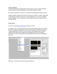
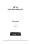
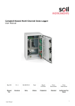
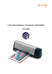
1
MMI UVCUT®
MMI
UVCut Software manual v2.0
Molecular Machines & Industries AG (MMI)
www.molecular-machines.com
01/05
1
MMI UVCUT®
MMI
MMI CELLTOOLS
MMI UVCUT
1
– User Manual:
SECURITY ADVICE
5
1.1
Laser safety
5
1.2
General safety
5
2
INSTALLATION OF THE SYSTEM
6
3
THE MMI CELLTOOLS INSTRUMENTATION FAMILY
6
4
PRINCIPLES OF MMI CELLCUT®
7
4.1
5
System set up
HANDLING OF SAMPLES
7
8
5.1
Single Step collection using the MMI Isolation Cap®
8
5.2
Preparation of the slides
9
6
MMI CELLTOOLS® – SOFTWARE DESCRIPTION
6.1
Overview of functions
10
10
6.2
Quick Start
6.2.1
System start-up
6.2.2
System preparation
6.2.3
Handling a new slide
6.2.4
System turn off
11
11
11
11
12
6.3
MMI CELLTOOLS® – Main Application
6.3.1
Main Window and plugins
6.3.2
User specific database
6.3.3
Video settings
6.3.4
Camera configuration
6.3.5
Fluorescence
6.3.6
XY stage motion
6.3.7
Slide overview for navigation
6.3.8
Additional Settings for the xy-stage
6.3.9
Calibration procedures
6.3.9.1 Camera orientation
6.3.9.2 Objective calibration
6.3.9.3 Lens OffSet calibration
6.3.10
Multi-User Report
13
13
13
15
15
16
17
17
19
19
19
20
22
23
01/05
2
MMI UVCUT®
6.3.11
6.3.12
MMI
Hardware self monitoring
Overview Image Quality
24
24
6.4
MMI CELLTOOLS® – UV CUT® Plug-in
6.4.1
Drawing the cutting contour
6.4.2
Using the MMI IsolationCap®
6.4.3
Cutting of objects
6.4.4
Group handling
6.4.5
Distance measurement
6.4.6
Pin positions
6.4.7
Autodocumentation
25
25
27
28
29
30
30
30
6.5
Calibration
6.5.1
Laser position
6.5.2
Correction of slide offset
31
31
32
7
33
DISPOSABLES
7.1
Slides
33
7.2
Caps
33
7.3
Cell Chamber
33
8
MAINTENANCE
34
9
TROUBLE SHOOTING
35
9.1
View
35
9.2
Movement
35
9.3
Drawing
35
9.4
Cutting
35
9.5
Collection
36
10
WARRANTY
37
11
CUSTOMER SUPPORT
38
12
SYSTEM DATA OVERVIEW
39
A SOFTWARE AND HOT KEY LIST
40
A.1 Shortcuts:
40
01/05
3
MMI UVCUT®
A.2 Hotkeys:
01/05
MMI
41
4
MMI UVCUT®
1
MMI
Security advice
The system should only be used for microdissection as described in the manual. Do
not use the system for any other purpose. Damage due to unauthorized use is not
subject to warranties. Persons who have been properly trained should only use the
system.
Read completely the Security Advice in Section 1 and the Manual before
operation.
1.1
Laser safety
This system contains a laser for microdissection. The system includes safety devices to prevent laser interference with the user. Due to the power losses incurred
as the beam passes through the microscope objectives the average power is nominal at the microscope work surface (i.e., at the membrane slide/tissue surface). If
the illumination arm is and tilted backwards, the lasing action is interrupted by an
electrical interlock. A blocking laser absorption filter is inside the microscope and
tilted backwards, the lasing action is interrupted and provides the necessary eye
protection for those times when the oculars may be used
To ensure full safety of the system please follow the steps below:
•
Turn off the laser with the key switch to prevent unauthorized operation of the
system.
•
Do not remove any objective while the laser is operating.
•
Never stare into the objective turret while the laser is operating.
•
Use only the provided objectives for the laser microdissection.
•
Never place reflecting objects in the beam path.
•
The laser source and the optical equipment are enclosed within the blue housing. To avoid electrical or laser hazards, do not open the housing. By design, the
laser beam is contained in a well-defined beam path, which is not serviceable,
by the user.
1.2
General safety
Do not disassemble the system. The installation of the system is provided by MMI
service personnel or MMI designated representative. Repairs, removal or exchange
of components beyond the operations described in this manual may only by carried
out by MMI service personnel or persons expressly authorized by MMI to do so. If
you have any problems with the instrument, contact MMI.
The power supply is installed by MMI. MMI assures that the system is provided with
the appropriate voltage. Do not change the power cords.
01/05
5
MMI UVCUT®
MMI
Avoid wet or dusty conditions near the system. If liquid gets inside the system, do
not attempt to use it. Contact MMI.
Unplug all electrical supply before cleaning the system. Do not use cleaning fluids or
sprays but only smooth and dry cloth.
If the stage control is not calibrated, table movements can be sudden and fast Assure that the work area around the table is free of clutter and material.
Read the manual of your microscope for specific microscope precautions. If you do
not have the manual contact your microscope provider or MMI.
2
Installation of the system
The system is installed by MMI Service personnel or our designated representative in the laboratory of the customer. After
the installation training will be provided in the use and operation of the system. The customer should not change the installation of the equipment (see precautions in Section 1).
3
Installation by
MMI
The MMI CELLTOOLS instrumentation family
The MMI Cell Tools are a fully modular instrumentation family,
including the following components:
-
MMI CELLCUT® laser microdissection to isolate single
cells or areas of tissue
-
MMI
-
MMI
-
MMI
-
Fluorescence microscopy extension for both fluorescence and quantum dot applications
CELLMANIPULATOR® optical tweezing to manipulate
cells or beads with an optical trap
CELLECTOR® automated micro-pipetting to mechanically manipulate cells or beads with a capillary
and mechanical micromanipulator
CELLEXPLORER pattern recognition software for PC
based image analysis
Any or all of these modules can be combined in one microscopic environment.
01/05
6
MMI UVCUT®
4
MMI
Principles of MMI CELLCUT®
The MMI CELLCUT® is a method to isolate, under microscopic
view, small areas or single cells from histological sections for
further microbiological analysis. Only the cell(s) wanted for
further investigation are cut out. DNA, RNA, as well as proteins
from undisturbed, pure samples can be investigated. No mechanical contact is necessary for the laser microdissection of
the samples. Thus the method avoids contamination of the
samples.
Isolation of cells
MMI
CELLCUT® permits comfortable working with high precision
and a large throughput without contamination.
Advantages of the
system
Several areas of interest can be microdissected in one automated operation and collected in the MMI ISOLATIONCAP®. One
MMI ISOLATIONCAP® used for Single Step Collection can collect
several dissections, even from different slides.
MMI ISOLATIONCAP
Review of the sample and selection of areas to cut do not have
to be directly followed by the cutting operation. The automated
cutting can be carried out later and by another person.
Scan and cutting –
time shifted operation possible
4.1
®
System set up
The MMI CELLCUT® system consists of a high performance
research microscope with motorized scanning stage, an electronically controlled, solid-state laser, requisite laser beam delivery and transfer optics and a high-end Pentium computer
with Windows and the sophisticated control software MMI
CELLTOOLS.
Components
All usual microscope features are available. The MMI
CELLTOOLS software controls the laser, image capture, and
scanning stage actions without blocking any other microscope
action.
01/05
7
MMI UVCUT®
MMI
In the figure,
change microscopic objective to
microscope objective
high precision xy stage
microscopic
objectiv
Focus control
Power control
UV Laser
High resolution
color CCD camera
PC with video display
5
Handling of samples
5.1
Single Step collection using the MMI Isolation Cap®
Microdissection for the isolation of cells is only useful when you
can remove the parts of the tissue you are interested in from
the tissue surroundings and from the slide. The single step
collection makes sampling of one or several isolated areas
easy and contamination free.
Separation of cells
from the slide
The Single Step Collection uses a protective membrane and a
reaction tube with a special adherent lid.
Single Step
Collection
The purpose of the protective membrane is:
Protective
membrane
to avoid contamination of the sample and
to facilitate easy removal and collection of the cut area
lid of tube
sample
membrane
tissue
slide
With the laser beam originating from below the stage, the laser
cuts through the tissue and the membrane. The separated tissue and membrane are collected with the lid of the reaction
tube.
The laser cuts around the cells to be isolated. For the collection
step, no additional radiation is used.
No radiation
directly on
dissectates
The membrane and the adhesive lid are chemically inert and
have no influence on further molecular biological processing.
01/05
8
MMI UVCUT®
MMI
The membrane material is a thin PET membrane. The membrane is transparent and does not perturb the light beam.
The lid of the reaction tube also contains a diffuser insert. The
lid improves the image quality remarkably and can be placed
directly on top of tissue and membrane during all operations.
5.2
Image quality
Preparation of the slides
The Single Step Collection of the dissection requires special
slides. The slides are provided with a 1.4µm thick, clear PET
membrane.
Intermediate slide
tissue
membrane
slide
Protective
membrane
The tissue is mounted on
the membrane as on an
ordinary slide.
Paraffin sections, cryo
sections or smears can
be used.
Dissection slide
membrane
tissue
slide
After the usual processing
(deparaffinize
staining,
etc) the membrane with
the tissue is inverted and
placed onto a new glass
slide and fixed in position
on the microscope stage.
Thus the tissue is now
under the membrane and
protected against contamination.
01/05
9
MMI UVCUT®
6
MMI
MMI CELLTOOLS® – Software description
6.1
Overview of functions
The MMI CELLTOOLS® together with the MMI UVCUT® plug-in
provides all necessary controls for:
•
displaying live video
•
saving images
•
motorized xy-stage
•
laser adjusting the power and laser focus
•
storing the preferred camera settings
•
manipulating the automatic cap lift
This results in an easy and user-friendly method for:
•
scanning the sample
•
documenting the sample
•
marking the path for the laser cutting around single cells or
cell clusters
•
marking several areas to be cut in one operation
•
storing the marked cutting paths (for later cutting)
•
dissecting the marked sample areas automatically
•
collecting the dissected areas without radiation radiation or
risking contamination of the isolated material(s)
The operation of all modules is controlled by the comfortable
and easy to use MMI CELLTOOLS®. The main application gives
all the tools necessary for displaying the video, saving the image, adjusting the camera control and basic xy-stage movement.
The MMI UVCUT® plug-in adds the specific MMI CELLCUT®
functions module.
MMI CELLTOOLS®
software with
UVCUT® plug-in
Additional plugins
Additional plugins for MMI CELLMANIPULATOR® and MMI
CELLEXPLORER® are available.
01/05
10
MMI UVCUT®
6.2
MMI
Quick Start
6.2.1
System start-up
To start MMI CELLCUT®, proceed the following steps as follows:
-
Start up the PC and allow the boot process to complete,
reaching the Windows desktop.
-
Turn on the microscope white light power supply.
-
Energize the electronic controller with the key. A yellow
LED will illuminate.
-
Start MMI CELLTOOLS® software and wait until the software has finished the load procedure.
-
Power the laser by pressing the button on the electronic
box controller. A green LED will illuminate.
6.2.2
System preparation
For the handling of the MMI UVCUT®, start with the definition of
a new setup.
For simplicity we call the first setup “Default”. In this setup the
laser power and focus settings, the on-screen laser position,
the xy-stage calibration and the camera settings for each objective will be stored. To reach the setup explorer, using the PC
mouse press “E” on the left side of the setup list.
Define new setup
If the objective you want to use does not appear in the objective list, define a new objective.
For each objective you prefer to use follow the calibration procedure for laser position, laser focus, laser power settings, xystage calibration (Chapter 6.3.9.2) and camera settings (Chapter 6.3.4).
6.2.3
Choose objective
Handling a new slide
Prepare your sample as described in Chapter 5 or following the
detailed application notes provided by MMI.
Prepare sample
membrane
tissue
slide
Define a new slide by using the menu item:
File->New Slide
or press
on the left side of the setup list.
Define new sample
slide
The slide editor will open and you can add a new slide by
pressing the " + " button. All documentation will be stored in a
01/05
11
MMI UVCUT®
MMI
folder with the same name, which you used for the slide.
Define the membrane slide work area by moving to the upper
left corner of the membrane window and pressing Limit1 and
then by moving to the bottom right corner for the membrane
window and pressing
Limit2.
Create overview
Use the objective with the lowest magnification (standard is
4x). By pressing the scan button the software creates an overview of sample(e.g., a "roadmap").
By double clicking into the overview you can navigate into the
area of interest. You can also use the cursor keys to move the
xy-stage or drag the blinking rectangle with the mouse
Navigate into the
area of interest
Move the Caplift down by pressing the corresponding button.
After lowering the Caplift you should adjust the microscope
stage fine focus, as needed.
Caplift down
Activate any button in the toolbar with a mouse click. For example the freehand drawing tool
and enables the user to
draw a line around the object to be microdissected.
Press the cut button to microdissect the marked object.
Lift the cap holder to collect the microdissected sample.
Cut
Caplift Up
Now everything is clear to take out the cap and proceed with
application.
6.2.4
System turn off
Shut down MMI CELLTOOLS® by using the Exit command, in the
File drop down menu.
File->Exit
Or press the cross on the right upper corner of the program
window. Shut down the laser controller by pressing the button
to deactivate the laser and then rotating the key to the off (vertical) position to deenergize the electronics controller.
Shutdown the PC as needed by using the keyboard command.
01/05
12
MMI UVCUT®
6.3
6.3.1
MMI
MMI CELLTOOLS® – Main Application
Main Window and plugins
Extended tool area:
Extended tool
area
The MMI CELLTOOLS® provides a live video screen of the actual
field of view of the microscope. To get a fast overview of the
sample, scan functions are available in the overview panel on
the right upper corner of the program window.
Live video and
overview scan
On the upper function bar the program gives access to the user
specific database. This database handles and stores all the
parameters defined by user.
User specific database
Each plug-in(or in other words module) appears as a separate
sheet on the right side of the program window. To switch from
one plug-in to the other user only has to click on the appropriate sheet.
Switching between
plugins
6.3.2
User specific database
All settings saved in the MMI CELLTOOLS® are unique for the
Microsoft Windows® user actually logged in. MMI CELLTOOLS®
fully supports the Microsoft Windows® user management.
During program start the last settings saved by the active user
are loaded.
Full support of
Microsoft Windows® user management
In the slide selection box you find all samples you defined in
the past. All documentation is saved under this name. To
01/05
13
MMI UVCUT®
MMI
change the database you press the
Editor:
button and get the slide
Define new slide, all parameters from the active slide
will be copied. You rename the slide by clicking on the
name.
Remove the active slide
Navigate through the slides
In the SetUp selection box you find all setups you defined for
the active slide. To change the database you press the “E”
button and get the SetUp Editor. To use this Editor see Slide
Editor described above. If you create a new slide all setups will
automatically be copied from the active slide.
If you run different experimental settings, e.g., microdissection
with bright field, microdissection with fluorescence of FITC or
tweezers it is recommended to define one setup for each of
these situations.
In the Objective selection box you find all objectives you defined for the active setup. To change the database you press
the “E” button and get the Objective Editor. To use this editor
follow the method of Slide Editor described above. If you create
a new setup all objectives will automatically been copied from
the active slide.
The distance between two points in the visible sample area
depends of the magnification of the active objective. Therefore
the program needs information on the chosen magnification for
the table control. From the menu, choose the appropriate objective for this magnification.
Choose and confirm magnification
If the xy-stage is still not following the mouse movement the
objective has to be recalibrated (See Objective calibration).
01/05
14
MMI UVCUT®
6.3.3
MMI
Video settings
In the standard setup the MMI CELLTOOLS® are using a specific
frame grabber board. Only with this frame grabber board is the
fluorescence mode fully supported. In this case the user has no
video setting available.
In special cases the MMI CELLTOOLS® also support Microsoft
Windows® vfw-video drivers. If the standard board is not installed, the user can select between different video drivers
supported by Windows®. Depending on the video driver selected specific video setting can be available.
6.3.4
Camera configuration
For different illumination setups, like bright field, phase contrast
or fluorescence, the ccd camera needs different parameters for
integration time and gain to produce good images. The camera
settings can be changed in the menu
Settings->Camera RC:
For the gain the automatic adjustment by the camera can be
selected. In this case the camera measures the light intensity
and attempts to choose appropriate settings. With the gain
limit you can define the maximum gain, which is used by the
camera in automatic mode. Note that a high gain induces a lot
01/05
Auto illumination
15
MMI UVCUT®
MMI
of more noise and the image quality may become poorer.
For standard (i.e., white) light choose an exposure time from
1/125 to 1/100000 according to light conditions, sample and
chosen objective. In the FL mode the camera corrects for the
fluctuation in the illumination (50 Hz Europe, 60 Hz North
America). The video screen shows you immediately the effects
of the camera setting. For fine tuning use the scrollbar Gain.
These settings are used until you change it again or switch to
another objective or setup.
Standard light
For fluorescence mode choose an exposure from 0.1 up to 8
according to light conditions, sample and chosen objective.
Typically, fluorochromes will differ in emitted intensity. For fine
tuning use the scrollbar Gain. This setting is used until you
change it again.
Fluorescence
As standard the camera control is set on Remote. In this mode
MMI CELLTOOLS can switch the exposure time between standard and fluorescence. Other camera setups are part of the
installation of the system. If you want to change to camera settings, which are not accessible through the camera menu of
mmi CellTools, choose Manual.
Camera control
The recommended (and installed) settings for the ccd camera
are listed in the annex of this manual.
If you change the illumination devices of your microscope you
should run the automatic White balance. If the button is
pressed the white balance is reset. If the button is released
color settings will be used.
White balance
To run the white balance you have to observe a white object
(white sheet of paper) with the microscope. If the observed
object is not white, the white balance will fail and the standard
settings will continue to be used.
6.3.5
Fluorescence
To define settings for a fluorescence experiment, it is recommended to start with defining a new setup (see chapter 6.3.2.)
For a set-up name use “Fluorescence dye1”, for example.
Now you can set the ccd camera on fluorescence exposure
time by clicking the Fluorescence button
. The fluorescence camera settings and video settings will automatically be
started.
To avoid photobleaching of the sample by the lamp intensity,
MMI CELLTOOLS® offers you a frozen image to draw the cutting
path. To freeze the image, click the right mouse button with the
cursor over the video screen. Choose Freeze from the context
menu. The video will be frozen, so that you can close the fluorescence illumination shutter. All procedures still work in the
01/05
Long term integration CCD camera
Frozen image
16
MMI UVCUT®
MMI
frozen image, but you will see no results. To check the results
you have to switch back to LTE (long term integration) mode by
using the context related menu (right mouse button). After going back one step you have to open the fluorescence illumination shutter and check the results.
6.3.6
XY stage motion
The movement of the stage is controlled by the MMI
CELLTOOLS®. Three different modes allow fast scanning for
overview or slow scanning for details.
or open the context menu by pressing the right
Choose
mouse button with the cursor in the video window and choose
Move with a left mouse click. By pressing the left mouse button
the table follows directly the mouse movement.
Three table movement modes
Direct mouse control
With the keyboard cursor keys the table can be moved slowly
and continuous in the four directions.
Keyboard control
The arrow keys in the number block on the PC keyboard move
the sample step by step with a 10% overlap from one viewing
area to the next. This allows searching for a particular location
in the sample without missing any part of the sample.
Keyboard control:
step by step
movement
6.3.7
Slide overview for navigation
In the right lower corner of the MMI CELLTOOLS® you will find a
panel representing the area of the sample defined by limit1
and
limit2 (See “Handling a new slide”). After selection of
button and scanning the slide
the area of interest with the
by pressing the start scan button
, this window shows you
an overview over your sample (the "roadmap image"). The
position of the detail of the large video image on the slide is
indicated with a red blinking point.
The maximum area of the scan is limited by the computer
memory and the magnification of the microscope. As standard,
a scan is executed with the 4x objective. In this case you can
define the left upper corner of the inner window of the membrane slide as limit1 and the right lower corner as limit2. To do
so, follow these steps:
-
move the xy-stage to the left upper corner of the membrane
-
and observe the small, blinkpress the limit1 button
ing, red rectangle in the overview.
-
move the xy-stage to the right lower corner of the membrane
-
press the limit2 button
01/05
Limit definition
Limit1
Limit2
and observe the small, blink17
MMI UVCUT®
MMI
ing, red rectangle in the overview.
For higher magnifying objectives the limits must be selected
closer together to get a good visible overview and not overload
the PC memory. If the scan area is too big the white/redblinking rectangle will be change to big red dot.
Define the actual area of the scan quickly with the
area tool.
After pressing the button you can select the area of interest in
the overview window using the PC mouse. Only the area of
interest will be scanned.
Area of interest
With a right click on the area of interest you can define the image quality of your scan. The highest possible quality is depending depends on the PC resources.
Begin the scan by pressing
the Start Scan button. With the
stop scan button you can always interrupt the scan. Also
pressing the ESC key will interrupt the scan.
With
you can open the overview image in the standard
Windows® image viewer. The time that Windows® needs to
open the application is dependent on the image size and PC
performance.
start scan
Stop scan
WINDOWS®
image viewer
copy button you can copy the overview image into
With the
the Windows® clipboard. Following this step the image is
available for all other standard Windows® applications.
copy to clipboard
save button you can save the overview image on
With the
your hard disk or other drive.
save image
on hard disk
A white/red-blinking rectangle represents the position of the
detail visible in the large video window. You can move this red
frame with the left mouse button. The motorized xy-table
moves automatically to the chosen detail. With this navigation
method you always see the position on the slide.
Navigation
You can also move to the position of interest by double clicking
into the overview area with the left mouse button.
01/05
18
MMI UVCUT®
6.3.8
Additional Settings for the xy-stage
MMI
Deceleration of
the xy-stage
If you press in the menu bar item
Settings->XYtable >XYmotionparam
it takes following window.
In this window you can limit the speed and acceleration of your
motorized xy-stage. This could be necessary if you mount a
heavy load on your xy-stage or if you’re working with liquid
cells otherwise no changes are recommended from the factory
settings..
Additionally you can define the time for a single laser shot (only
for MMI UVCUT®), by default is 50 msec. A range of 50 – 100
msec. is typical.
6.3.9
Single Laser pulse
duration
Calibration procedures
The MMI CELLTOOLS® are calibrated by MMI during the instrument installation. When you remove or add objectives or if
the original camera position has been changed you have to
repeat the calibration as described below.
6.3.9.1 Camera orientation
To check the camera orientation:
- Using the 40x objective move one small and remarkable point of the sample to the left upper corner of the
video panel.
-
Now press the right arrow key in the number pad.
If you move the object horizontally to the right upper corner and
the object is still on the same level, the camera orientation is
useable. If the result shows a shift between the two corners,
loosen the hex screws on the camera port and rotate the camera carefully. Repeat this "move and observe" operation again
until
01/05
19
MMI UVCUT®
MMI
the object moves on the same level across the monitor view.
When the object moves in a straight line the camera orientation
is correct. Retighten screws.
6.3.9.2 Objective calibration
When you add a new objective to your microscope you have to
calibrate the xy-stage control. Over the time of operation it may
be necessary to recalibrate the control, when contours and
cutting lines are no longer exactly fitting.
Take a slide with sample. Choose an objective in the objective
revolver and select the corresponding objective in the program.
If the objective does not exist create it as described in Section
6.3.2.
Calibration for
objectives
Confirm objective
Open in the menu bar item
UVCut->Calibration->Objective calibration
The objective calibration window appears.
To start the calibration of the active objective you can press the
button Calibrate.
The Calibration window will be minimized and you will find two
marked areas in the top left and bottom right of the screen
(calibration areas):
-
Move one small and remarkable point of the sample in
the upper left calibration area
-
Mark it with a left mouse button click
-
Move this point to the bottom right calibration area
01/05
Space key
20
MMI UVCUT®
-
Mark this point again with a left button click
-
Confirm calibration with a right mouse click.
MMI
Now the calibration window comes back. Accept the calibration
by pressing OK or discard your changes by pressing Cancel.
Remark: You always can switch between the move mode and
the mark mode by pressing the Space key on your keyboard.
In the move mode you see the hand courser in the mark
mode the marker cursor.
01/05
21
MMI UVCUT®
6.3.9.3 Lens OffSet calibration
MMI
Lens OffSet
calibration
When you install a new objective into your microscope you
have to calibrate Lens OffSet. Over the time of operation it may
be necessary to recalibrate the control, when contours and
cutting lines are no longer exactly fitting.
Calibration:
1. Take a slide with sample.
2. Make an objective calibration if necessary (See Objective
calibration).
3. Choose an objective in the objective revolver and select the
corresponding objective in the program. Make a shape around
some noticeable object. Move a noticeable object into center of
field of view.
4. Change an objective (physically and programmatically).
Please note, the Lens offset calibration procedure should go
from objective with smaller magnification to objective with
higher one for example from 4x to10x, and should have no
gap like 4x to 20x instead of 4x to10x or 10x to 20x etc.
Press the menu item
Settings->Lens OffSet calibration
Right mouse click to set up a difference between a shape and
corresponding object on the screen.
Repeat steps 1-4 for each objective.
01/05
22
MMI UVCUT®
6.3.10 Multi-User Report
MMI
Multi-User Report
User can get information about time spend for mmi Cell Tools
for each Windows user account.
Press the menu item
Settings->MultiUser Report
Or start it from
Start->Progreamms->mmiCellTools-> MultiUser Report
a time format is hhhh:mm:ss
01/05
23
MMI UVCUT®
6.3.11 Hardware self monitoring
MMI
Hardware
self monitoring
When system has a problem with some hardware, there is a
red blinker. The detailing of problem (or problems) see in that
combo box:
6.3.12 Overview Image Quality
Overview Image
Quality
For some special cases, for example, when you scanning a
huge image in overview window under 20x or more for full
slide, you can get a follow message:
for overcome these difficulties right mouse click under overview
window
and choose Overview Image Quality item. Because of smart
and fast algorithm, you will see nearly no visibly differences for
10 or yet more percents, but size will be match less.
by default Image Quality is 50%.
01/05
24
MMI UVCUT®
6.4
MMI
MMI CELLTOOLS® – UV CUT® Plug-in
The MMI UV CUT® plug-in appears as a separate sheet on the
right side of the program window.
The MMI UVCUT®
plug-in
To switch from one plug-in to the other you only have to click
on the appropriate sheet.
6.4.1
01/05
Drawing the cutting contour
25
MMI UVCUT®
MMI
The laser cuts along the contour you have drawn around the
interesting area you want to microdissect.
You can choose between freehand drawing and preset forms
such as circles, ellipses, lines and rectangles respectively.
Drawing modes
. The cursor
To activate the freehand drawing mode press
appears as a pencil. Press the left mouse button to draw the
contour around the area you are interested in. The program
closes the contour automatically if you have selected the option
“AutoEnclose Shape” in the menu UVCut->Draw and Cut.
Freehand drawing
Choose
or
. The cursor appears as a symbol of the
chosen form. Move the cursor (pressed left button) over the
length of the area you want to mark. If you right click on these
buttons you can choose to draw a circle or ellipse or respectively a rectangle or line. You can also give a defined dimension to your mark by typing the value in the corresponding input box.
Preset form
contours
The drawing mode can be activated through the buttons in the
MMI UV CUT® plug-in or in the context menu. The context
menu can be activating by pressing the right mouse button
(with the cursor in the video window) and choose Paint. The
last used drawing mode will be activated.
Switching to drawing mode
A quick switching between moving and drawing mode is possible by pressing the Space key on the keyboard.
You can delete the current contour by pressing the <del> key.
If you want to delete any object choose the delete mode with
Delete contours
button and click on the contour you want to delete.
With the context menu you also can delete one or all contours
of a group or all contours on your slide.
01/05
26
MMI UVCUT®
6.4.2
MMI
Using the MMI IsolationCap®
The MMI IsolationCap® for a Single Step Collection contains a
diffuser insert in the lid. Position the lid over the area of tissue
you want to review for maximum image quality during microdissection operations.
Image improvement using the
mmi IsolationCap®
To mount the tube simply slide the lid into the cap holder and
open the tube. The tube holder can easily be fixed to the automatic cap lift. The lift has a small magnet and two positioning
pins to hold the Inverted tube.
You can cut an object with the Caplift up or down. But the MMI
IsolationCap® works most reliably if microdissection is done
with the cap lowered onto the membrane surface.
The xy-stage can also be moved when the cap is down. The
maximum moveable distance, without lifting the cap, should be
limited to avoid tearing or other damage to the sample membrane. The Caplift free distance is 1000 microns (1mm) as the
default. Under specific conditions it could be helpful to increase
the free distance to be able to cut bigger objects with the cap
down.
Caplift Up/Down
button
Automatic cap
up/down function
The Caplift free distance can changed by using the menu item
UVCut->Caplift free distance
The Caplift free distance window appears:
If the cap is down on the tissue the cap will automatically be
lifted whenever you leave the free distance area by moving the
xy-stage. Then it will be repositioned repositioned automati01/05
27
MMI UVCUT®
MMI
cally.
If the Caplift is down you can cut only objects fitting into the
free distance area. If you work with a 0.5ml cap it is recommended to set a distance of about 1-2mm. The free distance
can be adjusted as needed when working with the 0.2ml or
1.5ml tubes.
6.4.3
Restriction for object size if cap lift
is down
Cutting of objects
The automated cutting along the contours makes your work
easy and fast. You can decide if you want to cut one area or
one group of areas.
For most applications the best cutting results are observed with
the 20x or the 40x objective. The user must select the appropriated objective in the objective selection box.
Automated
cutting
Magnification
The laser set up includes the stage’s parameters: speed, focus and power. It is essential for the cutting performance to
properly set these settings for each objective and tissue type.
The speed slider defines how fast the xy-stage moves during
the cutting procedure itself. It does not affect any other movement parameters of the xy-stage.
The focus slider adjusts the focus position of the laser beam in
z-direction within the tissue sample. The cutting performance is
very sensitive to this parameter. For example, the user would
expect to use different focus settings for soft tissue vs. bone.
The power slider defines the laser power. The power needed
at the sample normally will be proportional to sample thickness.
Choose the power setting, which enables clean laser cutting. In
laser microdissection, the laser is used as a "light scalpel".
The correct combination of focus and power define the sharpness of the scalpel tip, i.e.,. the overall cutting line width for a
given speed. These are the most important parameters for the
user to master.
Laser set up
Before dissecting the tissue of interest, test the laser performance in another area of the sample or on a sacrificial slide with
the same tissue. Draw a line or a circle and start cutting this
figure with a low speed. Change the focus and power parameters during cutting to observe the effects by the laser. The
sharpest line widths can be reached with power as low as possible and exact focus.
Test of cutting
To adjust the parameters start with high power value. The focus can be adjusted easier with high power. Make several cuts
with different focus values and compare the results. With a
reduced power the focus will be in a more defined area. Decrease the power step by step and repeat focusing until the
cutting line will be continuous, fine and clear.
Adjustment procedure
01/05
28
MMI UVCUT®
MMI
A cutting timer is selectable in the menu bar under
UVCut->Draw and Cut->Time left window
This timer gives you an estimate of the cutting time. To get
access to the sliders click on the timer with the left mouse button. The timer will disappear and comes back if you do not use
the sliders for more than three seconds.
You can store as many of the laser parameter settings that you
want for each objective. To define new setups see Chapter
6.3.2.
Laser microdissection can only be started with
.
Timer and access
to cutting parameters during cutting
Laser parameter
settings
Start cutting
„Repeat“ field does number of times of cutting.
Number of times
6.4.4
Group handling
If you have several types of cells to cut, you can define an
unlimited number of groups. If you draw an object it will always
be assigned to the actual group shown in the group selection
box.
The most common reason for using more than one group is to
permit the collection of different types of cells in different MMI
IsolationCaps® (i.e., Group A with Cap A, Group B with Cap B,
etc.).
Several dissectates in one
operation
All drawn areas belonging to one group are marked with the
same contour color.
You can adjust the drawing attributes, such as group name,
button
color and line thickness in the editor by pressing the
in the group name box. The group editor window appears:
01/05
Contour color and
thickness
29
MMI UVCUT®
6.4.5
Distance measurement
to measure different distances on the screen. The
Click
cursor appears as a ruler. Press the left mouse button and
drag the mouse. After releasing the mouse button you precisely see the measured distance.
6.4.6
MMI
Distance measurement tool
Pin positions
button you can save the current xy-stage position.
With the
With the
button you can delete it again. You can save as
many positions as you want.
create and delete
pin positions
You can move the xy-stage from one pin position to the next by
moving the pin position slider.
6.4.7
Autodocumentation
To set the auto documentation features, open the auto documentation window from the menu bar:
UVCut->Autodocumentation->Set Autodocumentation
01/05
Auto documentation for images
before and after
each cut
30
MMI UVCUT®
MMI
In the window you can activate the auto documentation and
define the parameters of the function. The program creates
automatically:
-
Text Report (.htm file)
-
First Image
-
Image for each shape of a group (if not marked only an
image before and after cutting a whole group will be
saved)
-
Last image
Note that you should work with a jpeg image in order to avoid
accumulation of many, large TIFF or BMP files on the PC hard
drive. The images in tiff format don’t appear in the report.
6.5
6.5.1
Calibration
Laser position
Precise cutting requires that the laser beam position be exactly
marked on the viewing screen. Over time and due largely to
mild vibration, to temperature extremes in the laboratory environment, or to accidental moving or jarring of the instrument,
recalibration of the laser position may be required.
Laser position
If the cutting action no longer follows the marked line you
should adjust the laser position. It should be done for each
magnification separately.
01/05
31
MMI UVCUT®
MMI
Cut a hole in the sample with
. A red arrow will illuminate
on the button when the laser fires or is on constantly.
Open UVCut from the menu bar and choose “Set Laser Position” in the menu “Calibration”. Fit the cursor cross with the
hole, which had been cut and confirm this position with a right
mouse button click. Continue with the next objective until the
beam position has been defined for each one.
6.5.2
Correction of slide offset
If you have removed the slide from the xy-stage that you have
drawn may not fit exactly when viewed on the monitor, if the
slide is returned to the xy-stage for further work. [0]For correction, you may reposition the contours by pressing and holding
the Alt key as you move the stage with the mouse. When the
contours once again fit properly to the image, release the Alt
key.
01/05
32
MMI UVCUT®
7
MMI
Disposables
7.1
Slides
Part No
Description
50101
RNase free, individually wrapped
50102
RNase free, individually wrapped, Box of 50 pieces
50103
Boxed, not individually wrapped, Box of 50 pieces
50104
Membrane, A4 sheet
50105
Glue Fixogum, 125 g
7.2
Caps
Part No
Description
50201
tube with adhesive lid, with diffusor, 500 µl (standard size)
50202
tube with adhesive lid, with diffusor, 500 µl (standard size) pack of 50
pieces
50203
tube with adhesive lid, without diffusor, 500 µl (standard size)
50204
tube with adhesive lid, without diffusor, 500 µl (standard size) pack of
50 pieces
50205
tube with adhesive lid, with diffusor 200 µl
50206
tube with adhesive lid, with diffusor 200 µl, pack of 50 pieces
50207
tube with adhesive lid, without diffusor 200 µl
50208
tube with adhesive lid, without diffusor 200 µl, pack of 50 pieces
50209
tube with adhesive lid, with diffusor 1.5 ml
50210
tube with adhesive lid, with diffusor 1.5 ml, pack of 50 pieces
50211
tube with adhesive lid, without diffusor 1.5 ml
50212
tube with adhesive lid, without diffusor 1.5 ml, pack of 50 pieces
7.3
Cell Chamber
Part No
Description
50301
cell chamber with membrane complete with Petri dish coated with silicone pack of 10 pieces
01/05
33
MMI UVCUT®
8
MMI
Maintenance
Maintenance and service should be only performed by qualified
MMI personnel or our designated representative(s).
The MMI CELLCUT® contains no user-serviceable parts.
01/05
Maintenance and
service
34
MMI UVCUT®
9
MMI
Trouble shooting
This Section provides help for problems that can occur when
working with UV CUT. Most of the problems can be easily
solved. When needed, please refer to the problem description
and the trouble shooting tips.
9.1
View
Image not clear, too dark, too bright or no image on monitor
•
Check the camera set up and compare it with the camera
manual.
•
Check that there is sufficient illumination from the white
light, and that the light is not obstructed.
•
For improved image quality, use the diffuser.
•
The microscope port button should be set on “side”.
9.2
Movement
The movement is not accurate and repeatable; the stored positions cannot be found again.
•
Movement
Check if the sample is fixed correctly on the stage and
cannot move.
9.3
Drawing
The drawing line is difficult to see.
•
View
Drawing
Choose dark line colors for bright samples and bright line
colors for dark samples. Increase the thickness of the line if
needed.
9.4
Cutting
No cutting can be observed.
•
The laser has not been switched on (key and button).
•
The magnification chosen not correspond to the objective
in use.
•
The laser power is too low.
•
The laser focus is not well adjusted.
•
The cutting is not perfect; bridges remain in the cutting
path. Repeat the cut if necessary.
•
The cutting speed is too high.
•
The cutting path does not correspond to the drawn contour.
Check the camera orientation (6.3.9.1). The laser position
01/05
Cutting
35
MMI UVCUT®
MMI
may need to be adjusted. Incorrect magnification may be
selected.
•
The calibration may have changed. Recalibrate when necessary.
9.5
Collection
The dissected objects are not collected.
•
Make sure that the lid is placed directly over the treated
area and lowered down onto the membrane. Ensure that it
is not on the metal frame.
•
Assure that the cutting action has been complete and successful. Adjust laser settings or repetitions to achieve full
penetration of the beam through the membrane and tissue.
01/05
Collection
36
MMI UVCUT®
MMI
10 Warranty
In Europe and Asia:
The optical system and the control system are protected
against defects in materials and workmanship for a period of
one year from the date of installation. This warranty is limited to
repair or replacement of system components which returned to
MMI within the given one (1) year period. Unauthorized repairs,
replacements and modification will cancel all warranties.
The microscope is not included in the warranty given by MMI
AG. The microscope warranty depends on the manufacturer of
the microscope, the country of location, and the responsible
distributor. Consult Service at MMI AG for details.
software
optical system
microscope
In North America:
For the standard CellCut instrument configuration, the optical
system, including the microscope, and the control system are
protected against defects in materials and workmanship for a
period of one year from the date of installation. Any failure
resulting from unauthorized system modification, abuse, neglect, misuse, or acts of nature are not covered under this or
any warranty.
Custom instrument configurations may be covered under the
terms of the standard warranty via written acknowledgement by
MMI Inc.
Unauthorized instrument repairs, replacements, or modifications cancel all warranties expressed or implied.
Consult Service at MMI Inc. for details.
01/05
37
MMI UVCUT®
MMI
11 Customer support
For questions about the MMI CELLCUT®
contact
(technical, consumables, warranties) please contact:
Europe and Asia:
[email protected]
Molecular Machines & Industries AG (MMI),
Flughofstrasse 37, CH - 8152 Glattbrugg,
Switzerland
+41 - (0)1 - 8 09 10 10
+41 - (0)1 - 8 09 10 11
North America:
MMI Molecular Machines & Industries Inc.
North America
Don Armstrong, Ph.D.
P.O. Box 23991
Knoxville, TN 37933-1991
USA
+1 - (865) 988 7500
+1 - (865) 988-6666
MMI via the Internet:
www.molecular-machines.com
01/05
38
MMI UVCUT®
MMI
12 System data overview
Required minimum workspace:
The table for the microscope, laser, optical equipment, computer monitor and keyboard requires a minimum dimension of
1,20m x 0,90m
The computer should be positioned under or near the table.
The camera/computer connection cable is 2m long to ensure
reliable data transfer.
Components:
Name
Description
Specifications
microscope
research microscope,
Zeiss; Nikon (standard configuration); Olympus; Leica
(inverted) with fluorescence port
xy scanning table scanning table with stepper
motors
scanning area : (120x100)mm²
accuracy : < 1µm
laser system
wavelength : 355nm;
line voltage : 200-240 VAC
or 100-110 VAC,
50-60 Hz, 1,0A
Optical and elec- Laser control unit
tronical coupling MMI
unit
ccd camera with
power supply
DXC-390P
3CCD Color Video Camera;
CCD-Chip : 1/3-inch 3-Chip with
Power HAD technology
horizontal resolution : 800 TV lines;
Sensitivity : 2000 lux at F8;
single to noise ratio : 61dB
computer
Pentium PC with Win XP Pro
With RGB frame grabber
control software
MMICELLTOOLS with
MMIUVCUT® plug-in
32 bit Software
01/05
39
MMI UVCUT®
MMI
A Software and hot key List
A.1 Shortcuts:
MMI CELLTOOLS®
application run
MMI CELLTOOLS®
Main Window
Ctrl+Alt+F12
Main Menu
File
Alt+F
New Slide
Ctrl+N
Save Image
Ctrl+S
Start Record Movie
Ctrl+Alt+S
Stop Record Movie
Ctrl+Alt+D
Exit
Alt+F4
Edit
Alt+E
Copy Image (for Move mode)
Ctrl+C
Copy Shape (for Paint mode)
Ctrl+C
Insert Shape (for Paint mode)
Ctrl+V
Video
Alt+V
Driver
(non Flashpoint card)
Ctrl+D
Video Type (non Flashpoint card)
Ctrl+T
Help
Help Topics
F1
Info
Alt+I
MMI UVCUT®
01/05
Alt+H
only
Cap lift up/down
F2
Select next marker
Ctrl +Tab
Select prev marker
Shift+Tab
40
MMI UVCUT®
MMI
A.2 Hotkeys:
For any window
Accept changes & close window
ENTER key
Close current opened window
ESC key
Stop current procedure or cancel last command ESC key
Main Window
Changing type of cursor
SPACEBAR key
Screen to first marker go
HOME key
Screen to last marker go
END key
Screen to next marker go
+ key
Screen to prev marker go
- key
Screen to next marker go
PAGE UP key
Screen to prev marker go
PAGE DOWN key
Screen 20% go up
UP ARROW key
Screen 20% go down
DOWN ARROW key
Screen 20% go left
LEFT ARROW key
Screen 20% go right
RIGHT ARROW key
Screen 20% go up
MOUSE WHEEL UP
Screen 20% go down
MOUSE WHEEL DOWN
Screen 90% go left
NUMPUD 6 key
Screen 90% go right
NUMPUD 4 key
Screen 90% go up
NUMPUD 8 key
Screen 90% go down
NUMPUD 2 key
Emergency stop motion
NUMPUD 5 key
Shift the contours relative to the sample
(Press ALT while moving the sample)
01/05
ALT+ Move mode
41