1
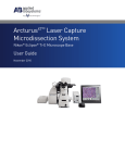
ArcturusXT™ Laser Capture
Microdissection System
AutoScanXT Software Module
User Manual
For Research Use Only. Not intended for any animal or human therapeutic or diagnostic use.
Information in this document is subject to change without notice.
APPLIED BIOSYSTEMS DISCLAIMS ALL WARRANTIES WITH RESPECT TO THIS DOCUMENT, EXPRESSED OR IMPLIED, INCLUDING BUT NOT LIMITED TO
THOSE OF MERCHANTABILITY OR FITNESS FOR A PARTICULAR PURPOSE. TO THE FULLEST EXTENT ALLOWED BY LAW, IN NO EVENT SHALL APPLIED
BIOSYSTEMS BE LIABLE, WHETHER IN CONTRACT, TORT, WARRANTY, OR UNDER ANY STATUTE OR ON ANY OTHER BASIS FOR SPECIAL, INCIDENTAL,
INDIRECT, PUNITIVE, MULTIPLE OR CONSEQUENTIAL DAMAGES IN CONNECTION WITH OR ARISING FROM THIS DOCUMENT, INCLUDING BUT NOT
LIMITED TO THE USE THEREOF, WHETHER OR NOT FORESEEABLE AND WHETHER OR NOT APPLIED BIOSYSTEMS IS ADVISED OF THE POSSIBILITY OF
SUCH DAMAGES.
TRADEMARKS
The trademarks mentioned herein are the property of Life Technologies Corporation or their respective owners.
© 2010 Life Technologies Corporation. All rights reserved.
4458765 Rev. A
07/2010
Contents
1.
Introduction to AutoScanXT Software Module ...................................................................4
2.
Installation of the AutoScanXT Module ..............................................................................4
3.
Using AutoScanXT.............................................................................................................5
4.
Creating a New Analysis File .............................................................................................5
4.1
Step 1: Pixel Selections…………….…………………………………………………………..6
4.2
Step 2: Analysis Settings ................................................................................................8
4.3
Step 3: Learn – Analysis of the Static Image ..................................................................8
5.
Performing Microdissection................................................................................................9
5.1
Selecting Items for Microdissection ................................................................................9
5.2
Microdissecting Selected Items ....................................................................................10
6.
Using a Previously Saved Analysis File ...........................................................................11
7.
Working with a Previously Saved Image……………………………………………………...10
8.
Scanning a Tiled Image or Whole Cap Area………………………………………………....11
9.
Texture Analysis…………………………………………………………………………….......17
9.1
Step 1: Texture Selections............................................................................................17
9.2
Step 2: Analysis Settings ..............................................................................................18
9.3
Step 3: Learn – Analysis of the Static Image ................................................................18
10. Morphology Analysis.........................................................................................................18
10.1
Step 1: Morphology Selections .....................................................................................19
10.2
Step 2: Analysis Settings ..............................................................................................19
10.3
Step 3: Learn – Analysis of the Static Image ................................................................20
11.
Advanced AutoScanXT – Using a 2nd Stained Slide ........................................................20
12.
Combining AutoScanXT Analysis Files............................................................................21
ArcturusXT™ Laser Capture Microdissection System AutoScanXT User Manual
3
1.
Introduction to AutoScanXT Software Module
The ArcturusXT™ Laser Capture Microdissection (LCM) AutoScanXT software module is
an image analysis program that automatically identifies areas for microdissection based
on user-defined criteria. This program performs optimally with high contrast samples and
is simple and straightforward to use. With the software controls, the user first selects
typical regions of interest (ROI’s) and background areas, and then AutoScanXT employs
these parameters to automatically identify areas in the sample for the microdissection
process. The information used to identify the areas for microdissection is stored in an
AutoScanXT analysis file and can be used subsequently on other areas from the same
sample or on other similarly stained tissue samples. AutoScanXT also allows the
combination of multiple analysis files, enabling the complex analysis of samples with
differences in staining intensities, tissue thickness and variations in light intensities.
2.
Installation of the AutoScanXT Module
Important: The AutoScanXT software module
requires ArcturusXT Operating Software of version
2.0 or higher. The AutoScanXT icon will be present
on all operating software versions 1.2 and higher,
but will be unavailable for activation. You must have
v2.0 or higher to activate this option. Further, the
AutoScanXT feature will remain unusable until the
option has been purchased and activated with a
viable license key.
To download the most recent version of operating
software, visit the Life Technologies/Applied
Biosystems website at:
http://www.appliedbiosystems.com.
Figure 1. Select Panel.
1. Once the software module has been purchased,
make a copy of “SoftwareKeys.xml” file, found in the following location: C:/Program
Files/Molecular Devices/ArcturusXT.
Note: If this file is not present, please make sure that you have operating software
v2.0, or higher, installed.
2. Send the copied file to the appropriate Life Technologies representative, as indicated
in the purchase confirmation letter.
3. An updated “SoftwareKeys.xml” file will be returned containing the information to
activate the AutoScanXT feature.
ArcturusXT™ Laser Capture Microdissection System AutoScanXT User Manual
4
4. When the activation key has been received, close the ArcturusXT Operating Software
if currently opened.
5. Copy the updated “SoftwareKeys.xml” file received and paste into the following
location: C:/Program Files/Molecular Devices/ArcturusXT.
6. Click yes to the prompt “This file already exists, Do you want to replace it?”
7. Open the ArcturusXT Operating Software.
8. The AutoScanXT button located in the Select Tool Pane will now be active (Figure 1).
3.
Using AutoScanXT
The AutoScanXT application provides three levels of analysis; Pixel, Texture and
Morphology. You can apply as many levels as is necessary to achieve the most
desirable results for a given specimen, but at a minimum the Pixel Analysis must be
performed. For most samples, Pixel Analysis will be sufficient.
Pixel Analysis: Differentiates regions based on pixel color. This is best suited for
samples with high contrast or definite color differences between regions of interest and
background.
Texture Analysis: Differentiates based on textures within the tissue sample. An
example of textural differences is fibrous versus cellular areas of a tissue sample.
Morphology Analysis: Filters regions defined by Pixel and Texture Analysis, by
differentiating based on the shape and size of ROIs from the designated background
areas. An example of morphology differences is epithelial versus inflammatory cells.
Note: The AutoScanXT software module operates only on JPEG images. The software
will automatically switch to JPEG if you select the acquire image option and filter out
other image types if you are opening an existing image file.
4.
Creating a New Analysis File
Analysis files are used to scan images and
designate regions of interest for
microdissection. Analysis files are “learned”
based on user-defined criteria and each is
created on a static image. Once created, an
Analysis File may be used on subsequent
samples. To use saved Analysis Files, see
Section 6. Analysis files may be created
using a newly acquired static image or a saved
Figure 2. Acquire New Image.
image file. This section refers to the use of newly
acquired images. To use saved image files, see Section 7.
1. Initialize ArcturusXT operating software.
ArcturusXT™ Laser Capture Microdissection System AutoScanXT User Manual
5
2. Load prepared sample(s) and CapSure® LCM Caps onto the ArcturusXT LCM
System.
3. Go to the desired location on the slide and adjust magnification and image settings
as desired.
4. Click on the “AutoScanXT” icon found in the Select Tool Pane.
5. In the AutoScanXT window, select “Acquire Image” and then click OK (Figure 2).
6. A static image will appear along with the “Scan” tab of the AutoScanXT Settings
window (Figure 3).
7. Select <Create New> from the pull down menu located beneath “Step 1: Select
Analysis file”.
8. An updated Settings window will appear containing the Pixel Analysis tab.
9. Type in a name for the new analysis file (Figure 4).
10. Proceed to Pixel selections in Step 4.1.
Figure 3. AutoScanXT Settings Window,
Scan Tab.
Figure 4. Pixel Analysis Tab.
4.1 Step 1: Pixel Selections
1. Identify Regions of Interest (ROI):
a. Click on the “ROI (Region of Interest)” selection (Figure 4).
b. Click the static image to select representative pixels of the color variations
that you wish to include for consideration during the analysis of the image.
c. For each point selected, a drawing of two circles will be placed on the static
image (Figure 5). Only the inner shaded circle area is utilized during
analysis (see “Area of Influence” below for further information).
2. Identify Background:
a. Click on the Background selection (Figure 4).
ArcturusXT™ Laser Capture Microdissection System AutoScanXT User Manual
6
b. Click on the image to select representative pixels of the color variations that
you wish to exclude from consideration during the analysis of the image.
c. The background area will be depicted by a shaded circle within a box
(Figure 5). Only the shaded area is utilized during analysis (see “Area of
Influence” below for further information).
3. To remove a selected ROI or Background point, place the cursor within the
shaded circle, right click and select “Remove Point”.
Note: It is recommended to start by utilizing only a minimal number of ROIs and
background points (3-4 of each if possible). A large number of points for either
one of these parameters will result in increased processing time of the image and
do not necessarily improve the scan results.
Figure 5. ROI and Background Selection.
4. To remove either a ROI or Background selection, click on “Clear” (Figure 4).
This command removes all selected points in the static image for either ROI or
background (dependent upon selection), allowing you to start the selection
process over.
5. Assign additional parameters for the Pixel analysis files.
a. “Min ROI Area (um2)”: This value defines the minimum area of an object
that will be considered for analysis and included in the regions list for
microdissection. For most applications, the default value shown (equivalent
to 100 pixels on the image) is the most suitable.
b. “Area of Influence”: This value defines the number of pixels surrounding
either the ROI or background point that you select to be included as part of
7
XT
Arcturus ™ Laser Capture Microdissection System AutoScanXT User Manual
the analysis process. This area will be averaged and used by the algorithm
to differentiate the ROI from background. The default value of 3 is suitable
for most samples.
4.2 Step 2: Analysis Settings
1. Select the Algorithm (Figure 4).
a. Pixel Learn: A basic algorithm used with high contrast color samples
b. Pixel Learn Advanced: Used with samples containing more complex
colors or intensity variations and where the “Pixel Learn” algorithm does not
provide adequate results
c. Pixel Detect (gray scale): Used for samples containing black and white
differences.
2. Select the Classification (Figure 4).
a. Uni-Modal: Used with samples in which there is a sharp contrast between
background and ROI.
b. Multi-Modal: Used with samples containing a number of background color
variations.
i.
Mode activates upon selection of Multi-Modal.
ii. Color Patterns: The first classification setting indicates the number
of color patterns, both for ROI and background.
iii.
Prob. Threshold: The next setting indicates the level of accuracy.
Note: Decreasing the probability threshold will favor ROI detection
and increase false positive, while an increase will result in less false
positives at the risk of missing some ROIs.
3.
Assign the Stringency (Figure 4). A low stringency value will favor ROI
detection but may also include more background as part of the identified items,
while high values will decrease inclusion of false positive areas, but at the risk
of missing some ROIs.
4.3 Step 3: Learn – Analysis of the Static Image
1. Define microdissection properties for the items to be identified by AutoScanXT
during analysis.
a. By default, glass slides will dictate LCM only items and Membrane slides
will dictate UV cut and IR capture items.
b. If UV Cut is unchecked within the AutoScanXT window, it will override the
default slide-specific settings described above.
Note: Items will not be marked as UV cut objects if “LCM only” has been
checked in the Select Panel, on the top level operating software regardless of
slide type.
ArcturusXT™ Laser Capture Microdissection System AutoScanXT User Manual
8
2. Click “Learn” to save the analysis parameters and to initiate the analysis of the
static image (Figure 4).
3. Upon completion, the Regions tab will appear containing a list of ROI items and
the static image will be updated with identified ROI areas marked (Figure 6).
Figure 6. Regions Tab and ROI List.
4. The ROI list provides the following information for each item:
a. Location: Coordinates of the ROI location as it relates in the live image.
b. Probability: How well the ROI matches the analysis criteria.
c. Size: Area in um2.
5. If the ROI areas are not satisfactory, you may return to the Pixel Analysis at any
time by clicking on the tab.
a. Additions or deletions to the ROI and/or background points, as well as
changes to other analysis criteria, can be made within this tab.
b. The updated information will be incorporated into the analysis file upon
clicking the “Learn” button to re-scan and update the static image.
c. Alterations of the Pixel Analysis can be repeated as many times as needed
until desirable results are achieved.
6. If desirable results are achieved with Pixel analysis, proceed to Section 5,
“Performing Microdissection”.
7. If desired results have not been achieved, you may add texture and/or
morphology analysis layers by clicking on the appropriate tab (Figures 10 and
11), further refining the definition of the ROI areas for microdissection. See
Sections 8 and 9 for further information.
ArcturusXT™ Laser Capture Microdissection System AutoScanXT User Manual
9
5.
Performing Microdissection
5.1 Selecting Items for Microdissection
1. Once the Analysis file is complete, the Regions tab and the associated analyzed
static image will have items identified as candidates for microdissection.
Figure 7. Selecting Items for Microdissection.
2. To select items for microdissection, you may either click on a ROI object in the
static image or check the box next to the item in the regions list (Figure 7).
a. The selected item will change color on the static image, corresponding to
the active capture group.
b. Use the “Select All” button to select all items on list.
3. To remove a selected item from the microdissection list, click either on the item
in the static image or from the list.
a. The color outlining the item will revert back to green and the check mark will
be removed from the associated item on the Regions List.
4. To make changes to any of the selected items, you must transfer the items to the
live image.
a. Click the “Copy Items” button (Figure 7).
b. The transferred items will appear on the live image and will be listed under
the Drawing Items in the Select Tool Pane.
ArcturusXT™ Laser Capture Microdissection System AutoScanXT User Manual
10
c. All features on the ArcturusXT operating software are now available to you
for manipulating the selected items. Refer to the ArcturusXT Laser Capture
Microdissection User Manual for details.
5.2 Microdissecting Selected Items
You may microdissect the selected ROIs either directly from the AutoScanXT
Regions tab, or by transferring the items to the live image and utilizing the main
features of the ArcturusXT operating software.
Note: Default microdissection for UV cut items follows the same order used in live
video microdissection – LCM (IR capture) first, followed by UV laser cutting or vice
versa. To switch this order, go to the Microdissection Options dialog in the main
ArcturusXT operating software.
1. Microdissect from the Regions Tab
a. Click the “Harvest Button” located on the Regions List tab (Figure 7).
b. The ArcturusXT LCM System will automatically place a cap onto the slide
and begin the microdissection process for any items selected in Step 5.1.
Important: Before initiating this process, ensure that the Live Image
matches the position of the static image used to identify the ROIs. If
the location does not match, the cap may not be placed accurately over the
items for microdissection and microdissection process will not proceed.
2. Microdissect from the live image
a. Transfer the selected items from the Regions list to the live image.
i.
Click the “Copy Item” button.
ii. The transferred items will appear on the live image and will be listed
under the Drawing Items in the Select Tool Pane.
iii.
All features on the ArcturusXT operating software are now available to
you for manipulating the selected items.
iv. Proceed with microdissection following the standard methods. Refer
to the ArcturusXT LCM user manual for details.
6.
Using a Previously Saved Analysis File
Analysis files are created on a static image. This may be done by using a newly acquired
static image or a previously saved image file. This section refers to the use of newly
acquired images. To use saved image files, see Section 7.
1. Initialize ArcturusXT operating software.
2. Load prepared sample(s) and CapSure® LCM Caps onto the ArcturusXT
operating software.
3. Go to the desired location on the slide and adjust magnification and image
settings as desired.
ArcturusXT™ Laser Capture Microdissection System AutoScanXT User Manual
11
4.
5.
6.
7.
Click on the “AutoScanXT” icon found in the Select Tool Pane.
In the AutoScanXT window, select “Acquire Image” and then click OK.
A static image will appear along with the AutoScanXT Settings window.
Select the desired saved Analysis file from the pull down menu located beneath
“Select Analysis File” (Figure 8).
8. Define the microdissection
properties for items that will be
identified by selecting either UV
cut or LCM only.
a. By default, glass slides will
dictate LCM only items and
Membrane slides will dictate
UV cut and IR capture items.
b. If UV Cut is unchecked within
the AutoScanXT window, it
will override the default slidespecific settings described
above.
Note: Items will not be marked as
UV cut objects if “LCM only” has
been checked in the Select Panel,
on the top level operating software
regardless of slide type.
Figure 8. Open Saved Analysis File.
9. Assign additional parameters for the
Pixel analysis.
a. “Max ROIs”: This value indicates the maximum number of ROIs to be
created during the scan.
b. “Max ROI area”: This value represents the largest size area for an object
to be included as a selected item. A value of “0” reflects no maximum area.
c. “Retrieve Holes”: If checked, any areas defined as “holes” within an
identified object will now be included as a ROI item.
10. Click “Scan” to start the analysis.
11. Upon completion of the analysis the static image will be marked up and Regions
tab will be updated with the list of ROI items.
12. Proceed to Microdissection (See Section 5).
7.
Working with a Previously Saved
Image
Location (coordinates) of a saved image in
relation to the slide is retained with the image
itself when the image is created by the
ArcturusXT software. AutoScanXT uses this
Figure 9. Open Saved Image File.
information during the process of transferring
selected ROI items. If it is desired to use a different slide than the one from which the
ArcturusXT™ Laser Capture Microdissection System AutoScanXT User Manual
12
analysis file was created, it may be required to move these microdissection objects
(ROIs), as location of a section may not match up exactly.
1. Click on the “AutoScanXT” icon.
2. In the AutoScanXT window, select “Open Saved Image” and then click OK
(Figure 9).
3. Select and open the desired image.
Reminder: The AutoScanXT software module operates only on JPEG images.
The software will automatically switch to JPEG if you select the acquire image
option and filter out other image types if you are opening an existing image file.
4. The AutoScanXT Settings window will appear along with the saved image.
5. From the Settings window you may create a new analysis file or select a
previously saved analysis file. See above for further details on the use of the
analysis files.
Note: It is recommended to transfer selected ROIs to the live image to ensure
accuracy of the microdissection (see Section 5.2.2).
8.
Scanning a Tiled Image or Whole Cap Area
Analysis files may be applied to scan tiled images or the entire area under a CapSure®
LCM cap. To scan a large tiled image or the area under a CapSure LCM Cap, you must
use a previously saved Analysis File. To create a new Analysis File, see Section 4,
“Creating a New Analysis File”.
Special Notes:
i. If performing analysis of a Whole Cap
area, place a CapSure LCM cap prior
to initiating AutoScanXT.
ii. If you need to move to a new area of
the slide while in AutoScanXT, check
the “Move Stage” box located in the
“Slide Overview Tab” and then click
Figure 10. Open Saved Image File.
on any area within the AutoScanXT
overview image. The stage will then move
to that location.
iii. If the overview image has been updated within the main software window, the
AutoScanXT overview image should be updated as well. To update the
overview, click on “Update Slide Overview” and the image will be replaced.
1. Click on the “AutoScanXT” icon.
2. In the AutoScanXT window, select “Acquire Tiled Image” and then click OK
(Figure 10). The “Tiled AutoScanXT Settings” window will appear, with a copy of
the overview image in the center (Figure 11).
ArcturusXT™ Laser Capture Microdissection System AutoScanXT User Manual
13
3. Click on either the “Select
Area” or “Whole Cap” radio
button in the lower right
corner of the Slide Over tab
(Figure 11).
a. Tiled Image: Using the
mouse or stylus, draw
a box within the
overview image to
designate the scan
area (Figure 11). A
green box will appear
in the overview image.
Figure 11. Tiled Image AutoScanXT.
b. Whole Cap: When
“Whole Cap" is selected
(Figure 12), a green box
appears inside the green
circle which depicts the
CapSure Cap. The area
within this square will be
analyzed.
Figure 12. Whole Cap AutoScanXT.
ArcturusXT™ Laser Capture Microdissection System AutoScanXT User Manual
14
4. Click on the “Scan” tab and select the desired Analysis File from the menu
(Figure 13).
5. Assign additional parameters
for the Pixel analysis.
a. “Max ROIs”: This
value indicates the
maximum number of
ROIs to be created
during the scan.
b. “Max ROI area”:
This value represents
the largest size area
for an object to be
included as a
selected item. A
value of “0” reflects
no maximum area.
c. “Retrieve Holes”: If
checked, any areas defined as
Figure 13. Select Analysis File.
“holes” within an identified
object will now be included as a ROI item.
6. Click “Scan” to start the
analysis.
7. The “Tiled Image and
Regions” tab will appear as
AutoScanXT software begins
analysis of the region (Figure
14). On the left side of the
window will appear the grid of
the tiles being scanned, and
below that is listed the
approximate time remaining
for analysis. As the analysis
of each tile is complete, the
image of the tile will appear
in the grid and the regions list
will be populated for that tile.
The tile being will be
outlined in red.
Figure 14. Analysis in Progress
Note: To abort the analysis process at any point, click on the “Abort” button,
located in the lower left corner of the “Tiled Image & Regions” tab. When
pressed, AutoScanXT will complete analysis of the tile in progress, and the
remaining tiles will be left unanalyzed.
ArcturusXT™ Laser Capture Microdissection System AutoScanXT User Manual
15
8. Upon completion of the analysis, the grid will be fully populated with images for
each of the individual analyzed tiles, and the Regions list will be updated with the
list of ROIs for each tile.
Viewed, ROIs
Selected
Viewed, Nothing
Selected
Active tile
Has not been
viewed
Figure 15. Tiles Images and Regions
9. Click on any tile to review the ROIs for microdissection. The tiles will be colorcoded based on the review status (Figure 15).
Blue = Tile has not been viewed
Red = Active tile
Light Green = Tile has been viewed, but no ROIs have been
selected
Dark Green = Tile has been viewed and at least one ROI has been
selected
10. Proceed to Selecting Items and Performing Microdissection (See Section 5).
ArcturusXT™ Laser Capture Microdissection System AutoScanXT User Manual
16
9.
Texture Analysis
Texture Analysis is a second level criterion that may be added onto the Pixel Analysis
criteria. If needed, this can further refine the analysis of the static image and improve the
results of the selection of ROIs for microdissection. Texture analysis uses polygons to
define the ROI and background areas. The Texture Analysis tab (Figure 16) will appear
once Pixel Analysis has been run.
9.1 Step 1: Texture Selections
1. Select ROI and Background.
a. Click on the image to create a
starting point for the
polygons.
b. Click on the image to define
the end of each line and
double click to close the
polygon and define the
region.
2. To remove either a ROI or
Background polygon, right-click
within the polygon and select
“Remove Polygon”.
3. Define microdissection properties
Figure 16. Texture Analysis Tab.
for items that will be identified by
selecting either UV cut or LCM
only.
a. By default, glass slides will dictate LCM only items and Membrane slides
will dictate UV cut and IR capture items.
b. If UV Cut is unchecked within the AutoScanXT window, it will override the
default slide-specific settings described above.
Note: Items will not be marked as UV cut objects if “LCM only” has been
checked in the Select Panel, on the top level operating software regardless of
slide type.
4. Assign additional parameters for Texture Analysis.
a. Min ROI Area um2: This value defines the minimum size for an area to be
considered for analysis and included in the regions list as a candidate for
microdissection.
b. Sub-Image Size: This value defines the pixel area that will be used to
segment each selected area to determine all textural differences within the
selected area. For example a value of 8, the algorithm will segment each
selected area into an area of 8 by 8 pixels to use in the analysis.
ArcturusXT™ Laser Capture Microdissection System AutoScanXT User Manual
17
9.2 Step 2: Analysis Settings
1. Select the Classification
a. Uni-Modal: Used with samples in which there is a sharp difference in
texture between background and ROI.
b. Multi-Modal: Used with samples containing a number of background color
variations.
i. Mode activates upon selection of Multi-Modal.
ii. Color Patterns: The first classification setting indicates the number
of color patterns, both for ROI and background.
iii. Prob. Threshold: The next setting indicates the level of accuracy.
Note: Decreasing the probability threshold will favor ROI detection
and increase false positive, while an increase will result in less false
positives at the risk of missing some ROIs.
2. Assign the Stringency. A low stringency value will favor ROI detection but may
also include more background as part of the identified items, while high values
will decrease inclusion of false positive areas, but at the risk of missing some
ROIs.
9.3 Step 3: Learn – Analysis of the Static Image
1. Click “Learn” to save the analysis parameters and to initiate the Texture analysis.
2. Upon completion, the Regions tab will appear containing a list of ROI items and
the static image will be updated with identified ROI areas marked.
3. If the ROI areas are not satisfactory, you may repeat Texture Analysis, but you
must first repeat Pixel Analysis before returning to Texture Analysis.
a. Additions or deletions to the ROI and/or background areas, as well as
changes to other analysis criteria, can then be made within this tab.
b. The updated information will be incorporated into the analysis file upon
clicking the “Learn” button to re-scan the static image.
c. Alterations of the Texture Analysis may be repeated as many times as
needed until desirable results are achieved.
4. If desirable results are achieved with Texture analysis, proceed to Section 5,
“Performing Microdissection”.
5. If the results remain insufficient and more specificity is required, you may add
Morphology Analysis by clicking on the appropriate tab. See Section 9 for further
information.
10. Morphology Analysis
Morphology is a third level of analysis and serves as a filter for regions previously
identified using Pixel analysis or combined Pixel and Texture analyses. Morphology
analysis performs best when Pixel and Texture analyses have been optimally executed,
having provided clearly defined items on the Regions list. Texture Analysis is not required
ArcturusXT™ Laser Capture Microdissection System AutoScanXT User Manual
18
for Morphology Analysis and may be excluded from the process. The Morphology
Analysis tab (Figure 17) will appear once Pixel Analysis has been run.
10.1 Step 1: Morphology
Selections
Morphology selections are made
using items found on the Regions
List. ROI and Background selections
are made by clicking on the
highlighted item on the static image.
1. Select ROI. On the static image,
select at least two representative
ROI areas.
2. Select Background. On the static
image select at least two
background objects.
Note: You may exclude the
selection of either ROI or
Figure 17. Morphology Analysis Tab.
Background during Morphology
Selections, but NOT both. You must identify at least one criterion.
3. Define microdissection properties for items that will be identified by selecting
either UV cut or LCM only.
a. By default, glass slides will dictate LCM only items and Membrane slides
will dictate UV cut and IR capture items.
b. If UV Cut is unchecked within the AutoScanXT window, it will override the
default slide-specific settings described above.
10.2 Step 2: Analysis Settings
1. Select the Classification:
a. Uni-Modal: Use with samples where there is a sharp difference in
morphology between background and ROI.
b. Multi-Modal: Used with samples containing a number of background color
variations.
i. Mode activates upon selection of Multi-Modal.
ii. Color Patterns: The first classification setting indicates the number
of color patterns, both for ROI and background.
iii. Prob. Threshold: The next setting indicates the level of accuracy.
Note: Decreasing the probability threshold will favor ROI detection
and increase false positive, while an increase will result in less false
positives at the risk of missing some ROIs.
19
ArcturusXT™ Laser Capture Microdissection System AutoScanXT User Manual
2. Assign the Stringency. A low stringency value will favor ROI detection but may
also include more background as part of the identified items, while high values
will decrease inclusion of false positive areas, but at the risk of missing some
ROIs.
10.3 Step 3: Learn – Analysis of the Static Image
1. Click “Learn” to save the analysis parameters and to initiate the Morphology
analysis.
2. Upon completion, the Regions tab will appear containing a list of ROI items and
the static image will be updated with identified ROI areas marked.
3. If the ROI areas are not satisfactory, you may repeat Morphology Analysis, but you
must first repeat Pixel Analysis before returning to the Morphology tab.
a. Once Pixel Analysis has been redone, reselect ROI and/or Background
points within the Morphology Analysis tab. The reselection within
Morphology Analysis is required as this analysis is based on results of the
previous Pixel and Texture analysis steps.
b. Changes to other analysis criteria can then be made within this tab.
c. The updated information will be incorporated into the analysis file upon
clicking the “Learn” button to re-scan the static image.
d. Alterations to the Morphology Analysis may be repeated as described
above until desirable results are achieved.
4. If desirable results are achieved with Morphology analysis, proceed to Section 5,
“Performing Microdissection”.
5. If the results remain insufficient and more specificity is required, you may continue
to repeat Morphology Analysis by clicking on the appropriate tab, or return to Pixel
or Texture Analysis tabs to refine the analysis. See respective sections above for
further information on those analyses.
11. Advanced AutoScanXT – Using a 2nd Stained Slide
It may be desirable to use the results of the AutoScanXT analysis on additional slides
containing serial sections of the same tissue and same stain, after the analysis and
microdissection has been completed on the first (reference slide).
Additionally, it may be desirable to perform analysis on a reference slide which is stained
using a procedure that is not compatible with downstream analysis of the microdissected
samples. The ROIs identified using the stained section can be transferred to the live
image of the unstained slide for microdissection, avoiding the compromising stain of the
reference slide in the microdissected material.
Note: The live image should be the slide from which you wish to microdissect.
1. On the first slide follow the instructions above and complete the AutoScanXT
analysis up to “Learn” and until satisfactory results are achieved.
ArcturusXT™ Laser Capture Microdissection System AutoScanXT User Manual
20
2. If desired, select items for microdissection.
3. To microdissect, use the “Harvest” button within the AutoScanXT window, or
transfer the selected items to the live image by using the Copy Items button and
use the microdissect buttons on the top level to capture.
4. Leave open both the AutoScanXT static image and the AutoScanXT Settings
window with the Regions Tab present.
5. Remove the first slide (reference slide) from the stage and replace it with the
second slide.
6. On the top level operating software, delete all items from the Drawing Items list in
the Select Panel.
7. Locate the same area on the second slide live image as used for the original
AutoScanXT analysis file.
8. Use the Copy Items button to transfer the selected items in the Regions List to the
live image.
9. If necessary, use the “Select” tool in the main ArcturusXT operating software to
move the transferred items to the appropriate location on the active slide.
10. Use the microdissection commands on the top level to microdissect.
Important: Before initiating this process, ensure that the Live Image matches
the position of the static image used to identify the ROIs. If the location does
not match, the cap may not be placed accurately over the items for
microdissection and microdissection process will not proceed.
11. Repeat steps 3-6 as needed for additional serial sections.
12.
Combining AutoScanXT Analysis Files
It may be desirable to combine various saved
analysis files, incorporating the analysis parameters
for differences in staining intensities, tissue
thickness and variations in light intensities. The
resulting new analysis file incorporates all of the
information from each of the files used to create
them.
Note: You can only combine files that use the same
algorithms. You cannot edit a combined analysis
file.
1. Create and save as many new individual
analysis files as needed or use previously
Figure 18. Combining Analysis Files.
saved analysis files.
2. When you are ready to combine the files, click on the AutoScanXT button found in
the Select Panel.
3. Select either Acquire or Save image.
4. In the “AutoScanXT Settings” window, click “Combine” (Figure 18).
ArcturusXT™ Laser Capture Microdissection System AutoScanXT User Manual
21
5. In the “Combine AutoScanXT Analysis File” window, click Browse to locate the
analysis files you wish to combine (Figure 19).
6. In the “Select Analysis Files to Combine” window, hold down the CTRL key and
select the files that you wish to combine (Figure 20). When finished click OPEN.
7. The “Combine AutoScanXT Setting” window will be updated with a list of files that
will be combined. Enter a name for this file in the area titled “New Analysis
Filename”.
8. Click Combine
9. The newly created file may now be found in the pull down menu for use on a static
image.
Figure 19. Combine Files and Create a
New Analysis File.
Figure 20. Browse Analysis Files to
Combine into New Analysis File.
ArcturusXT™ Laser Capture Microdissection System AutoScanXT User Manual
22
Part Number 4458765 Rev. A 07/2010
Headquarters
5791 Van Allen Way | Carlsbad, CA 92008 USA
Phone 760.603.7200
www.lifetechnologies.com
Technical Resources and Support
For the latest technical resources and support information
for all locations, please refer to our Web site at
www.appliedbiosystems.com/support